
YASKAWA AC Drive V/J1000
External Heatsink Attachment
Option Manual
MANUAL NO. EZZ020568
To properly use the product, read this manual thoroughly and retain
for easy reference, inspection, and maintenance. Ensure the end user
receives this manual.
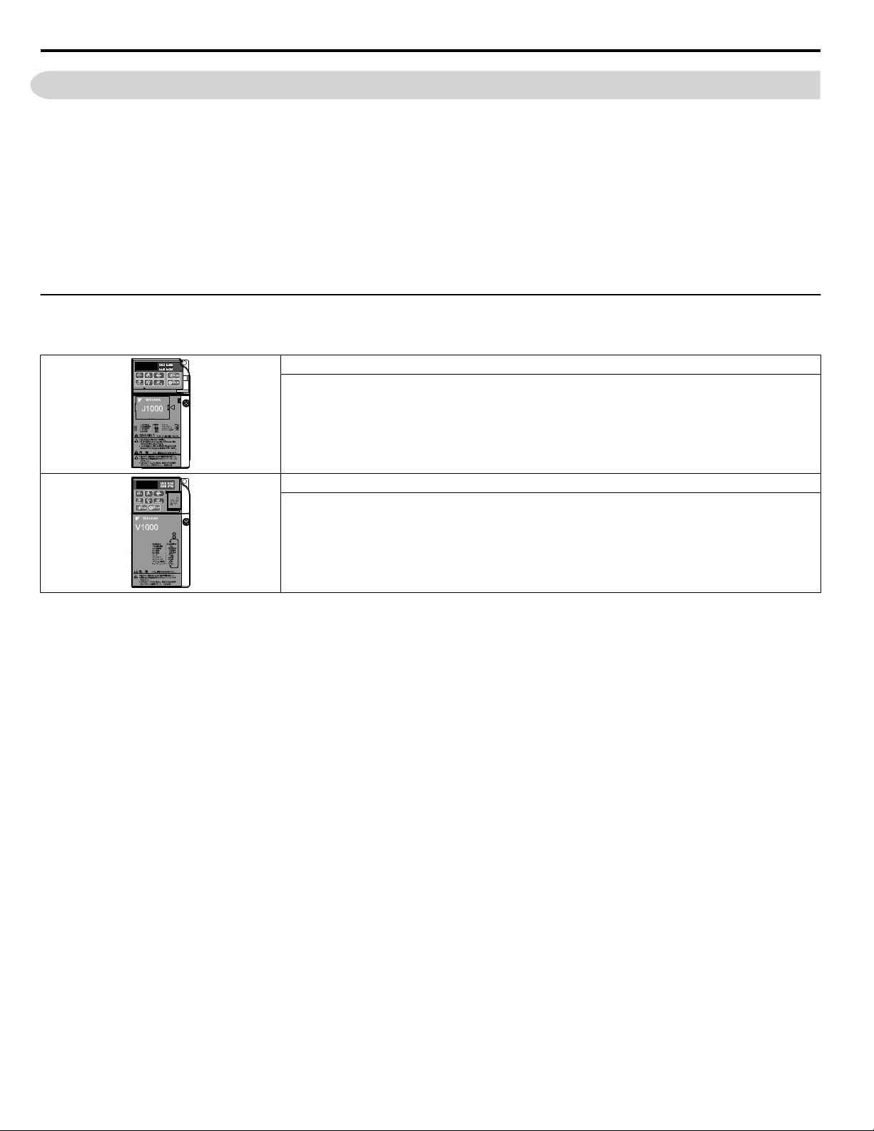
Type: CIMR-J
Type: CIMR-V

This Page Intentionally Blank
2
YASKAWA V1000/J1000 AC Drive External Heatsink Kit Option Manual EZZ020568
Copyright © 2013 YASKAWA AMERICA, INC. All rights reserved.
All rights reserved. No part of this publication may be reproduced, stored in a retrieval system, or transmitted, in any form or
by any means, mechanical, electronic, photocopying, recording, or otherwise, without the prior written permission of Yaskawa.
No patent liability is assumed with respect to the use of the information contained herein. Moreover, because Yaskawa is
constantly striving to improve its high-quality products, the information contained in this manual is subject to change without
notice. Every precaution has been taken in the preparation of this manual. Yaskawa assumes no responsibility for errors or
omissions. Neither is any liability assumed for damages resulting from the use of the information contained in this publication.

Table of Contents
1 PREFACE AND SAFETY.........................................................................................4
2 GENERAL SAFETY.................................................................................................5
3 ABOUT THIS OPTION.............................................................................................7
4 EXTERNAL HEATSINK OPTION INSTALLATION PROCEDURE.........................9
5 INSTALLATION PROCEDURE BY DRIVE MODEL..............................................12
6 EXTERNAL HEATSINK OPTION PART NUMBERS BY DRIVE MODEL.............21
7 REVISION HISTORY..............................................................................................23
YASKAWA V1000/J1000 AC Drive External Heatsink Kit Option Manual EZZ020568
3
1 Preface and Safety
Yaskawa manufactures products used as components in a wide variety of industrial systems and equipment. The selection and
application of Yaskawa products remain the responsibility of the equipment manufacturer or end user. Yaskawa accepts no
responsibility for the way its products are incorporated into the final system design. Under no circumstances should any
Yaskawa product be incorporated into any product or design as the exclusive or sole safety control. Without exception, all
controls should be designed to detect faults dynamically and fail safely under all circumstances. All systems or equipment
designed to incorporate a product manufactured by Yaskawa must be supplied to the end user with appropriate warnings and
instructions as to the safe use and operation of that part. Any warnings provided by Yaskawa must be promptly provided to
the end user. Yaskawa offers an express warranty only as to the quality of its products in conforming to standards and
specifications published in the Yaskawa manual. NO OTHER WARRANTY, EXPRESS OR IMPLIED, IS OFFERED.
Yaskawa assumes no liability for any personal injury, property damage, losses, or claims arising from misapplication of its
products.
u
Applicable Documentation
The following manuals are available for the J1000 and V1000 Drives:
J1000 Series AC Drive Quick Start Guide
Read this manual first. This guide contains basic information required to install and wire the drive. This
guide provides basic programming and simple setup and adjustment. Refer to the J1000 Technical Manual
for complete descriptions of drive features and functions.
V1000 Series AC Drive Quick Start Guide
Read this manual first. This guide contains basic information required to install and wire the drive. This
guide provides basic programming and simple setup and adjustment. Refer to the V1000 Technical Manual
for complete descriptions of drive features and functions.
1 Preface and Safety
4
YASKAWA V1000/J1000 AC Drive External Heatsink Kit Option Manual EZZ020568
2 General Safety
u
Supplemental Safety Information
Read and understand this manual before installing, operating, or servicing this option. The option must be installed according
to this manual and local codes.
The following conventions are used to indicate safety messages in this manual. Failure to heed these messages could result in
serious or possibly even fatal injury or damage to the products or to related equipment and systems.
General Precautions
• The diagrams in this manual may be indicated without covers or safety shields to show details. Replace the covers or shields before
operating the drive and run the drive according to the instructions described in this manual.
• Any illustrations, photographs, or examples used in this manual are provided as examples only and may not apply to all products to
which this manual is applicable.
• The products and specifications described in this manual or the content and presentation of the manual may be changed without notice
to improve the product and/or the manual.
• When ordering a new copy of the manual due to damage or loss, contact your Yaskawa representative or the nearest Yaskawa sales
office and provide the manual number shown on the front cover.
• Order a replacement from your Yaskawa representative or the nearest Yaskawa sales office if nameplate becomes worn or damaged.
WARNING
Read and understand this manual before installing, operating or servicing this drive. The drive must be installed according
to this manual and local codes.
The following conventions are used to indicate safety messages in this manual. Failure to heed these messages could result
in serious or fatal injury or damage to the products or to related equipment and systems.
DANGER
Indicates a hazardous situation, which, if not avoided, will result in death or serious injury.
WARNING
Indicates a hazardous situation, which, if not avoided, could result in death or serious injury.
WARNING! may also be indicated by a bold key word embedded in the text followed by an italicized safety message.
CAUTION
Indicates a hazardous situation, which, if not avoided, could result in minor or moderate injury.
CAUTION! may also be indicated by a bold key word embedded in the text followed by an italicized safety message.
NOTICE
Indicates a property damage message.
NOTICE: may also be indicated by a bold key word embedded in the text followed by an italicized safety message.
2 General Safety
YASKAWA V1000/J1000 AC Drive External Heatsink Kit Option Manual EZZ020568
5
u
Safety Messages
DANGER
Electrical Shock Hazard
Do not connect or disconnect wiring while the power is on.
Failure to comply will result in death or serious injury.
Before installing the option, disconnect all power to the drive. The internal capacitor remains charged even after the power
supply is turned off. The charge indicator LED will extinguish when the DC bus voltage is below 50 Vdc. To prevent electric
shock, wait at least five minutes after all indicators are off and measure the DC bus voltage level to confirm safe level.
WARNING
Electrical Shock Hazard
Do not operate equipment with covers removed.
Failure to comply could result in death or serious injury.
The diagrams in this section may show drives without covers or safety shields to show details. Be sure to reinstall covers or
shields before operating the drives and run the drives according to the instructions described in this manual.
Do not remove covers or touch circuit boards while the power is on.
Failure to comply could result in death or serious injury.
Do not allow unqualified personnel to use equipment.
Failure to comply could result in death or serious injury.
Installation, maintenance, inspection, and servicing must be performed only by authorized personnel familiar with
installation, adjustment, and maintenance of this product.
Do not touch any terminals before the capacitors have fully discharged.
Failure to comply could result in death or serious injury.
Before installing the option, disconnect all power to the drive. The internal capacitor remains charged even after the power
supply is turned off. The charge indicator LED will extinguish when the DC bus voltage is below 50 Vdc. To prevent electric
shock, wait at least five minutes after all indicators are off and measure the DC bus voltage level to confirm safe level.
Do not use damaged wires, stress the wiring, or damage the wire insulation.
Failure to comply could result in death or serious injury.
Fire Hazard
Tighten all terminal screws to the specified tightening torque.
Loose electrical connections could result in death or serious injury by fire due to overheating of electrical connections.
NOTICE
Observe proper electrostatic discharge procedures (ESD) when handling the drive and circuit boards.
Failure to comply may result in ESD damage to the drive circuitry.
Do not use unshielded cable for control wiring.
Failure to comply may cause electrical interference resulting in poor system performance. Use shielded, twisted-pair wires
and ground the shield to the designated shield ground location.
Check all the wiring to ensure that all connections are correct after installing the option and connecting any other
devices.
Failure to comply could result in damage to the option.
2 General Safety
6
YASKAWA V1000/J1000 AC Drive External Heatsink Kit Option Manual EZZ020568

3 About this Option
The installation of the External Heatsink Mounting Kit to V1000 or J1000 AC drives allows the drive heatsink, a major heat
generating component of the drive, to protrude to the exterior of a customer supplied enclosure. Large amounts of heat that
would normally be trapped inside the enclosure, are dissipated outside the enclosure, thus facilitating a more compact and less
costly enclosure selection. Mounting attachments to secure the drive within a panel cutout are supplied. A convective back
plate, mounted to the backside of the heatsink, is supplied with certain kits to improve natural convection air flow over the
heatsink.
This option may be used when the installation environment conforms to the specifications in Table 1.
u
Installation Environment
Install the drive in an environment matching these specifications to help prolong the optimum performance life of the drive.
Table 1 Installation Environment
Environment Conditions
Installation Area Indoors
Ambient Temperature
IP20/NEMA Type 1 enclosure: -10 °C to +40 °C (14 °F to 104 °F)
IP20/IP00 Open-Chassis enclosure: -10 °C to +50 °C (14 °F to 122 °F)
Finless Type: IP20/IP00 enclosure: -10 °C to +50 °C (14 °F to 122 °F)
NEMA Type 4X/IP66 enclosure: -10 °C to +40 °C (14 °F to 104 °F)
Drive reliability improves in environments without wide temperature fluctuations.
When using an enclosure panel, install a cooling fan or air conditioner in the area to ensure that the air temperature inside
the enclosure does not exceed the specified levels.
Do not allow ice to develop on the drive.
Humidity 95% RH or less and free of condensation
Storage Temperature -20 °C to +60 °C (-4 °F to +104 °F)
Surrounding Area
Install the drive in an area free from:
• oil mist and dust
• metal shavings, oil, water or other foreign materials
• radioactive materials
• combustible materials (e.g., wood)
• harmful gases and liquids
• excessive vibration
• chlorides
• direct sunlight
Altitude
Vibration
10 to 20 Hz at 9.8 m/s
2
20 to 55 Hz at 5.9 m/s
2
Orientation Install the drive vertically to maintain maximum cooling effects.
Table 2 Installation Environment
Environment Conditions
Installation Area Indoors
Ambient Temperature
IP20/NEMA Type 1 enclosure: -10 °C to +40 °C (14 °F to 104 °F)
IP20/IP00 Open-Chassis enclosure: -10 °C to +50 °C (14 °F to 122 °F)
Finless Type: IP20/IP00 enclosure: -10 °C to +50 °C (14 °F to 122 °F)
NEMA Type 4X/IP66 enclosure: -10 °C to +40 °C (14 °F to 104 °F)
Drive reliability improves in environments without wide temperature fluctuations.
When using an enclosure panel, install a cooling fan or air conditioner in the area to ensure that the air temperature inside
the enclosure does not exceed the specified levels.
Do not allow ice to develop on the drive.
Humidity 95% RH or less and free of condensation
Storage Temperature -20 °C to +60 °C (-4 °F to +104 °F)
3 About this Option
YASKAWA V1000/J1000 AC Drive External Heatsink Kit Option Manual EZZ020568
7

Environment Conditions
Surrounding Area
Install the drive in an area free from:
• oil mist and dust
• metal shavings, oil, water or other foreign materials
• radioactive materials
• combustible materials (e.g., wood)
• harmful gases and liquids
• excessive vibration
• chlorides
• direct sunlight
Altitude
Vibration
10 to 20 Hz at 9.8 m/s
2
20 to 55 Hz at 5.9 m/s
2
Orientation Install the drive vertically to maintain maximum cooling effects.
NOTICE: Prevent foreign matter such as metal shavings and wire clippings from falling into the drive during installation. Failure to comply
could result in damage to the drive. Place a temporary cover over the top of the drive during installation. Remove the temporary cover before
drive start-up, as the cover will reduce ventilation and cause the drive to overheat.
3 About this Option
8
YASKAWA V1000/J1000 AC Drive External Heatsink Kit Option Manual EZZ020568
4 External Heatsink Option Installation Procedure
u
Drive Dimensions with External Heatsink Option Installed
This section provides figures and tables of drive dimensions with the External Heatsink Option installed.
Table 3 Drive Models and Dimensions
Series Drive Model Number Reference
J1000
CIMR-JoBo0001 to 0010
Figure 1
CIMR-Jo2o0001 to 0020
CIMR-Jo4o0001 to 0011
V1000
CIMR-VoBo0001 to 0018
CIMR-Vo2o0001 to 0020
CIMR-Vo4o0001 to 0011
CIMR-Vo2o0030 to 0069
Figure 2
CIMR-Vo4o0018 to 0038
4 External Heatsink Option Installation Procedure
YASKAWA V1000/J1000 AC Drive External Heatsink Kit Option Manual EZZ020568
9
Attachment B
N-M4 Mounting Holes
Attachment A
W1
W
H1
H
D1
D2
min. D3
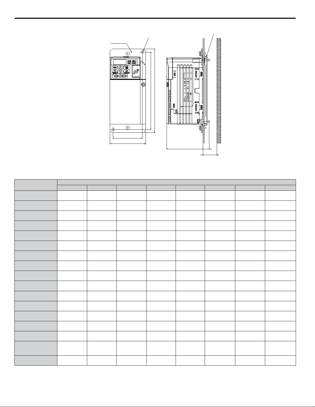
Figure 1 External Heatsink Option Outline Dimensions
Table 4 External Heatsink Option Outline Dimensions by Model (Figure 1)
Drive Model
CIMR-V or J
Dimensions mm (in)
W W1 H H1 D1 D2 D3 N
oBo0001
oBo0002
68
(2.7)
56
(2.2)
160
(6.3)
148
(5.8)
69.5
(2.7)
12
(0.5)
30
(1.2)
2
(0.1)
oBo0003
68
(2.7)
56
(2.2)
160
(6.3)
148
(5.8)
69.5
(2.7)
42
(1.7)
50
(2.0)
2
(0.1)
oBo0006
108
(4.3)
96
(3.8)
158
(6.2)
144
(5.7)
79.5
(3.1)
58
(2.3)
70
(2.8)
4
(0.2)
oBo0010
108
(4.3)
96
(3.8)
158
(6.2)
144
(5.7)
96
(3.8)
58
(2.3)
70
(2.8)
4
(0.2)
oBo0012
140
(5.5)
128
(5.0)
158
(6.2)
144
(5.7)
98
(3.9)
65
(2.5)
70
(2.8)
4
(0.2)
oBo0018
170
(6.7)
158
(6.2)
158
(6.2)
144
(5.7)
115
(4.5)
65
(2.5)
70
(2.8)
4
(0.2)
o2o0001
o2o0002
68
(2.7)
56
(2.2)
160
(6.3)
148
(5.8)
69.5
(2.7)
12
(0.5)
30
(1.2)
2
(0.1)
o2o0004
68
(2.7)
56
(2.2)
160
(6.3)
148
(5.8)
69.5
(2.7)
42
(1.7)
50
(2.0)
2
(0.1)
o2o0006
68
(2.7)
56
(2.2)
160
(6.3)
148
(5.8)
69.5
(2.7)
62
(2.4)
70
(2.8)
2
(0.1)
o2o0008
o2o0010
108
(4.3)
96
(3.8)
158
(6.2)
144
(5.7)
71
(2.8)
58
(2.3)
70
(2.8)
4
(0.2)
o2o0012
108
(4.3)
96
(3.8)
158
(6.2)
144
(5.7)
79.5
(3.1)
58
(2.3)
70
(2.8)
4
(0.2)
o2o0018
o2o0020
140
(5.5)
128
(5.0)
158
(6.2)
144
(5.7)
78
(3.0)
65
(2.5)
70
(2.8)
4
(0.2)
o4o0001
108
(4.5)
96
(3.8)
158
(6.2)
144
(5.7)
71
(2.8)
13.5
(0.5)
30
(1.2)
4
(0.2)
o4o0002
108
(4.5)
96
(3.8)
158
(6.2)
144
(5.7)
71
(2.8)
28
(1.1)
40
(1.6)
4
(0.2)
o4o0004
108
(4.5)
96
(3.8)
158
(6.2)
144
(5.7)
79.5
(3.1)
58
(2.3)
70
(2.8)
4
(0.2)
o4o0005
o4o0007
o4o0009
108
(4.5)
96
(3.8)
158
(6.2)
144
(5.7)
96
(3.8)
58
(2.3)
70
(2.8)
4
(0.2)
o4o0011
140
(5.5)
128
(5.0)
158
(6.2)
144
(5.7)
78
(3.0)
65
(2.5)
70
(2.8)
4
(0.2)
4 External Heatsink Option Installation Procedure
10
YASKAWA V1000/J1000 AC Drive External Heatsink Kit Option Manual EZZ020568
Mounting Hole (x4-Ma)
Attachment 1
Attachment 3
Attachment 2
W
W1
D1
D2
min. D3
H
H1
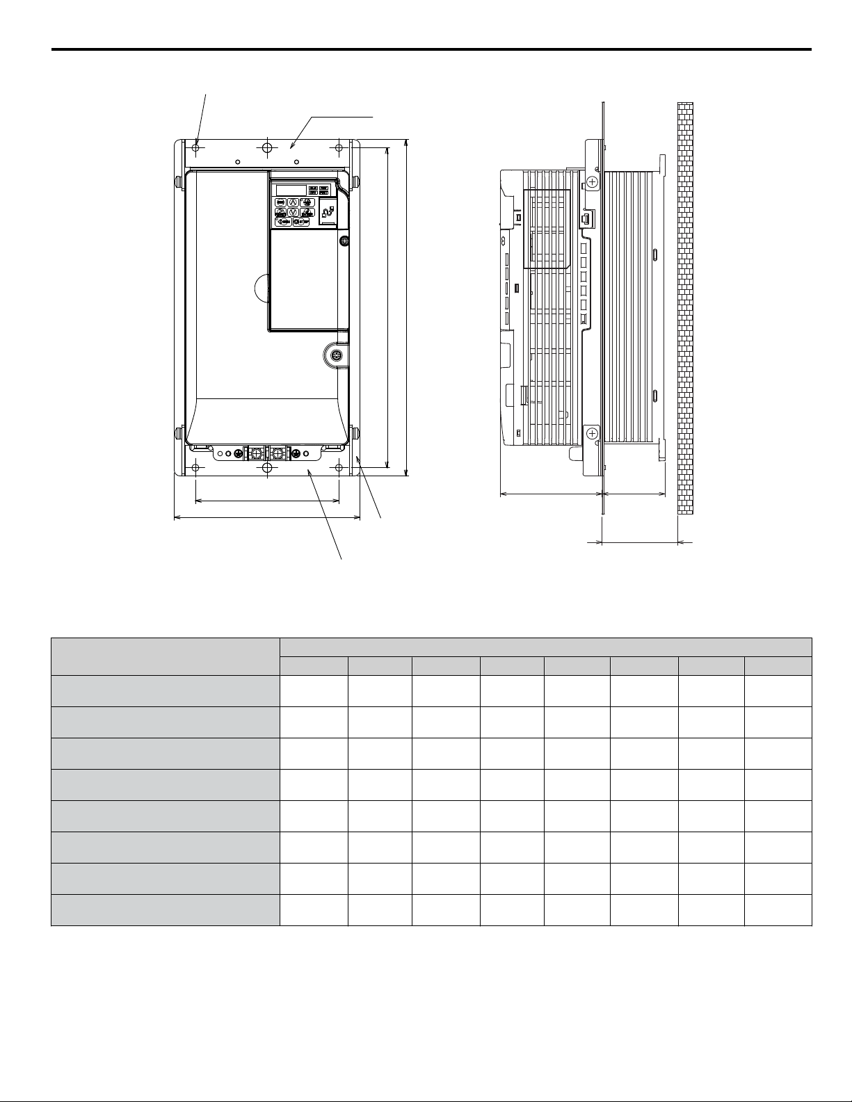
Figure 2 External Heatsink Option Outline Dimensions
Table 5 External Heatsink Option Outline Dimensions by Model (Figure 2)
Drive Model
CIMR-V
Dimensions mm (in)
W W1 H H1 D1 D2 D3 a
o2o0030
158
(6.2)
122
(4.8)
286
(11.3)
272
(10.7)
86.6
(3.4)
53.4
(2.1)
60
(2.4)
5
(0.2)
o2o0040
158
(6.2)
122
(4.8)
286
(11.3)
272
(10.7)
86.6
(3.4)
53.4
(2.1)
60
(2.4)
5
(0.2)
o2o0056
198
(7.8)
160
(6.3)
322
(12.7)
308
(12.1)
89.6
(3.4)
73.4
(2.9)
80
(3.1)
5
(0.2)
o2o0069
241
(9.5)
192
(7.5)
380
(15.0)
362
(14.2)
110.6
(4.4)
76.4
(3.0)
85
(3.3)
5
(0.2)
o4o0018
158
(6.2)
122
(4.8)
286
(11.3)
272
(10.7)
86.6
(3.4)
53.4
(2.1)
60
(2.4)
5
(0.2)
o4o0023
158
(6.2)
122
(4.8)
286
(11.3)
272
(10.7)
86.6
(3.4)
53.4
(2.1)
60
(2.4)
5
(0.2)
o4o0031
198
(7.8)
160
(6.3)
322
(12.7)
308
(12.1)
89.6
(3.5)
53.4
(2.1)
60
(2.4)
5
(0.2)
o4o0038
198
(7.8)
160
(6.3)
322
(12.7)
308
(12.1)
69.5
(2.7)
73.4
(2.9)
80
(3.1)
5
(0.2)
4 External Heatsink Option Installation Procedure
YASKAWA V1000/J1000 AC Drive External Heatsink Kit Option Manual EZZ020568
11

5 Installation Procedure by Drive Model
Table 6 External Heatsink Option Installation Procedure by Model
Drive Model
CIMR-V or J
Installation Procedure Page Figure
oBo0001
oBo0002
1 13 Figure 3
oBo0003
oBo0006
3 15 Figure 5
oBo0010
oBo0012
3, 4 15, 15
Figure 5
Figure 6
oBo0018
3 15 Figure 5
o2o0001
o2o0002
1 13 Figure 3
o2o0004
o2o0006
o2o0008
o2o0010
3, 4 15, 15
Figure 5
Figure 6
o2o0012
o2o0018
o2o0020
o4o0001
2 14 Figure 4
o4o0002
3 15 Figure 5
o4o0004
o4o0005
o4o0007
o4o0009
3, 4 15, 15
Figure 5
Figure 6
o4o0011
o2o0030
5 18 Figure 8
o2o0040
o2o0056
o2o0069
o4o0018
o4o0023
o4o0031
o4o0038
5 Installation Procedure by Drive Model
12
YASKAWA V1000/J1000 AC Drive External Heatsink Kit Option Manual EZZ020568
u
External Heatsink Option Installation Procedures
n
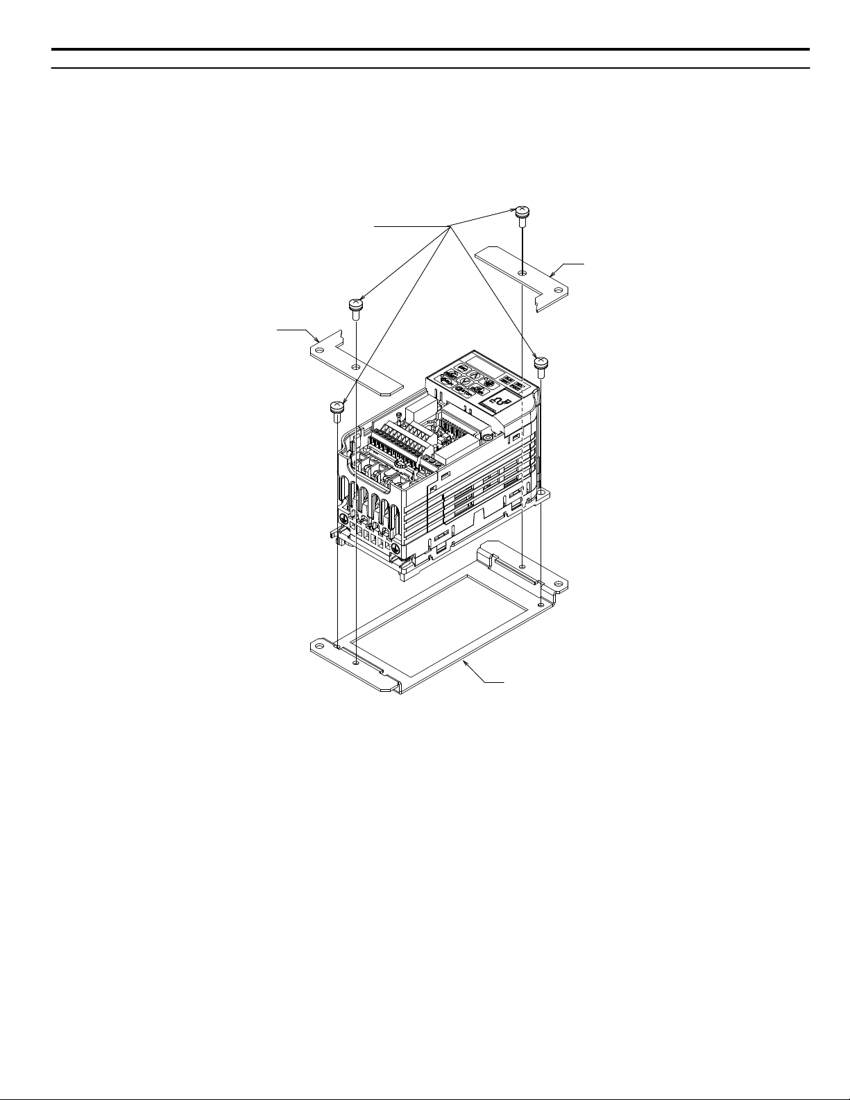
Procedure 1 (Enclosure: IP20)
1. Remove the front cover according to the drive instruction manual.
2. Mount Attachment A to the standard drive mounting legs using the associated M4×10 pan-head screws.
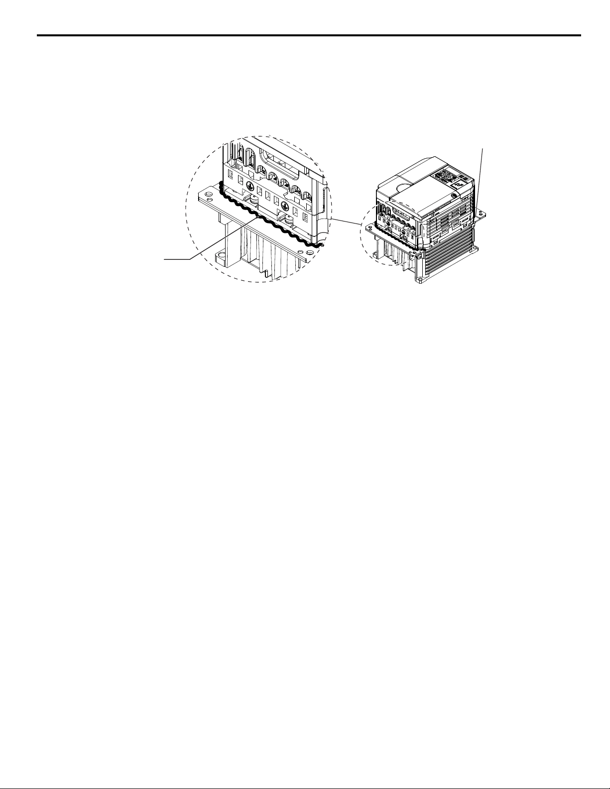
3. Mount Attachment B (2 units) to Attachment A with the associated M4×10 pan-head screws as shown in Figure 3.
4. Reattach the front cover according to the drive instruction manual.
Attachment B
Attachment A
Attachment B
M4x13 Pan-head Screws (x4)
Figure 3 Procedure 1 Diagram (Example Model: CIMR-Vo2o0001)
5 Installation Procedure by Drive Model
YASKAWA V1000/J1000 AC Drive External Heatsink Kit Option Manual EZZ020568
13
n
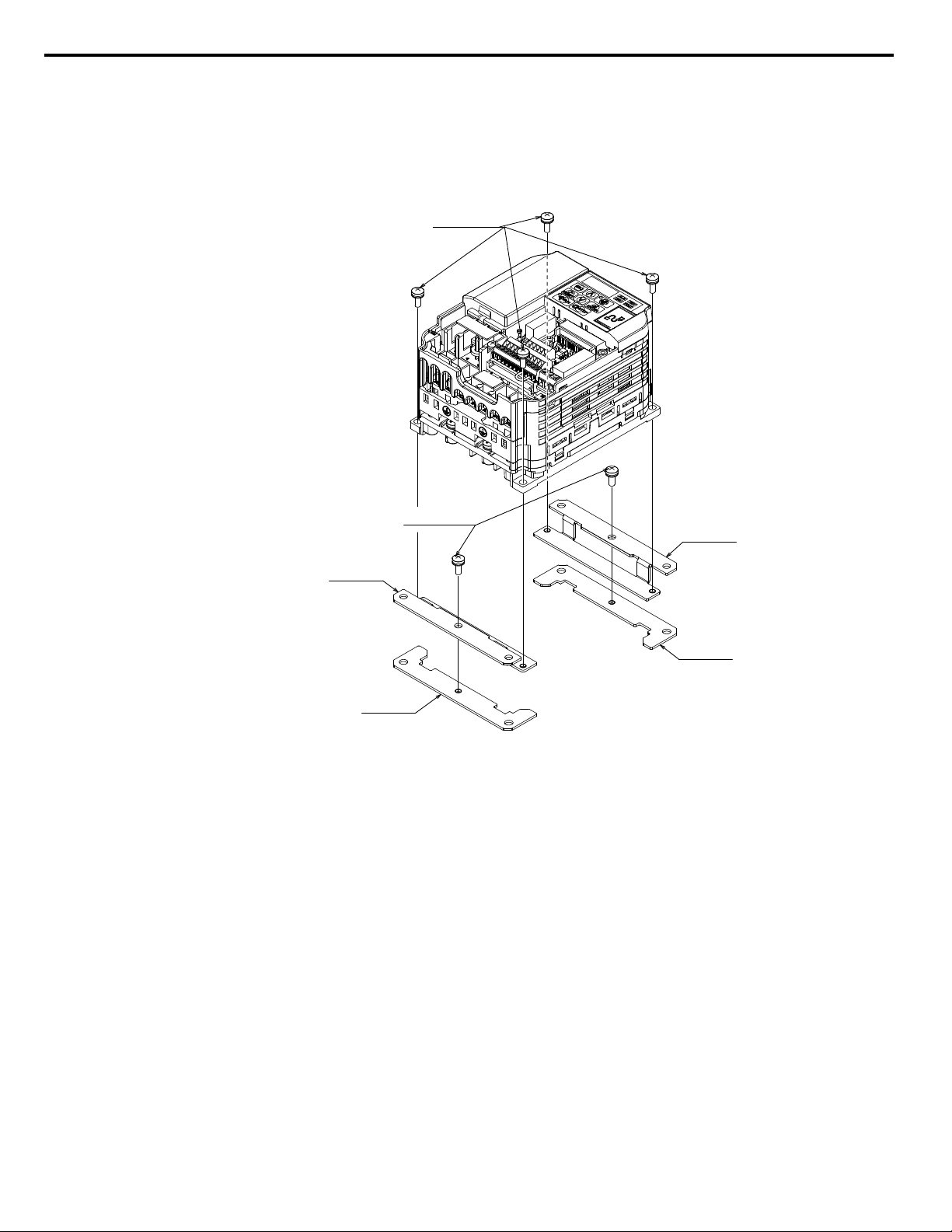
Procedure 2 (Enclosure: IP20)
1. Remove the front cover according to the drive instruction manual.
2. Mount Attachment A (2 units) to the standard inverter mounting legs using the associated M4×10 pan-head screws.
3. Mount Attachment B (2 units) to Attachment A with the associated M4×10 pan-head screws as shown in Figure 4.
4. Reattach the front cover according to the drive instruction manual.
Attachment B
Attachment A
Attachment A
Attachment B
M4 x 10 Pan-head Screws (x4)
M4 x 10 Pan-head Screws (x2)
Figure 4 Procedure 2 Diagram (Example Model: CIMR-Vo4o0001)
5 Installation Procedure by Drive Model
14
YASKAWA V1000/J1000 AC Drive External Heatsink Kit Option Manual EZZ020568
n
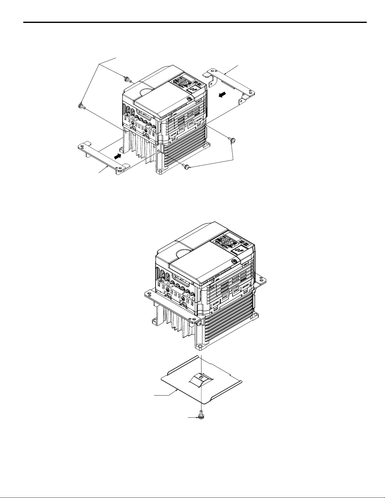
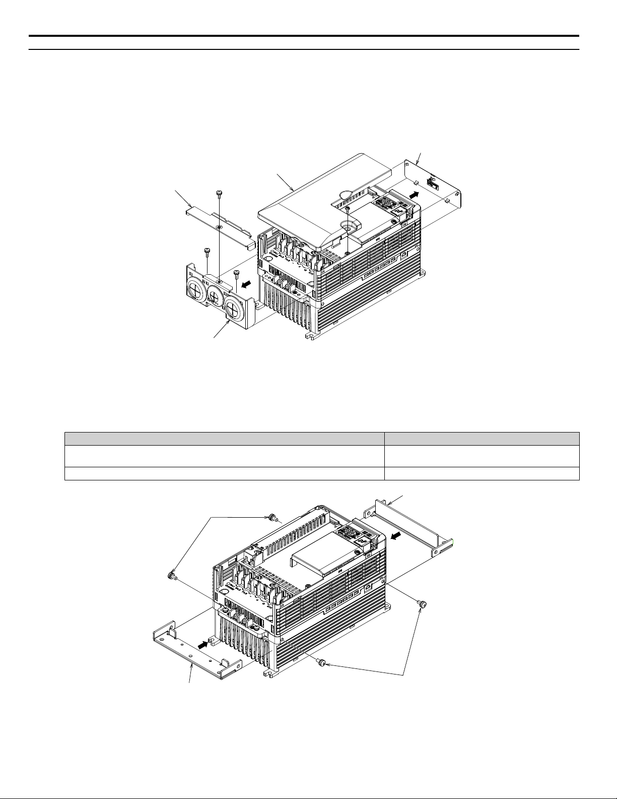
Procedure 3 (Enclosure: IP20)
1. Mount Attachment A (2 each) to the mounting holes on the side of the heatsink using the M4×10 pan-head screws.
Attachment A
M4 x 10 Pan-head Screws (x2)
Attachment A
M4 x 10 Pan-head Screws (x2)
Figure 5 Procedure 3 Diagram (Example Model CIMR-Vo2o0010)
n
Procedure 4 (Enclosure: IP20)
1. Mount the Convective Back Plate to the mounting holes on underside of the heatsink using M4×10 pan-head screws.
M4 x 10 Pan-head Screw
Convective
back plate
Figure 6 Procedure 4 Diagram (Example Model: CIMR-Vo2o0010)
5 Installation Procedure by Drive Model
YASKAWA V1000/J1000 AC Drive External Heatsink Kit Option Manual EZZ020568
15
u
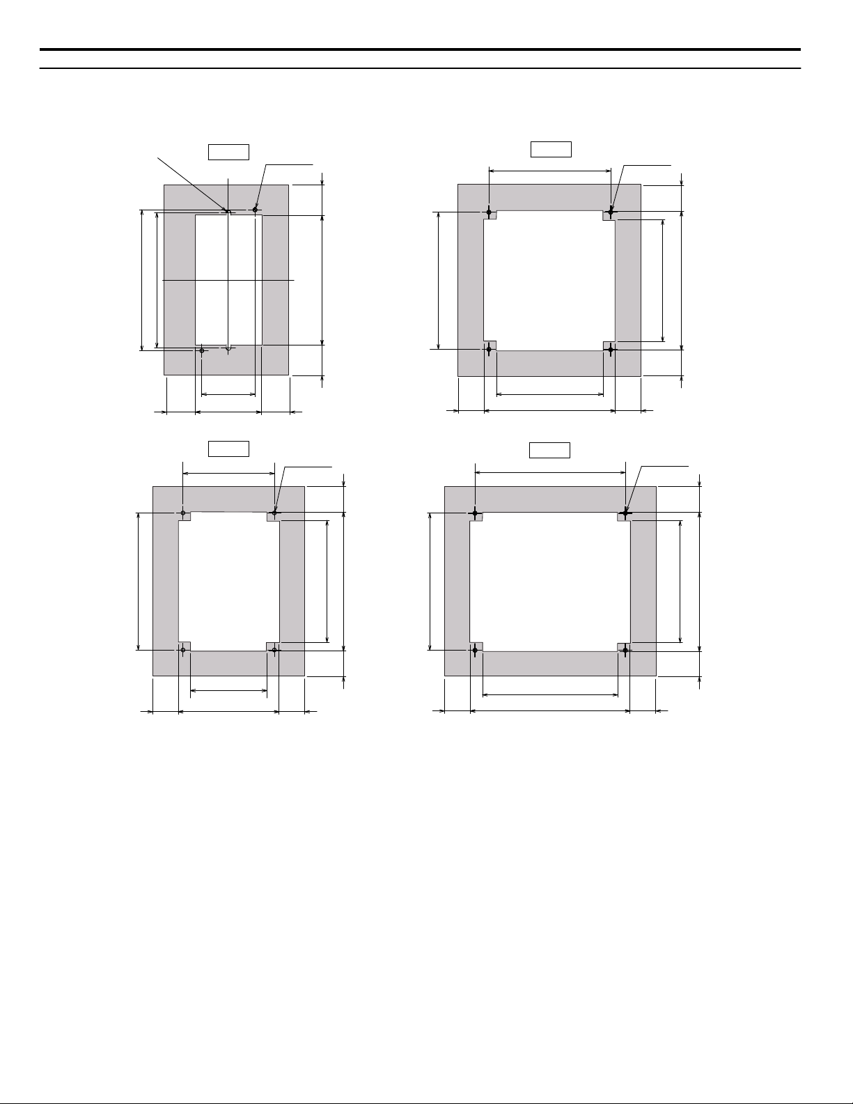
Panel Cutout Dimensions and Optional Gasket (Procedures 1 to 4)
Refer to Table 9 on page 21 to determine the appropriate Panel Cutout and Gasket Drawing below (Fig. A, B, C, or D) for
your specific drive model.
69
(2.7) (1.2)
136
148 (5.8)
142 (5.6)
2-R2.5
112
(4.4)
128
146
(5.7)
138
(5.4)
128
(5.0)
144
128
146
(5.7)
(5.0)
80
(3.1)
106
(4.2)
96
144
(5.7)
(5.7)
128
146
142 (5.6)
168
(6.6)
158
(6.2)
144
32
(1.2)
30.5
30.5
56
2727
27 27
27
27
27
(1.1) (1.1)
27
2727
27 27
(1.1)(1.1)
(1.1)(1.1)
4-M4 Tap
(2-n 5 holes)
4-M4 Tap
(2-n 5 holes)
4-M4 Tap
(2-n 5 holes)
4-M4 Tap
(2-n 5 holes)
(1.3)
32
(1.3)
(5.4)
(5.7)
(2.2)
(2.7)
(1.1)
(1.1)
(5.0)
(1.1)
(1.1)
(1.1)(1.1)
(3.8)
(5.0)
(5.7)
Fig. A
Fig. B
Fig. C
Fig. D
5 Installation Procedure by Drive Model
16
YASKAWA V1000/J1000 AC Drive External Heatsink Kit Option Manual EZZ020568
n
Optional Gasket or Sealant (Procedures 1 to 4)
Note: Gasket or sealant is customer supplied.
If an undesirable air gap exists between Attachment A, B and the drive, attach a CR-Series or EPDM-Series gasket to the
mounting panel surface or apply sealant to fill the gap. Refer to Figure 7 for sealant placement. Refer to Figure A, B, C, or D
for gasket dimensions for your specific model.
Gasket type: CR-Series or EPDM-Series made of foam rubber, approximately 2 mm in thick.
Sealant
Sealant
Figure 7 Sealant Placement
5 Installation Procedure by Drive Model
YASKAWA V1000/J1000 AC Drive External Heatsink Kit Option Manual EZZ020568
17
u
Procedure 5 (Enclosure: NEMA Type 1)
1.
Remove Drive Covers and Brackets
a.
Remove the Terminal Cover.
b.
Remove Top Cover.
c.
Remove NEMA Type 1 Cover.
d.
Remove Conduit Bracket.
NEMA1 Cover
Terminal Cover
Top Cover
Conduit Bracket
Figure 8 Drive Cover and Bracket Removal
2.
Install Attachments 1 and 2
a.
Install Attachment 1 and Attachment 2 to the mounting holes on the side of the heatsink using M5 x12
pan-head screws as shown in Figure 4.
Table 7 Installation Fasteners by Model for Figure 4
Drive Model Installation Fasteners
CIMR-Vo2o0030 to 0056
CIMR-Vo4o0018 to 0038
M5 x 12 Pan-head Screws (x4)
CIMR-Vo2o0069
M6 x 14 Pan-head Screws (x4)
Attachment 1
Attachment 2
M5 x 12 Pan-head Screws (x2)
(screw size varies by model)
M5 x 12 Pan-head Screws (x2)
(screw size varies by model)
Figure 9 Diagram shown for Model CIMR-Vo2o0030
3.
Install Attachment 3
5 Installation Procedure by Drive Model
18
YASKAWA V1000/J1000 AC Drive External Heatsink Kit Option Manual EZZ020568

a.
Install Attachment 3 to the mounting holes of Attachment 1 and Attachment 2 using M4 x10 pan-head
screws.
Attachment 3
M4 x 10 Pan-head Screws (x2)
Figure 10 Attachment 3
4.
Complete the assembly.
a.
Install the terminal cover.
Figure 11 Completed Assembly
5 Installation Procedure by Drive Model
YASKAWA V1000/J1000 AC Drive External Heatsink Kit Option Manual EZZ020568
19
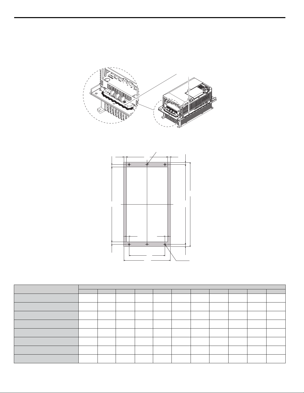
n
Optional Gasket or Sealant (Procedure 5 NEMA Type1 Enclosure)
Note: Gasket or sealant is customer supplied.
If an undesirable gap is found between Attachments 1, 2 or 3 and the drive, attach a CR-Series or EPDM-Series gasket to the
mounting panel surface or apply sealant to fill the gap. Refer to Figure 12 for sealant placement. Refer to Figure 13 for gasket
dimensions.
Gasket type: CR-Series or EPDM-Series made of foam rubber, approximately 2 mm in thick.
Sealant
Figure 12 Sealant Placement
W1
(W)
(H2)
B
H1
(H)
(H3)
(W2) (W2)
4-Md Tap
A
2-n 5 Holes
(W3)(W3)
(H3)
(H2)
Figure 13 Panel Cutout and Optional Gasket Dimensions (Procedure 5 NEMA Type1 Enclosure)
Table 8 Panel Cutout and Optional Gasket Dimensions (Procedure 5 NEMA Type1 Enclosure)
Drive Model CIMR-
Dimensions mm (in)
W H W1 (W2) (W3) H1 (H2) (H3) A B d
Vo2o0030
158
(6.2)
286
(11.3)
122
(4.8)
9
(0.4)
9
(0.4)
272
(10.7)
60
(2.4)
7
(0.3)
140
(5.5)
255
(10.0)
5
(0.2)
Vo2o0040
158
(6.2)
286
(11.3)
122
(4.8)
9
(0.4)
9
(0.4)
272
(10.7)
60
(2.4)
7
(0.3)
140
(5.5)
255
(10.0)
5
(0.2)
Vo2o0056
198
(7.8)
322
(12.7)
160
(6.3)
10
(0.4)
9
(0.4)
308
(12.1)
80
(3.1)
7
(0.3)
180
(7.0)
287
(11.2)
5
(0.2)
Vo2o0069
241
(9.5)
380
(15.0)
192
(7.5)
14
(0.5)
10.5
(0.4)
362
(14.2)
85
(3.3)
9
(0.4)
280
(8.6)
341
(13.4)
5
(0.2)
Vo4o0018
158
(6.2)
286
(11.3)
122
(4.8)
9
(0.4)
9
(0.4)
272
(10.7)
60
(2.4)
7
(0.3)
140
(5.5)
255
(10.0)
5
(0.2)
Vo4o0023
158
(6.2)
286
(11.3)
122
(4.8)
9
(0.4)
9
(0.4)
272
(10.7)
60
(2.4)
7
(0.3)
140
(5.5)
255
(10.0)
5
(0.2)
Vo4o0031
198
(7.8)
322
(12.7)
160
(6.3)
10
(0.4)
9
(0.4)
308
(12.1)
60
(2.4)
7
(0.3)
180
(7.0)
287
(11.2)
5
(0.2)
Vo4o0038
198
(7.8)
322
(12.7)
10
(0.4)
308
(12.1)
9
(0.4)
308
(12.1)
80
(3.1)
7
(0.3)
180
(7.0)
287
(11.2)
5
(0.2)
5 Installation Procedure by Drive Model
20
YASKAWA V1000/J1000 AC Drive External Heatsink Kit Option Manual EZZ020568

6 External Heatsink Option Part Numbers by Drive Model
Table 9 External Heatsink Option Part Numbers (V1000 and J1000 Series Drives)
Drive Model
CIMR-
# = V or J Series
Part
Number
Product Code
72606–
Attachment A Attachment B
Convective
Back Plate
Mounting Screw
Panel
Cutout
and
Gasket
Drawing
(Page 16)
Notes
#oBo0001
#oBo0002
100-034-075 EZZ020568A SPAT35091-1
SPAT45945-1
(×2)
—
M4×10 Pan-head
Screws (×4)
Figure A
<1>
#oBo0003
100-034-076 EZZ020568B SPAT35092-1
SPAT45945-1
(×2)
—
M4×10 Pan-head
Screws (×4)
Figure A
#oBo0006
100-034-076 EZZ020568B SPAT35092-1
SPAT45945-1
(×2)
—
M4×10 Pan-head
Screws (×4)
Figure B
#oBo0010
100-036-418 EZZ020568C SPAT35095-A(×2) — —
M4×10 Pan-head
Screws (×4)
Figure B
#oBo0012
100-034-079 EZZ020568D SPAT35095-A(×2) — SPAT35097-1
M4×10 Pan-head
Screws (×5)
Figure C
#oBo0018
100-034-080 EZZ020568E SPAT35096-A(×2) — SPAT35098-1
M4×10 Pan-head
Screws (×5)
Figure D
#o2o0001
#o2o0002
100-034-075 EZZ020568A SPAT35091-1
SPAT45945-1
(×2)
—
M4×10 Pan-head
Screws (×4)
Figure A
#o2o0004
100-034-076 EZZ020568B SPAT35092-1
SPAT45945-1
(×2)
—
M4×10 Pan-head
Screws (×4)
Figure A
#o2o0006
100-034-077 EZZ020568G SPAT35093-1
SPAT45945-1
(×2)
—
M4×10 Pan-head
Screws (×4)
Figure A
#o2o0008
#o2o0010
#o2o0012
100-034-079 EZZ020568D SPAT35095-A(×2) — SPAT35097-1
M4×10 Pan-head
Screws (×5)
Figure B
#o2o0018
#o2o0020
100-034-080 EZZ020568E SPAT35096-A(×2) — SPAT35098-1
M4×10 Pan-head
Screws (×5)
Figure C
#o4o0001
100-034-078 EZZ020568L SPAT45974-1(×2)
SPAT45975-1
(×2)
—
M4×10 Pan-head
Screws (×4)
Figure B
#o4o0002
#o4o0004
100-036-418 EZZ020568C SPAT35095-A(×2) — —
M4×10 Pan-head
Screws (×5)
Figure B
#o4o0005
#o4o0007
#o4o0009
100-034-079 EZZ020568D SPAT35095-A(×2) — SPAT35097-1
M4×10 Pan-head
Screws (×5)
Figure B
#o4o0011
100-034-080 EZZ020568E SPAT35096-A(×2) — SPAT35098-1
M4×10 Pan-head
Screws (×5)
Figure C
Drive Model
CIMR-
Part
Number
Product Code
72606–
Attachment 1 Attachment 2 Attachment 3 Mounting Screw
Panel
Cutout and
Gasket
Drawing
(Page 20)
Notes
Vo2o0030
Vo2o0040
100-036-300 EZZ020568H SPAT35163-A SPAT35164-A SPAT35165-1
M4×10 Pan-head
Screws (×4)
Figure 13
<1>
Vo2o0056
100-036-301 EZZ020568J SPAT35166-A SPAT35167-A SPAT35168-1
M4×10 Pan-head
Screws (×4)
Vo2o0069
100-036-302 EZZ020568K SPAT35169-A SPAT35170-A SPAT35171-1
M4×10 Pan-head
Screws (×4)
Vo4o0018
Vo4o0023
100-036-300 EZZ020568H SPAT35163-A SPAT35164-A SPAT35165-1
M4×10 Pan-head
Screws (×4)
Vo4o0031
Vo4o0038
100-036-301 EZZ020568J SPAT35166-A SPAT35167-A SPAT35168-1
M4×10 Pan-head
Screws (×5)
<1> Use of this option kit on certain NEMA Type 1 standard drives, requires removal of the drive top cover, NEMA Type 1 cover and conduit bracket.
6 External Heatsink Option Part Numbers by Drive Model
YASKAWA V1000/J1000 AC Drive External Heatsink Kit Option Manual EZZ020568
21

This page intentionally blank
6 External Heatsink Option Part Numbers by Drive Model
22
YASKAWA V1000/J1000 AC Drive External Heatsink Kit Option Manual EZZ020568

7 Revision History
The revision dates and the numbers of the revised manuals appear on the bottom of the back cover.
MANUAL NO. TM.V1000SW.029
Published in U.S.A. March 2013 13-3
Date of
publication
Date of original
publication
Revision number
1
Example:
Date of Publication
Revision
Number
Section Revised Content
September 2013 - - First Edition
7 Revision History
YASKAWA V1000/J1000 AC Drive External Heatsink Kit Option Manual EZZ020568
23

7 Revision History
This Page Intentionally Blank
24
YASKAWA V1000/J1000 AC Drive External Heatsink Kit Option Manual EZZ020568

YASKAWA AMERICA, INC.
2121 Norman Drive South, Waukegan, IL 60085, U.S.A.
Phone: (800) YASKAWA (927-5292) or 1-847-887-7000 Fax: 1-847-887-7310
http://www.yaskawa.com
DRIVE CENTER (INVERTER PLANT)
2-13-1, Nishimiyaichi, Yukuhashi, Fukuoka, 824-8511, Japan
Phone: 81-930-25-3844 Fax: 81-930-25-4369
http://www.yaskawa.co.jp
YASKAWA ELECTRIC CORPORATION
New Pier Takeshiba South Tower, 1-16-1, Kaigan, Minatoku, Tokyo, 105-6891, Japan
Phone: 81-3-5402-4502 Fax: 81-3-5402-4580
http://www.yaskawa.co.jp
YASKAWA ELÉTRICO DO BRASIL LTDA.
Avenda Fagundes Filho, 620 Bairro Saude, São Paulo, SP04304-000, Brasil
Phone: 55-11-3585-1100
Fax: 55-11-5581-8795
http://www.yaskawa.com.br
YASKAWA EUROPE GmbH
Hauptstrasse 185, 65760 Eschborn, Germany
Phone: 49-6196-569-300 Fax: 49-6196-569-398
http://www.yaskawa.eu.com
YASKAWA ELECTRIC UK LTD.
1 Hunt Hill Orchardton Woods, Cumbernauld, G68 9LF, United Kingdom
Phone: 44-1236-735000
Fax: 44-1236-458182
http://www.yaskawa.co.uk
YASKAWA ELECTRIC KOREA CORPORATION
7F, Doore Bldg. 24, Yeoido-dong, Yeoungdungpo-gu, Seoul, 150-877, Korea
Phone: 82-2-784-7844
Fax: 82-2-784-8495
http://www.yaskawa.co.kr
YASKAWA ELECTRIC (SINGAPORE) PTE. LTD.
151 Lorong Chuan, #04-01, New Tech Park, 556741, Singapore
Phone: 65-6282-3003
Fax: 65-6289-3003
http://www.yaskawa.com.sg
YASKAWA ELECTRIC (SHANGHAI) CO., LTD.
No. 18 Xizang Zhong Road, 17F, Harbour Ring Plaza, Shanghai, 200001, China
Phone: 86-21-5385-2200
Fax: 86-21-5385-3299
http://www.yaskawa.com.cn
YASKAWA ELECTRIC (SHANGHAI) CO., LTD. BEIJING OFFICE
Room 1011, Tower W3 Oriental Plaza, No. 1 East Chang An Ave.,
Dong Cheng District, Beijing, 100738, China
Phone: 86-10-8518-4086
Fax: 86-10-8518-4082
YASKAWA ELECTRIC TAIWAN CORPORATION
9F, 16, Nanking E. Rd., Sec. 3, Taipei, 104, Taiwan
Phone: 886-2-2502-5003
Fax: 886-2-2505-1280
In the event that the end user of this product is to be the military and said product is to be employed in any weapons systems or the manufacture
thereof, the export will fall under the relevant regulations as stipulated in the Foreign Exchange and Foreign Trade Regulations. Therefore, be sure
to follow all procedures and submit all relevant documentation according to any and all rules, regulations and laws that may apply.
Specifications are subject to change without notice for ongoing product modifications and improvements.
© 2013 YASKAWA AMERICA, INC. All rights reserved.
Published in U.S.A. September 2013 13-9
MANUAL NO. EZZ020568
0 -0
YASKAWA AMERICA, INC.
YASKAWA AC Drive V/J1000
External Heatsink Attachment
Option Manual