
- 1 -
Technical Support and E-Warranty Certificate www.vevor.com/support
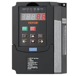
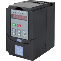
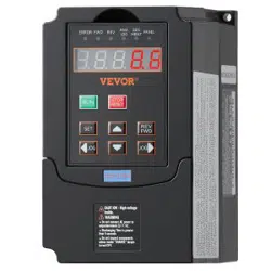
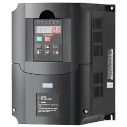
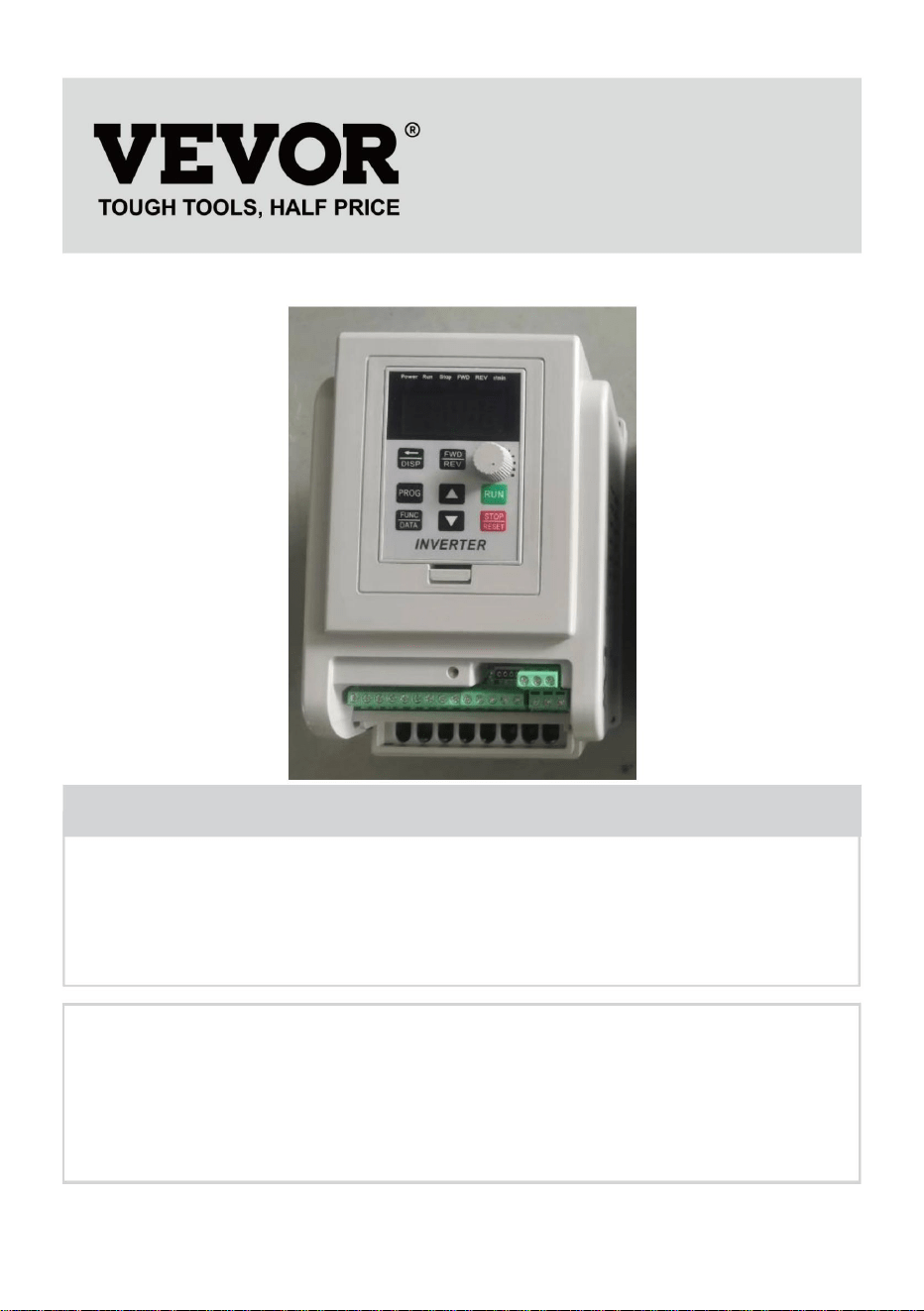
Inverter
MODEL:AT1-4000X
We continue to be committed to provide you tools with competitive price.
"Save Half", "Half Price" or any other similar expressions used by us only represents an
estimate of savings you might benefit from buying certain tools with us compared to the major
top brands and does not necessarily mean to cover all categories of tools offered by us. You
are kindly reminded to verify carefully when you are placing an order with us if you are
actually saving half in comparison with the top major brands.

- 1 -
MODEL:AT1-4000X
Have product questions? Need technical support? Please feel free to
contact us:
Technical Support and E-Warranty Certificate
www.vevor.com/support
NEED HELP? CONTACT US!
This is the original instruction, please read all manual instructions
carefully before operating. VEVOR reserves a clear interpretation of our
user manual. The appearance of the product shall be subject to the
product you received. Please forgive us that we won't inform you again if
there are any technology or software updates on our product.
Inverter

- 2 -
IMPORTANT SAFEGUARDS
Read all safety warnings, instructions, illustrations and
specifications provided with this inverter. Failure to follow all
instructions listed below may result in electric shock, fire
and/or serious injury.
WARNING :
This equipment is a high voltage device, please do not attempt to
disassemble this equipment at any time to avoid danger. After a device
failure, if the external switch fails to restart the device, please contact your
reseller for handling.
WARNING: ELECTRICAL SHOCK AND FIRE HAZARD!
1. Failure to comply with this instruction could result in an electrical failure,
fire and electrocution.
2. DO NOT DISASSEMBLE .
3. Do not submerge inverter .
4. Do not connect two or more transformers in parallel
5. Plug the power supply unit directly into a GFCI wet location outlet .
6. Do not use an extension cord
7. Installation of this inverter and related wiring must be done by aqualified
electrician in compliance with all applicable electrical codes.
WARNING :
Changes or modifications to this unit not expressly approved by the party
responsible for compliance could void the users authority to operate the
equipment .
SAVE THESE INSTRUCTIONS

- 3 -
FCC Information
CAUTION: Changes or modifications not expressly approved by the party
responsible for compliance could void the user's authority to operate the
equipment!
This device complies with Part 15 of the FCC Rules. Operation is subject to
the following two conditions:
1) This product may cause harmful interference.
2) This product must accept any interference received, including
interference that may cause undesired operation.
WARNING: Changes or modifications to this product not expressly
approved by the party.responsible for compliance could void the user's
authority to operate the product.
Note: This product has been tested and found to comply with the limits for
a Class B digital device pursuant to Part 15 of the FCC Rules, These limits
are designed to provide reasonable protection against harmful interference
in a residential installation.
This product generates, uses and can radiate radio frequency energy, and
if not installed and used in accordance with the instructions, may cause
harmful interference to radio communications. However, there is no
guarantee that interference will not occur in a particular installation. If this
product does cause harmful interference to radio or television
reception,which can be determined by turning the product off and on, the
user is encouraged to try to correct the interference by one or more of the
following measures.
Reorient or relocate the receiving antenna.
Increase the distance between the product and receiver.
Connect the product to an outlet on a circuit different from that to which
the receiver is connected.
Consult the dealer or an experienced radio/TV technician for
assistance.
- 4 -
Correct Disposal
This product is subject to the provision of European Directive
2012/19/EC. The symbol showing a wheelie bin crossed
through indicates that the product requires separate refuse
collection in the European Union. This applies to the product
and all accessories marked with this symbol. Products marked as such
may not be discarded with normal domestic waste, but must be taken to a
collection point for recycling electrical and electronic devices.
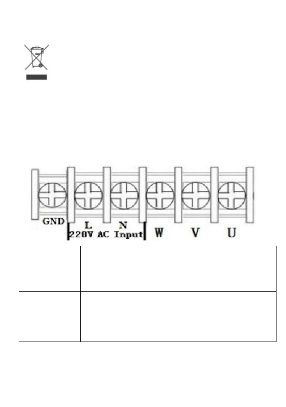
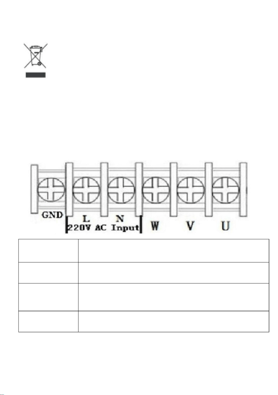
1. Installation and wiring
1.Main circuit terminal and function description
(1)Single-phase to three-phase
Terminal
label
Function description
L,N
Single phase AC 220V input terminal
U,V,W
Output terminal connect to Three phase
220V AC motor
GND
Grounding terminal

- 5 -
2. Terminal description
Port
Functional
description
Instructions
15V
15V power output
200mA15V output
X6
Input port6
(Reversing switch)
Short Port X6 and COM, input signal
effective
X5
Input port 5(Reverse
rotation Control switch)
Short Port X5 and COM, input signal
effective
X4
Input port 4(Forward
rotation Control switch)
Short Port X4 and COM, input signal
effective
X3
Input port 3(section-
speed 3)
Short Port X3 and COM, input signal
effective
X2
Input port 2(section-
speed 2)
Short Port X2 and COM, input signal
effective
X1
Input port 1(section-
speed 1)
Short Port X1 and COM, input signal
effective
485+/485-
485 communication port
Optional, only for special model
COM
Common GND
VL1
External analog voltage
input
0-5/10 V Analog voltage input
CI
External current signal
input
4-20mA Current input
SP1
Open-collector output 1
5V
5V power output
supply 5V 20mA power output
TC
Relay output C
250VAC 5A/30VDC 3A
TA and TB Normal Close ,TA and TC
Normal Open
TB
Relay output B
TA
Relay output A

- 6 -
3. Multi-speed input Frequency control table :
Section
speed input 1
Section
speed input 2
Section
speed input 3
Original
Frequency
Main Speed
1
1
1
50
Section speed 1
0
1
1
45
Section speed 2
1
0
1
40
Section speed 3
0
0
1
35
Section speed 4
1
1
0
30
Section speed 5
0
1
0
25
Section speed 6
1
0
0
20
Section speed 7
0
0
0
15
Note :
0 means input Port connect with COM, 1 means
disconnect.

- 7 -
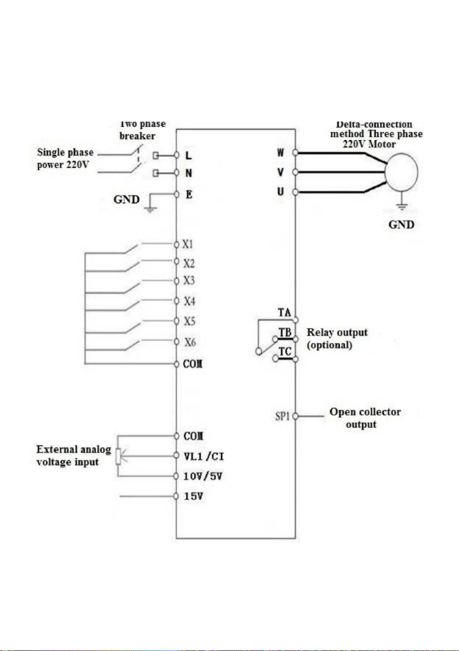
4. Basic operation wiring diagram
(1) Single-phase input three-phase output
(Three phase 220V, if 380V Star-connection method needs to change to
the 220V Delta-connection method)

- 8 -
5. Operation panel
- 9 -
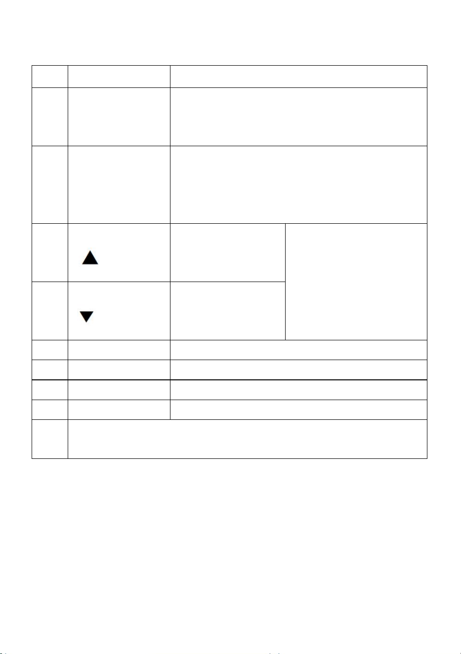
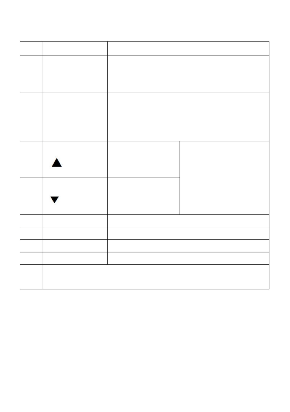
6. Keys instructions :
Icon
Function description
1
(Programming)
For selecting mode or Programming mode (it is
available not mater the Inverter star or stop),
press this key for modifying parameters.
2
(Function/ Save)
Function data setting key. Normal mode: press this
key to display the information of the Inverter,such
as target frequency, output frequency and
current, temperature;
3
Key
( )
Parameter
number or parameter
value increase
Short press this key, then
the numerical value will
change gradually. Long
press this key, then the
numerical value will
change rapidly
4
Key
( )
Parameter
number or parameter
value decrease
5
Shift
Shift in programming mode, jog in normal mode
6
Forward/ Reverse
Forward/ Reverse switching key
7
Start
Start Inverter output
8
Stop / Reset
Break down,fault resetting
Note
Please modify the parameters under the stop state, otherwise the
changed parameters cannot be saved.

- 10 -
7. Parameter specification
1. Parameter specification
Parameter
Parameter
specification
Parameter range
Default
Unit
P00
Maximum voltage
0---220.0/380.0
220/380
V
P01
Reference frequency
0---400.0
50
Hz
P02
Intermediate voltage
0---220.0/380.0
110/190
V
P03
Intermediate
frequency
0---400.0
25
Hz
P04
Minimum voltage
0---220.0/380.0
0
V
P05
Minimum frequency
0---400.0
0
Hz
P06
Maximum operating
0---400.0
65.0
Hz
P07
Minimum operating
0---400.0
0
Hz
P08
Hide password
0---65535
00000
P09
Input password
0---65535
0
P10
Working frequency
source
0: Panel keyboard;
1: Panel
potentiometer;2:
External analog
signal4: RS485.
1
P11
Start/stop
control source
0:Panel keyboard;
1:RS485;
2:External port.
0
P12
Stopping Modes
0:Inertial stop;
1:Deceleration
stop;
2: Brake stop;
3:Emergency
brake.
1
P13
Braking time
0---2.5
0.5
S
P14
Braked Voltage
0---140.0
20
V

- 11 -
P17
Machine number
1-255
1
P18
Operating arrival
0---100.0
50
Hz
P20
Over temperature
protection selection
1---80
80
P21
Revolution for 50Hz
0-8000
2800
P22
Carrier setting
1---20
10
P23
Frequency adjusting
step size
1---100
5
0.1Hz
P24
Overload protection
buffer time
0.1---60.0
3
S
P26
Working frequency
0---400.0
50
Hz
P27
Section speed 1 setting
0---400.0
45
Hz
P28
Section speed 2 setting
0---400.0
40
Hz
P29
Section speed 3 setting
0---400.0
35
Hz
P30
Section speed 4 setting
0---400.0
30
Hz
P31
Section speed 5 setting
0---400.0
25
Hz
P32
Section speed 6 setting
0---400.0
20
Hz
P33
Section speed 7 setting
0---400.0
15
Hz
P34
Main rising velocity
1---1000
25
Hz/S
P35
1st rising velocity
1---1000
25
Hz/S
P36
2nd rising velocity
1---1000
25
Hz/S
P37
3rd rising velocity
1---1000
25
Hz/S
P38
4th rising velocity
1---1000
25
Hz/S
P39
5th rising velocity
1---1000
25
Hz/S
P40
6th rising velocity
1---1000
25
Hz/S
P41
7th rising velocity
1---1000
25
Hz/S
P42
Main descent velocity
1---1000
25
Hz/S
P43
1st descent velocity
1---1000
25
Hz/S
P44
2nd descent velocity
1---1000
25
Hz/S
P45
3rd descent velocity
1---1000
25
Hz/S
P46
4th descent velocity
1---1000
25
Hz/S
P47
5th descent velocity
1---1000
25
Hz/S
P48
6th descent velocity
1---1000
25
Hz/S

- 12 -
P49
7th descent velocity
1---1000
25
Hz/S
P50
Multi function input 1
(X1 binding post)
0:invalid,terminal is
non-functioning
1:wire control stop
2:keying stop;
3:keying operation;
4:stop keying;
5:wire forward
operation
6: wire reverse
operation;
7: reservation
8: error reset
signal;
9: wire reversing
switch;
10:keying forward
switching;
11:keying forward
switching;
12: reverse switch
keying;
13: section speed
input 1;
14:section speed
input 2;
15: section speed
input 3;
16: external error
signal.
17: Jog Forward;
18: Jog Reverse;
19: Emergency
stop;
13
P51
Multi function input 2
14
P52
Multi function input 3
15
P53
Multi function input 4
5
P54
Multi function input 5
6
P55
Multi function input 6
9

- 13 -
20:Relay Control.
P58
Multi function input 1
(SP1)
0: invalid, no
output;
1:operating
instructions;
2: set arrival
instructions
3: fault indication;
5: Emergency stop;
6: For
P50---P55=20;
0
P60
Multi function input 2
Idem (Relay output)
0
P62
Display options
0: setting
frequency;
1: operating
frequency;
2: revolution 3:
current;
4: temperature; 5:
time;
0
P65
Power on options
0: normal power on;
1:report error with
start signal;
2:Power on
forward;
3:Power on
reverse.
0
P66
Input stabilization time
0---65535
60
mS
P67
Voltage coefficient
0---65535
28500
P68
Under voltage setting
0---220/380
60/180
V
P69
Over voltage setting
220.0---400/680
400/600
V

- 14 -
P70
Torque compensation
options
0:P72 is
compensation
amount;
1: Multiply P72 by
P71 after P71
minus input voltage
0
P71
Torque compensation
voltage
0---300.0
10
V
P72
Torque compensation
setting
0---100
0
P73
Maximum external
analog
0---65535
31440
P74
Minimum external
analog
0---65535
2096
P75
Zero current
compensation value
0---65535
1130
P76
Current coefficient
0---65535
42000
P77
Parameter reset
0---65535
(It is the reset when
54321)
0
P78
Main current overload
0-65535
20000
mA
P79
First current overload
0-65535
20000
mA
P80
Second current overload
0-65535
20000
mA
P81
Third current overload
0-65535
20000
mA
P82
Fourth current overload
0-65535
20000
mA
P83
Fifth current overload
0-65535
20000
mA
P84
Sixth current overload
0-65535
20000
mA
P85
Seventh current
overload
0-65535
20000
mA
P86
Jog forward frequency
0---400.0
20
Hz
P87
Jog reverse frequency
0---400.0
20
Hz
P88
Jog rising velocity
1---1000
50
Hz/S
P89
Jog descent velocity
1---1000
50
Hz/S

- 15 -
P90
Jog stopping modes
0:Inertia stop;
1:Decelerate stop;
2:Braking stop;
3:Emergency
brake.
1
P91
Jog braking time
0---2.5
0.1
S
P124
Fan start temperature
=0 Fan running
when
VFD starts
0
℃
P127
Remaining hours
0---65535
65535
H
2. Parameter setting password and Down time stop:
P08 is the hidden password, it always shows only 00000, not the actual
value.
When input the value of P09=the hidden value of P08, the P08 shows
hidden value, and the P08 and other parameters can be changed. The P09
will be nullified when unplug the power cable to restart.
When P127=65535,the function of countdown do not start.
When P127 < 65535,the function of countdown will start, the P127 will
minus 1 when the Inverter runs for one hour. The frequency converter will
be stopped when the countdown of P127 to 0 hour.
8. Parameter setting procedure:
1. Press the programming key to enter into the programming state;
2.Use the arrow keys and shift key to find the parameters that need to be
modified;
3.Press function/save key to enter into the parameter;
4.Use the arrow keys and shift key to amend the parameter value;
5.Press the function/ save key to store the parameter;
6. Press the programming key to exit the programming state.
Chapter 4 Fault Code

- 16 -
Fault Code Display
Fault Code Description
Err 1
Short Circuit/Current overload/Power
Module protection
Err 2
Under voltage protection
Err 3
Over voltage protection
Err 4
Driving Circuit Failures
Err 5
Input at startup when electrified
Err 6
Over current protection
Err 7
Overtime
Err 8
Excessive temperatures for radiator
Err 9
External fault
Made In China


MODÈLE:AT14000X
1
Onduleur
Assistancetechniqueetcertificatdegarantieélectroniquewww.vevor.com/support
«Économisezlamoitié»,«Moitiéprix»outouteautreexpressionsimilaireutiliséeparnousnereprésente
qu'uneestimationdeséconomiesquevouspourriezréaliserenachetantcertainsoutilscheznousparrapport
auxgrandesmarquesetnecouvrepasnécessairementtouteslescatégoriesd'outilsquenousproposons.
Nousvousrappelonsdebienvouloirvérifiersoigneusementlorsquevouspassezunecommandechez
noussivouséconomisezréellementlamoitiéparrapportauxgrandesmarques.
Nouscontinuonsànousengageràvousfournirdesoutilsàdesprixcompétitifs.
Machine Translated by Google

BESOIND'AIDE?CONTACTEZNOUS!
Vousavezdesquestionssurnosproduits?Vousavezbesoind'assistancetechnique?
N'hésitezpas
ànouscontacter:Assistancetechniqueetcertificatdegarantie
électroniquewww.vevor.com/support
MODÈLE:AT14000X
Ils'agitdelanoticed'utilisationd'origine.Veuillezlireattentivementtoutesles
instructionsdumanuelavantdel'utiliser.VEVORseréserveledroitd'interpréterclairement
notremanueld'utilisation.L'apparenceduproduitdépendduproduitquevousavez
reçu.Veuilleznousexcuser,nousnevousinformeronsplusencasdemiseàjourtechnologique
oulogicielledenotreproduit.
Onduleur
1
Machine Translated by Google

et/oudesblessuresgraves.
2.NEPASDÉMONTER.
responsabledelaconformitépourraitannulerl'autoritédesutilisateursàexploiterle
AVERTISSEMENT:
3.Nepasimmergerl’onduleur.
équipement.
spécificationsfourniesaveccetonduleur.Lenonrespectdetoutesles
1.Lenonrespectdecetteinstructionpeutentraînerunepanneélectrique,
AVERTISSEMENT:
lesinstructionsénuméréescidessouspeuvententraînerunchocélectrique,unincendie
incendieetélectrocution.
panne,silecommutateurexterneneparvientpasàredémarrerl'appareil,veuillezcontactervotre
6.N'utilisezpasderallonge
Leschangementsoumodificationsapportésàcetteuniténonexpressémentapprouvésparleparti
revendeurpourlamanutention.
7.L'installationdecetonduleuretlecâblageassociédoiventêtreeffectuésparuntechnicienqualifié.
Liseztouslesavertissementsdesécurité,instructions,illustrationset
AVERTISSEMENT:RISQUEDECHOCÉLECTRIQUEETD’INCENDIE!
Cetéquipementestunappareilàhautetension,veuilleznepastenterde
4.Neconnectezpasdeuxouplusieurstransformateursenparallèle
électricienenconformitéavectouslescodesélectriquesapplicables.
démontezcetéquipementàtoutmomentpourévitertoutdanger.Aprèsunappareil
5.Branchezleblocd'alimentationdirectementsurunepriseGFCIpourendroithumide.
CONSERVEZCESINSTRUCTIONS
MESURESDESÉCURITÉIMPORTANTES
2
Machine Translated by Google

Consultezlerevendeurouuntechnicienradio/TVexpérimentépour
Cetappareilestconformeàlapartie15desrèglesdelaFCC.Sonfonctionnementestsoumisà
unappareilnumériquedeclasseBconformémentàlapartie15desrèglesdelaFCC.Ceslimites
l'utilisateurestencouragéàessayerdecorrigerl'interférenceparuneouplusieursdes
lesdeuxconditionssuivantes:
sontconçuspourfourniruneprotectionraisonnablecontrelesinterférencesnuisibles
mesuressuivantes.
Réorienteroudéplacerl'antennederéception.Augmenter
ladistanceentreleproduitetlerécepteur.Connecterleproduitàuneprise
suruncircuitdifférentdeceluiauquelilestconnecté.
responsabledelaconformitépourraitannulerl'autoritédel'utilisateuràexploiterle
autorisationd'exploiterleproduit.
leproduitprovoquedesinterférencesnuisiblesaveclaradiooulatélévision
équipement!
Remarque:Ceproduitaététestéetjugéconformeauxlimitesde
interférencespouvantentraînerunfonctionnementindésirable.
s'iln'estpasinstalléetutiliséconformémentauxinstructions,peutprovoquer
réception,quipeutêtredéterminéeenéteignantetenrallumantleproduit,le
AVERTISSEMENT:Leschangementsoumodificationsapportésàceproduitnonexpressément
interférencesnuisiblesauxcommunicationsradio.Cependant,iln'existeaucune
assistance.
ATTENTION:Leschangementsoumodificationsnonexpressémentapprouvésparlapartie
approuvéparleparti.responsabledelaconformitépourraitannulerl'autorisationdel'utilisateur
1)Ceproduitpeutprovoquerdesinterférencesnuisibles.
dansuneinstallationrésidentielle.
garantirqu'aucuneinterférenceneseproduiradansuneinstallationparticulière.Sicela
2)Ceproduitdoitacceptertouteinterférencereçue,ycompris
Ceproduitgénère,utiliseetpeutémettredel'énergieradiofréquence,et
lerécepteurestconnecté.
InformationsdelaFCC
3
Machine Translated by Google
1.Installationetcâblage1.
Borneducircuitprincipaletdescriptiondela
fonction(1)Monophaséàtriphasé
4
L,N
Borned'entréemonophaséeCA220V
Bornedesortieconnectéeautriphasé
Moteuràcourantalternatif220V
Terminal
Descriptiondelafonction
étiquette
Ceproduitestsoumisauxdispositionsdeladirectiveeuropéenne2012/19/
CE.Lesymbolereprésentantunepoubellebarréeindiquequele
produitdoitfairel'objetd'unecollectesélectivedesdéchetsdansl'Union
européenne.Celas'appliqueauproduitetàtouslesaccessoiresmarqués
decesymbole.Lesproduitsmarquéscommetelsnepeuventpasêtrejetésavecles
orduresménagèresnormales,maisdoiventêtredéposésdansunpointdecollectepourle
recyclagedesappareilsélectriquesetélectroniques.
U,V,W
Terre
Bornedemiseàlaterre
Éliminationcorrecte
Machine Translated by Google

PortcourtX2etCOM,signald'entrée
Entréedecourant420mA
Portd'entrée6
Puissancedesortie15V
efficace
Tensionanalogiqueexterne
FermeturenormaleTAetTB,TAetTC
Portd'entrée4(transfert)
PortcourtX1etCOM,signald'entrée
SortierelaisC
Sortie200mA15V
X4
VL1
Portd'entrée1(section
vitesse1)
Enoption,uniquementpourlemodèlespécial
alimentation5V20mAsortied'alimentation
(Interrupteurd'inversion)
SP1
efficace
Port
PortcourtX4etCOM,signald'entrée
saisir
Ouverturenormale
Interrupteurdecommandederotation)
efficace
SortierelaisB
PortcourtX6etCOM,signald'entrée
PortcourtX3etCOM,signald'entrée
Entréedetensionanalogique05/10V
Fonctionnel
AVEC
250VCA5A/30VCC3A
X6
Portd'entrée5(inverse)
X3
Sortieàcollecteurouvert1
Instructions
efficace
Signaldecourantexterne
tuberculose
Portd'entrée3(section
vitesse3)
SortierelaisA
X1
efficace
efficace
LÀ
description
PortcourtX5etCOM,signald'entrée
GNDcommun
TC
Interrupteurdecommandederotation)
X2
Puissancedesortie5V
15V
X5
saisir
PAREMENT
Portd'entrée2(section
vitesse2)
Portdecommunication485+/485485
5V
2.Descriptionduterminal
5
Machine Translated by Google

1 1
1
1
0
50
30
Original
entréedevitesse2
1
Section
35
0signifiequeleportd'entréeestconnectéàCOM,1signifie
Vitessedelasection5
40
0
Vitessedelasection3
Vitessedelasection7
0
1
20
0
Vitessedelasection2
Vitesseprincipale
1
0
0 25
1
entréedevitesse1
1
entréedevitesse3
déconnecter.
Vitessedelasection6
15
Vitessedelasection4
Section
0
0
0
Section
1
0
1
0
45
1
Vitessedelasection1
0
Fréquence
Note:
3.Tableaudecontrôledefréquenced'entréemultivitesses:
6
Machine Translated by Google

(Triphasé220V,silaméthodedeconnexionenétoile380Vdoitêtreremplacéeparla
méthodedeconnexionentriangle220V)
(1)Entréemonophasée,sortietriphasée
4.Schémadecâblagedufonctionnementdebase
7
Machine Translated by Google

8
5.Panneaudecommande
Machine Translated by Google
Touchedecommutationmarcheavant/arrière
touchepourafficherlesinformationsdel'onduleur,tellesque
Paramètre
Touchederéglagedesdonnéesdefonction.Modenormal:appuyezsurcettetouche
changerprogressivement.Long
Commencer
)
8
disponiblepeuimportel'onduleurenmarcheouenarrêt),
lavaleurnumériquesera
Changement
Clé
6
(Fonction/Enregistrer)
4
Note
nombreouparamètre
(Programmation)
)
Paramètre
Veuillezmodifierlesparamètressousl'étatd'arrêt,sinonle
Panne,réinitialisationdesdéfauts
commefréquencecible,fréquencedesortieet
Icône
appuyezsurcettetouche,puissurla
Clé
augmentationdevaleur
Changementenmodeprogrammation,joggingenmodenormal
(
appuyezsurcettetouchepourmodifierlesparamètres.
7
5
lesparamètresmodifiésnepeuventpasêtreenregistrés.
Poursélectionnerlemodeoulemodedeprogrammation(ilest
nombreouparamètre
changerrapidement
2
Descriptiondelafonction
Appuyezbrièvementsurcettetouche,puis
diminutiondevaleur
courant,température;
lavaleurnumériquesera
1
(
Arrêter/Réinitialiser
3
Démarrerlasortiedel'onduleur
6.Instructionspourlestouches:
9
Machine Translated by Google

0220,0/380,0
P09
fréquence
2:Portexterne.
P13
Paramètre
Intermédiaire
Fréquencedetravail
0
3:Urgence
Tensionmaximale
0400,0
Minimumd'exploitation
source
0,5
Plagedeparamètres
P06
00000
signal4:RS485.
frein.
50
0:Clavierdupanneau;
Hz
0
Défaut
0400,0
Tensionminimale
0:Arrêtinertiel;
P14
P00
P03
0
P10
P12
Fréquencederéférence
0400,0
Masquerlemotdepasse
Démarrer/arrêter
20
0220,0/380,0
P07
0
0:Clavierdupanneau;
02,5
Hz
1:Panneau
Hz
arrêt;
Unité
0220,0/380,0
Fréquenceminimale
1:Décélération
Tempsdefreinage
P01
P04
65,0
potentiomètre;2:
Modesd'arrêt
Tensionintermédiaire
065535
Entrerlemotdepasse
sourcedecontrôle
S
0400,0
P08
Hz
1:RS485;
0140,0
Paramètre
110/190V
25
Hz
2:Arrêtdefrein;
spécification
0400,0
Capacitédefonctionnementmaximale
1
Tensionfreinée
P02
0
P05
Analogiqueexterne
1
220/380V
065535
V
P11
V
1.Spécificationdesparamètres
7.Spécificationdesparamètres
10
Machine Translated by Google

11
Hz
P36
25
1
11000
0400,0
P29
Hz
P22
Hz/s
30
Hz/s
Réglagedelavitessedelasection1
Sélectiondeprotection
contrelasurchauffe
P43
25
11000
11000
25
0400,0
P28
Vitesseascendanteprincipale
1èrevitesseascendante
2èmevitesseascendante
3èmevitesseascendante
4èmevitesseascendante
5èmevitesseascendante
6èmevitesseascendante
7èmevitesseascendante
P24
Hz
35
Fréquencedetravail
Arrivéeopérationnelle
Hz/s
11000
Hz/s
P42
P35
0100,0
P27
25
0400,0
Réglagedelavitessedelasection7
25
0,1Hz
P21
5
Hz
11000
Hz/s
P41
P34
1255
Hz/s
11000
0400,0
Réglagedelavitessedelasection6
25
Protectioncontrelessurcharges
Hz/s
40
1100
P48
11000
25
P40
Numérodemachine
P33
Hz
Hz
11000
P26
Hz/s
Réglagedelavitessedelasection5
Tailledupasderéglagede
lafréquence
P47
25
120
Hz/s
10
45
P20
25
11000
P32
tempstampon
25
Hz
0400,0
P46
08000
Hz/s
2800
50
15
11000
Hz/s
P39
11000
P31
S
25
25
0400,0
Réglagedutransporteur
Réglagedelavitessedelasection4
Hz
P45
180
11000
11000
80
P38
Hz/s
P18
3
Hz/s
20
0400,0
Révolutionpour50Hz
25
25
Réglagedelavitessedelasection3
11000
P37
Hz
50
P17
11000
0400,0
P30
Hz/s
Hz/s
0,160,0
Vitessededescenteprincipale
1èrevitessededescente
2èmevitessededescente
3èmevitessededescente
4èmevitessededescente
5èmevitessededescente
6èmevitessededescente
P23
25
Réglagedelavitessedelasection2
P44
25
Machine Translated by Google

12
0:invalide,leterminalest
opération
entrée1;
7èmevitessededescente
P53
commutation;
3:opérationdesaisie;
8:réinitialisationd'erreur
entrée3;
Entréemultifonction3
5
9
P49
13
10:toucheavant
18:JogReverse;
nonfonctionnel
6:filinversé
14:vitessedesection
Entréemultifonction1
P54
12:interrupteurdemarchearrière
4:arrêterlasaisie;
signal;
16:erreurexterne
Entréemultifonction4
6
saisie;
P50
P51
commutation;
19:Urgence
1:arrêtdecontrôledefil
opération;
entrée2;
(bornedeliaisonX1)
14
P55
25
9:inversiondefil
signal.
Entréemultifonction5
5:filenavant
13:vitessedelasection
11000
P52
11:toucheavant
arrêt;
2:arrêtdeclavetage;
7:réservation
15:vitessedelasection
Entréemultifonction2
Entréemultifonction6
15
Hz/s
changer;
17:Jogenavant;
Machine Translated by Google

13
2:révolution3:
P50P55=20;
P62
Entréemultifonction1
0
signaldedépart;
Optionsdemisesoustension
P67
1:fonctionnement
5:Arrêtd’urgence;
1:enfonctionnement
0:misesoustensionnormale;
28500
inverse.
0220/380
Réglagedesurtension
P58
P60
actuel;
sortir;
3:indicationdedéfaut;
fréquence;
P65 0
Tempsdestabilisationd'entrée
2:arrivéeprévue
Idem(Sortierelais)
0
Réglagedesoustension
MS60
Optionsd'affichage
2:Misesoustension
P68
(SP1)
Entréemultifonction2
60/180V
temps;
3:Misesoustension
instructions;
6:Pour
fréquence;
1:signaleruneerreuravec
P66
20:Contrôledurelais.
0:nonvalide,non
0
065535
400/600V
4:température;5:
0:réglage
avant;
065535
220,0400/680
Coefficientdetension
P69
instructions
Machine Translated by Google

14
0
P73
0
065535
FréquencedemarchearrièreJog
Hz
1:MultipliezP72par
Externemaximum
065535
Deuxièmesurchargedecourant065535
065535
paramètre
065535
P81
20000mA
0400,0
Compensationdecouple
Courantnul
(C'estlaréinitialisationlorsque
Cinquièmesurchargedecourant
P88
0:P72est
P72
1130
Surchargeducourantprincipal
20000mA
20
Hz
Compensationdecouple
065535
P78
Septièmecourant
Jogàvitessecroissante
P71aprèsP71
analogique
42000
Troisièmesurchargedecourant
20000mA
P71
2096
P82
20000mA
11000
options
valeurdecompensation
54321)
065535
P89
compensation
0100
P76
Premièresurchargedecourant
20000mA
50
tension
31440
P79
surcharge
Vitessededescenteenjogging
tensiond'entréenégative
Minimumexterne
P77
065535
P86
10
P75
P83
20000mA
11000
P70
Coefficientdecourant
065535
Sixièmesurchargedecourant
Fréquencedejoggingenavant
Hz/s
montant;
0
065535
065535
P85
50
Compensationdecouple
P74
P80
20000mA
0400,0
0300,0
Réinitialisationdesparamètres
analogique
Quatrièmecourantdesurcharge065535
P87
V
065535
P84
20000mA
20
Hz/s
Machine Translated by Google

LorsqueP127=65535,lafonctiondecompteàreboursnedémarrepas.
4.UtilisezlestouchesfléchéesetlatoucheMajpourmodifierlavaleurduparamètre;
LorsqueP127<65535,lafonctiondecompteàreboursdémarre,leP127
5.Appuyezsurlatouchedefonction/enregistrerpourenregistrerleparamètre;
LorsquevousentrezlavaleurdeP09=lavaleurcachéedeP08,leP08s'affiche
2.UtilisezlestouchesfléchéesetlatoucheMajpourtrouverlesparamètresàmodifier.
valeurcachée,etleP08etd'autresparamètrespeuventêtremodifiés.LeP09
modifié;
seraannulélorsquevousdébrancherezlecâbled'alimentationpourredémarrer.
3.Appuyezsurlatouchefonction/enregistrerpouraccéderauparamètre;
P08estlemotdepassecaché,ilaffichetoujoursuniquement00000,paslemotdepasseréel
valeur.
1.Appuyezsurlatouchedeprogrammationpourentrerdansl’étatdeprogrammation;
moins1lorsquel'onduleurfonctionnependantuneheure.Leconvertisseurdefréquence
6.Appuyezsurlatouchedeprogrammationpourquitterl'étatdeprogrammation.
êtrearrêtélorsquelecompteàreboursdeP127à0heure.
15
Chapitre4Coded'erreur
2.Motdepassederéglagedesparamètresetarrêtdutempsd'arrêt:
P90
P91
Heuresrestantes
Modesd'arrêtdujogging
Tempsdefreinageenjogging
65535
2:Arrêtdefreinage;
DémarrageduVFD
0
3:Urgence
065535
02,5
°C
P127
0:Arrêtparinertie;
=0Ventilateurenmarche
P124
1:Arrêtdécélération;
quand
1
0,1
Températurededémarrageduventilateur
frein.
S
H
8.Procédurederéglagedesparamètres:
Machine Translated by Google

FabriquéenChine
Erreur1
Erreur4
Erreur2
Erreur5
Courtcircuit/Surchargedecourant/Alimentation
Aufildutemps
Défautexterne
Protectiondesmodules
Erreur3
Pannesducircuitdeconduite
Erreur8
Affichagedescodesd'erreur
Entréeaudémarragesoustension
Températuresexcessivespourleradiateur
Protectioncontrelessurintensités
Descriptionducoded'erreur
Protectioncontrelessoustensions
Erreur6
Erreur9
Protectioncontrelessurtensions
Erreur7
16
Machine Translated by Google


MODELL:AT1-4000X
Wechselrichter
Technischer Support und E-Garantie-Zertifikat www.vevor.com/support
- 1 -
„Sparen Sie die Hälfte“, „Halber Preis“ oder andere ähnliche Ausdrücke, die wir verwenden, stellen nur eine
Schätzung der Ersparnis dar, die Sie beim Kauf bestimmter Werkzeuge bei uns im Vergleich zu den großen
Topmarken erzielen können, und decken nicht unbedingt alle von uns angebotenen Werkzeugkategorien ab. Wir
möchten Sie freundlich daran erinnern, bei Ihrer Bestellung bei uns sorgfältig zu prüfen, ob Sie im Vergleich
zu den großen Topmarken tatsächlich die Hälfte sparen.
Wir sind weiterhin bestrebt, Ihnen Werkzeuge zu wettbewerbsfähigen Preisen anzubieten.
Machine Translated by Google
Haben Sie Fragen zum Produkt? Benötigen Sie technischen Support? Bitte kontaktieren Sie
uns:
Technischer Support und E-Garantie-Zertifikat www.vevor.com/
support
MODELL:AT1-4000X
Dies ist die Originalanleitung. Bitte lesen Sie alle Anweisungen sorgfältig durch, bevor
Sie das Gerät in Betrieb nehmen. VEVOR behält sich eine klare Auslegung unserer
Bedienungsanleitung vor. Das Erscheinungsbild des Produkts richtet sich nach dem
Produkt, das Sie erhalten haben. Bitte verzeihen Sie uns, dass wir Sie nicht erneut informieren,
wenn es Technologie- oder Software-Updates für unser Produkt gibt.
Brauchen Sie Hilfe? Kontaktieren Sie uns!
Wechselrichter
- 1 -
Machine Translated by Google

Die Abwicklung erfolgt über den Wiederverkäufer.
Wenn der externe Schalter das Gerät nicht neu starten kann, wenden Sie sich bitte an Ihren
Lesen Sie alle Sicherheitshinweise, Anweisungen, Abbildungen und
WARNUNG: STROMSCHLAG- UND BRANDGEFAHR!
6. Verwenden Sie kein Verlängerungskabel
7. Die Installation dieses Wechselrichters und die dazugehörige Verkabelung müssen von einem qualifizierten
Elektriker unter Einhaltung aller geltenden Elektrovorschriften.
Bei diesem Gerät handelt es sich um ein Hochspannungsgerät. Versuchen Sie nicht,
4. Schließen Sie nicht zwei oder mehr Transformatoren parallel an
5. Stecken Sie das Netzteil direkt in eine GFCI-Steckdose für feuchte Standorte.
Dieses Gerät kann jederzeit zerlegt werden, um Gefahren zu vermeiden. Nach einem Gerätedefekt
2. NICHT ZERLEGEN.
und/oder schwere Verletzungen.
Die für die Einhaltung der Vorschriften verantwortlichen Personen können zum Erlöschen der Berechtigung des Benutzers zum Betrieb des
Ausrüstung .
WARNUNG:
3. Wechselrichter nicht untertauchen.
1. Die Nichtbeachtung dieser Anweisung kann zu einem elektrischen Defekt führen,
Die Nichtbeachtung aller Spezifikationen dieses Wechselrichters
WARNUNG:
Änderungen oder Modifikationen an diesem Gerät, die nicht ausdrücklich von der Partei genehmigt wurden
Die folgenden Anweisungen können zu Stromschlag, Brand oder
Feuer und Stromschlag.
BEWAHREN SIE DIESE ANWEISUNGEN AUF
WICHTIGE SICHERHEITSHINWEISE
- 2 -
Machine Translated by Google

ACHTUNG: Änderungen oder Modifikationen an diesem Produkt, die nicht ausdrücklich
Hilfe.
Störungen, die zu unerwünschtem Betrieb führen können.
ACHTUNG: Änderungen oder Modifikationen, die nicht ausdrücklich von der Partei genehmigt wurden
von der für die Einhaltung verantwortlichen Partei genehmigt werden, kann zum Erlöschen der
Wenn die Installation und Verwendung nicht gemäß den Anweisungen erfolgt, kann dies zu
Störungen des Funkverkehrs. Es gibt jedoch keine
garantieren, dass bei einer bestimmten Installation keine Störungen auftreten. Wenn dies
1) Dieses Produkt kann schädliche Störungen verursachen.
in einer Wohnanlage.
der Receiver ist angeschlossen.
Dieses Produkt erzeugt und verwendet Hochfrequenzenergie und kann diese auch ausstrahlen.
2) Dieses Produkt muss alle Störungen akzeptieren, einschließlich
ÿ Wenden Sie sich an den Händler oder einen erfahrenen Radio-/Fernsehtechniker für
ein digitales Gerät der Klasse B gemäß Teil 15 der FCC-Regeln. Diese Grenzwerte
Dieses Gerät entspricht Teil 15 der FCC-Bestimmungen. Der Betrieb unterliegt
Der Benutzer wird aufgefordert, die Störung durch eine oder mehrere der folgenden Maßnahmen zu beheben:
folgende Maßnahmen. ÿ
Richten Sie die Empfangsantenne neu aus oder stellen Sie sie
woanders auf. ÿ Vergrößern Sie den Abstand zwischen Produkt und Empfänger. ÿ Schließen
Sie das Produkt an eine Steckdose an, die zu einem anderen Stromkreis gehört als der, an den das Produkt angeschlossen ist.
die folgenden beiden Bedingungen:
sind so konzipiert, dass sie einen angemessenen Schutz gegen schädliche Störungen bieten
Berechtigung zum Betrieb des Produkts.
Konformitätsverantwortung kann zum Erlöschen der Berechtigung des Benutzers zum Betrieb des
Das Produkt verursacht keine Störungen beim Radio- oder Fernsehempfang.
Empfang, der durch Aus- und Einschalten des Produkts überprüft werden kann,
Ausrüstung!
Hinweis: Dieses Produkt wurde getestet und entspricht den Grenzwerten für
FCC-Informationen
- 3 -
Machine Translated by Google

1. Installation und Verdrahtung
1.Hauptstromkreisanschluss und
Funktionsbeschreibung (1)Einphasig bis dreiphasig
- 4 -
L,N
Einphasiger AC 220 V Eingangsanschluss
Ausgangsanschluss an Dreiphasensystem anschließen
220-V-Wechselstrommotor
Etikett
Funktionsbeschreibung
Terminal
Dieses Produkt unterliegt den Bestimmungen der europäischen Richtlinie 2012/19/
EU. Das Symbol einer durchgestrichenen Mülltonne auf Rädern weist darauf
hin, dass dieses Produkt in der Europäischen Union einer getrennten
Müllentsorgung unterliegt. Dies gilt für das Produkt und alle mit diesem Symbol
gekennzeichneten Zubehörteile. So gekennzeichnete Produkte dürfen nicht im normalen Hausmüll
entsorgt werden, sondern müssen an einer Sammelstelle für das Recycling von elektrischen und
elektronischen Geräten abgegeben werden.
U, V, W.
Erdungsklemme
Masse
Richtige Entsorgung
Machine Translated by Google

5 V
Eingangsport 2 (Abschnitt –
Geschwindigkeit 2)
485+/485- 485-Kommunikationsanschluss
Eingangsport6
Eingang
GEGENÜBER
15 V
X5
Rotations-Steuerschalter)
X2
5V-Stromausgang
Beschreibung
Port X5 und COM kurzschließen, Eingangssignal
Gemeinsame Masse
TC
wirksam
wirksam
DORT
Relaisausgang A
Eingangsport 3 (Abschnitt –
Geschwindigkeit 3)
X1
Open-Collector-Ausgang 1
wirksam
Externes Stromsignal
TB
Anweisungen
MIT
250 VAC 5 A/30 VDC 3 A
Eingang 5 (Rückwärts
X3
Port X6 und COM kurzschließen, Eingangssignal
Port X3 und COM kurzschließen, Eingangssignal
0-5/10 V Analoger Spannungseingang
Funktionalität
X6
wirksam
Relaisausgang B
Rotations-Steuerschalter)
Port X4 und COM kurzschließen, Eingangssignal
Eingang
Hafen
Normal geöffnet
(Wendeschalter)
wirksam
SP1
Eingangsport 1 (Abschnitt –
Geschwindigkeit 1)
Optional, nur für Sondermodell
Versorgung 5V 20mA Leistungsabgabe
VL1
200mA15V Ausgang
X4
TA und TB Normaler Schluss, TA und TC
Port X1 und COM kurzschließen, Eingangssignal
Relaisausgang C
Eingangsport 4 (Vorwärts
Port X2 und COM kurzschließen, Eingangssignal
4-20 mA Stromeingang
15V Leistungsabgabe
wirksam
Externe Analogspannung
2. Terminalbeschreibung
- 5 -
Machine Translated by Google

1
1
50
1 1
0
30
Original
1
Abschnitt
Drehzahleingang 2
35
0 bedeutet, dass der Eingangsport mit COM verbunden ist, 1 bedeutet
Abschnittsgeschwindigkeit 5
40
0
Abschnittsgeschwindigkeit 3
Abschnittsgeschwindigkeit 7
0
1
20
0
Abschnittsgeschwindigkeit 2
Hauptgeschwindigkeit
1
0
0
25
1
Drehzahleingang 1
1
Drehzahleingang 3
trennen.
Abschnittsgeschwindigkeit 6
15
Abschnittsgeschwindigkeit 4
Abschnitt
0
0
0
Abschnitt
1
0
1
45
0
1
Abschnittsgeschwindigkeit 1
0
Frequenz
Notiz :
3. Frequenzregelungstabelle für den Mehrgeschwindigkeitseingang:
- 6 -
Machine Translated by Google
(1) Einphasiger Eingang, dreiphasiger Ausgang
(Dreiphasig 220 V, wenn die 380-V-Sternschaltung auf die 220-V-Dreieckschaltung
umgestellt werden muss)
4. Schaltplan für den Grundbetrieb
- 7 -
Machine Translated by Google

5. Bedienfeld
- 8 -
Machine Translated by Google

- 9 -
6. Tastenanweisungen:
Drücken Sie diese Taste, dann die
Symbol
Wertsteigerung
Drücken Sie diese Taste, um Parameter zu ändern.
Shift im Programmiermodus, Jog im Normalmodus
(
Schlüssel
7
Zur Auswahl des Modus oder des Programmiermodus (es ist
Nummer oder Parameter
ändern sich schnell
2
5
geänderte Parameter können nicht gespeichert werden.
Strom, Temperatur;
1
Der numerische Wert wird
Funktionsbeschreibung
Drücken Sie diese Taste kurz und
Wertminderung
3
(
Wechselrichterausgang starten
Taste, um die Informationen des Wechselrichters anzuzeigen, wie
Parameter
Start
Stopp / Zurücksetzen
Vorwärts/ Rückwärts Umschalttaste Vorwärts/ Rückwärts
)
8
Funktionsdaten-Einstelltaste. Normalmodus: Drücken Sie diese
allmählich ändern. Lange
(Funktion/Speichern)
4
verfügbar, unabhängig vom Wechselrichterstart oder -stopp),
Schicht
der Zahlenwert wird
Schlüssel
6
Parameter
Notiz
Nummer oder Parameter
(Programmierung)
)
Bitte ändern Sie die Parameter im Stoppzustand, sonst wird die
Störung, Fehlerrücksetzung
als Zielfrequenz, Ausgangsfrequenz und
Machine Translated by Google

V
2:Externer Port.
220/380 V
0---65535
P11
0---220,0/380,0
V
0
Externes Analog
P02
P05
1
Spezifikation
0---400,0
Maximaler Betriebs
1
Bremsspannung
Parameter
110/190 V
2: Bremsstopp;
25
Hz
0---400,0
S
1:RS485;
0---140,0
P08
Hz
Stoppmodi
Passwort eingeben
Steuerquelle
Zwischenspannung
0---65535
Bremszeit
Mindestfrequenz
1:Verzögerung
Teil 04
65,0
Potentiometer;2:
P01
stoppen;
1: Bedienfeld
Hz
Einheit
0---220,0/380,0
0:Panel-Tastatur;
0---2,5
0---220,0/380,0
P07
0
Hz
0---400,0
Passwort verbergen
Referenzfrequenz
Start/Stopp
20
P03
0
P00
P10
P12
0---400,0
Standard
P14
Mindestspannung
0:Trägheitsstopp;
Bremse.
0
50
0: Panel-Tastatur;
Hz
Quelle
0,5
00000
Signal4: RS485.
Parameterbereich
P06
Arbeitsfrequenz
3:Notfall
0---400,0
Mindestbetriebsdauer
Maximale Spannung
P13
P09
Frequenz
Parameter
Dazwischenliegend
0
1. Parameterspezifikation
7. Parameterspezifikation
- 10 -
Machine Translated by Google

- 11 -
P36
25
Hz
1
1---1000
0---400,0
P29
Hz
Platz 22
Hz/S
30
Hz/S
Abschnittsgeschwindigkeit 1 Einstellung
Auswahl des
Übertemperaturschutzes
P43
25
1---1000
1---1000
25
0---400,0
P28
Hauptanstiegsgeschwindigkeit
1. Anstiegsgeschwindigkeit
2. Anstiegsgeschwindigkeit
3. Anstiegsgeschwindigkeit
4. Anstiegsgeschwindigkeit
5. Anstiegsgeschwindigkeit
6. Anstiegsgeschwindigkeit
7. Anstiegsgeschwindigkeit
Platz 24
Hz
35
Arbeitsfrequenz
Betriebsankunft
Hz/S
1---1000
Hz/S
P42
P35
0---100,0
Platz 27
25
0---400,0
Abschnittsgeschwindigkeit 7 Einstellung
25
0,1 Hz
Platz 21
5
Hz
1---1000
Hz/S
P41
P34
1-255
Hz/S
1---1000
0---400,0
Abschnittsgeschwindigkeit 6 Einstellung
25
Überlastschutz
Hz/S
40
1---100
S. 48
25
1---1000
P40
Maschinennummer
P33
Hz
Hz
1---1000
Platz 26
Hz/S
Abschnittsgeschwindigkeit 5 Einstellung
Schrittweite zur
Frequenzeinstellung
P47
25
1---20
Hz/S
10
45
P20
25
1---1000
P32
Pufferzeit
25
Hz
0---400,0
P46
0-8000
Hz/S
2800
50
15
1---1000
Hz/S
P39
1---1000
P31
S
25
25
0---400,0
Trägereinstellung
Abschnittsgeschwindigkeit 4 Einstellung
Hz
P45
1---80
1---1000
1---1000
80
P38
Hz/S
P18
3
Hz/S
20
0---400,0
Revolution für 50Hz
25
25
Abschnittsgeschwindigkeit 3 Einstellung
1---1000
Platz 37
Hz
50
Platz 17
1---1000
0---400,0
P30
Hz/S
Hz/S
0,1---60,0
Hauptsinkgeschwindigkeit
1. Sinkgeschwindigkeit
2. Sinkgeschwindigkeit 3.
Sinkgeschwindigkeit 4.
Sinkgeschwindigkeit 5.
Sinkgeschwindigkeit 6.
Sinkgeschwindigkeit
Platz 23
25
Abschnittsgeschwindigkeit 2 Einstellung
P44
25
Machine Translated by Google

- 12 -
17: Vorwärts joggen;
Hz/S
schalten;
0:ungültig, Terminal ist
Multifunktionseingang 6
Multifunktionseingang 2
15
2:Tastenanschlag;
7: Reservierung
15: Abschnittsgeschwindigkeit
1---1000
P52
11:Vorwärtstasten
stoppen;
Multifunktionseingang 5
5: Draht vorwärts
13: Abschnittsgeschwindigkeit
Signal.
25
9: Drahtumkehr
Eingang 2;
14
P55
(Anschlussklemme X1)
Umschalten;
19: Notfall
1:Drahtsteuerung Stopp
Betrieb;
Multifunktionseingang 4
6
Tastenbetätigung;
P50
P51
Signal;
16: Externer Fehler
4: mit der Eingabe aufhören;
Seite 54
12: Rückwärtsschalter
Multifunktionseingang 1
nicht funktionsfähig
6: Drahtumkehr
14:Abschnittsgeschwindigkeit
P49
13
10:Vorwärtstasten
18: Jog-Rückwärtsgang;
9
Multifunktionseingang 3
5
8: Fehler zurückgesetzt
Eingang 3;
3:Tastenbetrieb;
Betrieb
Eingang 1;
7. Sinkgeschwindigkeit
P53
Umschalten;
Machine Translated by Google

- 13 -
0
2: Umdrehung 3:
P50---P55=20;
Multifunktionseingang 1
P62
Startsignal;
Einschaltoptionen
P67
1:Betrieb
5: Not-Aus;
1: Betrieb
0: normales Einschalten;
28500
umkehren.
0---220/380
Überspannungseinstellung
P58
aktuell;
P60
Ausgabe;
3: Fehlermeldung;
Frequenz;
P65 0
Eingangsstabilisierungszeit
2: Ankunft festlegen
Dasselbe (Relaisausgang)
0
Unterspannungseinstellung
MS60
Anzeigeoptionen
2: Einschalten
P68
(SP1)
Multifunktionseingang 2
60/180 V
Zeit;
3: Einschalten
Anweisungen;
Frequenz;
6: Für
1:Fehler melden mit
P66
20:Relaissteuerung.
0: ungültig, nein
0
0---65535
400/600 V
0: Einstellung
4: Temperatur; 5:
nach vorne;
0---65535
220,0---400/680
Spannungskoeffizient
S. 69
Anweisungen
Machine Translated by Google

- 14 -
P84
0-65535
V
0---65535
20000 mA
0
20
Hz
Parameter zurücksetzen
Vierte Stromüberlastung 0-65535
Hz/S
0---300,0
analog
P87
Drehmomentkompensation
Seite 74
P80
20000 mA
0---400,0
Menge;
0
P85
50
0---65535
0-65535
P70
1---1000
Sechste Stromüberlastung
Jog-Vorwärtsfrequenz
Aktueller Koeffizient
0-65535
Hz/S
P86
P83
20000 mA
10
P75
Jog-Abstiegsgeschwindigkeit
P79
Überlast
Minimale externe
P77
0-65535
Minus-Eingangsspannung
20000 mA
50
P76
Erste Stromüberlastung
Stromspannung
31440
0-65535
P89
Optionen
Kompensationswert
54321)
Entschädigung
0---100
2096
P82
P71
20000 mA
1---1000
analog
42000
P71 nach P71
Dritte Stromüberlastung
20000 mA
Drehmomentkompensation
0---65535
Hz
Jog steigende Geschwindigkeit
P78
Siebter Strom
0:P72 ist
P88
20000 mA
20
P72
1130
Hauptstromüberlastung
20000 mA
0---400,0
(Dies ist der Reset, wenn
Fünfte Stromüberlastung
Drehmomentkompensation
Nullstrom
Zweite Stromüberlastung 0-65535
0-65535
0---65535
P81
Einstellung
Jog-Reverse-Frequenz
P73
0
1: Multiplizieren Sie P72 mit
Maximale externe
0---65535
Machine Translated by Google

geändert;
P08 ist das versteckte Passwort, es zeigt immer nur 00000 an, nicht das tatsächliche
1. Drücken Sie die Programmiertaste, um in den Programmierzustand zu gelangen;
Wert.
minus 1, wenn der Umrichter eine Stunde läuft. Der Frequenzumrichter wird
6. Drücken Sie die Programmiertaste, um den Programmierzustand zu verlassen.
gestoppt werden, wenn der Countdown von P127 0 Stunden erreicht.
Wenn P127 = 65535, wird die Countdown-Funktion nicht gestartet.
4.Verwenden Sie die Pfeiltasten und die Umschalttaste, um den Parameterwert zu ändern.
5.Drücken Sie die Funktions-/Speichertaste, um den Parameter zu speichern.
Wenn P127 < 65535 ist, wird die Countdown-Funktion gestartet, P127 wird
versteckter Wert, und der P08 und andere Parameter können geändert werden. Der P09
Wenn der Wert von P09 = der versteckte Wert von P08 ist, wird P08 angezeigt
wird aufgehoben, wenn Sie zum Neustarten das Netzkabel abziehen.
2.Verwenden Sie die Pfeiltasten und die Umschalttaste, um die Parameter zu finden, die
3.Drücken Sie die Funktions-/Speichern-Taste, um den Parameter aufzurufen.
Kapitel 4 Fehlercode
2. Parametereinstellung Passwort und Downtime-Stopp:
0:Trägheitsstopp;
=0 Lüfter läuft
0---2,5
1: Stopp verlangsamen;
Wann
ÿ
P124
Lüfterstarttemperatur
1
0,1
H
S
Bremse.
P91
P90
Verbleibende Stunden
65535
Jog-Stopp-Modi
Jog-Bremszeit
VFD startet
2:Bremsstopp;
0
P127
3:Notfall
0---65535
- 15 -
8. Vorgehensweise zur Parametereinstellung:
Machine Translated by Google

In China hergestellt
Fehlercodeanzeige
Eingabe beim Start im elektrifizierten Zustand
Fehler im Antriebsschaltkreis
Überstromschutz
Fehlercode Beschreibung
Fehler 8
Übertemperatur am Kühler
Fehler 9
Unterspannungsschutz
Fehler 6
Fehler 7
Überspannungsschutz
Fehler 4
Fehler 1
Fehler 2
Fehler 5
Im Laufe der Zeit
Kurzschluss/Überstrom/Strom
Externer Fehler
Modulschutz
Fehler 3
- 16 -
Machine Translated by Google


Invertitore
"Risparmia la metà", "Metà prezzo" o qualsiasi altra espressione simile da noi utilizzata rappresenta
solo una stima del risparmio che potresti ottenere acquistando determinati utensili con noi rispetto ai
principali marchi principali e non significa necessariamente coprire tutte le categorie di utensili da noi
offerti. Ti ricordiamo gentilmente di verificare attentamente quando effettui un ordine con noi se
stai effettivamente risparmiando la metà rispetto ai principali marchi principali.
Continuiamo a impegnarci per fornirvi strumenti a prezzi competitivi.
MODELLO:AT1-4000X
Supporto tecnico e certificato di garanzia elettronica www.vevor.com/support
- 1 -
Machine Translated by Google

HAI BISOGNO DI AIUTO? CONTATTACI!
- 1 -
Hai domande sul prodotto? Hai bisogno di supporto tecnico? Non esitare a contattarci:
Supporto
tecnico e certificato di garanzia elettronica www.vevor.com/
support
MODELLO:AT1-4000X
Questa è l'istruzione originale, si prega di leggere attentamente tutte le istruzioni del
manuale prima di utilizzare. VEVOR si riserva una chiara interpretazione del nostro manuale
utente. L'aspetto del prodotto sarà soggetto al prodotto ricevuto. Vi preghiamo di
perdonarci se non vi informeremo di nuovo se ci sono aggiornamenti tecnologici o software sul
nostro prodotto.
Invertitore
Machine Translated by Google

- 2 -
SALVA QUESTE ISTRUZIONI
IMPORTANTI MISURE DI SICUREZZA
Questa apparecchiatura è un dispositivo ad alta tensione, si prega di non tentare di
4. Non collegare due o più trasformatori in parallelo
attrezzatura .
AVVERTIMENTO :
2. NON SMONTARE.
3. Non immergere l'inverter.
responsabile della conformità potrebbe invalidare l'autorità degli utenti di operare il
e/o lesioni gravi.
le istruzioni elencate di seguito possono causare scosse elettriche, incendi
incendio ed elettrocuzione.
Cambiamenti o modifiche a questa unità non espressamente approvati dalla parte
specifiche fornite con questo inverter. La mancata osservanza di tutte le
1. La mancata osservanza di questa istruzione potrebbe causare un guasto elettrico,
AVVERTIMENTO :
Leggere tutte le avvertenze di sicurezza, le istruzioni, le illustrazioni e
ATTENZIONE: PERICOLO DI SCOSSE ELETTRICHE E INCENDIO!
7. L'installazione di questo inverter e del relativo cablaggio deve essere eseguita da personale qualificato
elettricista in conformità con tutti i codici elettrici applicabili.
rivenditore per la gestione.
guasto, se l'interruttore esterno non riesce a riavviare il dispositivo, contattare il
6. Non utilizzare una prolunga
smontare questa apparecchiatura in qualsiasi momento per evitare pericoli. Dopo che un dispositivo
5. Collegare l'alimentatore direttamente a una presa GFCI per ambienti umidi.
Machine Translated by Google

- 3 -
Informazioni FCC
1) Questo prodotto può causare interferenze dannose.
in un'installazione residenziale.
seguenti misure. ÿ
Riorientare o riposizionare l'antenna ricevente. ÿ
Aumentare la distanza tra il prodotto e il ricevitore. ÿ Collegare il prodotto
a una presa su un circuito diverso da quello a cui è collegato.
le due condizioni seguenti:
sono progettati per fornire una protezione ragionevole contro interferenze dannose
un dispositivo digitale di Classe B ai sensi della Parte 15 delle Norme FCC, Questi limiti
l'utente è incoraggiato a provare a correggere l'interferenza con uno o più dei
Questo dispositivo è conforme alla Parte 15 delle Norme FCC. Il funzionamento è soggetto a
Nota: questo prodotto è stato testato e ritenuto conforme ai limiti per
attrezzatura!
ricezione, che può essere determinata accendendo e spegnendo il prodotto, il
il ricevitore è connesso.
responsabile della conformità potrebbe invalidare l'autorità dell'utente di utilizzare il
autorità di utilizzare il prodotto.
il prodotto provoca interferenze dannose alla radio o alla televisione
ATTENZIONE: Cambiamenti o modifiche non espressamente approvati dalla parte
approvato dalla parte responsabile della conformità potrebbe invalidare l'utente
interferenza dannosa alle comunicazioni radio. Tuttavia, non vi è alcuna
garantire che non si verifichino interferenze in una particolare installazione. Se questo
ATTENZIONE: Cambiamenti o modifiche a questo prodotto non espressamente
interferenze che potrebbero causare un funzionamento indesiderato.
se non installato e utilizzato secondo le istruzioni, può causare
assistenza.
2) Questo prodotto deve accettare qualsiasi interferenza ricevuta, inclusa
Questo prodotto genera, utilizza e può irradiare energia a radiofrequenza e
ÿ Consultare il rivenditore o un tecnico radio/TV esperto per
Machine Translated by Google

Terminale di ingresso monofase AC 220V
Descrizione della funzione
Il terminale di uscita si collega alla trifase
Terminale di messa a terra
etichetta
L, N
terminale
Questo prodotto è soggetto alle disposizioni della Direttiva Europea 2012/19/CE. Il
simbolo raffigurante un bidone della spazzatura barrato indica che il prodotto
richiede la raccolta differenziata dei rifiuti nell'Unione Europea. Ciò si applica al
prodotto e a tutti gli accessori contrassegnati con questo simbolo. I prodotti
contrassegnati come tali non possono essere smaltiti con i normali rifiuti domestici, ma devono
essere portati in un punto di raccolta per il riciclaggio di dispositivi elettrici ed elettronici.
Terra
U,V,O
Motore a corrente alternata 220V
- 4 -
1. Installazione e cablaggio 1.
Terminale del circuito principale e descrizione
della funzione (1) Da monofase a trifase
Smaltimento corretto
Machine Translated by Google

- 5 -
2. Descrizione del terminale
CI
efficace
efficace
Uscita relè A
Porta di ingresso 3 (sezione
- velocità 3)
X1
Segnale di corrente esterna
efficace
Istruzioni
tubercolosi
Uscita open-collector 1
X3
Porta di ingresso 5 (inversa)
250 V CA 5 A/30 V CC 3 A
CON
Porta di ingresso6
5V
Porta di comunicazione 485+/485- 485
Porta di ingresso 2 (sezione
- velocità 2)
DI FRONTE
ingresso
15V
X5
X2
Interruttore di controllo della rotazione)
Potenza di uscita 5V
TC
GND comune
Cortocircuito porta X5 e COM, segnale di ingresso
descrizione
Opzionale, solo per modello speciale
Porta di ingresso 1 (sezione
- velocità 1)
fornire potenza di uscita 5V 20mA
VL1
X4
Uscita 200mA15V
Uscita relè C
Cortocircuito porta X1 e COM, segnale di ingresso
Porta di ingresso 4 (Avanti
TA e TB Normalmente Chiusi, TA e TC
Tensione analogica esterna
efficace
Potenza di uscita 15V
Ingresso corrente 4-20mA
Cortocircuito porta X2 e COM, segnale di ingresso
Funzionale
X6
Cortocircuito porta X3 e COM, segnale di ingresso
Cortocircuito porta X6 e COM, segnale di ingresso
Ingresso tensione analogica 0-5/10 V
Uscita relè B
efficace
Interruttore di controllo della rotazione)
Normale aperto
ingresso
Cortocircuito porta X4 e COM, segnale di ingresso
Porta
SP1
(Interruttore di retromarcia)
efficace
Machine Translated by Google

- 6 -
3. Tabella di controllo della frequenza di ingresso multi-velocità:
35
0
45
1
Sezione
1
0
0
1
0
1
1
50
0 significa che la porta di input è connessa con COM, 1 significa
Frequenza
Velocità della sezione 1
1 1
ingresso velocità 1 ingresso velocità 3
disconnettersi.
Velocità della sezione 6
Nota:
0
Sezione
0
0
15
0
Velocità della sezione 4
200
1
Velocità della sezione 2
Velocità principale
0
1
0
25
Velocità della sezione 5
Originale
1 1
0
30
Velocità della sezione 7
Velocità della sezione 3
40
Sezione
1
ingresso velocità 2
Machine Translated by Google

- 7 -
4. Schema elettrico di base del funzionamento
(Trifase 220 V, se il metodo di collegamento a stella da 380 V deve essere cambiato nel
metodo di collegamento a triangolo da 220 V)
(1) Ingresso monofase uscita trifase
Machine Translated by Google

5. Pannello operativo
- 8 -
Machine Translated by Google

- 9 -
6. Istruzioni per le chiavi:
Chiave
4
1
corrente, temperatura;
Descrizione della funzione
Premere brevemente questo tasto, quindi
diminuzione del valore
il valore numerico sarà
(
3
tasto per visualizzare le informazioni dell'inverter, come
Parametro
Inizio
6
Avviare l'uscita dell'inverter
Arresto / Reimpostazione
(
aumento di valore
Spostamento in modalità programmazione, jog in modalità normale
premere questo tasto per modificare i parametri.
7
numero o parametro
Per selezionare la modalità o la modalità di programmazione (è
cambiare rapidamente
2
5
Parametro
i parametri modificati non possono essere salvati.
)
numero o parametro
(Programmazione)
Si prega di modificare i parametri nello stato di arresto, altrimenti il
Guasto, ripristino del guasto
premere questo tasto, quindi il
come frequenza di destinazione, frequenza di uscita e
Icona
Chiave
8
Tasto di commutazione avanti/indietro
Tasto di impostazione dei dati di funzione. Modalità normale: premere questo
cambiare gradualmente. Lungo
)
Nota
(Funzione/Salva)
Spostare
disponibile non importa se l'inverter è a stella o fermo),
il valore numerico sarà
Machine Translated by Google

1. Specifica dei parametri
- 10 -
0---140.0
1:RS485;
Hz
P08
0---400.0
S
controllo sorgente
Inserisci la password
Tensione intermedia
0---65535
Modalità di arresto
65.0
P04
P01
potenziometro;2:
Tempo di frenata
1: Decelerazione
Frequenza minima
0---220.0/380.0
Unità
fermare;
Hz
1: Pannello
0---220.0/380.0
V
P11
V
0---65535
220/380 V
1
Analogico esterno
0
P02
P05
Tensione frenata
1
0---400.0
specificazione
Massima operatività
2: Arresto del freno;
Hz
25
110/190 V
Parametro
0
0: Tastiera del pannello;
50
Hz
freno.
segnale4: RS485.
00000
P06
Intervallo dei parametri
0,5
fonte
Minimo operativo
0---400.0
Tensione massima
3: Emergenza
Frequenza di lavoro
0
Intermedio
Parametro
P13
frequenza
P09
Hz
2: Porta esterna.
0---2.5
0:Tastiera del pannello;
P07
0---220.0/380.0
0
Avviare/arrestare
Nascondi password
0---400.0
Frequenza di riferimento
20
P12
P10
0
P03
P00
P14
0:Arresto inerziale;
Tensione minima
Predefinito
0---400.0
7. Specifica dei parametri
Machine Translated by Google

- 11 -
S
25
1---1000
P31
Impostazione della velocità della sezione 4
Impostazione del vettore
25
0---400.0
Pagina 46
0-8000
Hz/secondo
15
1---1000
P39
2800
Hz/secondo
50
1---1000
25
P32
Pagina 20
Hz
25
0---400.0
tempo di buffer
Hz/secondo
25
Impostazione della velocità della sezione 5
Passo di regolazione della
frequenza
10
45
Hz/secondo
P47
1---20
Pagina 23
25
Velocità di discesa principale
1a velocità di discesa 2a
velocità di discesa 3a velocità
di discesa 4a velocità di
discesa 5a velocità di
discesa 6a velocità di discesa
0,1---60,0
Pagina 44
Hz
Hz/secondo
25
Impostazione della velocità della sezione 2
Pagina 37
50
Hz/secondo
1---1000
0---400.0
Numero 30
Pagina 17
1---1000
25
Hz
0---400.0
3
25
20
Hz/secondo
Impostazione della velocità della sezione 3
Rivoluzione per 50Hz
Hz/secondo
1---1000
Pagina 45
1---80
P18
Hz
1---1000
P38
80
Arrivo operativo
Hz/secondo
35
Frequenza di lavoro
P35
0---100.0
1---1000
Hz/secondo
Pagina 42
0---400.0
P28
Hz
1---1000
Velocità di salita principale
1a velocità di salita 2a
velocità di salita 3a
velocità di salita 4a
velocità di salita 5a
velocità di salita 6a
velocità di salita 7a
velocità di salita
Pagina 24
25
30
Impostazione della velocità della sezione 1
Parte 22
25
Hz/secondo
1---1000
Pagina 43
Selezione della protezione
da sovratemperatura
Hz/secondo
Hz
1---1000
P36
1
25
0---400.0
P29
P33
Numero della macchina
Hz
1---1000
Parte 40
Pagina 26
Hz
1---1000
Impostazione della velocità della sezione 6
Protezione da sovraccarico
25
0---400.0
40
P48
1---100
Hz/secondo
25
1---1000
Pagina 41
5
Hz/secondo
Hz
1---1000
P34
1-255
Hz/secondo
25
0---400.0
Pagina 27
Pagina 21
25
Impostazione della velocità della sezione 7
0,1 Hz
Machine Translated by Google

- 12 -
13: velocità della sezione
5:filo in avanti
Ingresso multifunzione 5
segnale.
25
9: inversione del filo
P55
14
(morsetto di collegamento X1)
ingresso 2;
operazione;
1:arresto controllo filo
19: Emergenza
commutazione;
0:non valido, il terminale è
17: Corri avanti;
interruttore;
Hz/secondo
Ingresso multifunzione 6
Ingresso multifunzione 2
15
7: prenotazione
2: arresto della digitazione;
15: velocità della sezione
fermare;
11: tasto avanti
Numero 52
1---1000
10:tasto in avanti
13
P49
18: Jog indietro;
9
5
Ingresso multifunzione 3
ingresso 3;
8: errore ripristinato
3:operazione di digitazione;
P53
7a velocità di discesa
commutazione;
ingresso 1;
operazione
P51
P50
6
Ingresso multifunzione 4
digitazione;
16: errore esterno
segnale;
4:interrompere la digitazione;
12: interruttore di inversione
Numero 54
Ingresso multifunzione 1
14:velocità della sezione
non funzionante
6: filo invertito
Machine Translated by Google

- 13 -
3: indicazione di guasto;
frequenza;
tempo;
3: Accensione
0---65535
400/600 V
frequenza;
istruzioni;
6: Per
1:segnala errore con
P66 60
(SP1)
Ingresso multifunzione 2
Pagina 68
Opzioni di visualizzazione
2: Accensione
60/180 V
0
istruzioni
2: rivoluzione 3:
Opzioni di accensione
Coefficiente di tensione
P69
20: Controllo relè. 0:
non valido, no
0
inoltrare;
0: impostazione
4: temperatura; 5:
0---65535
220,0---400/680
5: Arresto di emergenza;
1:operativo
1: operativo
0: accensione normale;
inversione.
0---220/380
Ingresso multifunzione 1
segnale di partenza;
P50---P55=20;
P62
P67 28500
2: impostare l'arrivo
Idem (Uscita relè)
0
Numero 65
Tempo di stabilizzazione dell'ingresso
SM
attuale;
P58
P60
0
Impostazione sottotensione
Impostazione di sovratensione
produzione;
Machine Translated by Google

- 14 -
Frequenza di avanzamento jog
Sesto sovraccarico di corrente
Numero verde 800-65535
Coefficiente attuale
P70
1---1000
20000mA
Pagina 83
10
Pagina 75
Hz/secondo
P86
P77
Minimo esterno
meno tensione di ingresso
Numero verde 800-65535
Velocità di discesa jog
sovraccarico
Pagina 79
31440
voltaggio
50
20000mA
Primo sovraccarico di corrente
P76
0
20
20000mA
Pagina 84
0---65535
V
Hz/secondo
P87
Quarto sovraccarico di corrente 0-65535
Ripristino dei parametri
0---300.0
analogico
0---400.0
20000mA
Pagina 74
Compensazione della coppia
P80
P85
Numero verde 800-65535
0---65535
0
quantità;
50
20
20000mA
1130
P72
0:P72 è
Sovraccarico di corrente principale
P88
Quinto sovraccarico di corrente
(È il reset quando
Corrente zero
Compensazione della coppia
0---400.0
20000mA
P81
0---65535
collocamento
Hz
Numero verde 800-65535
Secondo sovraccarico di corrente 0-65535
Massimo esterno
1: Moltiplicare P72 per
0---65535
Frequenza di inversione del jog
0
P73
0---100
compensazione
Numero verde 800-65535
Pagina 89
Numero verde 800-65535
valore di compensazione
opzioni
(54321)
20000mA
Pagina 82
2096
P71
1---1000
Hz
20000mA
Terzo sovraccarico di corrente
42000
analogico
P71 dopo P71
Jog velocità crescente
Settima corrente
P78
Compensazione della coppia
0---65535
Machine Translated by Google

Quando P127 < 65535, la funzione di conto alla rovescia inizierà, P127
5. Premere il tasto funzione/salva per memorizzare il parametro;
Quando P127=65535, la funzione di conto alla rovescia non si avvia.
4. Utilizzare i tasti freccia e il tasto Maiusc per modificare il valore del parametro;
verrà annullato quando si scollega il cavo di alimentazione per riavviare.
modificato;
3. Premere il tasto funzione/salva per accedere al parametro;
valore nascosto, e il P08 e altri parametri possono essere modificati. Il P09
Quando si immette il valore di P09 = il valore nascosto di P08, P08 viene visualizzato
2. Utilizzare i tasti freccia e il tasto Maiusc per trovare i parametri che devono essere
valore.
1. Premere il tasto di programmazione per entrare nello stato di programmazione;
P08 è la password nascosta, mostra sempre solo 00000, non quella effettiva
verrà interrotto quando il conto alla rovescia di P127 raggiungerà 0 ore.
meno 1 quando l'inverter funziona per un'ora. Il convertitore di frequenza
6. Premere il tasto di programmazione per uscire dallo stato di programmazione.
8. Procedura di impostazione dei parametri:
Capitolo 4 Codice di errore
2. Impostazione password parametri e arresto tempo di inattività:
1
0,1
65535
Modalità di arresto jog
Pagina 91
Tempo di frenata a scatti
Ore rimanenti
P90
3: Emergenza
0---65535
P127 H
2:Frenata di arresto;
Avviamento VFD
0
1:Rallentare l'arresto;
Quando
Pagina 124
Temperatura di avvio della ventola
0:Arresto per inerzia;
=0 Ventilatore in funzione
0---2.5
ÿ
freno.
S
- 15 -
Machine Translated by Google

Made in China
Protezione da sottotensione
Errore 6
Errore 2
Errore 4
Errore 5
Errore 1
Protezione del modulo
Errore 3
Cortocircuito/sovraccarico di corrente/alimentazione
Col tempo
Guasto esterno
Descrizione del codice di errore
Protezione da sovracorrente
Temperature eccessive per il radiatore
Errore 9
Visualizzazione del codice di errore
Guasti del circuito di pilotaggio
Ingresso all'avvio quando elettrificato
Errore 8
Protezione da sovratensione
Errore 7
- 16 -
Machine Translated by Google


MODELO:AT14000X
Seguimoscomprometidosabrindarleherramientasaprecioscompetitivos.
"Ahorrelamitad","mitaddeprecio"ocualquierotraexpresiónsimilarqueutilicemossolorepresenta
unaestimacióndelahorroquepodríaobteneralcomprarciertasherramientasconnosotrosencomparación
conlasprincipalesmarcasynonecesariamentesignificaquecubratodaslascategoríasdeherramientas
queofrecemos.Lerecordamosque,alrealizarunpedidoconnosotros,verifiquecuidadosamentesi
realmenteestáahorrandolamitadencomparaciónconlasprincipalesmarcas.
Inversor
Soportetécnicoycertificadodegarantíaelectrónicawww.vevor.com/support
1
Machine Translated by Google

¿NECESITAAYUDA?¡CONTÁCTENOS!
1
¿Tienepreguntassobreelproducto?¿Necesitaasistenciatécnica?Nodudeenponerseen
contactocon
nosotros:Asistenciatécnicaycertificadodegarantíaelectrónica
www.vevor.com/support
MODELO:AT14000X
Estassonlasinstruccionesoriginales,leaatentamentetodaslasinstruccionesdel
manualantesdeutilizarelproducto.VEVORsereservaunainterpretaciónclaradenuestro
manualdeusuario.Laaparienciadelproductoestarásujetaalproductoquerecibió.
Perdónenospornoinformarlenuevamentesihayactualizacionesdetecnologíaosoftwareen
nuestroproducto.
Inversor
Machine Translated by Google

Lasinstruccionesqueseindicanacontinuaciónpuedenprovocardescargaseléctricasoincendios.
Fallo,sielinterruptorexternonoreiniciaeldispositivo,comuníqueseconsu
Revendedorparamanejo.
Incendioyelectrocución.
6.Noutiliceuncabledeextensión.
7.Lainstalacióndeesteinversoryelcableadorelacionadodebeserrealizadaporuntécnicocalificado.
Leatodaslasadvertenciasdeseguridad,instrucciones,ilustracionesy
ADVERTENCIA:¡PELIGRODEDESCARGAELÉCTRICAEINCENDIO!
Esteequipoesundispositivodealtovoltaje,nointente
4.Noconectedosomástransformadoresenparalelo
Electricistaencumplimientocontodosloscódigoseléctricosaplicables.
5.ConectelafuentedealimentacióndirectamenteauntomacorrienteparaubicaciónhúmedaconGFCI.
Desmonteesteequipoencualquiermomentoparaevitarpeligros.Despuésdeunusodeldispositivo
y/olesionesgraves.
2.NODESMONTAR.
ADVERTENCIA:
3.Nosumerjaelinversor.
Elresponsabledelcumplimientopodríaanularlaautoridaddelosusuariosparaoperarel
equipo.
1.Elincumplimientodeestainstrucciónpodríaprovocarunafallaeléctrica,
especificacionesproporcionadasconesteinversor.Sinosesiguentodaslas
ADVERTENCIA:
Cambiosomodificacionesaestaunidadnoaprobadosexpresamenteporlaparte
GUARDEESTASINSTRUCCIONES
MEDIDASDESEGURIDADIMPORTANTES
2
Machine Translated by Google

¡equipo!
interferenciaquepuedacausarunfuncionamientonodeseado.
ADVERTENCIA:Loscambiosomodificacionesaesteproductonoexpresamente
Nota:Esteproductohasidoprobadoysehadeterminadoquecumpleconloslímites
Sinoseinstalayutilizadeacuerdoconlasinstrucciones,puedecausar
interferenciasperjudicialesparalascomunicacionesporradio.Sinembargo,noexiste
PRECAUCIÓN:Loscambiosomodificacionesnoaprobadosexpresamenteporlaparte
aprobadoporlaparteresponsabledelcumplimientopodríaanularlagarantíadelusuario.
1)Esteproductopuedecausarinterferenciasdañinas.
enunainstalaciónresidencial.
garantizarquenoseproduzcaninterferenciasenunainstalacióndeterminada.Siesto
Elreceptorestáconectado.
Esteproductogenera,utilizaypuedeirradiarenergíaderadiofrecuenciay
2)Esteproductodebeaceptarcualquierinterferenciarecibida,incluyendo
Consultealdistribuidoroauntécnicoderadio/TVexperimentadopara
asistencia.
EstedispositivocumpleconlaParte15delasNormasdelaFCC.Sufuncionamientoestásujetoa
undispositivodigitaldeClaseBdeconformidadconlaParte15delasNormasdelaFCC.Estoslímites
lasdoscondicionessiguientes:
Estándiseñadosparaproporcionarunaprotecciónrazonablecontrainterferenciasdañinas.
Serecomiendaalusuarioqueintentecorregirlainterferenciamedianteunoomásdelossiguientesmétodos:
siguientesmedidas.
Reorientaroreubicarlaantenareceptora.Aumentarla
distanciaentreelproductoyelreceptor.Conectarelproductoaunatomade
corrienteenuncircuitodiferentedeaquelalqueestáconectado.
autoridadparaoperarelproducto.
responsabledelcumplimientopodríaanularlaautoridaddelusuarioparaoperarel
Elproductocausainterferenciasdañinasalaradiootelevisión.
recepción,quesepuededeterminarencendiendoyapagandoelproducto,la
InformacióndelaFCC
3
Machine Translated by Google
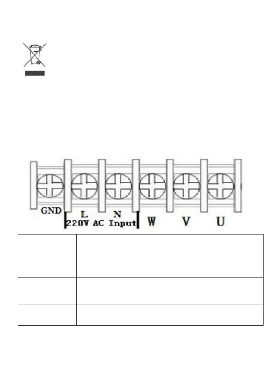
1.Instalaciónycableado1.
Descripcióndefuncionesyterminalesdelcircuito
principal(1)Demonofásicoatrifásico
4
L,N
Elterminaldesalidaseconectaalaredtrifásica.
TerminaldeentradamonofásicaCA220V
Motorde220VCA
etiqueta
Descripcióndelafunción
Terminal
EsteproductoestásujetoalasdisposicionesdelaDirectivaEuropea2012/19/CE.El
símboloquemuestrauncontenedordebasuratachadoindicaqueelproducto
requiereunarecogidaselectivaderesiduosenlaUniónEuropea.Estoseaplicaal
productoyatodoslosaccesoriosmarcadosconestesímbolo.Losproductos
marcadoscomotalesnopuedendesecharseconlosresiduosdomésticosnormales,sinoquedeben
llevarseaunpuntoderecogidaparareciclardispositivoseléctricosyelectrónicos.
U,V,W
Tierra
Terminaldepuestaatierra
Eliminacióncorrecta
Machine Translated by Google

TC
GNDcomún
PuertocortoX5yCOM,señaldeentrada
descripción
X2
Interruptordecontrolderotación)
Salidadepotenciade5V
FRENTEA
aporte
15V
X5
Puertodeentrada6
5V
Puertodecomunicación485+/485485
Puertodeentrada2(sección
velocidad2)
X3
Puertodeentrada5(Inverso)
250VCA5A/30VCC3A
CON
Señaldecorrienteexterna
eficaz
Instrucciones
tuberculosis
Salidadecolectorabierto1
SalidadereléA
Puertodeentrada3(sección
velocidad3)
X1
ALLÁ
eficaz
eficaz
SP1
(Interruptordeinversión)
eficaz
Normalabierto
aporte
PuertocortoX4yCOM,señaldeentrada
Puerto
SalidadereléB
eficaz
Interruptordecontrolderotación)
Funcional
X6
PuertocortoX3yCOM,señaldeentrada
PuertocortoX6yCOM,señaldeentrada
Entradadevoltajeanalógicode05/10V
eficaz
Salidadepotenciade15V
Voltajeanalógicoexterno
Entradadecorrientede420mA
PuertocortoX2yCOM,señaldeentrada
SalidadereléC
PuertocortoX1yCOM,señaldeentrada
Puertodeentrada4(Adelante)
TAyTBNormalCerrado,TAyTC
VL1
X4
Salida200mA15V
Opcional,soloparamodeloespecial
Puertodeentrada1(sección
velocidad1)
Suministraunapotenciadesalidade5Vy20mA.
2.Descripcióndelterminal
5
Machine Translated by Google

1
1
50
1
30
0
Frecuencia
Seccióndevelocidad7
45
1
0
1
Velocidaddesección1
Nota:
Sección
1
0
0
Sección
0
0
15
Secciónvelocidad4
Entradadevelocidad3
1 1
entradadevelocidad1
desconectar.
Seccióndevelocidad6
0
1
0
25
Velocidadprincipal
0
200
1
Secciónvelocidad2
Secciónvelocidad3
40
0
Sección
Entradadevelocidad2
1
35
0significaqueelpuertodeentradaseconectaconCOM,1significa
Secciónvelocidad5
1
0
Original
3.Tabladecontroldefrecuenciadeentradademúltiplesvelocidades:
6
Machine Translated by Google
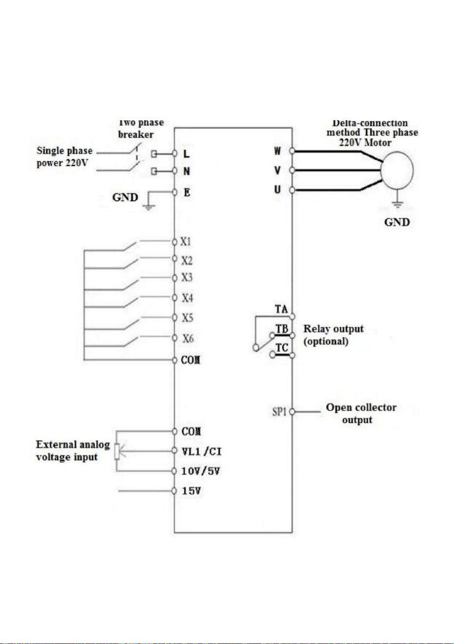
(1)Entradamonofásicasalidatrifásica
(Trifásico220V,sielmétododeconexiónenestrellade380Vnecesitacambiarseal
métododeconexiónentriángulode220V)
4.Diagramadecableadodefuncionamientobásico
7
Machine Translated by Google

8
5.Paneldeoperaciones
Machine Translated by Google

TeclaparavisualizarlainformacióndelInversor,como
Parámetro
Comenzar
Tecladecambiodeavance/retroceso
)
3
Iniciarsalidadelinversor
1
corriente,temperatura;
Elvalornuméricoserá
(
Detener/Reiniciar
Descripcióndelafunción
Presionebrevementeestateclayluego
disminucióndevalor
númerooparámetro
ParaseleccionarelmodoomododeProgramación(es
cambiarrápidamente
2
5
Losparámetrosmodificadosnosepuedenguardar.
Presioneestateclaparamodificarparámetros.
(
aumentodevalor
Cambiarenmododeprogramación,trotarenmodonormal
7
Presioneestatecla,luegola
comofrecuenciaobjetivo,frecuenciadesaliday
Icono
Llave
Avería,restablecimientodefallas
Parámetro
)
númerooparámetro
(Programación)
Porfavor,modifiquelosparámetrosenelestadodeparada,delocontrarioel
Nota
(Función/Guardar)
4
Cambio
disponiblesinimportarsielinversorestáenestrellaoparada),
Elvalornuméricoserá
Llave
6
Tecladeconfiguracióndedatosdefunción.Modonormal:presioneestatecla
cambiargradualmente.largo
8
6.Instruccionesdelasteclas:
9
Machine Translated by Google

freno.
2:Paradadefreno;
Hz
25
110/190V
Parámetro
Voltajefrenado
1
0400.0
especificación
Máximofuncionamiento
1
Analógicoexterno
0
P02
P05
0220.0/380.0
V
P11
V
065535
220/380V
0220.0/380.0
Unidad
detener;
Hz
1:Panel
65.0
P04
P01
potenciómetro;2:
Tiempodefrenado
1:desaceleración
Frecuenciamínima
fuentedecontrol
Introducircontraseña
Tensiónintermedia
065535
Modosdeparada
0140.0
1:RS485;
Hz
P08
0400.0
S
P14
0:Paradainercial;
Voltajemínimo
Pordefecto
0400.0
P12
P10
0
P03
P00
Iniciar/detener
Ocultarcontraseña
0400.0
Frecuenciadereferencia
20
Hz
02,5
0:Tecladodelpanel;
P07
0220.0/380.0
0
Intermedio
Parámetro
0
P13
frecuencia
P09
Mínimodefuncionamiento
0400.0
Voltajemáximo
2:Puertoexterno.
3:Emergencia
Frecuenciadetrabajo
señal4:RS485.
00000
P06
Rangodeparámetros
0,5
fuente
0
0:Tecladodelpanel;
50
Hz
10
1.Especificacióndeparámetros
7.Especificacióndeparámetros
Machine Translated by Google

11
P36
Hz
P44
Hz/S
Ajustedevelocidaddesección2
25
P23
Velocidaddedescenso
principal1.ªvelocidadde
descenso2.ªvelocidadde
descenso3.ªvelocidadde
descenso4.ªvelocidadde
descenso5.ªvelocidadde
descenso6.ªvelocidaddedescenso
0,160,0
25
P30
0400.0
Hz
11000
P17
50
P37
11000
Hz/S
Ajustedevelocidaddesección3
Hz/S
20
Revoluciónpara50Hz
0400.0
25
25
3
Hz
P18
P38
80
11000
11000
Hz/S
180
P45
Ajustedevelocidaddesección4
Configuracióndeloperador
0400.0
25
25
S
P31
11000
P39
11000
50
2800
Hz/S
08000
P46
15
Hz/S
0400.0
25
tiempodeamortiguación
P32
25
11000
Hz
P20
Hz/S
45
10120
P47
25
Hz/S
Tamañodelpasodeajuste
defrecuencia
Ajustedevelocidaddesección5
P26
11000
Hz
Hz
P33
Númerodemáquina
P40
11000
P48
1100
40
25
Hz/S
Proteccióncontrasobrecarga
Ajustedevelocidaddesección6
0400.0
25
11000
Hz
1255
Hz/S
P34
P41
11000
Hz/S
5
25
P21
0,1Hz
Ajustedevelocidaddesección7
25
0400.0
P27
0100.0
P35
P42
Hz/S
11000
Hz/S
Llegadaoperativa
Frecuenciadetrabajo
35
P24
Velocidadascendente
principal1.ªvelocidad
ascendente2.ªvelocidad
ascendente3.ªvelocidad
ascendente4.ªvelocidad
ascendente5.ªvelocidad
ascendente6.ªvelocidad
ascendente7.ªvelocidadascendente
25
P28
0400.0
11000
Hz
11000
Hz/S
Hz/S
P43
Seleccióndeprotección
contrasobretemperatura
Ajustedevelocidaddesección1
30
25
P22
25
P29
0400.0
11000
Hz
1
Machine Translated by Google

12
detener;
11:Teclahaciaadelante
P52
11000
15:velocidaddesección
2:paradadetecla;
7:reserva
Entradamultifunción6
Entradamultifunción2
15
0:noválido,laterminales
17:Trotarhaciaadelante;
cambiar;
Hz/S
operación;
1:topedecontroldecable
19:Emergencia
traspuesta;
P55
14
(PostedeenlaceX1)
entrada2;
señal.
25
9:inversióndecables
13:velocidaddelasección
5:cablehaciaadelante
Entradamultifunción5
14:velocidaddesección
nofuncional
6:cableinverso
12:interruptordemarchaatrás
P54
Entradamultifunción1
16:errorexterno
señal;
4:detenerlapulsación;
P50
P51
6
Entradamultifunción4
P53
7mavelocidaddedescenso
traspuesta;
codificación;
entrada1;
operación
entrada3;
8:errorderestablecimiento
3:operacióndecodificación;
9
5
Entradamultifunción3
10:Teclahaciaadelante
13
P49
18:Joginverso;
Machine Translated by Google

13
0
instrucciones
2:revolución3:
P50P55=20;
P62
Opcionesdeencendido
P67
Coeficientedevoltaje
adelante;
0:configuración
4:temperatura;5:
065535
28500
P69
20:Controlderelé.0:
noválido,no
0
220,0400/680
frecuencia;
instrucciones;
6:Para
tiempo;
1:reportarerrorcon
3:Encender
(SP1)
Entradamultifunción2
P66
Opcionesdevisualización
2:Encendido
P68
065535
60
60/180V
400/600V
2:establecerllegada
Idem(salidaderelé)
0
P65
Tiempodeestabilizacióndeentrada
EM
3:indicacióndefalla;
producción;
frecuencia;
P58
P60
actual;
0
contrarrestar.
Ajustedesubtensión
0220/380
Ajustedesobretensión
5:Paradadeemergencia;
1:operando
1:enfuncionamiento
0:encendidonormal;
Entradamultifunción1
señaldeinicio;
Machine Translated by Google

14
P88
P85
065535
065535
0
cantidad;
50
0400.0
20000mA
P80
Compensacióndepar
P74
Hz/S
P87
Cuartasobrecargadecorriente065535
Restablecimientodeparámetros
0300.0
cosaanáloga
0
20
20000mA
P84
065535
V
31440
Voltaje
50
20000mA
Primerasobrecargadecorriente
P76
P77
Mínimoexterno
menosvoltajedeentrada
065535
Velocidaddedescensodeltrote
sobrecarga
P79
20000mA
P83
10
P75
Hz/S
P86
Frecuenciadeavancelento
Sextasobrecargadecorriente
065535
Coeficientedecorriente
P70
11000
Jogaumentandolavelocidad
Séptimacorriente
P78
Compensacióndepar
065535
Hz
20000mA
Tercerasobrecargadecorriente
42000
cosaanáloga
P71despuésdeP71
20000mA
P82
2096
P71
11000
0100
compensación
P89
065535
valordecompensación
Opciones
Máximoexterno
1:MultiplicaP72por
065535
54321)
Jogdefrecuenciainversa
0
P73
P81
065535
configuración
065535
Hz
065535
Segundasobrecargadecorriente065535
Quintasobrecargadecorriente
(Eselreiniciocuando
Corrientecero
Compensacióndepar
0400.0
20000mA
20
20000mA
1130
P72
0:P72es
Sobrecargadecorrienteprincipal
Machine Translated by Google

P08eslacontraseñaoculta,siempremuestrasolo00000,nolareal
3.Presionelateclafunción/guardarparaingresaralparámetro;
1.Presionelatecladeprogramaciónparaingresaralestadodeprogramación;
valor.
menos1cuandoelinversorfuncionaduranteunahora.Elconvertidordefrecuencia
sedetendrácuandolacuentaregresivadeP127lleguea0horas.
6.Pulselatecladeprogramaciónparasalirdelestadodeprogramación.
CuandoP127=65535,lafuncióndecuentaregresivanoseinicia.
4.Utilicelasteclasdeflechaylateclashiftparamodificarelvalordelparámetro;
5.Pulselatecladefunción/guardarparaalmacenarelparámetro;
CuandoP127<65535,seiniciarálafuncióndecuentaregresiva,elP127
CuandoseingresaelvalordeP09=elvalorocultodeP08,semuestraP08
valoroculto,ysepuedencambiarelP08yotrosparámetros.ElP09
2.UtilicelasteclasdeflechaylateclaShiftparaencontrarlosparámetrosquenecesita.
modificado;
seanularáaldesconectarelcabledealimentaciónparareiniciar.
8.Procedimientodeconfiguracióndeparámetros:
Capítulo4Códigodefalla
2.Contraseñadeconfiguracióndeparámetrosyparadadeltiempodeinactividad:
0:Paradaporinercia;
=0Ventiladorenfuncionamiento
3:Emergencia
065535
Temperaturadearranquedelventilador
P127
2:Paradadefrenado;
ArranquedelVFD
0
Modosdeparadadejog
Tiempodefrenadodeljog
65535
P90
P91
Horasrestantes
freno.
S
1
0,1
yo
P124
cuando
1:Paradadesacelerada;
02,5
15
Machine Translated by Google

Hechoenchina
Proteccióndelmódulo
Fallasenelcircuitodeconducción
Visualizacióndelcódigodefalla
Entradaalarranquecuandoestáelectrificado
Error3
Error8
Descripcióndelcódigodefalla
Proteccióncontrasobrecorriente
Proteccióncontrasubtensión
Error6
Temperaturasexcesivasparaelradiador
Error9
Error7
Proteccióncontrasobretensión
Error1
Error4
Error2
Error5
Coneltiempo
Cortocircuito/Sobrecargadecorriente/Energía
Fallaexterna
16
Machine Translated by Google


Falownik
Nadal staramy się oferować Państwu narzędzia w konkurencyjnych cenach.
„Oszczędź połowę”, „Połowa ceny” lub inne podobne wyrażenia używane przez nas stanowią
jedynie szacunkowe oszczędności, jakie możesz uzyskać, kupując u nas określone narzędzia w
porównaniu z głównymi markami i niekoniecznie oznaczają one objęcie wszystkich kategorii narzędzi
oferowanych przez nas. Uprzejmie przypominamy, aby dokładnie sprawdzić, czy składając u nas
zamówienie faktycznie oszczędzasz połowę w porównaniu z głównymi markami.
MODEL:AT1-4000X
Wsparcie techniczne i certyfikat gwarancji elektronicznej www.vevor.com/support
- 1 -
Machine Translated by Google

POTRZEBUJESZ POMOCY? SKONTAKTUJ SIĘ Z NAMI!
- 1 -
Masz pytania dotyczące produktu? Potrzebujesz wsparcia technicznego? Skontaktuj się z
nami: Wsparcie
techniczne i certyfikat E-Gwarancji www.vevor.com/support
MODEL:AT1-4000X
To jest oryginalna instrukcja, przed użyciem należy uważnie przeczytać wszystkie
instrukcje. VEVOR zastrzega sobie jasną interpretację naszej instrukcji obsługi. Wygląd produktu
będzie zależał od produktu, który otrzymałeś. Prosimy o wybaczenie, że nie poinformujemy
Cię ponownie, jeśli w naszym produkcie pojawią się jakiekolwiek aktualizacje technologiczne lub
oprogramowania.
Falownik
Machine Translated by Google

4. Nie należy łączyć równolegle dwóch lub więcej transformatorów.
sprzęt .
OSTRZEŻENIE:
3. Nie zanurzaj falownika.
2. NIE ROZMONTOWYWAĆ.
i/lub poważne obrażenia.
odpowiedzialny za zgodność może unieważnić uprawnienia użytkownika do korzystania z usługi
Zmiany lub modyfikacje tej jednostki, które nie zostały wyraźnie zatwierdzone przez stronę
pożar i porażenie prądem.
poniższe instrukcje mogą spowodować porażenie prądem, pożar
1. Niedostosowanie się do tej instrukcji może spowodować awarię elektryczną,
specyfikacje dostarczone z tym falownikiem. Nieprzestrzeganie wszystkich
OSTRZEŻENIE:
Przeczytaj wszystkie ostrzeżenia dotyczące bezpieczeństwa, instrukcje, ilustracje i
OSTRZEŻENIE: RYZYKO PORAŻENIA PRĄDEM ELEKTRYCZNYM I POŻARU!
elektryka zgodnie ze wszystkimi obowiązującymi normami elektrycznymi.
7. Instalację tego falownika i związanego z nim okablowania musi wykonać wykwalifikowany
odsprzedawca do obsługi.
awarii, jeśli zewnętrzny przełącznik nie uruchomi ponownie urządzenia, skontaktuj się z
6. Nie używaj przedłużacza
5. Podłącz zasilacz bezpośrednio do gniazdka GFCI w miejscu narażonym na wilgoć.
rozmontuj ten sprzęt w dowolnym momencie, aby uniknąć niebezpieczeństwa. Po urządzeniu
To urządzenie jest urządzeniem wysokiego napięcia, nie należy podejmować prób jego podłączania.
ZAPISZ TE INSTRUKCJE
WAŻNE ZABEZPIECZENIA
- 2 -
Machine Translated by Google

w instalacji mieszkaniowej.
następujące środki
ostrożności. Zmień orientację lub położenie anteny
odbiorczej. Zwiększ odległość między produktem a odbiornikiem. Podłącz
produkt do gniazdka w innym obwodzie niż ten, do którego jest podłączony.
następujące dwa warunki:
są zaprojektowane tak, aby zapewnić rozsądną ochronę przed szkodliwymi zakłóceniami
Odbiornik jest podłączony.
urządzenie cyfrowe klasy B zgodnie z częścią 15 przepisów FCC. Niniejsze ograniczenia
To urządzenie jest zgodne z częścią 15 przepisów FCC. Eksploatacja podlega
Użytkownik jest zachęcany do podjęcia próby skorygowania zakłóceń za pomocą jednego lub więcej z następujących sposobów:
odbiór, który można ustalić poprzez wyłączenie i włączenie produktu,
sprzęt!
Uwaga: Ten produkt został przetestowany i uznany za zgodny z limitami
upoważnienie do obsługi produktu.
odpowiedzialny za zgodność może unieważnić prawo użytkownika do korzystania z urządzenia
produkt powoduje szkodliwe zakłócenia w odbiorze sygnału radiowego lub telewizyjnego
UWAGA: Zmiany lub modyfikacje, na które strona nie wyraziła wyraźnej zgody
zatwierdzone przez stronę odpowiedzialną za zgodność może unieważnić prawa użytkownika
gwarantuje, że w konkretnej instalacji nie wystąpią żadne zakłócenia. Jeśli to
szkodliwe zakłócenia w komunikacji radiowej. Nie ma jednak
OSTRZEŻENIE: Zmiany lub modyfikacje tego produktu nie są wyraźnie zabronione.
pomoc.
zakłócenia mogące powodować niepożądane działanie.
jeśli nie zostanie zainstalowany i użyty zgodnie z instrukcją, może spowodować
Ten produkt generuje, wykorzystuje i może emitować energię o częstotliwości radiowej,
2) Produkt ten musi akceptować wszelkie odbierane zakłócenia, w tym:
W celu uzyskania informacji skontaktuj się ze sprzedawcą lub doświadczonym technikiem radiowo-telewizyjnym.
1) Produkt ten może powodować szkodliwe zakłócenia.
Informacje FCC
- 3 -
Machine Translated by Google

1. Instalacja i okablowanie 1.
Opis zacisku obwodu głównego i funkcji (1)
Jednofazowy do trójfazowego
- 4 -
Jednofazowy zacisk wejściowy prądu przemiennego 220 V
Opis funkcji
Zacisk wyjściowy podłącza się do fazy trójfazowej
GND
etykieta
L, N
Terminal
Ten produkt podlega postanowieniom Dyrektywy Europejskiej 2012/19/
WE. Symbol przedstawiający przekreślony kosz na śmieci na kółkach
oznacza, że produkt wymaga oddzielnej zbiórki odpadów w Unii
Europejskiej. Dotyczy to produktu i wszystkich akcesoriów oznaczonych
tym symbolem. Produktów oznaczonych w ten sposób nie można wyrzucać razem ze
zwykłymi odpadami domowymi, ale należy je oddać do punktu zbiórki w celu recyklingu
urządzeń elektrycznych i elektronicznych.
Silnik prądu przemiennego 220 V
Zacisk uziemiający
U, W, W
Prawidłowa utylizacja
Machine Translated by Google

- 5 -
2. Opis terminala
skuteczny
SP1
TAM
skuteczny
Wyjście przekaźnikowe A
Port wejściowy 3 (sekcja -
prędkość 3)
X1
Wyjście kolektora otwartego 1
Zewnętrzny sygnał prądowy
skuteczny
Instrukcje
TB
250VAC 5A/30VDC 3A
Z
X3
Port wejściowy 5 (odwrotny)
5V
Port komunikacyjny 485+/485- 485
Port wejściowy 2 (sekcja -
prędkość 2)
Port wejściowy 6
OKŁADZINA
wejście
15 V
X5
X2
Przełącznik sterujący obrotem)
Moc wyjściowa 5V
Krótki port X5 i COM, sygnał wejściowy
opis
TC
Wspólne GND
Opcjonalnie, tylko dla specjalnego modelu
Port wejściowy 1 (sekcja -
prędkość 1)
zasilanie 5V 20mA wyjście mocy
VL1
X4
Wyjście 200mA15V
TA i TB Normalne zamknięcie, TA i TC
Wyjście przekaźnikowe C
Krótki port X1 i COM, sygnał wejściowy
Port wejściowy 4 (do przodu)
Prąd wejściowy 4-20mA
Krótki port X2 i COM, sygnał wejściowy
skuteczny
Moc wyjściowa 15 V
Zewnętrzne napięcie analogowe
Krótki port X3 i COM, sygnał wejściowy
Krótki port X6 i COM, sygnał wejściowy
X6
0-5/10 V Analogowe wejście napięciowe
Funkcjonalny
Wyjście przekaźnikowe B
skuteczny
Przełącznik sterujący obrotem)
wejście
Krótki port X4 i COM, sygnał wejściowy
Port
Normalnie otwarty
(Przełącznik cofania)
skuteczny
Machine Translated by Google

- 6 -
3. Tabela sterowania częstotliwością wejścia wielobiegowego:
1
40
00
Prędkość sekcji 3
Sekcja
wejście prędkości 2
1
35
0 oznacza, że port wejściowy łączy się z COM, 1 oznacza, że
Prędkość sekcji 5
1
0
Oryginalny
1
30
Prędkość sekcji 7
0
1
0
25
Prędkość główna
0
200
1
Prędkość sekcji 2
0
Sekcja
0
0
15
Prędkość sekcji 4
wejście prędkości 3
1 1
wejście prędkości 1
odłączyć.
Prędkość sekcji 6
1
1
50
0
Częstotliwość
Notatka :
45
1
0
1
Prędkość sekcji 1
Sekcja
Machine Translated by Google
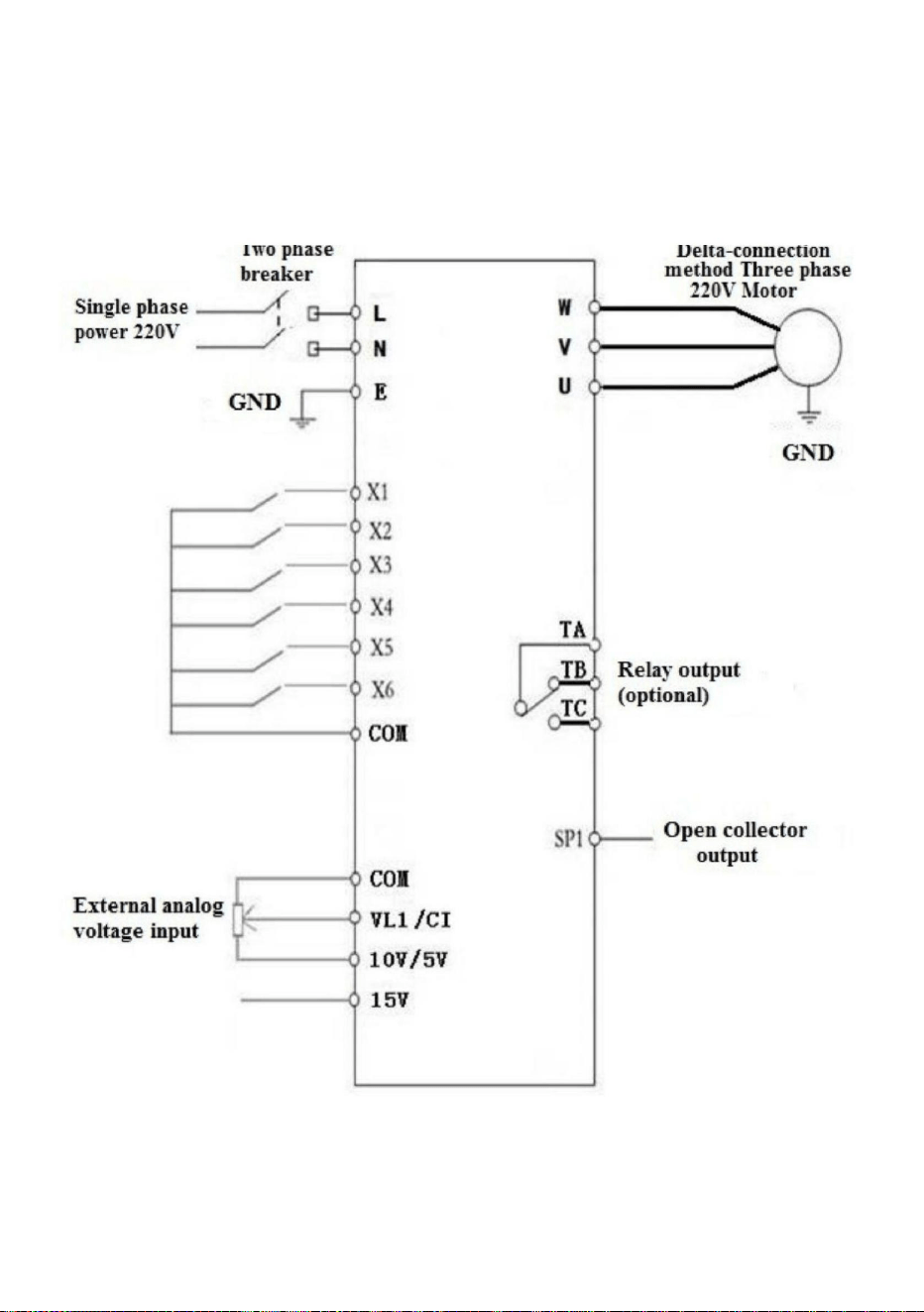
(1) Wejście jednofazowe, wyjście trójfazowe
(Trójfazowe 220 V, jeśli metoda połączenia w gwiazdę 380 V musi zostać zmieniona
na metodę połączenia w trójkąt 220 V)
4. Podstawowy schemat okablowania operacyjnego
- 7 -
Machine Translated by Google

- 8 -
5. Panel operacyjny
Machine Translated by Google
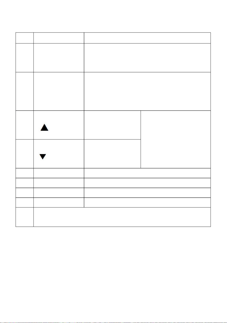
Naciśnij krótko ten klawisz, a następnie
(Funkcja/Zapisz)
spadek wartości
4
Notatka
Zmiana
wartość liczbowa będzie
dostępne bez względu na to, czy falownik jest w gwiazdę czy w stop),
Klawisz
6
Klawisz ustawiania danych funkcji. Tryb normalny: naciśnij ten
zmieniać się stopniowo. Długi
8
Klawisz przełączania przód/tył
)
naciśnij ten klawisz, a następnie
jako częstotliwość docelowa, częstotliwość wyjściowa i
Ikona
Klawisz
Awaria, resetowanie usterek
Parametr
)
liczba lub parametr
(Programowanie)
Proszę zmodyfikować parametry w stanie zatrzymania, w przeciwnym razie
liczba lub parametr
Do wyboru trybu lub trybu programowania (jest to
szybko się zmieniać
2
5
zmienionych parametrów nie można zapisać.
naciśnij ten klawisz, aby zmodyfikować parametry.
(
wzrost wartości
Zmiana w trybie programowania, bieganie w trybie normalnym
7
klawisz do wyświetlania informacji o falowniku, takich jak
Parametr
Start
3
Uruchom wyjście falownika
1
prąd, temperatura;
wartość liczbowa będzie
(
Zatrzymaj / Zresetuj
Opis funkcji
6. Instrukcje dotyczące klawiszy:
- 9 -
Machine Translated by Google

0---400,0
Minimalne napięcie
S
0---140,0
1:RS485;
Hz
P08
Tryby zatrzymywania
źródło sterowania
Wprowadź hasło
Napięcie pośrednie
0---65535
Czas hamowania
1: Zwalnianie
Minimalna częstotliwość
65,0
P04
P01
potencjometr;2:
zatrzymywać się;
Hz
1: Panel
0---220,0/380,0
Jednostka
P11
V
0---65535
220/380 V
0---220,0/380,0
V
Zewnętrzny analogowy
0
P02
P05
1
0---400,0
specyfikacja
Maksymalna praca
Napięcie hamowane
1
110/190 V
Parametr
2: Hamulec postojowy;
Hz
25
hamulec.
0
0: Klawiatura panelowa;
50
Hz
0,5
źródło
sygnał4: RS485.
00000
P06
Zakres parametrów
3:Awaryjny
Częstotliwość pracy
Minimalne działanie
0---400,0
Maksymalne napięcie
P13
częstotliwość
P09
Mediator
Parametr
0
2: Port zewnętrzny.
0---2,5
0: Klawiatura panelowa;
P07
0---220,0/380,0
Hz
0
Ukryj hasło
0---400,0
Częstotliwość odniesienia
Uruchom/zatrzymaj
0
P03
P00
20
P12
P10
Domyślny
0---400,0
P14
0: Zatrzymanie bezwładnościowe;
- 10 -
1. Specyfikacja parametrów
7. Specyfikacja parametrów
Machine Translated by Google

- 11 -
S
25
1---1000
P31
Prędkość sekcji 4 ustawienia
Ustawienia nośnika
25
0---400,0
P46
0-8000
Hz/sekundę
15
1---1000
P39
2800
Hz/sekundę
50
1---1000
25
P32
P20
Hz
25
0---400,0
czas buforowy
Hz/sekundę
25
Prędkość sekcji 5 ustawień
Wielkość kroku regulacji
częstotliwości
10
45
Hz/sekundę
P47
1---20
P23
25
Główna prędkość zniżania
1. prędkość zniżania 2.
prędkość zniżania 3.
prędkość zniżania 4.
prędkość zniżania 5.
prędkość zniżania 6.
prędkość zniżania
0,1---60,0
P44
Hz
Hz/sekundę
25
Ustawienie prędkości sekcji 2
P37
50
Hz/sekundę
1---1000
0---400,0
P30
P17
1---1000
25
Hz
0---400,0
3
25
20
Hz/sekundę
Ustawienie prędkości sekcji 3
Rewolucja dla 50Hz
Hz/sekundę
1---1000
P45
1---80
P18
Hz
1---1000
P38
80
Przyjazd operacyjny
Hz/sekundę
35
Częstotliwość pracy
P35
0---100,0
1---1000
Hz/sekundę
P42
0---400,0
P28
Hz
1---1000
Główna prędkość
narastająca 1. prędkość
narastająca 2. prędkość
narastająca 3. prędkość
narastająca 4. prędkość
narastająca 5. prędkość
narastająca 6. prędkość
narastająca 7. prędkość narastająca
P24
25
30
Ustawienie prędkości sekcji 1
P22
25
Hz/sekundę
1---1000
P43
Wybór zabezpieczenia
przed przegrzaniem
Hz/sekundę
Hz
1---1000
P36
1
25
0---400,0
P29
P33
Numer maszyny
Hz
1---1000
P40
P26
Hz
1---1000
Prędkość sekcji 6 ustawień
Zabezpieczenie przed przeciążeniem
25
0---400,0
40
P48
1---100
Hz/sekundę
25
1---1000
P41
5
Hz/sekundę
Hz
1---1000
P34
1-255
Hz/sekundę
25
0---400,0
P27
P21
25
Prędkość sekcji 7 ustawień
0,1 Hz
Machine Translated by Google

- 12 -
Wielofunkcyjne wejście 5
14:sekcja prędkości
13: prędkość sekcji
5:przewód do przodu
sygnał.
25
9: odwrócenie przewodu
wejście 2;
P55
14
(X1 zacisk zaciskowy)
19: Awaryjny
przełączanie;
działanie;
1: zatrzymanie sterowania przewodowego
17: Trucht do przodu;
przełącznik;
Hz/sekundę
0:nieprawidłowy,terminal jest
Wielofunkcyjne wejście 6
Wielofunkcyjne wejście 2
15
7: rezerwacja
2: zatrzymanie klawisza;
15: prędkość sekcji
P52
1---1000
zatrzymywać się;
11:przewijanie do przodu
P49
10:przewijanie do przodu
13
18: Bieg wsteczny;
9
5
Wielofunkcyjne wejście 3
wejście 3;
8: resetowanie błędu
3:operacja kluczowania;
wejście 1;
działanie
P53
7. prędkość zniżania
przełączanie;
6
Wielofunkcyjne wejście 4
P51
klawiszowanie;
P50
16: błąd zewnętrzny
sygnał;
4: zatrzymaj wpisywanie;
12: przełącznik cofania
P54
Wielofunkcyjne wejście 1
niedziałający
6: odwrócenie przewodu
Machine Translated by Google

- 13 -
3: sygnalizacja usterki;
częstotliwość;
czas;
3: Włącz zasilanie
0---65535
400/600 V
częstotliwość;
instrukcje;
6: Dla
1: zgłoś błąd z
P66 60
(SP1)
Wielofunkcyjne wejście 2
P68
Opcje wyświetlania
2: Włącz zasilanie
60/180 V
0
instrukcje
2: rewolucja 3:
Opcje włączania
Współczynnik napięcia
P69
20: Sterowanie przekaźnikiem.
0: nieprawidłowe, nie
0
do przodu;
0: ustawienie
4: temperatura; 5:
0---65535
220,0---400/680
5: Zatrzymanie awaryjne;
1:operacyjny
1: operacyjny
0: normalne włączenie;
odwracać.
0---220/380
Wielofunkcyjne wejście 1
sygnał startu;
P50---P55=20;
P62
P67 28500
2: ustaw przybycie
To samo (Wyjście przekaźnikowe)
0
P65
Czas stabilizacji wejścia
SM
aktualny;
P58
P60
0
Ustawienie zbyt niskiego napięcia
Ustawienie przepięcia
wyjście;
Machine Translated by Google

- 14 -
P70
P78
1---1000
Przesuń częstotliwość do przodu
Szóste przeciążenie prądowe
0-65535
Współczynnik prądu
Hz/sekundę
P86
20000 mA
P83
10
P75
Prędkość zejścia podczas joggingu
przeciążać
P79
P77
Minimalne zewnętrzne
minus napięcie wejściowe
0-65535
50
20000 mA
Pierwsze przeciążenie prądowe
P76
31440
woltaż
20000 mA
P84
0---65535
V
0
20
Czwarte przeciążenie prądowe 0-65535
Resetowanie parametrów
0---300,0
analog
Hz/sekundę
P87
P74
Kompensacja momentu obrotowego
P80
0---400,0
20000 mA
0
kwota;
P85
0-65535
0---65535
0:P72 jest
50
P88
20
20000 mA
1130
P72
Przeciążenie prądowe
0---400,0
20000 mA
Piąte przeciążenie prądowe
(To jest reset, kiedy
Prąd zerowy
Kompensacja momentu obrotowego
Hz
0-65535
Drugie przeciążenie prądowe 0-65535
P81
0---65535
ustawienie
Częstotliwość odwrotna Jog
0
P73
Maksymalny zewnętrzny
1: Pomnóż P72 przez
0---65535
0-65535
P89
0-65535
wartość odszkodowania
opcje
0---100
(54321)
odszkodowanie
P82
2096
P71
20000 mA
42000
analog
P71 po P71
1---1000
Hz
20000 mA
Trzecie przeciążenie prądowe
Kompensacja momentu obrotowego
0---65535
Prędkość wzrastająca podczas biegu
Siódmy prąd
Machine Translated by Google

5. Naciśnij przycisk funkcji/zapisz, aby zapisać parametr;
Gdy P127 < 65535, rozpocznie się funkcja odliczania, P127 będzie
Gdy P127=65535, funkcja odliczania nie zostanie uruchomiona.
4. Użyj klawiszy strzałek i klawisza Shift, aby zmienić wartość parametru;
zostanie anulowane po odłączeniu kabla zasilającego w celu ponownego uruchomienia.
3. Naciśnij przycisk funkcji/zapisz, aby wejść do parametru;
zmodyfikowany;
ukryta wartość, a P08 i inne parametry mogą być zmienione. P09
Po wprowadzeniu wartości P09 = ukrytej wartości P08, wyświetla się P08
2. Użyj klawiszy strzałek i klawisza Shift, aby znaleźć parametry, które należy
1. Naciśnij przycisk programowania, aby wejść w tryb programowania;
wartość.
P08 to ukryte hasło, które zawsze pokazuje tylko 00000, a nie rzeczywiste
zostanie zatrzymane, gdy odliczanie P127 osiągnie 0 godzin.
minus 1, gdy falownik pracuje przez godzinę. Konwerter częstotliwości będzie
6. Naciśnij przycisk programowania, aby wyjść ze stanu programowania.
8. Procedura ustawiania parametrów:
Rozdział 4 Kod błędu
2. Hasło do ustawiania parametrów i zatrzymania przestoju:
1
0,1
65535
Tryby zatrzymywania Jog
P91
Czas hamowania biegowego
Pozostałe godziny
P90
3:Awaryjny
0---65535
P127 H
2: Hamowanie;
VFD zaczyna
0
1: Zwalnianie zatrzymania;
Kiedy
P124
Temperatura startu wentylatora
0: Zatrzymanie bezwładnościowe;
=0 Wentylator pracuje
0---2,5
℃
hamulec.
S
- 15 -
Machine Translated by Google

Wyprodukowano w Chinach
Zabezpieczenie podnapięciowe
Błąd 6
Błąd 2
Błąd 4
Błąd 5
Błąd 1
Ochrona modułu
Błąd 3
Zwarcie/Przeciążenie prądowe/Moc
Nadgodziny
Błąd zewnętrzny
Opis kodu błędu
Zabezpieczenie nadprądowe
Nadmierne temperatury dla chłodnicy
Błąd 9
Wyświetlanie kodu błędu
Wejście przy uruchomieniu po podłączeniu do prądu
Awarie obwodów napędowych
Błąd 8
Zabezpieczenie przed przepięciem
Błąd 7
- 16 -
Machine Translated by Google


MODEL:AT1-4000X
Wij streven er voortdurend naar om u gereedschappen tegen concurrerende prijzen te leveren.
"Save Half", "Half Price" of andere soortgelijke uitdrukkingen die wij gebruiken, geven alleen een schatting weer
van de besparingen die u kunt behalen door bepaalde gereedschappen bij ons te kopen in vergelijking met de grote
topmerken en betekent niet noodzakelijkerwijs dat alle categorieën gereedschappen die wij aanbieden, worden gedekt.
Wij herinneren u eraan om zorgvuldig te controleren of u daadwerkelijk de helft bespaart in vergelijking met de
grote topmerken wanneer u een bestelling bij ons plaatst.
Omvormer
Technische ondersteuning en e-garantiecertificaat www.vevor.com/support
- 1 -
Machine Translated by Google

HULP NODIG? NEEM CONTACT MET ONS OP!
- 1 -
Dit is de originele instructie, lees alle handleidingen zorgvuldig door voordat u het
product gebruikt. VEVOR behoudt zich een duidelijke interpretatie van onze gebruikershandleiding
voor. Het uiterlijk van het product is afhankelijk van het product dat u hebt ontvangen.
Vergeef ons dat we u niet opnieuw zullen informeren als er technologie- of software-updates
voor ons product zijn.
MODEL:AT1-4000X
Heeft u vragen over het product? Heeft u technische ondersteuning nodig? Neem dan gerust
contact met
ons op: Technische ondersteuning en E-garantiecertificaat
www.vevor.com/support
Omvormer
Machine Translated by Google

WAARSCHUWING: GEVAAR VOOR ELEKTRISCHE SCHOKKEN EN BRAND!
Lees alle veiligheidswaarschuwingen, instructies, illustraties en
elektricien die voldoet aan alle toepasselijke elektrische voorschriften.
7. De installatie van deze omvormer en de bijbehorende bedrading moet worden uitgevoerd door gekwalificeerde vakmensen.
wederverkoper voor afhandeling.
Als de externe schakelaar het apparaat niet opnieuw kan opstarten, neem dan contact op met uw
6. Gebruik geen verlengsnoer
5. Sluit de voeding rechtstreeks aan op een stopcontact met aardlekschakelaar voor vochtige ruimtes.
demonteer deze apparatuur op elk gewenst moment om gevaar te voorkomen. Nadat een apparaat
Dit apparaat is een apparaat met een hoog voltage. Probeer het niet te gebruiken.
4. Sluit niet twee of meer transformatoren parallel aan
apparatuur .
WAARSCHUWING:
3. Dompel de omvormer niet onder.
2. NIET DEMONTEREN.
en/of ernstig letsel.
verantwoordelijk voor naleving kan de bevoegdheid van de gebruiker om de
Wijzigingen of aanpassingen aan deze eenheid die niet uitdrukkelijk door de partij zijn goedgekeurd
De onderstaande instructies kunnen leiden tot een elektrische schok of brand.
brand en elektrocutie.
1. Het niet naleven van deze instructie kan leiden tot een elektrische storing,
specificaties die bij deze omvormer worden geleverd. Als u niet alle
WAARSCHUWING:
BEWAAR DEZE INSTRUCTIES
BELANGRIJKE VEILIGHEIDSMAATREGELEN
- 2 -
Machine Translated by Google

LET OP: Wijzigingen of aanpassingen die niet uitdrukkelijk door de partij zijn goedgekeurd
goedgekeurd door de partij die verantwoordelijk is voor naleving, kan de gebruikersrechten ongeldig verklaren
garanderen dat er geen interferentie zal optreden in een bepaalde installatie. Als dit
schadelijke interferentie van radiocommunicatie. Er is echter geen
WAARSCHUWING: Wijzigingen of aanpassingen aan dit product die niet uitdrukkelijk zijn
bijstand.
storingen die een ongewenste werking kunnen veroorzaken.
indien niet geïnstalleerd en gebruikt in overeenstemming met de instructies, kan dit leiden tot
Dit product genereert, gebruikt en kan radiofrequentie-energie uitstralen, en
2) Dit product moet alle ontvangen interferentie accepteren, inclusief
ÿ Raadpleeg de dealer of een ervaren radio-/tv-technicus voor
1) Dit product kan schadelijke interferentie veroorzaken.
in een residentiële installatie.
De ontvanger is aangesloten.
volgende maatregelen. ÿ
Heroriënteer of verplaats de ontvangstantenne. ÿ Vergroot
de afstand tussen het product en de ontvanger. ÿ Sluit het product aan op een
stopcontact op een ander circuit dan dat waarop het product is aangesloten.
de volgende twee voorwaarden:
zijn ontworpen om redelijke bescherming te bieden tegen schadelijke interferentie
een digitaal apparaat van klasse B volgens Deel 15 van de FCC-regels. Deze limieten
Dit apparaat voldoet aan Deel 15 van de FCC-regels. De werking is onderworpen aan
De gebruiker wordt aangemoedigd om te proberen de interferentie door een of meer van de
ontvangst, die kan worden bepaald door het product uit en aan te zetten, de
apparatuur!
Let op: Dit product is getest en voldoet aan de limieten voor
bevoegdheid om het product te bedienen.
verantwoordelijk voor naleving kan de bevoegdheid van de gebruiker om de
product veroorzaakt schadelijke interferentie met radio of televisie
FCC-informatie
- 3 -
Machine Translated by Google

1. Installatie en bedrading 1.
Hoofdcircuitaansluiting en functiebeschrijving
(1)Enkele fase tot driefase
Enkele fase AC 220V ingangsklem
Functiebeschrijving
Uitgangsklem aansluiten op driefase
Aardingsklem
label
L, N
Terminal
Dit product valt onder de bepalingen van de Europese richtlijn 2012/19/
EG. Het symbool met een doorgestreepte afvalbak geeft aan dat
het product in de Europese Unie gescheiden afvalinzameling vereist.
Dit geldt voor het product en alle accessoires die met dit symbool zijn
gemarkeerd. Producten die als zodanig zijn gemarkeerd, mogen niet met het
normale huishoudelijke afval worden weggegooid, maar moeten worden ingeleverd bij
een inzamelpunt voor recycling van elektrische en elektronische apparaten.
GND
U,V,W
220V AC-motor
Correcte verwijdering
- 4 -
Machine Translated by Google

Relaisuitgang B
Instructies
effectief
Extern stroomsignaal
Open-collector uitgang 1
TB
Ingangspoort 5 (omgekeerde
X3
MET
250VAC 5A/30VDC 3A
effectief
DAAR
effectief
Ingangspoort 3 (sectie-
snelheid 3)
X1
Relaisuitgang A
rotatie (bedieningsschakelaar)
X2
5V uitgangsvermogen
Gemeenschappelijke GND
TC
beschrijving
Korte poort X5 en COM, ingangssignaal
Invoerpoort6
Ingangspoort 2 (sectie-
snelheid 2)
485+/485- 485 communicatiepoort
5V
15V
invoer
X5
GEZICHT
Ingangspoort 4 (vooruit)
Korte poort X1 en COM, ingangssignaal
Relaisuitgang C
TA en TB Normaal Sluiten, TA en TC
15V uitgangsvermogen
effectief
Korte poort X2 en COM, ingangssignaal
Externe analoge spanning
4-20mA Stroomingang
Ingangspoort 1 (sectie-
snelheid 1)
Optioneel, alleen voor speciaal model
voeding 5V 20mA uitgangsvermogen
200mA15V-uitgang
X4
VL1
Normaal geopend
Haven
Korte poort X4 en COM, ingangssignaal
invoer
SP1
(Omkeerschakelaar)
effectief
Functioneel
Korte poort X6 en COM, ingangssignaal
Korte poort X3 en COM, ingangssignaal
X6
0-5/10 V analoge spanningsingang
rotatie (bedieningsschakelaar)
effectief
2. Terminalbeschrijving
- 5 -
Machine Translated by Google

0
0
1
snelheidsinvoer 3snelheidsingang 1
1
25
loskoppelen.
Sectie
0
0
0
Sectiesnelheid 6
15
Sectiesnelheid 4
1
45
0
Sectie
1
0
0
1
Frequentie
1
1
50
Sectiesnelheid 1
Opmerking :
Sectiesnelheid 5
1
30
Origineel
1
0
Sectiesnelheid 7
40
0
snelheidsingang 2
Sectie
1
35
0 betekent dat de invoerpoort is verbonden met COM, 1 betekent
0
Sectiesnelheid 3
0
1
20
Sectiesnelheid 2
Hoofdsnelheid
1
3. Tabel met frequentieregeling voor meerdere snelheden:
- 6 -
Machine Translated by Google
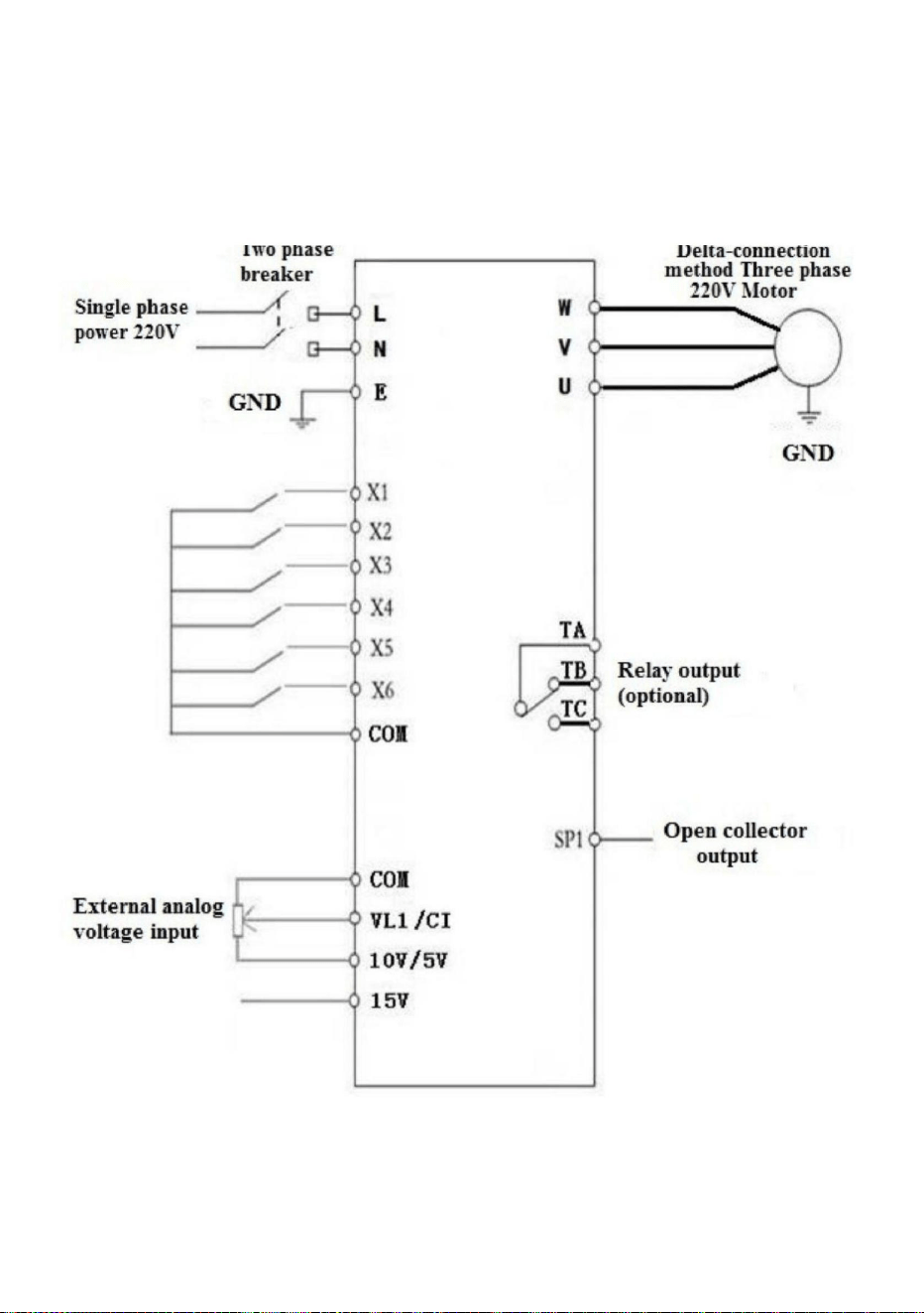
(Drie fasen 220V, indien 380V ster-aansluitmethode moet worden gewijzigd
naar de 220V driehoek-aansluitmethode)
(1) Eénfase-ingang, driefase-uitgang
4. Basisbedradingsschema voor de bediening
- 7 -
Machine Translated by Google

- 8 -
5. Bedieningspaneel
Machine Translated by Google

druk op deze toets, dan de
Icon
waardeverhoging
Druk op deze toets om parameters te wijzigen.
Schakelen in de programmeermodus, joggen in de normale modus
(
Sleutel
7
Voor het selecteren van de modus of de programmeermodus (het is
nummer of parameter
snel veranderen
2
5
Gewijzigde parameters kunnen niet worden opgeslagen.
stroom, temperatuur;
1
numerieke waarde zal
Functiebeschrijving
Druk kort op deze toets en vervolgens
waardevermindering
3
(
Start Inverter-uitgang
toets om de informatie van de omvormer weer te geven, zoals
Parameter
Begin
Stoppen / Resetten
Vooruit/achteruit Vooruit/achteruit schakelsleutel
)
8
Functiegegevens-instellingstoets. Normale modus: druk hierop
geleidelijk veranderen. Lang
(Functie/Opslaan)
4
beschikbaar, ongeacht de omvormer (ster of stop),
Verschuiving
de numerieke waarde zal
Sleutel
6
Parameter
Opmerking
nummer of parameter
(Programmeren)
)
Wijzig de parameters onder de stopstatus, anders wordt de
Storing, fout resetten
als doelfrequentie, uitgangsfrequentie en
6. Sleutelinstructies:
- 9 -
Machine Translated by Google

Wachtwoord verbergen
P01
P04
65.0
Minimale frequentie
potentiometer;2:
1: Vertraging
Remtijd
Eenheid
0---220.0/380.0
1: Paneel
Hertz
stop;
P08
Hertz
1:RS485;
0---140.0
S
0---400.0
Tussenspanning
0---65535
Voer wachtwoord in
controle bron
Stopstanden
1
Geremde spanning
specificatie
0---400.0
Maximale werkingssnelheid
25
Hertz
2: Remstop;
Parameter
110/190 V
V
0---220.0/380.0
220/380 V
0---65535
V
P11
1
P02
0
P05
Externe analoge
Maximale spanning
0---400.0
Minimale bedrijfskosten
Werkfrequentie
3:Noodgeval
Parameter
Tussenliggend
P09
0
frequentie
2:Externe poort.
50
0: Paneeltoetsenbord;
Hertz
0
rem.
P13
Parameterbereik
P06
00000
signaal4: RS485.
bron
0,5
P10
P12
P00
P03
0
Minimale spanning
0:Traagheidsstop;
P14
0---400.0
Standaard
Hertz
0---220.0/380.0
P07
0
0: Paneeltoetsenbord;
Starten/stoppen
0---2.5
20
Referentiefrequentie
0---400.0
- 10 -
1. Parameterspecificatie
7. Parameterspecificatie
Machine Translated by Google

- 11 -
P46
1-255
0-8000
Hz/S
15
1---1000
P39
Hz/S
2800
50
S
25
1---1000
P31
Dragerinstelling
Sectie snelheid 4 instelling
25
0---400.0
Hz/S
25
Sectie snelheid 5 instelling
Frequentie aanpassen
stapgrootte
10
45
Hz/S
P47
1---20
1---1000
25
P32
P20
Hertz
25
0---400.0
buffertijd
P37
50
Hz/S
1---1000
0---400.0
P30
P17
1---1000
Hertz
P23
25
0,1---60,0
Belangrijkste daalsnelheid
1e daalsnelheid 2e
daalsnelheid 3e
daalsnelheid 4e
daalsnelheid 5e
daalsnelheid 6e
daalsnelheid
P44
Hz/S
Hertz
25
Sectie snelheid 2 instelling
Hz/S
1---1000
P45
1---80
P18
Hertz
1---1000
80
P38
25
0---400.0
3
25
20
Hz/S
Sectie snelheid 3 instelling
Revolutie voor 50Hz
0---400.0
P28
Hertz
1---1000
Belangrijkste stijgende
snelheid 1e stijgende
snelheid 2e stijgende
snelheid 3e stijgende
snelheid 4e stijgende
snelheid 5e stijgende
snelheid 6e stijgende
snelheid 7e stijgende snelheid
P24
25
Aankomst operationeel
Hz/S
35
Werkfrequentie
P35
0---100.0
1---1000
Hz/S
P42
Hertz
1---1000
P36
1
25
0---400.0
P29
30
Sectie snelheid 1 instelling
P22
25
Hz/S
1---1000
Selectie
overtemperatuurbeveiliging
P43
Hz/S
Sectie snelheid 6 instelling
Overbelastingsbeveiliging
25
0---400.0
40
1---100
P48 Hz/S
25
Machinenummer
P33
Hertz
1---1000
P40
P26
Hertz
1---1000
0---400.0
25
P27
P21
25
Sectie snelheid 7 instelling
0,1 Hz
1---1000
P41
5
Hz/S
Hertz
1---1000
P34
Hz/S
Machine Translated by Google

- 12 -
16: externe fout
(X1-aansluitpost)
14
P55
invoer 2;
1: draadbesturingsstop
operatie;
schakelen;
19: Noodgeval
5: draad vooruit
13: sectiesnelheid
Multifunctionele ingang 5
25
signaal.
9: draad omkeren
2: toetsaanslag;
7: reservering
15: sectiesnelheid
11:vooruit toetsen
stop;
1---1000
P52
0:ongeldig,terminal is
Hz/S
schakelaar;
17: Vooruit joggen;
Multifunctionele ingang 2
15
Multifunctionele ingang 6
3: toetsbewerking;
8: fout resetten
invoer 3;
7e afdalingssnelheid
P53
schakelen;
operatie
invoer 1;
13
10:vooruit typen
18: Jog Achteruit;
P49
Multifunctionele ingang 3
5
9
Multifunctionele ingang 1
P54
12: achteruit schakelaar
14: sectiesnelheid
niet-functionerend
6: draad omgekeerd
P50
P51
Multifunctionele ingang 4
6
sleutelen;
4:Stop met typen;
signaal;
Machine Translated by Google

- 13 -
2: aankomst instellen
Idem (Relaisuitgang)
0
Weergaveopties
(SP1)
Multifunctionele ingang 2
2: Inschakelen
P68
instructies;
frequentie;
6: Voor
1: meld fout met
P66 60
tijd;
3: Inschakelen
0---65535
60/180 V
0: instelling
4: temperatuur; 5:
vooruit;
20: Relaisbesturing.
0: ongeldig, nee
0
0---65535
Spanningscoëfficiënt
P69
instructies
0
2: revolutie 3:
Opties voor inschakelen
220.0---400/680 400/600 V
P50 --- P55 = 20;
P62
startsignaal;
Multifunctionele ingang 1
P67 28500
achteruit.
0---220/380
1: in werking
5: Noodstop;
1: in werking
0: normale stroom aan;
3: storingsindicatie;
uitvoer;
frequentie;
Overspanningsinstelling
P58
huidig;
P60
0
Onderspanningsinstelling
P65
Invoerstabilisatietijd
mevrouw
Machine Translated by Google

P82
min ingangsspanning
Minimaal extern
P77
P79
0-65535
overbelasting
Jog-afdaalsnelheid
spanning
31440
P76
Eerste stroomoverbelasting
20000mA
50
Stroomcoëfficiënt
0-65535
Zesde stroomoverbelasting
Jog-voorwaartse frequentie
1---1000
P70
10
P83
P75
20000mA
P86
Hz/S
20000mA
0---400.0
Koppelcompensatie
P74
P80
0---65535
0-65535
P85
50
hoeveelheid;
0
20
0
V
0---65535
P84
20000mA
P87
Hz/S
0---300.0
analoog
Parameters resetten
Vierde stroomoverbelasting 0-65535
instelling
0---65535
P81
Tweede stroomoverbelasting 0-65535
0-65535
Hertz
1: Vermenigvuldig P72 met
Maximale externe
0---65535
P73
0
0-65535
P72
1130
Hoofdstroom overbelasting
20000mA
P88
Jog-omkeerfrequentie
20
0:P72 is
Koppelcompensatie
Nulstroom
(Het is de reset wanneer
Vijfde stroomoverbelasting
20000mA
0---400.0
Derde stroomoverbelasting
20000mA
Hertz
P71 na P71
analoog
42000
P78
Zevende stroming
Jog stijgende snelheid
Koppelcompensatie
0---65535
compensatie
0---100
opties
compensatiewaarde
54321)
0-65535
20000mA
P89
1---1000
P71
2096
- 14 -
Machine Translated by Google

2. Wachtwoord voor parameterinstelling en stop van downtime:
Hoofdstuk 4 Foutcode
8. Parameterinstellingsprocedure:
Wanneer de waarde van P09 wordt ingevoerd = de verborgen waarde van P08, wordt P08 weergegeven
2. Gebruik de pijltjestoetsen en de Shift-toets om de parameters te vinden die u wilt wijzigen.
1. Druk op de programmeertoets om naar de programmeerstatus te gaan;
waarde.
P08 is het verborgen wachtwoord, het toont altijd alleen 00000, niet het werkelijke
gestopt worden wanneer de aftelling van P127 tot 0 uur is.
min 1 wanneer de omvormer een uur draait. De frequentieomvormer zal
6. Druk op de programmeertoets om de programmeerstatus te verlaten.
5. Druk op de functie-/opslagtoets om de parameter op te slaan;
Wanneer P127 < 65535, start de aftelfunctie, de P127 zal
Wanneer P127=65535, start de aftelfunctie niet.
4. Gebruik de pijltjestoetsen en de Shift-toets om de parameterwaarde te wijzigen;
wordt geannuleerd wanneer u de stroomkabel loskoppelt om opnieuw op te starten.
3. Druk op de functie-/opslaantoets om de parameter te openen;
gewijzigd;
verborgen waarde, en de P08 en andere parameters kunnen worden gewijzigd. De P09
1: Vertragen stoppen;
wanneer
Ventilator starttemperatuur
P124
0:Inertiestop;
=0 Ventilator draait
0---2.5
ÿ
S
rem.
1
0.1
H
65535
Jog-stopmodi
Jog-remtijd
P91
P90
Resterende uren
P127
3:Noodgeval
0---65535
VFD start
2:Remmen stoppen;
0
- 15 -
Machine Translated by Google

- 16 -
Beschrijving van de foutcode
Overstroombeveiliging
Fout 9
Te hoge temperaturen voor radiator
Weergave van foutcodes
Input bij opstarten bij elektrische stroom
Storingen in het rijcircuit
Fout 8
Fout 7
Overspanningsbeveiliging
Onderspanningsbeveiliging
Fout 6
Fout 2
Fout 5
Fout 4
Fout 1
Modulebescherming
Fout 3
Overwerk
Kortsluiting/stroomoverbelasting/stroomuitval
Externe fout
Gemaakt in China
Machine Translated by Google


MODELL:AT1-4000X
Vi fortsätter att vara engagerade i att ge dig verktyg till konkurrenskraftiga priser.
"Spara hälften", "halva priset" eller andra liknande uttryck som används av oss representerar
bara en uppskattning av besparingar du kan dra nytta av att köpa vissa verktyg hos oss jämfört med
de stora toppmärkena och betyder inte nödvändigtvis att täcka alla kategorier av verktyg som erbjuds
av oss. Du påminns vänligen om att noggrant kontrollera när du gör en beställning hos oss om
du faktiskt sparar hälften i jämförelse med de främsta stora varumärkena.
Inverter
Teknisk support och e-garanticertifikat www.vevor.com/support
- 1 -
Machine Translated by Google

BEHÖVER HJÄLP? KONTAKTA OSS!
- 1 -
Har du produktfrågor? Behöver du teknisk support? Kontakta oss gärna: Teknisk support och
e-
garanticertifikat www.vevor.com/support
MODELL:AT1-4000X
Detta är den ursprungliga instruktionen, läs alla instruktioner noggrant innan du
använder den. VEVOR reserverar sig för en tydlig tolkning av vår användarmanual. Utseendet
på produkten är beroende av den produkt du fått. Ursäkta oss att vi inte kommer att
informera dig igen om det finns någon teknik eller mjukvaruuppdateringar på vår produkt.
Inverter
Machine Translated by Google

- 2 -
SPARA DESSA INSTRUKTIONER
VIKTIGA SÄKERHETSÅTGÄRDER
Läs alla säkerhetsvarningar, instruktioner, illustrationer och
VARNING: RISK FÖR ELEKTRISK STÖT OCH BRAND!
elektriker i enlighet med alla tillämpliga elföreskrifter.
7. Installation av denna växelriktare och tillhörande ledningar måste göras av en kvalificerad
återförsäljare för hantering.
Om den externa omkopplaren inte startar om enheten, kontakta din
6. Använd inte en förlängningssladd
5. Anslut strömförsörjningsenheten direkt till ett GFCI våtuttag.
demontera denna utrustning när som helst för att undvika fara. Efter en enhet
Denna utrustning är en högspänningsenhet, försök inte göra det
4. Anslut inte två eller flera transformatorer parallellt
utrustning .
VARNING:
3. Sänk inte växelriktaren i vatten.
2. MONTERA INTE .
och/eller allvarlig skada.
ansvarig för efterlevnad kan ogiltigförklara användarens behörighet att driva
Ändringar eller modifieringar av denna enhet som inte uttryckligen godkänts av parten
instruktionerna nedan kan leda till elektriska stötar, brand
brand och elstöt.
1. Underlåtenhet att följa denna instruktion kan resultera i ett elektriskt fel,
specifikationer som medföljer denna växelriktare. Misslyckas med att följa alla
VARNING:
Machine Translated by Google

- 3 -
FCC-information
VARNING: Ändringar eller modifieringar som inte uttryckligen godkänts av parten
godkänd av parten.ansvarig för efterlevnad kan ogiltigförklara användarens
garantera att störningar inte kommer att inträffa i en viss installation. Om detta
skadliga störningar på radiokommunikation. Det finns dock ingen
VARNING: Ändringar eller modifieringar av denna produkt inte uttryckligen
bistånd.
störningar som kan orsaka oönskad funktion.
om den inte installeras och används i enlighet med instruktionerna, kan orsaka
Denna produkt genererar, använder och kan utstråla radiofrekvensenergi, och
2) Denna produkt måste acceptera alla mottagna störningar, inklusive
ÿ Rådfråga återförsäljaren eller en erfaren radio-/TV-tekniker för
1) Denna produkt kan orsaka skadliga störningar.
i en bostadsanläggning.
mottagaren är ansluten.
följande åtgärder. ÿ Rikta
om eller flytta mottagningsantennen. ÿ Öka avståndet
mellan produkten och mottagaren. ÿ Anslut produkten till ett uttag på en
annan krets än den till vilken
följande två villkor:
är utformade för att ge rimligt skydd mot skadlig störning
en digital enhet av klass B i enlighet med del 15 av FCC-reglerna, dessa gränser
Denna enhet uppfyller del 15 av FCC-reglerna. Driften är föremål för
användaren uppmuntras att försöka korrigera störningen av en eller flera av de
mottagning, vilket kan bestämmas genom att stänga av och på produkten
utrustning!
Obs: Denna produkt har testats och befunnits följa gränserna för
behörighet att använda produkten.
ansvarig för efterlevnad kan ogiltigförklara användarens behörighet att använda
produkten orsakar skadliga störningar på radio eller TV
Machine Translated by Google

Funktionsbeskrivning
Enfas AC 220V ingångsterminal
Utgångsterminal ansluts till trefas
Jordningsterminal
märka
L,N
Terminal
Denna produkt omfattas av bestämmelserna i det europeiska
direktivet 2012/19/EC. Symbolen som visar en soptunna
korsad anger att produkten kräver separat sophämtning i EU.
Detta gäller för produkten och alla tillbehör märkta med denna
symbol. Produkter märkta som sådana får inte kasseras tillsammans med
vanligt hushållsavfall, utan måste lämnas till en insamlingsplats för återvinning
av elektriska och elektroniska apparater.
GND
U,V,W
220V AC motor
1. Installation och
kabeldragning 1. Huvudkretsterminal och
funktionsbeskrivning (1)Enfas till trefas
Korrekt avfallshantering
- 4 -
Machine Translated by Google

- 5 -
2. Terminalbeskrivning
Normalt öppet
Kort port X4 och COM, ingångssignal
input
Hamn
SP1
(Reverseringsbrytare)
effektiv
Funktionell
X6
Kort port X6 och COM, ingångssignal
Kort port X3 och COM, ingångssignal
0-5/10 V Analog spänningsingång
effektiv
Reläutgång B
rotationskontrollomkopplare)
Kort port X1 och COM, ingångssignal
Reläutgång C
Ingångsport 4 (vidarebefordra
TA och TB Normal Stäng ,TA och TC
15V uteffekt
effektiv
Extern analog spänning
Kort port X2 och COM, ingångssignal
4-20mA Strömingång
Ingångsport 1
(sektionshastighet 1)
Tillval, endast för specialmodell
mata 5V 20mA uteffekt
VL1
200mA15V utgång
X4
rotationskontrollomkopplare)
X2
5V uteffekt
Vanlig GND
TC
beskrivning
Kort port X5 och COM, ingångssignal
Ingångsport 6
5V
Ingångsport 2
(sektionshastighet 2)
485+/485-485 kommunikationsport
input
VIKTIGT
15V
X5
effektiv
Extern strömsignal
Instruktioner
TB
Öppen samlarutgång 1
Ingångsport 5 (omvänd
X3
MED
250VAC 5A/30VDC 3A
effektiv
DET
effektiv
Reläutgång A
Ingångsport 3
(sektionshastighet 3)
X1
Machine Translated by Google

1
1
50
1 1
0
30
Original
hastighetsingång 2
Avsnitt
1
35
0 betyder ingång Port anslut till COM, 1 betyder
Sektionshastighet 5
40
0
Sektionshastighet 3
Sektionshastighet 7
0
1
20
0
Sektionshastighet 2
Huvudhastighet
1
0
0
25
1
hastighetsingång 1
1
hastighetsingång 3
koppla ur.
Sektionshastighet 6
15
Sektionshastighet 4
Avsnitt
0
0
0
Avsnitt
1
0
1
45
0
1
Sektionshastighet 1
0
Frekvens
Obs:
3. Flerhastighetsingång Frekvenskontrolltabell:
- 6 -
Machine Translated by Google

(Trefas 220V, om 380V stjärnanslutningsmetoden behöver ändras till 220V
deltaanslutningsmetoden)
(1) Enfasingång trefasutgång
4. Kopplingsschema för grundläggande drift
- 7 -
Machine Translated by Google

- 8 -
5. Manöverpanel
Machine Translated by Google

för att visa information om växelriktaren, t.ex
Parameter
Start
Framåt/bakåt Växlingsnyckel för framåt/bakåt
Inställningsknapp för funktionsdata. Normalläge: tryck på denna
förändras gradvis. Lång
)
8
tillgängligt oavsett omriktarens stjärna eller stopp),
Flytta
det numeriska värdet kommer
Nyckel
6
(Funktion/Spara)
4
Notera
nummer eller parameter
(Programmering)
)
Parameter
Vänligen ändra parametrarna under stopptillståndet, annars
Går sönder, felåterställning
som målfrekvens, utgångsfrekvens och
tryck på den här knappen och sedan på
Ikon
Nyckel
värdeökning
Skift i programmeringsläge, jogga i normalt läge
(
tryck på denna tangent för att ändra parametrar.
7
5
ändrade parametrar kan inte sparas.
För att välja läge eller programmeringsläge (det är
nummer eller parameter
förändras snabbt
2
Funktionsbeskrivning
Tryck sedan kort på den här knappen
värdeminskning
ström, temperatur;
1
numeriskt värde kommer
(
Stoppa / Återställ
3
Starta inverterutgång
6. Nycklar instruktioner:
- 9 -
Machine Translated by Google

P10
P12
P03
0
P00
P14
Minsta spänning
0:Tröghetsstopp;
0---400,0
Standard
Hz
0: Paneltangentbord;
0---2,5
0---220,0/380,0
P07
0
Starta/stoppa
20
0---400,0
Dölj lösenord
Referensfrekvens
0---400,0
Minimal drift
Maximal spänning
Arbetsfrekvens
3: Nödsituation
Parameter
Mellanliggande
0
P13
P09
frekvens
2: Extern port.
0
50
0: Paneltangentbord;
Hz
broms.
00 000
signal4: RS485.
Parameterintervall
P06
källa
0,5
1
Bromsad spänning
specifikation
0---400,0
Maximal drift
2: Bromsstopp;
25
Hz
Parameter
110/190 V
0---220,0/380,0
V
V
P11
220/380 V
0---65535
1
0
Extern analog
P02
P05
P04
65,0
P01
potentiometer;2:
Bromsningstid
Minsta frekvens
1: Retardation
Enhet
0---220,0/380,0
stopp;
1: Panel
Hz
1:RS485;
0---140,0
P08
Hz
0---400,0
S
Ange lösenord
kontrollkälla
Mellanspänning
0---65535
Stopplägen
- 10 -
1. Parameterspecifikation
7. Parameterspecifikation
Machine Translated by Google

- 11 -
1-255
P46
0-8000
Hz/S
15
1---1000
P39
Hz/S
2800
50
S
25
1---1000
P31
Operatörsinställning
Sektionshastighet 4 inställning
25
0---400,0
Hz/S
25
Sektionshastighet 5 inställning
Frekvensjusterande
stegstorlek
10
45
Hz/S
P47
1---20
1---1000
25
P32
P20
Hz
25
0---400,0
bufferttid
P37
50
Hz/S
1---1000
0---400,0
P30
P17
1---1000
Hz
P23
25
0,1---60,0
Huvudsänkningshastighet
1:a nedstigningshastighet
2:a nedstigningshastighet
3:e nedstigningshastighet
4:e nedstigningshastighet
5:e nedstigningshastighet
6:e nedstigningshastighet
P44
Hz/S
Hz
25
Sektionshastighet 2 inställning
Hz/S
1---1000
P45
1---80
P18
Hz
1---1000
80
P38
25
0---400,0
3
25
20
Hz/S
Sektionshastighet 3 inställning
Revolution för 50Hz
0---400,0
P28
Hz
1---1000
Huvudsaklig stigande
hastighet 1:a stigande
hastighet 2:e stigande
hastighet 3:e stigande
hastighet 4:e stigande
hastighet 5:e stigande
hastighet 6:e stigande
hastighet 7:e stigande hastighet
P24
25
Driftsankomst
Hz/S
35
Arbetsfrekvens
P35
0---100,0
1---1000
Hz/S
P42
Hz
1---1000
P36
1
25
0---400,0
P29
30
Sektionshastighet 1 inställning
P22
25
Hz/S
1---1000
Val av
övertemperaturskydd
P43
Hz/S
Sektionshastighet 6 inställning
Överbelastningsskydd
25
0---400,0
40
1---100
P48 Hz/S
25
Maskinnummer
P33
Hz
1---1000
P40
P26
Hz
1---1000
0---400,0
25
P27
P21
25
Sektionshastighet 7 inställning
0,1 Hz
1---1000
P41
5
Hz/S
Hz
1---1000
P34
Hz/S
Machine Translated by Google

- 12 -
P54
12: backomkopplare
Multifunktionsingång 1
14:sektionshastighet
icke-fungerande
6: trådomvänd
P50
P51
Multifunktionsingång 4
6
nycklar;
signal;
16: externt fel
4:sluta tangenten;
8: felåterställning
ingång 3;
3:nyckeloperation;
7:e nedstigningshastighet
P53
växlande;
drift
ingång 1;
13
10:knappar framåt
18: Jogga bakåt;
P49
9
Multifunktionsingång 3
5
2:nyckelstopp;
7: reservation
15: sektionshastighet
11:knappar framåt
stopp;
1---1000
P52
0:ogiltig,terminal är
17: Jogga framåt;
Hz/S
växla;
Multifunktionsingång 6
Multifunktionsingång 2
15
14
P55
(X1 bindande post)
ingång 2;
1: trådkontrollstopp
drift;
växlande;
19: Akut
5:tråd framåt
13: sektionshastighet
Multifunktionsingång 5
signal.
25
9: trådomkastning
Machine Translated by Google

- 13 -
2: ställ in ankomst
Idem (reläutgång)
0
Visningsalternativ
(SP1)
Multifunktionsingång 2
2: Slå på
P68
instruktioner;
frekvens;
6: För
1:rapportera fel med
P66 60
tid;
3: Slå på
0---65535
60/180 V
0: inställning
4: temperatur; 5:
fram;
20:Reläkontroll. 0:
ogiltig, nej
0
0---65535
Spänningskoefficient
P69
instruktioner
0
2: revolution 3:
Slå på alternativ
220,0---400/680 400/600 V
P50---P55=20;
P62
startsignal;
Multifunktionsingång 1
P67 28500
motsatt.
0---220/380
1:drift
5: Nödstopp;
1: drift
0: normal ström på;
3: felindikering;
produktion;
frekvens;
Överspänningsinställning
P58
nuvarande;
P60
0
Underspänningsinställning
P65
Ingångsstabiliseringstid
mS
Machine Translated by Google

- 14 -
Hz
Hz/S
Tredje strömöverbelastningen
20 000 mA
analog
42 000
P71 efter P71
Jogga stigande hastighet
P78
Sjunde strömmen
Vridmomentkompensation
0---65535
ersättning
0---100
0-65535
P89
alternativ
ersättningsvärde
54321)
20 000 mA
1---1000
2096
P82
P71
0---65535
P81
miljö
Hz
Andra strömöverbelastning 0-65535
0-65535
1: Multiplicera P72 med
Maximalt extern
0---65535
Jogga omvänd frekvens
P73
0
0-65535
20 000 mA
P72
1130
Huvudström överbelastning
0:P72 är
P88
20
(Det är återställningen när
Femte strömöverbelastningen
Vridmomentkompensation
Noll ström
20 000 mA
0---400,0
20 000 mA
0---400,0
Vridmomentkompensation
P74
P80
P85
50
0---65535
0-65535
belopp;
0
0
20
P84
20 000 mA
V
0---65535
P87
Hz/S
Parameteråterställning
Fjärde strömöverbelastning 0-65535
0---300,0
analog
Minimum extern
P77
minus inspänning
0-65535
Jogga nedstigningshastighet
P79
överbelastning
spänning
31440
20 000 mA
50
P76
Första strömöverbelastningen
Sjätte strömöverbelastningen
Jogga framåt frekvens
Nuvarande koefficient
0-65535
P70
1---1000
P83
20 000 mA
10
P75
P86
Machine Translated by Google

När du matar in värdet P09=det dolda värdet för P08, visas P08
2.Använd piltangenterna och shift-tangenten för att hitta de parametrar som behöver vara
1. Tryck på programmeringsknappen för att gå in i programmeringsläget;
värde.
P08 är det dolda lösenordet, det visar alltid bara 00000, inte det faktiska
stoppas när nedräkningen av P127 till 0 timme.
minus 1 när invertern går i en timme. Frekvensomformaren kommer
6. Tryck på programmeringsknappen för att lämna programmeringsläget.
5.Tryck på funktion/spara-tangenten för att lagra parametern;
När P127 < 65535 startar nedräkningsfunktionen, P127 kommer
När P127=65535 startar inte nedräkningsfunktionen.
4. Använd piltangenterna och shift-tangenten för att ändra parametervärdet;
kommer att annulleras när strömkabeln kopplas ur för att starta om.
3.Tryck på funktion/spara-knappen för att gå in i parametern;
ändrad;
dolt värde och P08 och andra parametrar kan ändras. P09
8. Procedur för parameterinställning:
2. Parameterinställningslösenord och stilleståndstid:
Kapitel 4 Felkod
när
1: Bromsa stopp;
Fläktstarttemperatur
P124
0:Tröghetsstopp;
=0 Fläkt igång
0---2,5
ÿ
S
broms.
1
0,1
H
65535
Jogga stopplägen
Joggbromsningstid
P91
P90
Återstående timmar
P127
3: Nödsituation
0---65535
VFD startar
2:Bromsstopp;
0
- 15 -
Machine Translated by Google

Tillverkad i Kina
Överströmsskydd
Felkod Beskrivning
Err 9
För höga temperaturer för radiator
Visning av felkod
Ingång vid start vid elektrifiering
Körkretsfel
Err 8
Err 7
Överspänningsskydd
Under spänningsskydd
Err 6
Err 2
Err 5
Err 4
Err 1
Modulskydd
Err 3
Övertid
Kortslutning/strömöverbelastning/ström
Externt fel
- 16 -
Machine Translated by Google