
Technical Support and E-Warranty Certificate www.vevor.com/support
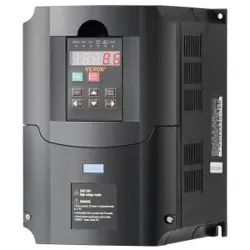
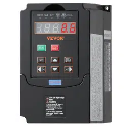
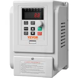
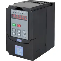
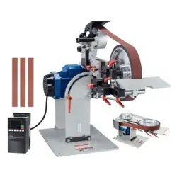
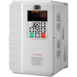
Inverter
MODEL:AT1-7500X
We continue to be committed to provide you tools with competitive price.
"Save Half", "Half Price" or any other similar expressions used by us only represents an
estimate of savings you might benefit from buying certain tools with us compared to the major
top brands and does not necessarily mean to cover all categories of tools offered by us. You
are kindly reminded to verify carefully when you are placing an order with us if you are
actually saving half in comparison with the top major brands.

- 1 -
MODEL:AT1-7500X
Have product questions? Need technical support? Please feel free to
contact us:
Technical Support and E-Warranty Certificate
www.vevor.com/support
NEED HELP? CONTACT US!
This is the original instruction, please read all manual instructions
carefully before operating. VEVOR reserves a clear interpretation of our
user manual. The appearance of the product shall be subject to the
product you received. Please forgive us that we won't inform you again if
there are any technology or software updates on our product.
Inverter

- 2 -
IMPORTANT SAFEGUARDS
Read all safety warnings, instructions, illustrations and
specifications provided with this inverter. Failure to follow all
instructions listed below may result in electric shock, fire
and/or serious injury.
WARNING :
This equipment is a high voltage device, please do not attempt to
disassemble this equipment at any time to avoid danger. After a device
failure, if the external switch fails to restart the device, please contact your
reseller for handling.
WARNING: ELECTRICAL SHOCK AND FIRE HAZARD!
1. Failure to comply with this instruction could result in an electrical failure,
fire and electrocution.
2. DO NOT DISASSEMBLE .
3. Do not submerge inverter .
4. Do not connect two or more transformers in parallel
5. Plug the power supply unit directly into a GFCI wet location outlet .
6. Do not use an extension cord
7. Installation of this inverter and related wiring must be done by aqualified
electrician in compliance with all applicable electrical codes.
WARNING :
Changes or modifications to this unit not expressly approved by the party
responsible for compliance could void the users authority to operate the
equipment .
SAVE THESE INSTRUCTIONS

- 3 -
FCC Information
CAUTION: Changes or modifications not expressly approved by the party
responsible for compliance could void the user's authority to operate the
equipment!
This device complies with Part 15 of the FCC Rules. Operation is subject to
the following two conditions:
1) This product may cause harmful interference.
2) This product must accept any interference received, including
interference that may cause undesired operation.
WARNING: Changes or modifications to this product not expressly
approved by the party.responsible for compliance could void the user's
authority to operate the product.
Note: This product has been tested and found to comply with the limits for
a Class B digital device pursuant to Part 15 of the FCC Rules, These limits
are designed to provide reasonable protection against harmful interference
in a residential installation.
This product generates, uses and can radiate radio frequency energy, and
if not installed and used in accordance with the instructions, may cause
harmful interference to radio communications. However, there is no
guarantee that interference will not occur in a particular installation. If this
product does cause harmful interference to radio or television
reception,which can be determined by turning the product off and on, the
user is encouraged to try to correct the interference by one or more of the
following measures.
Reorient or relocate the receiving antenna.
Increase the distance between the product and receiver.
Connect the product to an outlet on a circuit different from that to which
the receiver is connected.
Consult the dealer or an experienced radio/TV technician for
assistance.
- 4 -
Correct Disposal
This product is subject to the provision of European Directive
2012/19/EC. The symbol showing a wheelie bin crossed
through indicates that the product requires separate refuse
collection in the European Union. This applies to the product
and all accessories marked with this symbol. Products marked as such
may not be discarded with normal domestic waste, but must be taken to a
collection point for recycling electrical and electronic device
1. Product information
The manual provides precautions and guidance for user type selection,
installation, parameter setting, site commissioning, fault diagnosis and
daily maintenance and maintenance
1.1 Inverter series
1.2 Product Specification
Project
Standard
Basic
Function
System
Current vector universal frequency converter
with high fusion of performance and function.
Drive
performance
High-efficiency drive of the Induction Motor
Maximal
Frequency
Vector control: 0-500Hz
V/F control: 0-3200Hz.
Carrier
Frequency
0.5KHz-16KHz
The carrier frequency can be adjusted
automatically according to the load
Frequency
resolution
resolution
Digital setting: 0.01Hz
Simulation setting: ±0.025%
Control Mode
Open-loop vector control (SVC)
AT901 series
Braking Resistor
Model
Adaptive motor
Output
Current:A
W
Ohm
KW
HP
22
901-7K5G1
7.5
10
34.0
600
40

- 5 -
Project
Standard
V/F control
Starting torque
Type-G Mode: 0.3Hz/150% (SVC).
Type-P Mode: 0.3Hz/100%
Range of ADJ
Speed
1:100(SVC)
Stable speed
accuracy
±0.5%(SVC)
Overload
capacity
Type G:150% Rated Current 120s;180% for
10s
Type P:120% Rated Current for 60s;150% for
3s
Torque rise
Automatic torque increase;
Manual torque increase: 0.1% -30.0%
V/F curve
Three ways: straight line; multi-point; N
secondary V / F curve (1.2,1.4,1.6,1.8, and 2)
Curve Acc/
Dec mode
Line or S curve acceleration and deceleration
mode, four Acc/Dec times, Acc/Dec time range
0.0-6500.0s
DC Braking
Brake frequency: 0.00Hz-Maximum
frequency; Brake time:.0s-36.0s
Brake current value: 0.0% -100.0%
Jog control
Jog frequency range: 0.00Hz-50.00Hz;
Acc & Dec time: 0.0s-6500.0s.
Up to 16 segment speed runs with a built-in PLC or control
terminal
built-in PID
It can easily realize the process control
closed-loop control system
AVR Function
When the input voltage jitter, the output
voltage can be automatically kept constant
Stall control
Automatically limited the current and voltage
to prevent frequent over voltage tripping.
Fast current
limiting
Minimize the over current fault and protect the
normal operation of the frequency converter
Torque limit
and control
Automatically limit the torque during operation
to prevent frequent overcurrent tripping, and
Instant power
non-stop
When instantaneous power failure is
achieved, load feedback energy
Timing
Set the time range of 0.0Min-6500.0Min.
Operating
Command
source
Control panel,Control terminal, Serial port,can
be switched in multiple ways

- 6 -
Project
Standard
Frequency
source
Panel potentiometer, Number given,External
analog voltage/current input, and serial port
input.can be switched in multiple ways
Input Terminal
Five digital input terminals
1 analog quantity input terminal;
One 0-10V voltage or 0-20mA current input;
Output
Terminal
1 digital output terminal
1 relay output terminal(TA,TB,TC)
1 analog output terminal, supporting 0-10V or
0-20mA voltage output
Protection
function
Power on motor short circuit detection, input
and output phase loss protection, over current
protection, over voltage protection, under
voltage protection, overheating protection and
overload protection,etc
Loop The
environment
Use place
Indoor, not direct sunlight, no dust, corrosive
gas, combustible gas, oil fog, steam, water or
salt, etc
Above sea
level
under 1000m 2C116699
Ambient
temperature
-10℃ ~ + 40℃ (ambient temperature is 40℃
~50℃, please decrease the amount)
humidity
Less than 95%RH, anhydrous condensation
vibrate
Less than 5.9m/s (0.6g)
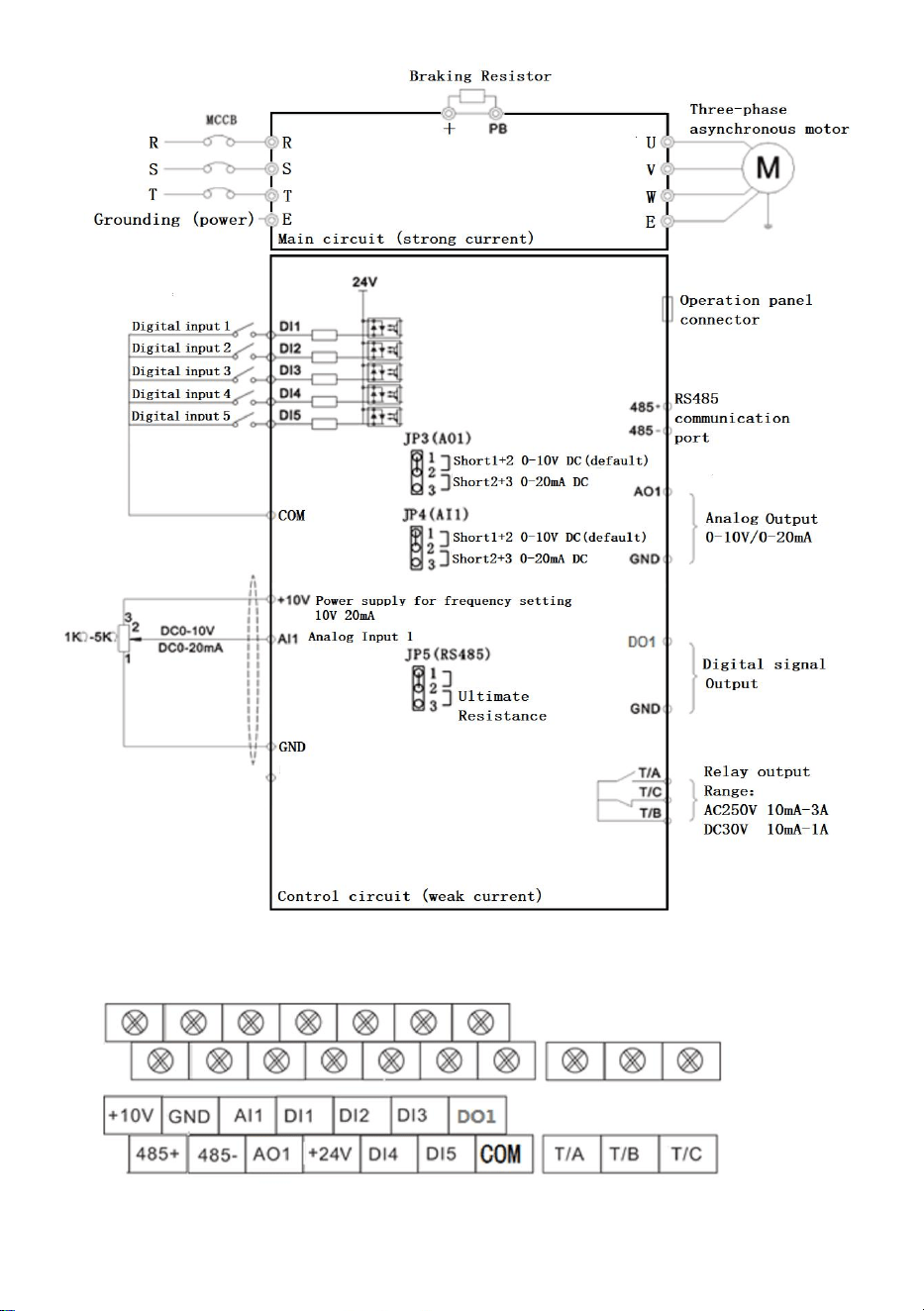
1.3 Description of the control loop and the main loop terminal
- 7 -
Figure 1-3-1 0.75-11.0KW wiring diagram control terminal description
- 8 -
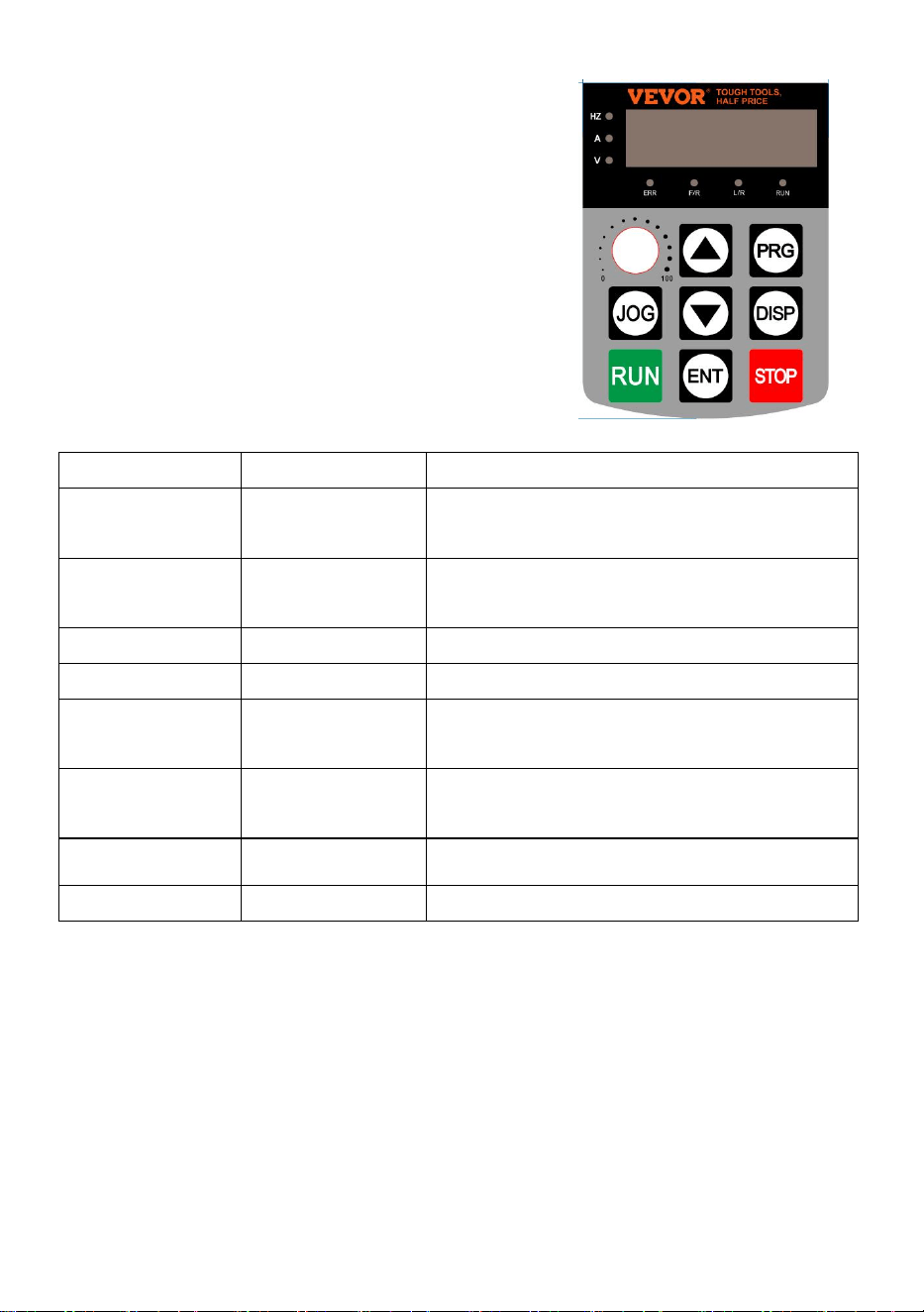
2. Operation and display
Function indicator lamp description
◈ Hz:Frequency display indicator lamp
◈ V: Voltage indicator lamp
◈ A: Current indicator lamp
◈ ERR: fault indicator lamp
◈ F / R: Forward and Reverse indicator lamp
◈ L / R: Communication control indicator lamp
◈ RUN: Running indicator lamp
Set the parameter method:
1. Press the PRG button to display the P 0.00,
2. The ▲ ▼ and DISP keys select the parameter number to modify, and the
ENTER key enters the parameter,
3. ▲ ▼ and DISP keys modify parameter values, ENTER key save parameters,
4. If you need to modify other parameters, repeat 2,3, steps, such as modification
completion, Return to the frequency interface using the PRG key.
Key symbol
Name
Function declaration
PRG
Programming
key
Menu enters or exits, with parameter
modification
ENT
Determine the
key
Enter the menu and confirm the
parameter setting
▲
Upper key
Increment of data or function codes
▼
Down key
Diminishing data or function codes
DISP
Shift key
Select the parameter modifier bit and the
display contents
RUN
Run the key
Start the inverter under the keyboard
operation mode
STOP
Stop / Reset key
Stop / reset operation,
JOG
Jog key
Limited to the P08.01 function code

- 9 -
3. Summary table of functional parameters:
P00, Monitoring group
P00.00
running frequency
0.00 ~ 320.00Hz(P01.22=2)
-
P00.01
Set the Frequency
0.0 ~ 3200.0Hz(P01.22=1)
-
P00.02
Busbar voltage (V)
0.0V ~ 3000.0V
-
P00.03
Output voltage (V)
0V ~ 1140V
-
P00.04
Output Current (A)
0.00A ~ 655.35A
-
P00.05
Output power (kW)
0 ~ 32767
-
P00.06
Output torque (%)
-200.0% ~ 200.0%
-
P00.07
DI input state
0 ~ 32767
-
P00.08
DO output state
0 ~ 1023
-
P00.09
AI1 voltage (V)
0.01V
-
P00.10
AI2 Voltage (V) or current (mA)
0.00V ~ 10.57V
0.00mA ~ 20.00mA
-
P00.12
count value
0 ~ 65535
-
P00.13
Length value
0 ~ 65535
-
P00.14
Load speed display
0 ~ 65535
-
P00.15
PID setting
0 ~ 65535
-
P00.16
PID feedback
0 ~ 65535
-
P00.17
PLC stage
0 ~ 65535
-
P00.18
Pulse input frequency
0 ~ 100kHz
-
P00.19
Feedback speed (Hz)
-320.00Hz ~ 320.00Hz
-3200.0Hz ~ 3200.0Hz
-
P00.20
Runtime Remaining
0.0 ~ 6500.0Min
-
P00.21
AI1 Voltage before correction
0.000V ~ 10.570V
-
P00.22
AI2 Voltage/Current before
correction
0.000V ~ 10.570V
0.000mA ~ 20.000mA
-
P00.24
linear speed
0 ~ 65535m/Min
-
P00.25
Current power time
0 ~ 6500Min
-
P00.26
Current running time
0.0 ~ 6500.0Min
-
P00.28
Communication setting
-100.00% ~ 100.00%
-

- 10 -
P00.30
Frequency X Display
0.00Hz ~ 500.00Hz
-
P00.31
Frequency Y Display
0.00Hz ~ 500.00Hz
-
P00.32
View any memory address value
0 ~ 65535
-
P00.35
Target torque, (%)
0.0°~ 359.9°
-
P00.37
Power factor Angle
-
P00.39
Target voltage of VF separating
0V ~ Motor rated voltage
-
P00.40
Output voltage of VF separating
0V ~ Motor rated voltage
-
P00.41
DI input status display
-
-
P00.42
DO input status display
-
-
P00.43
DI function status display 1
(function 01. function 40)-
-
P00.44
DI function status visual display 2
(Function 41. Function 80)-
-
P00-45
fault message
-
-
P00-59
Set the frequency of (%)
-100.00% ~ 100.00%
-
P00-60
Running frequency (%)
-100.00% ~ 100.00%
-
P00-61
Inverter state
0 ~ 65535
-
★—modifiable parameter under any condition
☆—not modifiable parameter under run status
●—the actual detected parameter, not modifiable
FC
name
Set range
Factory
value
modify
P01 Basic functional Group
P01.00
G/P type
1: Type G (constant torque load
model)
2: Type P (fan and water pump
model)
1
☆
P01.01
1. Motor control
mode
0: Speed Sensorless Vector
Control
2: V/F control model
2
★
P01.02
Operation
command
0: Operation panel run command
channel ("L/R" lights off)
0
☆

- 11 -
channel
1: Terminal Run channel ("L/R"
lights on)
2: Communication command
channel
("L/R" lights flashing)
P01.03
Main frequency
source X
0: Digital set (preset frequency
P01.08, keypad ▲/▼ key,power
loss)
1: Digital set (preset frequency
P01.08, keypad ▲/▼ key,Power
drop memory)
2: AI1 analog set (0-10V);
3: AI2 analog set(0-10V or
20mA);
4: Panel Potentiometer;
5: Pulse set (0~50KHZ DI5);
6: Multistage speed run set
7: Simple PLC set;
8: PID Control set;
9: Communication set.
4
★
P01.04
Secondary
frequency source
Y
Same as P01.03 (Main
frequency source X ) set
0
★
P01.05
Limit selection of
Y when frequency
superposition
0: Compared to the 【P01.10】
Maximum frequency
1: Relative to the frequency
source X
0
☆
P01.06
Limit of Y when
frequency
superposition
0% ~150%
100%
☆
P01.07
Frequency source
Single digit: Frequency source
selection
0: Main frequency source X
1: Main and Secondary operation
00

- 12 -
results (operation relationship is
determined by Ten digits)
2: Main frequency X and
Secondary frequency Y switch
3: Switch between main
frequency X and Main and
Secondary operation results
4: The frequency Y switches with
Main and Secondary operation
results
Ten digits: Frequency operation
relationship of X and Y
0: X +Y
1: X -Y
2: Maximum of the Two, 3:
Minimum of the Two.
P01.08
Preposition
frequency
0.00Hz ~ Maximum frequency
【P01.10】
50.00
Hz
☆
P01.09
Running direction
0: Consistent direction, 1:
Opposite direction
0
☆
P01.10
Maximum output
frequency
Vector: 50.00Hz ~ 500.00Hz
V/F: 50.00Hz ~
2000.00Hz
50.00
Hz
★
P01.11
Upper limit
frequency
source
0: 【P01.12】 Set up
1: AI1 Set up
2:Al2 Set up
3: AI3 Set up
4: Pulse set (0~50KHZ DI5);
5: Communication Setup
0
★
P01.12
Upper limiting
frequency
【P01.14】~ 【P01.10】
50.00
Hz
☆
P01.13
Upper limit
frequency bias
0.00Hz ~【P01.10】
0.00Hz
☆

- 13 -
P01.14
Lower limit
frequency
0.00Hz ~【P01.12】
0.00Hz
☆
P01.15
Carrier frequency
0.5kHz ~ 16.0kHz
For Model
☆
P01.16
Carrier frequency
Adjust with
temperature
0: No,1: Yes
1
☆
P01.17
Acceleration time
1
0.00s ~ 650.00s(P01.19=2)
0.0s ~ 6500.0s(P01.19=1)
0s ~ 65000s(P01.19=0)
Reference frequency【P01.25】
For Model
☆
P01.18
Deceleration time
1
☆
P01.19
Time unit of
Acceleration and
deceleration time
0: 1 seconds
1: 0.1 seconds
2: 0.01 seconds
1
☆
P01.21
Bias frequency of
frequency Y
when
superposition
0.00Hz ~ Maximum output
frequency【P01.10】
0.00Hz
☆
P01.22
Resolution of
Frequency
Resolution of all frequency
commands.
2
★
P01.23
Power down
memory for
Digital Frequency
setting
0: No memory 1: Memory
0
☆
P01.24
Motor parameter
group selection
0: Motor parameter group 1,
1: Motor parameter group 2.
0
★
P01.25
Reference
frequency of
Acceleration and
deceleration time
0: Maximum frequency【P01.10】
1: Setting frequency
2:100Hz
0
★
P01.26
Runtime
frequency
instruction
UP/DOWN
0: Operation frequency,
1: Setting frequency
0
★

- 14 -
benchmark
P01.27
Command source
bundled
frequency source
Single digit: Operation Panel
command binding frequency
source selection
0: No binding 1: Digital set
2:AI1 3:AI2 4:AI3
5: Pulse set (0~50KHZ DI5);
6: Multi segment speed;
7: Simple PLC
8:PID
9: Communication Set
Ten digit: Terminal command
binding frequency source
selection
100 digit: communication
command binding frequency
source selection
Thousand digit: Automatically run
the binding frequency source
selection
0000
☆
P02 Asynchronous Motor parameter group 1
P02.00
Motor type
0: Ordinary asynchronous motor,
1: Variable frequency
asynchronous motor
0
★
P02.01
Rated power of
motor
0.1kW ~ 400.0kW
According
to the
Model
Of the
Inverter
★
P02.02
Rated voltage of
Motor
1V ~ 2000V
★
P02.03
Rated current of
Motor
0.01A ~ 655.35A
(Inverter power <=55kW)
0.1A ~ 6553.5A
(Inverter power> 55kW)
★

- 15 -
P02.04
Rated frequency
of motor
0.01Hz~ Maximum output
frequency【P01.10】
★
P02.05
Rated speed of
motor
1rpm ~ 65535rpm
★
P02.06
Stator resistance
of motor
0.001Ω ~ 65.535Ω (Inverter
power <=55kW)
0.0001Ω ~ 6.5535Ω (Inverter
power> 55kW)
Tuning
Parameter
★
P02.07
Rotor resistance
of Motor
0.001Ω ~ 65.535Ω (Inverter
power <=55kW)
0.0001Ω ~ 6.5535Ω (Inverter
power> 55kW)
★
P02.08
Leak resistance
of Motor
0.01mH ~ 655.35mH
(Inverter power <=55kW)
0.001Mh ~ 65.535mH
(Inverter power> 55kW)
★
P02.09
Mutual resistance
of Motor
0.1mH ~ 6553.5mH (Inverter
power <=55kW)
0.01mH ~ 655.35mH
(Inverter power> 55kW)
★
P02.10
No-load current of
the Motor
0.01A ~ P02.03 (Inverter
power <=55kW)
0.1A ~ P02.03 (Inverter
power > 55kW)
★
P02.37
Tuning selection
0: no-operation
1: Tuning at Motor stationary 1
2: Motor dynamic tuning
3: Tuning at Motor completely
stationary 2
0
★
P03 Vector control parameters of motor group1
P03.00
Speed loop
proportional 1
1 ~ 100
30
☆

- 16 -
P03.01
Speed loop
integration time 1
0.01s ~ 10.00s
0.50s
☆
P03.02
Switch frequency
1
0.00 ~ 【P03.05】
5.00Hz
☆
P03.03
Speed loop
proportional 2
1 ~ 100
20
☆
P03.04
Speed loop
integration time 2
0.01s ~ 10.00s
1.00s
☆
P03.05
Switch frequency
2
P03.02 ~Maximum output
frequency【P01.10】
10.00Hz
☆
P03.06
Vector control of
the shift gain
50% ~ 200%
100%
☆
P03.07
SVC torque
filtering time
constants
0.000s ~ 0.100s
0.050s
☆
P03.09
Torque upper limit
source under
speed control
mode
0: P03.10 setting
1:AI1; 2:AI2;
3: AI3;
4: Pulse set (DI5);
5: Communication Setting;
6: MIN (AI1, AI2)
7: MAX (AI1, AI2)
0
☆
P03.10
Upper torque limit
under speed
control mode
0.0% ~ 200.0%
150.0%
☆
P03.13
Proportional gain
of
excitation
regulation
0 ~ 60000
2000
☆
P03.14
Integral gain of
excitation
regulation
0 ~ 60000
1300
☆
P03.15
Proportional gain
0 ~ 60000
2000
☆

- 17 -
of
torque regulation
P03.16
Integral gain of
torque regulation
0 ~ 60000
1300
☆
P04 V/F Control Parameters
P04.00
VF curve setting
0: linear curve V/ F
1: Multipoint curve V/ F
2: Decreasing torque curve 1
(Square curve)
3: Decreasing torque curve 2
(1.2 power)
4: Decreasing torque curve 2
(1.4 power)
6: Decreasing torque curve 2
(1.6 power)
8: Decreasing torque curve 2
(1.8 power)
10: VF completely separation
mode
11: VF semi-separation mode
0
★
P04.01
Torque boost
setting
0.0% (Automatic lifting torque);
0.1%~30.0%
By Model
☆
P04.02
Torque boost
cutoff point
0.00Hz ~Maximum output
frequency【P01.10】
50.00Hz
★
P04.03
Multi-point V/F
Freq. 1
0.00Hz ~ 【P04.05】
0.00Hz
★
P04.04
Multi-point V/F
Voltage 1
0.0% ~ 100.0%
0.0%
★
P04.05
Multi-point V/F
Freq. 2
【P04.03】 ~ 【P04.07】
0.00Hz
★
P04.06
Multi-point V/F
Voltage 2
0.0% ~ 100.0%
0.0%
★

- 18 -
P04.07
Multi-point V/F
Freq. 3
【P04.05】~ Motor Rated
frequency 【P02.04】
0.00Hz
★
P04.08
Multi-point V/F
Voltage 3
0.0% ~ 100.0%
0.0%
★
P04.09
V/F control Slip
frequency
compensation
0.0% ~ 200.0%
0.0%
☆
P04.10
V/F Over
excitation gain
0 ~ 200
64
☆
P04.11
Oscillation
suppression gain
for V/F
0 ~ 100
By Model
☆
P04.13
Voltage source by
VF separated
0: Digital Settings 【P04.14】
1: AI1 2:AI2
3:AI3
4: Pulse Setting (DI5)
5: Multiple instruction
6: Simple PLC
7: The PID
8: communication Setting
Note: 100.0%, corresponding to
the motor rated voltage
0
☆
P04.14
Voltage for VF
separation
0V ~ Motor rated voltage
0V
☆
P04.15
Voltage rise time
of VF separation
0.0s ~ 1000.0s
Note: Time when 0V rises to
rated voltage of motor。
0.0s
☆
P04.16
Voltage dorp time
of VF separation
0.0s ~ 1000.0s
Note: Time when Rated voltage
of motor dorp to 0V
0.0s
☆
P04.17
Shutdown mode
of VF separation
0: The frequency and voltage
drop to 0 separately;
1: Frequency drops after the
Voltage drop to 0
0
☆

- 19 -
P04.18
Over-current stall
action current
50% ~ 200%
150%
★
P04.19
Suppression of
Over current stall
0: Disable,
1: Enable.
1
★
P04.20
Suppression’s
gain of Over
current stall
0 ~ 100
20
☆
P04.21
Compensation
coefficient of
action Over
current stall
50% ~ 200%
50%
★
P04.22
Over-voltage stall
action voltage
650.0V ~ 800.0V
760.0V
★
P04.23
Suppression of
Over-voltage stall
0: Disable,
1: Enable.
1
★
P04.24
Suppression’s
Freq. gain of
Over-voltage stall
0 ~ 100
30
☆
P04.25
Suppression’s
Voltage gain of
Over-voltage stall
0 ~ 100
30
☆
P04.26
Maximum rise
frequency limit for
Over-voltage stall
0 ~ 50Hz
5Hz
★
P05 group, Input Parameters
P05.00
DI1 terminal
function
0: No function;
1: Forward running(FWD) or
Running;
2:Reverse running (REV) or
Forward/Reverse switch
3: three-wire running control
4: forward jog control (FJOG)
5: Reverse jog control (RJOG)
1
★

- 20 -
6: Freq. Increase(Terminal UP)
7: Freq. decrease(Terminal
DOWN)
8: Free shutdown control
9: External reset signal
input(RST)
10: Suspend operation;
11: External fault normally-open
(NO) input
12: Multi-speed 1
13: Multi-speed 2
14: Multi-speed 3
15: Multi-speed 4
16: ACC/DEC time select 1( TT1)
17: ACC/DEC time select 2( TT2)
18: Frequency source switch
19: UP/DOWN Freq. zero
clearing (terminal, keyboard)
20: Run command Switch
terminal 1
21: VFD ACC/DEC prohibit
22: PID control Pause
23: PLC state reset
24: Pendulum frequency Pause
25: Counter input
26: Counter reset
27: Length count input
28: Length reset
29: Torque control Disable
30: Pulse Setting (only DI5 can
setting, P05.04=30)
31: Reserved;
32: DC braking immediately;
33: External fault input(normally

- 21 -
closed,NC)
34: Frequency modification
Enables
35: PID input signal reversed;
36: External parking terminal 1
37: Run command Switch
terminal 2
38: PID integral Pause;
39: Frequency X switches with
the Preset frequency
40: Frequency Y switches with
the Preset frequency
41: Motor selection terminal 1
43: The PID Parameters switch
44: User defined fault 1
45: User defined fault 2
46: Speed control / Torque
control switch
47: Emergency stop
48: External parking terminal 2
49: Slow ate DC braking
50: Run time cleared;
51: Two-wire control / Three-wire
control switch
52: Reversal Disable;
P05.01
DI2 terminal
functional
4
★
P05.02
DI3 terminal
functional
9
★
P05.03
DI4 terminal
functional
12
★
P05.04
DI5 terminal
function
(only DI5 can
13
★

- 22 -
setting Pulse
function,
P05.04=30)
P05.10
DI filtering time
0.000s ~ 1.000s
0.010s
☆
P05.11
Terminal control
Mode
0: Two-wire control mode 1,
1: Two-wire control mode 2,
2: Three-wire control mode 1,
3: Three-wire control mode 2.
0
★
P05.12
Frequency
adjusting step
size
0.001Hz/s ~ 65.535Hz/s
1.00Hz/s
☆
P05.13
Min. input of AI
curve 1
0.00V ~ P05.15
0.00V
☆
P05.14
Corresponding
value of AI curve
1's Min. input
-100.0% ~ +100.0%
0.0%
☆
P05.15
Max. input of AI
curve 1
P05.13 ~ +10.00V
10.00V
☆
P05.16
Corresponding
value of AI curve
1's Max. input
-100.0% ~ +100.0%
100.0%
☆
P05.17
AI curve 1 filtering
time
0.00s ~ 10.00s
0.10s
☆
P05.18
AI curve 2's Min.
input
0.00V ~ P05.20
0.00V
☆
P05.19
Corresponding
value of AI curve
2's Min. input
-100.0% ~ +100.0%
0.0%
☆
P05.20
Max. input of AI2
P05.18 ~ +10.00V
10.00V
☆
P05.21
Corresponding
value of AI curve
2's Max. input
-100.0% ~ +100.0%
100.0%
☆

- 23 -
P05.22
AI curve 2 filtering
time
0.00s ~ 10.00s
0.10s
☆
P05.23
AI curve 3's Min.
input
-10.00V ~ P05.25
-10.00V
☆
P05.24
Corresponding
value of AI curve
3's Min. input
-100.0% ~ +100.0%
0.0%
☆
P05.25
Max. input of AI
curve 3
P05.23 ~ +10.00V
10.00V
☆
P05.26
Corresponding
value of AI curve
3's Max. input
-100.0% ~ +100.0%
100.0%
☆
P05.27
AI curve 3 filtering
time
0.00s ~ 10.00s
0.10s
☆
P05.28
Min. value of
Pulse input
-10.00V ~ P05.25
0.00V
☆
P05.29
Corresponding
value of Pulse's
Min. input
-100.0% ~ +100.0%
0.0%
☆
P05.30
Max. value of
Pulse input
P05.23 ~ +10.00V
10.00V
☆
P05.31
Corresponding
value of Pulse's
Max. input
-100.0% ~ +100.0%
100.0%
☆
P05.32
Pulse filtering
time
0.00s ~ 10.00s
0.10s
☆
P05.33
AI curve selection
Single bit: AI1 curve selection
1: AI curve 1
(2 PM, see P05.13 ~ P05.16.)
2: AI curve 2
(2 PM, see P05.18 ~ P05.21.)
3: AI curve 3
(2 PM, see P05.23 ~ P05.26.)
321
☆

- 24 -
4: AI curve 4
(4 PM, see P24.00~P24.07)
5: AI curve 4
(4 PM, see P24.08~P24.15)
Ten bit: AI2 curve selection (the
same as Single bit 1~5)
Hundred bit: AI3 curve selection
(the same as above)
P05.34
The AI is below
the minimum
input setting
selection
Single bit: AI1 below Min. input
setting
0: Corresponding value of Min.
input
1: 0.0%
Ten bit: AI2 below Min. input
setting
(the same as Single bit 1~2)
Hundred bit: AI3 below Min. input
setting
(the same as above)
000
☆
P05.35
DI1 delay time
0.0s ~ 3600.0s
0.0s
★
P05.36
DI2 delay time
0.0s ~ 3600.0s
0.0s
★
P05.37
DI3 delay time
0.0s ~ 3600.0s
0.0s
★
P05.38
DI1-DI5 terminal
valid
mode selection
0: High level effective, 1: Low
level effective
Single Bit: DI1;
Ten Bit: DI2;
Hundreds Bit: DI3;
Thousand Bit: DI4,
Ten thousand Bit: DI5
00000
★
P05.39
DI6-D17 terminal
valid
mode selection
0: High level effective, 1: Low
level effective
Single Bit: DI6,
00000
★

- 25 -
Ten Bit: DI7
P06 group, Output Parameters
P06.01
DO1 output
function selection
0: No output
1: Running indicator;
2: Fault output (for free shutdown
fault)
3: Freq. level detection signal
1(P14T1)
4: Frequency arrival
indicator(FAR)
5: VFD zero-speed
running(When running)
6: Motor overload Early-warning
7: Inverter overload
Early-warning
8: The Set Count arrives
9: The specified count is reached
10: Length is reached
11: The PLC cycle is completed
12: Accumulated running time
arrives
13: Frequency limiting
14: Torque limiting
15: Ready to run
16:AI1>AI2
17: Output freq. reaches Upper
limit
18: Output freq. reaches Lower
limit(When running)
19: Under pressure state output
20: Communication setting
21: Location is complete
(reserved)
0
☆
P06.02
Control Board
Relay
(TA- TB- TC)
Function
Selection
2
☆

- 26 -
22: Location proximity (reserved)
23: Zero-speed running 2 (also
output when shutdown)
24: Accumulated power-on time
arrives
25: Freq. level detection signal
2(P14T2)
26: Output freq. 1 reached
27: Output freq. 2 reached
28: Output Current 1 reached
29: Output Current 2 reached
30: Regularly reached
31: Input signal Al1 overrun
32: Load dropping
33: VFD reverse running
34: Zero-current state
35: The Power module
temperature arrives
36: Output current out of limit
37:Output freq. reaches Lower
limit(shutdown also output)
38: Fault output (all faults)
39: Motor overheating
Early-warning
40: This running time arrives
41: Fault output (for free
shutdown fault and no under
pressure output)
P06.07
AO1 output
function selection
0: Operation freq.,
1: Set freq.
2: Output current,
3: Output torque,
4: Output power,
5: Output voltage,
0
☆
P06.08
AO2 output
function selection
1
☆

- 27 -
6: Input pulse freq.
7:AI1 8:AI2
9:AI3
10: Length
11: Count value
12: Communication setting,
13: Motor speed
14: Output Current. (100.0%
Corresponding to 1000.0A)
15: Output voltage (100.0%
Corresponding to 1000.0V)
16: Motor output torque
(Percentage of actual value
relative to motor rating)
17: VFD output torque
(Percentage of actual value
relative to VFD rating)
P06.10
AO1 zero-bias
coefficient
-100.0% ~ +100.0%
0.0%
☆
P06.11
AO1 gain
-10.00 ~ +10.00
1.00
☆
P06.12
AO2 zero-bias
coefficient
-100.0% ~ +100.0%
0.0%
☆
P06.13
AO2 gain
-10.00 ~ +10.00
1.00
☆
P06.17
DO output delay
time
0.0s ~ 3600.0s
0.0s
☆
P06.18
RELAY output
delay time
0.0s ~ 3600.0s
0.0s
☆
P06.19
RELAY2 output
delay time
0.0s ~ 3600.0s
0.0s
☆
P06.22
DO output valid
status selection
0: Positive logic, 1: Anti-logic
Single Bit: DO
Ten bit: RELAY1
00000
☆

- 28 -
Hundred Bit: RELAY2
P07 group, Start and Stop control Parameters
P07.00
Starting mode
0: Direct start
1: Start with speed tracking
2: DC braking + start at start
frequency
0
☆
P07.01
Speed tracking
method
0: Start with the shutdown
frequency
1: Start with the working
frequency
2: Start at the maximum
frequency
0
★
P07.02
Speed of Speed
tracking
1 ~ 100
20
☆
P07.03
Start frequency
0.00Hz ~ 10.00Hz
0.00Hz
☆
P07.04
Start-frequency
hold time
0.0s ~ 100.0s
0.0s
★
P07.05
DC brake current
at startup
0% ~100%
0%
★
P07.06
DC brake time at
startup
0.0s ~100.0s
0.0s
★
P07.07
Accelerating
and
Decelerating
mode
0: linear Acc/Dec mode
1: S curve Acc/Dec mode A
2: S curve Acc/Dec mode B
0
★
P07.08
Time ratio of Start
segment in S
curve
0.0% ~ (100.0%-P07.09)
30.0%
★
P07.09
Time ratio of Start
segment in S
curve
0.0% ~ (100.0%-P07.08)
30.0%
★

- 29 -
P07.10
Stop mode
0:Decelerate to stop 1:Coast to
stop
0
☆
P07.11
Frequency
threshold of DC
brake
0.00Hz ~ Maximum freq.
【P01.10】
0.00Hz
☆
P07.12
DC brake delay
time
0.0s ~ 100.0s
0.0s
☆
P07.13
DC brake current
0% ~ 100%
0%
☆
P07.14
DC brake time at
stop
0.0s ~ 100.0s
0.0s
☆
P07.15
DC Brake
utilization rate
0% ~ 100%
100%
☆
P07.18
Speed tracking
current
30% ~ 200%
★
P08 Group Keyboards and Display Parameters
P08.01
M key function
0: The M key is invalid
1: Switch between Remote
Control (Terminal or
Communication control) and
Operation Panel Control, when
【P01.02】 =1 or 2
2: FWD/REV switch
3: FJOG (Forward jog control)
4: RJOG (Reverse jog control)
0
★
P08.02
STOP/RESET
key function
0: The STOP/RES key Only valid
in panel control mode
1: The STOP/RES key Always
valid
1
☆
P08.03
LED displays
parameter 1in
Operation status
0000 ~ FFFF
Bit00: Running Frequency 1 (Hz)
Bit01: Setting Frequency (Hz)
Bit02: Bus Voltage (V)
1F
☆

- 30 -
Bit03: Output Voltage (V)
Bit04: Output current (A)
Bit05: Output power (kW)
Bit06: Output torque (%)
Bit07: DI input status
Bit08: DO output status
Bit09: AI1 voltage (V)
Bit10: AI2 voltage (V)
Bit11: AI3 voltage (V)
Bit12: Count value
Bit13: Length value
Bit14: Load speed display
Bit15: PID settings
P08.04
LED displays
parameter 2in
Operation status
0000 ~ FFFF
Bit00: PID feedback
Bit01: PLC stage
Bit02: PULSE Input frequency
(kHz)
Bit03: Running Frequency 2 (Hz)
Bit04: Remaining runtime
Bit05:AI1-corrected front voltage
(V)
Bit06:AI2-corrected front voltage
(V)
Bit07:AI3-corrected front voltage
(V)
Bit08: Line speed
Bit09: Current Power Time
(Hour)
Bit10: Current Runtime (Min)
Bit11:PULSE Input frequency
(Hz)
Bit12: Communication Setting
Value
0
☆

- 31 -
Bit13: Encoder feedback speed
(Hz)
Bit14: Main Frequency X Display
(Hz)
Bit15: Secondary frequency Y
Display (Hz)
P08.05
LED displays
parameter in Stop
status
0000 ~ FFFF
Bit00: Set Frequency (Hz)
Bit01: Bus Voltage (V)
Bit02: DI input status
Bit03: DO output status
Bit04: AI1 voltage (V)
Bit05: AI2 voltage (V)
Bit06: AI3 voltage (V)
Bit07: Count value
Bit08: Length value
Bit09: PLC stage
Bit10: Load speed
Bit11: PID settings
Bit12: PULSE Input frequency
(kHz)
33
☆
P08.06
Load speed
display factor
0.0001 ~ 6.5000
1.0000
☆
P08.07
Power module
temperature
0.0℃ ~ 100.0℃
-
●
P08.08
Product number
-
-
●
P08.09
Cumulative
running time
0h ~ 65535h
-
●
P09 group, auxiliary function
P09.00
Jog frequency
0.00Hz ~ Maximum freq.
【P01.10】
2.00Hz
☆
P09.01
Jog Acc time
0.0s ~ 6500.0s
20.0s
☆

- 32 -
Recommended time:
0.4 ~ 4.0KW 7.5S
5.5 ~ 30.0KW 15.0S
37.0 ~ 132.0KW 40.0S
160.0~ 630.0KW 60.0S
P09.02
Jog Dec time
20.0s
☆
P09.03
Acceleration time
2
15.0
☆
P09.04
Deceleration time
2
☆
P09.05
Acceleration time
3
☆
P09.06
Deceleration time
3
☆
P09.07
Acceleration time
4
☆
P09.08
Deceleration time
4
☆
P09.09
Hopping freq. 1
0.00Hz ~ Maximum freq.
【P01.10】
0.00Hz
☆
P09.10
Hopping freq. 2
0.00Hz
☆
P09.11
Hopping freq.
range
0.01Hz
☆
P09.12
Positive and
Reverse dead
time
0.0s ~ 3000.0s
0.0s
☆
P09.13
Reverse
frequency
permission
0: Allowed; 1:
Prohibit
0
☆
P09.14
When the setting
freq. is lower than
the lower limit of
freq.
0: Run at a lower limit frequency
1: Stop
2: zero-speed operation
0
☆
P09.15
Drop control
0.00Hz ~ 10.00Hz
0.00Hz
☆
P09.16
Setting
cumulative power
on arrival time
0h ~ 65000h
0h
☆

- 33 -
P09.17
Setting
cumulative
running arrival
0h ~ 65000h
0h
☆
P09.18
Start protection
0: Unprotected;
0
☆
P09.19
Frequency
detection value 1
(P14T1)
0.00Hz ~ Maximum freq.
【P01.10】
50.00
Hz
☆
P09.20
Frequency
detection lag
value (P14T1)
0.0% ~ 100.0% (P14T1 level)
5.0%
☆
P09.21
Frequency
reaches the
detected width
0.0% ~ 100.0% (Maximum
frequency)
0.0%
☆
P09.22
Frequency
hopping function
During Acc and
Dec.
0: Invalid, 1: valid
0
☆
P09.25
Switching freq. of
acceleration time
1 and time 2
0.00Hz ~ Maximum freq.
【P01.10】
0.00Hz
☆
P09.26
Switching freq. of
deceleration time
1 and time 2
0.00Hz ~ Maximum freq.
【P01.10】
0.00Hz
☆
P09.27
Terminal Jog
priority
0: Invalid, 1: valid
0
☆
P09.28
Frequency
detection value 2
(P14T2)
0.00Hz ~ Maximum frequency
50.00
Hz
☆
P09.29
Frequency
detection lag
value (P14T2)
0.0% ~ 100.0% (P14T2 level)
5.0%
☆
P09.30
Arbitrary arrival
frequency
0.00Hz ~ Maximum frequency
50.00
Hz
☆

- 34 -
detection value 1
P09.31
Arbitrary arrival
frequency
detected width 1
0.0% ~ 100.0% (Maximum
frequency)
0.0%
☆
P09.32
Arbitrary arrival
frequency
detection value 2
0.00Hz ~ Maximum frequency
50.00
Hz
☆
P09.33
Arbitrary arrival
frequency
detected width 2
0.0% ~ 100.0% (Maximum
frequency)
0.0%
☆
P09.34
Zero-current
detection level
0.0% ~ 300.0%
100.0% corresponds to the
motor rated current
5.0%
☆
P09.35
Delay time of
Current detect
0.01s ~ 600.00s
0.10s
☆
P09.36
Current value of
output over
current
0.0% (Not detect)
0.1% ~ 300.0% (Motor rated
current)
200.0%
☆
P09.37
Delay time of
Output Over
current Detection
0.00s ~ 600.00s
0.00s
☆
P09.38
Arbitrary arrival
current 1
0.0% ~ 300.0% (Motor rated
current)
100.0%
☆
P09.39
Arbitrary arrival
current 1 width
0.0% ~ 300.0% (Motor rated
current)
0.0%
☆
P09.40
Arbitrary arrival
current 2
0.0% ~ 300.0% (Motor rated
current)
100.0%
☆
P09.41
Arbitrary arrival
current 2 width
0.0% ~ 300.0% (Motor rated
current)
0.0%
☆
P09.42
Timer function
selection
0: Invalid, 1: valid
0
☆
P09.43
Timer runtime
0: P09.44 setting,
0
☆

- 35 -
selection
1: AI1
2: AI2
3: AI3
Analog input range corresponds
to the【P09.44】
P09.44
Timer running
time
0.0Min ~ 6500.0Min
0.0Min
☆
P09.45
AI1 input voltage
protection value
lower limit
0.00V ~ P09.46
3.10V
☆
P09.46
AI1 input voltage
protection value
upper limit
P09.45 ~ 10.00V
6.80V
☆
P09.47
Over temp.
protection Value
0℃ ~ 100 ℃
75℃
☆
P09.48
Cooling fan
control
0: Fan running during VDF
running
1: Always running when power
on;
0
☆
P09.49
Wake up
frequency
Hibernate frequency (P09.51) ~
Maximum freq.【P01.10】
0.00Hz
☆
P09.50
Wake up delay
time
0.0s ~ 6500.0s
0.0s
☆
P09.51
Sleep frequency
0.00Hz ~ Wake-Up Frequency
【P09.49】
0.00Hz
☆
P09.52
Sleep delay time
0.0s ~ 6500.0s
0.0s
☆
P09.53
Arrival time of this
operation
0.0 ~ 6500.0Min
0.0Min
☆
P09.54
Correction factor
of Output power
0.00% ~ 200.0%
100.0%
☆
P10 group Fault and Protection

- 36 -
P10.00
Motor overload
protection
0: Disable,
1: Enable
1
☆
P10.01
Motor overload
protection gain
0.20 ~ 10.00
1.00
☆
P10.02
Motor overload
early-warning
factor
50 ~ 100%
80%
☆
P10.07
Short circuit to
ground protection
when power on
0: Disable,
1: Enable
1
☆
P10.08
Brake unit's
starting voltage
650.0V ~ 800.0V
690V
☆
P10.09
Automatic fault
reset times
0 ~ 20
0
☆
P10.10
DO action
selection during
automatic fault
reset
0: No Action
1: Action
0
☆
P10.11
Interval for
Automatic fault
reset
0.1s ~ 100.0s
1.0s
☆
P10.12
Input phase loss
protection/
Power relay pull
in protection
Single Bit: Input phase loss
protection
0: Disable,
1: Enable
Ten Bit: Power relay pull in
protection
0: Disable,
1: Enable
11
☆
P10.13
Output phase
loss protection
0: Disable,
1: Enable
1
☆
P10.14
First-time failure
type
0: No fault
1: (Reserved)
-
●

- 37 -
2: Over-current in Acc process
3: Over-current in Dec process
4: Over-current in constant
speed
5: Over-voltage in Acc process
6: Over-voltage in Dec process
7: Over-voltage in constant
speed
8: Buffer resistance overload
9: Under-voltage
10: VFD overload
11: Motor overload
12: Input phase loss
13: Output phase loss
14: Power module is overheated
15: External fault
16: Communication exception
17: Power relay is abnormal
18: Abnormal current detection
19: Motor tuning is abnormal
21: Parameter read and write
exception
22: Other Hardware abnormal
23: Motor short-circuit to ground
26: Run-time arrival
27: User Custom fault 1
28: User Custom fault 2
29: Power-on time arrives
30: Load drop
31: Runtime PID feedback is lost
40: Fast flow limit timeout
41: Switch the motor during
operation
42: Speed deviation is too large
P10.15
Second failure
type
-
●
P10.16
Third (most
recent) fault type
-
●

- 38 -
43: Motor over-speed
P10.17
Frequency at the
third (most
recent) failure
-
-
●
P10.18
Current at the
third (most
recent) fault
-
-
●
P10.19
Bus voltage at the
third (most
recent) fault
-
-
●
P10.20
Input terminal
status at the third
(most recent)
failure
-
-
●
P10.21
Output terminal
status at the third
(most recent)
failure
-
-
●
P10.22
The Inverter
status at the third
(most recent)
failure
-
-
●
P10.23
Power-on time for
the third (most
recent) failure
-
-
●
P10.24
Run time for the
third (most
recent) failure
-
-
●
P10.27
Frequency at the
second failure
-
-
●
P10.28
Current at the
second failure
-
-
●

- 39 -
P10.29
Bus voltage at the
second fault
-
-
●
P10.30
Input terminal
status for the
second failure
-
-
●
P10.31
Output terminal
status at the
second failure
-
-
●
P10.32
The Inverter
status at the
second failure
-
-
●
P10.33
Power-on time for
the second failure
-
-
●
P10.34
Run time for the
second failure
-
-
●
P10.37
Frequency at the
first failure
-
-
●
P10.38
Current at the first
failure
-
-
●
P10.39
Bus voltage at the
first failure
-
-
●
P10.40
Input terminal
status at the first
failure
-
-
●
P10.41
Output terminal
status at the first
failure
-
-
●
P10.42
The Inverter
status at the first
failure
-
-
●
P10.43
Power-on time for
the first failure
-
-
●
P10.44
Run time for the
-
-
●

- 40 -
first failure
P10.47
Fault protection
action
selection 1
Single Bit: Motor overload (Err11)
Ten Bit: Input phase loss, (Err12)
Hundred Bit: Output phase loss,
(Err13)
Thousand Bit: External fault
(Err15)
Ten thousand Bit:
Communication exception,
(Err16)
0: Coast to stop;
1: Stop by Stop mode【P07.10】
2: Keep running;
00000
☆
P10.48
Fault protection
action
selection 2
Single Bit/Hundred Bit/Thousand
Bit: (Reserved)
Ten Bit: Parameter read and
write exception (Err21)
Ten thousand Bit: Run-time
arrival (Err26)
0: Coast to stop;
1: Stop by Stop mode【P07.10】
00000
☆
P10.49
Fault protection
action
selection 3
Single Bit: User Custom fault 1
(Err27)
Ten Bit:: User Custom fault 2
(Err28)
Hundred Bit: Power-on time
arrives (Err29)
Thousand Bit: Load drop (Err30)
0: Coast to stop;
1: Stop by Stop mode【P07.10】
2: Jump to 7% of the Rated freq.
of the Motor and keep running,
Operate return to Set freq. when
00000
☆

- 41 -
load recovery
Ten thousand Bit: PID feedback
loss (Err31)
0: Coast to stop;
1: Stop by Stop mode【P07.10】
2: Keep running;
P10.50
Fault protection
action selection 4
Single Bit: Speed deviation too
large (Err42)
Ten Bit: Motor over-speed
(Err43)
Hundred Bit: (Reserved)
Thousand Bit: Speed feedback
error (Err52)
0: Coast to stop;
1: Stop by Stop mode【P07.10】
2: Keep running;
00000
☆
P10.54
Keep running
freq. selection
when failure
0: The current frequency
1: The setting frequency
2: Run at upper limit frequency
3: Run at lower limit frequency
4: Run at abnormal reserve
frequency
0
☆
P10.55
Abnormal reserve
frequency
0.0%~100.0% (100.0%
corresponds to Max freq
【P01.10】
100.0%
☆
P10.59
Instant power
non-stop
0: Invalid 1: Reduce the
speed; 2: Deceleration stop
0
☆
P10.60
The Pause
judgment voltage
of Instant power
non-stop
80.0% ~ 100.0% (Standard
bus voltage)
90.0%
☆
P10.61
Voltage recovery
Judgment time of
Instant power
0.00s ~ 100.00s
0.50s
☆

- 42 -
non-stop
P10.62
The judgment
voltage of Instant
power non-stop
60.0% ~ 100.0% (Standard bus
voltage)
80.0%
☆
P10.71
Gain of Instant
power non-stop
0 ~ 100
40
☆
P10.72
Integral
coefficient of
Instant power
non-stop
0 ~ 100
30
☆
P10.73
Deceleration time
of Instant power
non-stop
0 ~ 300.0s
20.0s
★
P10.63
Load drop
protection
selection
0: Invalid,
1: valid
0
☆
P10.64
Load drop
detection level
0.0 ~ 100.0%
10.0%
☆
P10.65
Load drop
detection time
0.0 ~ 60.0s
1.0s
☆
P10.67
Over-speed
detection value
0.0% ~ 50.0% (Max freq
【P01.10】)
20.0%
☆
P10.68
Over-speed
detection time
0.0s: Non-detectable
0.1 ~ 60.0s
1.0s
☆
P10.69
The detection
value for Speed
deviation too
large
0.0% ~ 50.0% (Max freq
【P01.10】)
20.0%
☆
P10.70
The detection
time for Speed
deviation too
large
0.0s: 0.1 ~ 60.0s
5.0s
☆

- 43 -
P11 group PID function
P11.00
PID input channel
0: P11.01 setting
1:AI1
2:AI2
3:AI3
4: Pulse Setting (DI5)
5: Communication Setting
6: Multistage speed
7: Keyboard encoder settings
0
☆
P11.01
Digital reference
input setting
0.0~ 10.00
3.00
☆
P11.02
PID feedback
channel
0:AI1
1:AI2 2:AI3
3: AI1-AI2
4: Pulse Setting (DI5)
5: Communication Setting
6:AI1+AI2
7:MAX(|AI1|, |AI2|)
8:MIN (|AI1|, |AI2|)
0
☆
P11.03
PID polarity
0: Positive direction,
1: Negative direction
0
☆
P11.04
Range of PID
feedback
0 ~ 100.00KG
10.00
☆
P11.05
Proportional gain
KP02
0.0 ~ 100.0
20.0
☆
P11.06
Integration time
Ti1
0.01s ~ 10.00s
2.00s
☆
P11.07
Derivative time
Td1
0.000s ~ 10.000s
0.000s
☆
P11.08
PID reversal
cutoff freq
0.00 ~ Maximum frequency
2.00Hz
☆
P11.09
The limit of PID
deviation
0.0% ~ 100.0%
1.0%
☆

- 44 -
P11.10
Differential limiter
of PID
0.00% ~ 100.00%
0.10%
☆
P11.11
PID Input signal
change time
0.00 ~ 650.00s
0.00s
☆
P11.12
PID feedback
filtering time
0.00 ~ 60.00s
0.00s
☆
P11.13
The PID output
filtering time
0.00 ~ 60.00s
0.00s
☆
P11.15
Proportional gain
KP03
0.0 ~ 100.0
20.0
☆
P11.16
Integration time
Ti2
0.01s ~ 10.00s
2.00s
☆
P11.17
Derivative time
Td2
0.000s ~ 10.000s
0.000s
☆
P11.18
The PID
parameter
switching
conditions
0: No switch
1: Switch via the DI terminal
2: Automatic switch according to
the deviation
0
☆
P11.19
The PID
parameter
switching
Deviation 1
0.0% ~ P11.20
20.0%
☆
P11.20
The PID
parameter
switching
Deviation 2
P11.19 ~ 100.0%
80.0%
☆
P11.21
Initial value of PID
0.0% ~ 100.0%
0.0%
☆
P11.22
Holding time of
PID Initial
0.00 ~ 650.00s
0.00s
☆
P11.23
Max positive
deviation of Two
output
0.00% ~ 100.00%
1.00%
☆

- 45 -
P11.24
Max deviation
deviation of Two
output
0.00% ~ 100.00%
1.00%
☆
P11.25
The PID integral
property
Single Bit: Integral separation
0: Invalid, 1: valid
Ten Bit: when the frequency
reaches the limits
0: Continue integral regulation,
1: Stop integral regulation
00
☆
P11.26
PID feedback
loss detection
values
0.1% ~ 100.0% (0.0%:
Not detection)
0.0%
☆
P11.27
PID feedback
loss detection
time
0.0s ~ 20.0s
0.0s
☆
P11.28
The PID
shutdown
operation
0: Stop without PID operation,
1: Stop with PID operation
0
☆
P12 group -Swing frequency, Fixed length and Counting
P12.00
Mode of Swing
freq setting
0: Relative to the Central
frequency【P01.07】
1: Relative to the Max freq
【P01.10】
0
☆
P12.01
Range of Swing
frequency
0.0% ~ 100.0%
0.0%
☆
P12.02
The Range of the
jump freq
0.0% ~ 50.0%
0.0%
☆
P12.03
Cycle of Swing
frequency
0.1s ~ 3000.0s
10.0s
☆
P12.04
Rise time of
swing freq 's
triangular wave
0.1% ~ 100.0%
50.0%
☆

- 46 -
P12.05
Setting length
0m ~ 65535m
1000m
☆
P12.06
Actual length
0m ~ 65535m
0m
☆
P12.07
Number of pulses
per Meter
0.1 ~ 6553.5
100.0
☆
P12.08
Setting Count
value
1 ~ 65535
1000
☆
P12.09
Specifies Count
value
1 ~ 65535
1000
☆
P13 group Multistage speed, simple PLC
P13.00
Multistage speed
0 (MS0)
-100.0% ~ 100.0% (Max freq
【P01.10】)
0.0%
☆
P13.01
Multistage speed
1 (MS1)
0.0%
☆
P13.02
Multistage speed
2 (MS2)
0.0%
☆
P13.03
Multistage speed
3 (MS3)
0.0%
☆
P13.04
Multistage speed
4 (MS4)
0.0%
☆
P13.05
Multistage speed
5 (MS5)
0.0%
☆
P13.06
Multistage speed
6 (MS6)
0.0%
☆
P13.07
Multistage speed
7 (MS7)
0.0%
☆
P13.08
Multistage speed
8 (MS8)
0.0%
☆
P13.09
Multistage speed
9 (MS9)
0.0%
☆
P13.10
Multistage speed
10 (MS10)
0.0%
☆

- 47 -
P13.11
Multistage speed
11 (MS11)
0.0%
☆
P13.12
Multistage speed
12 (MS12)
0.0%
☆
P13.13
Multistage speed
13 (MS13)
0.0%
☆
P13.14
Multistage speed
14 (MS14)
0.0%
☆
P13.15
Multistage speed
15 (MS15)
0.0%
☆
P13.16
Simple PLC
operation mode
0: End of single operation
1: Final value at end of single
operation
2: Always cycle
0
☆
P13.17
PLC running state
saving after
power off
Single Bit: when Power drop
Ten Bit: when Stop
0: Not save
1: Saving.
00
☆
P13.18
Multistage speed
0 runtime
0.0s(h)~6553.5s(h)
0.0s (h)
☆
P13.19
Acc/Dec time of
MS 0
0 ~3
0
☆
P13.20
Multistage speed
1 runtime
0.0s(h)~ 6553.5s(h)
0.0s (h)
☆
P13.21
Acc/Dec time of
MS 1
0 ~ 3
0
☆
P13.22
Multistage speed
2 runtime
0.0s(h) ~ 6553.5s(h)
0.0s (h)
☆
P13.23
Acc/Dec time of
MS 2
0 ~ 3
0
☆
P13.24
Multistage speed
3 runtime
0.0s(h) ~ 6553.5s(h)
0.0s (h)
☆
P13.25
Acc/Dec time of
0 ~ 3
0
☆

- 48 -
MS 3
P13.26
Multistage speed
4 runtime
0.0s(h) ~ 6553.5s(h)
0.0s (h)
☆
P13.27
Acc/Dec time of
MS 4
0 ~ 3
0
☆
P13.28
Multistage speed
5 runtime
0.0s(h) ~ 6553.5s(h)
0.0s (h)
☆
P13.29
Acc/Dec time of
MS 5
0 ~ 3
0
☆
P13.30
Multistage speed
6 runtime
0.0s(h) ~ 6553.5s(h)
0.0s (h)
☆
P13.31
Acc/Dec time of
MS 6
0 ~ 3
0
☆
P13.32
Multistage speed
7 runtime
0.0s(h) ~ 6553.5s(h)
0.0s (h)
☆
P13.33
Acc/Dec time of
MS 7
0 ~ 3
0
☆
P13.34
Multistage speed
8 runtime
0.0s(h) ~ 6553.5s(h)
0.0s (h)
☆
P13.35
Acc/Dec time of
MS 8
0 ~ 3
0
☆
P13.36
Multistage speed
9 runtime
0.0s(h) ~6553.5s(h)
0.0s (h)
☆
P13.37
Acc/Dec time of
MS 9
0 ~ 3
0
☆
P13.38
Multistage speed
10 runtime
0.0s(h) ~ 6553.5s(h)
0.0s (h)
☆
P13.39
Acc/Dec time of
MS 10
0 ~ 3
0
☆
P13.40
Multistage speed
11 runtime
0.0s(h)~6553.5s(h)
0.0s (h)
☆
P13.41
Acc/Dec time of
MS 11
0 ~ 3
0
☆

- 49 -
P13.42
Multistage speed
12 runtime
0.0s(h) ~ 6553.5s(h)
0.0s (h)
☆
P13.43
Acc/Dec time of
MS 12
0 ~ 3
0
☆
P13.44
Multistage speed
3 runtime
0.0s(h) ~ 6553.5s(h)
0.0s (h)
☆
P13.45
Acc/Dec time of
MS 3
0 ~ 3
0
☆
P13.46
Multistage speed
14 runtime
0.0s(h) ~ 6553.5s(h)
0.0s (h)
☆
P13.47
Acc/Dec time of
MS 14
0 ~ 3
0
☆
P13.48
Multistage speed
15 runtime
0.0s(h) ~ 6553.5s(h)
0.0s (h)
☆
P13.49
Acc/Dec time of
MS 15
0 ~ 3
0
☆
P13.50
Unit of Multistage
speed’s Acc/Dec
time
0: s (seconds)
1: h (hours)
0
☆
P13.51
Signal source of
Multistage speed
0 (MS0)
0: Parameter 【P13.00】
1:AI1 2:AI2
3:AI3
4: Pulse (DI5)
5: PID
6: Preposition frequency
【P01.08】
7: Can be modified by ▲/▼ key
0
☆
P14 group RS485 Communication parameters
P14.00
Baud rate setting
for RS485
Single Bit: MODBUS
0:300BPS 1:600BPS
2:1200BPS 3:2400BPS
4:4800BPS 5:9600BPS
6:19200BPS 7:38400BPS
5
☆

- 50 -
8:57600BPS 9:115200BPS
P14.01
MODBUS Data
format
0: No check (8.N-2)
1: Parity check (8.E-1)
2: Odd check (8.O-1)
3: No check (8.N-1)
0
☆
P14.02
Local address
0:broadcast address
1~247:(MODBUS)
1
☆
P14.03
MODBUS
Response delay
0 ~ 20ms
2
☆
P14.04
Timeout time of
RS485
0.0: Invalid
0.1 ~ 60.0s
0.0
☆
P14.05
MODBUS
Protocol selection
0: Non-standard MODBUS
protocol
1: Standard MODBUS protocol
1
☆
P14.06
Current
Resolution of 485
read
0:0.01A
1:0.1A
0
☆
P15 group Special parameters for constant pressure water supply
P15.00
Simple macro
debugging
function
0: No function
1: One drive two pumps
2: Water supply in the building
community
3: Hotel water supply
4: Fire water supply
5: Booster pump
6: Deep water pump
0
☆
P15.01
Wake up
pressure
0~ Sleep pressure 【P15.04】
KG(1KG=0.1Mpa)
2.50KG
☆
P15.02
Delay time of
Wake up
0.0s~6500.0s
0s
☆
P15.03
Sleep pressure
Wake up pres 【P15.01】 ~
Pressure Gauge Range(0.1Mpa)
3.50KG
☆

- 51 -
P15.04
Sleep delay time
0.0s~6500.0s
60.0s
☆
P15.05
Pressure
proportional
linkage
0: Disable;
1: Enable
1
☆
P15.06
Wake-up
pressure
difference
0~100.0Bar(Kg,0.1Mpa)
0.50KG
☆
P15.07
Sleep pressure
difference
0~100.0Bar(Kg)
0.50KG
☆
P15.08
Over-pressure
alarm value
0.00~Pressure Gauge Range
KG(1KG=0.1Mpa=1Bar)
9.00KG
☆
P15.09
Delay Time of
Over-pressure
alarm
0-6553.5S
0.0S
☆
P15.10
Low-pressure
alarm value
0.00~Pressure Gauge Range
KG(1KG=0.1Mpa=1Bar)
The parameter opens the low
pressure reach alarm.
0.0KG
☆
P15.11
Low-pressure
alarm delay time
0-6553.5S
20.0S
☆
P15.12
water Intake
start-up pressure
0~Pressure Gauge Range KG
Open the water Intake start-stop
control via P01.02=3
The water inlet must use the
current sensor of the AI2
For the voltage sensor, change
the AI2 jumper
3.00KG
☆
P15.13
Inlet shutdown
pressure
0~Pressure Gauge Range KG
(Bar)
3.20KG
☆
P15.14
Number of
auxiliary pumps
0~3
0
☆
P15.15
waiting time of
Auxiliary pump
0~1000.0S
60.0S
☆

- 52 -
turns on
P15.16
Waiting time for
the auxiliary
pump switch
0~1000.0S
5.0S
☆
P15.17
RO1 Relay ON
frequency setting
0~50HZ
When reaches the value, the
Relay will ON
50.00
☆
P15.18
RO1 Relay OFF
frequency setting
0~50HZ
When reaches the value, the
Relay will OFF
30.00
☆
P15.19
Signal source of
Water level
controller
0: Function is not valid
1: AI1
2:AI2
3: AI3
P15.19=1~3 ,The
(P15.20,P15.21,P15.22,P15.23)
setting is valid, P15.19=0,
parameters Not Valid.
0
☆
P15.20
Sleeping Valve for
the Water level
Controller
0.0~100.0%
The signal is less than this
parameter continue【P15.21】
time, Sleep and full water
warning(ErrH)
25.0%
☆
P15.21
Full water level
delay
0~1000.0S 【P15.20】’s delay
time setting.
6.0S
☆
P15.22
Water empty
delay for Water
level controller
0~1000.0S
In the full water warning(ErrH)
state, when Water level controller
signal is greater than the
P15.20,and continue【P15.22】
times, the full water warning is
clear and restored to the normal
state.
60.0S
☆

- 53 -
P15.23
Judgment value
for Hydraulic
probe
damage(Water
level controller)
0.0% : Invalid function.
0.1~100.0%: when Water level
controller signal is greater than
the【P15.23】 , show (E.tSF)
fault and shut down
0.0%
☆
P15.24
Water shortage
protection
function
0: Disable;
1: Enable, and judge by
frequency and pressure
0
☆
P15.25
Water shortage
fault check value
0.00 ~ Setting value KG
(Bar/0.1Mpa)
Valid when the P15.19=1,
The water shortage is
determined when the feedback
value is less than this value
0.50
☆
P15.26
Water shortage
protection
detection
frequency
0~50.00HZ
Valid when the P15.19=1 when
the operation frequency is
greater than or equal to this
frequency, and the pressure is
lower than or equal to
15.25,Judge water shortage.
50.00
☆
P15.27
Delay time of
water shortage
protection
detection
0~6553.5S
Delay time for water shortage
fault alarm Judgement.
10
☆
P15.28
Effective pressure
of incoming water
0~Pressure Gauge Range KG
(Bar/0.1Mpa)
3.00
☆
P15.29
Incoming water
detection time
0~9999S
Time for incoming water
detection
20.0S
☆
P15.30
Water leakage
and restart
deviation amount
0~Pressure Gauge Range KG
(Bar/0.1Mpa)
0
☆

- 54 -
P15.31
Water leakage
and then start the
return value
0~Pressure Gauge Range KG
(Bar/0.1Mpa)
0
☆
P15.32
Water leakage
and then start the
return value
detection time
0: NO Function
0.1.10.0S
2.0S
☆
P15.33
Sleep mode
0: Disable
1: Sleep when pressure is
greater than sleep pressure;
2: Sleep when running frequency
is less than sleep frequency
(affected by P15.29)
3: Sleep when pressure is
greater than sleep pressure and
running frequency is less than
sleep frequency.
0
☆
P15.34
Sleep output
frequency
0~P01.12
20.0Hz
☆
P17 group Functional code management
P17.00
User password
0 ~ 65535
0
☆
P17.01
Parameter
initialization
0: No operation
01: Restore factory parameters,
excluding motor parameters
02: clear record information
0
★
P17.04
The Function
code modifies the
properties
0: Modifiable
1: Not modifiable
0
☆
P18 group Torque control parameters
P18.00
Speed/Torque
control mode
0: Speed control,
1: Torque control
0
★

- 55 -
P18.01
Torque setting
source selection
under torque
control mode
0: Digital Settings
1: (P18.03)
1:AI1
2:AI2
3: AI3
4: PLUSE Setting
5: Communication setting
6: MIN (AI1, AI2)
7: MAX (AI1, AI2)
0
★
P18.03
Digital Setting
under the torque
control mode
-200.0% ~ 200.0% (P18.01=0)
150.0%
☆
P18.05
The Max
forward freq for
Torque controls
0.00Hz ~ Max freq【P01.10】
50.00Hz
☆
P18.06
The Max
reverse freq for
Torque controls
0.00Hz ~ Max freq【P01.10】
50.00Hz
☆
P18.07
Torque control 's
Acc time
0.00s ~ 65000s
0.00s
☆
P18.08
Torque control 's
Dec time
0.00s ~ 65000s
0.00s
☆
P23 group Control optimization parameters
P23.00
Upper limit
frequency for
DPWM switch
5.00Hz ~ Max freq【P01.10】
8.00Hz
☆
P23.01
PWM modulation
mode
0: Asynchronous modulation,
1: Synchronous modulation
0
☆
P23.03
Random PWM
depth
0: Invalid Random PWM
1 ~ 10: Random depth of PWM
carrier frequency
0
☆
P23.04
Fast flow
limiting
0: Disable,
1: Enable
1
☆

- 56 -
P23.06
Under-voltage
value Setting
200.0V ~ 2200.0V
350V
☆
P23.09
Over-pressure
Value setting
200.0V ~ 2200.0V
270V
★
P23.10
Automatic carrier
freq change at
low frequency
0: Disable,
1: Enable
1
☆
P23.11
Zero-speed
running output
control
0: Disable,
1: Enable
1
☆
P23.12
Sensitivity of
Power phase loss
protection
0~30.0%
13.0%
☆
P24 group AI curve setting
P24.00
Min input of the AI
curve 4
-10.00V~P24.02
0.00V
☆
P24.01
Corresponding
ratio of P24.00
-100.0%~+100.0%
0.0%
☆
P24.02
Turning 1 of the
AI curve 4
P24.00~P24.04
3.00V
☆
P24.03
Corresponding
ratio of P24.02
-100.0%~+100.0%
30.0%
☆
P24.04
Turning 2 of the
AI curve 4
P24.02~P24.06
6.00V
☆
P24.05
Corresponding
ratio of P24.04
-100.0%~+100.0%
60.0%
☆
P24.06
Max input of the
AI curve 4
P24.06~+10.00V
10.00V
☆

- 57 -
P24.07
Corresponding
ratio of P24.06
-100.0%~+100.0%
100.0%
☆
P24.08
Min input of the AI
curve 5
-10.00V~P24.10
-10.00V
☆
P24.09
Corresponding
ratio of P24.08
-100.0%~+100.0%
-100.0%
☆
P24.10
Turning 1 of the AI
curve 5
P24.08~P24.12
-3.00V
☆
P24.11
Corresponding
ratio of P24.10
-100.0%~100.0%
-30.0%
☆
P24.12
Turning 2 of
the AI curve 5
P24.10~P24.14
3.00V
☆
P24.13
Corresponding
ratio of P24.12
-100.0%~100.0%
30.0%
☆
P24.14
Max input of
the AI curve 5
P24.12~+10.00V
10.00V
☆
P24.15
Corresponding
ratio of P24.14
-100.0%~100.0%
100.0%
☆
P24.24
Jump point of
the Al1
-100.0%~100.0%
0.0%
☆
P24.25
Jump range of
the Al1
0.0%~100.0%
0.5%
☆
P24.26
Jump point of
the Al2
-100.0%~100.0%
0.0%
☆
P24.27
Jump range of
the Al2
0.0%~100.0%
0.5%
☆

- 58 -
P24.28
Jump point of
the Al3
-100.0%~100.0%
0.0%
☆
P24.29
Jump range of
the Al3
0.0%~100.0%
0.5%
☆
P30 group Correction for the AI and AO
P30.00
AI1 Measured
voltage 1
0.500V~4.000V
Factory
correction
☆
P30.01
AI1 display
voltage 1
0.500V~4.000V
Factory
correction
☆
P30.02
AI1 measured
voltage 2
6.000V~9.999V
Factory
correction
☆
P30.03
AI1 display
voltage 2
6.000V~9.999V
Factory
correction
☆
P30.04
AI2 Measured
voltage 1
0.500V~4.000V
Factory
correction
☆
P30.05
AI2 display
voltage 1
0.500V~4.000V
Factory
correction
☆
P30.06
AI2 measured
voltage 2
6.000V~9.999V
Factory
correction
☆
P30.07
AI2 display
voltage 2
6.000V~9.999V
Factory
correction
☆
P30.08
AI3 Measured
voltage 1
-9.999V~10.000V
Factory
correction
☆
P30.09
AI3 display
voltage 1
-9.999V~10.000V
Factory
correction
☆
P30.10
AI3 measured
voltage 2
-9.999V~10.000V
Factory
correction
☆

- 59 -
4. Fault alarm and Countermeasures
P30.11
AI3 display
voltage 2
-9.999V~10.000V
Factory
correction
☆
P30.12
AO1 target
voltage 1
0.500V~4.000V
Factory
correction
☆
P30.13
AO1
Measured
voltage 1
0.500V~4.000V
Factory
correction
☆
P30.14
AO1 target
voltage 2
6.000V~9.999V
Factory
correction
☆
P30.15
AO1
Measured
voltage 2
6.000V~9.999V
Factory
correction
☆
P30.16
AO2 target
voltage 1
0.500V~4.000V
Factory
correction
☆
P30.17
AO2
Measured
voltage 1
0.500V~4.000V
Factory
correction
☆
P30.18
AO2 target
voltage 2
6.000V~9.999V
Factory
correction
☆
P30.19
AO2
Measured
voltage 2
6.000V~9.999V
Factory
correction
☆
Displays
Fault name
Possible cause of
failure
Trouble shooting
Err01
Power module
protection
Motor power is too high
or Wiring short circuit or
Power module damaged
Remove the motor wire
and start it again. If
there is any problem,
repair the Inverter
Err02
Under voltage
fault
The input voltage is
abnormal or the Power
relay is not engaged or
the voltage detection
Check the power supply
voltage or seek service
from the manufacturer

- 60 -
fault
Err31
Over voltage
during
acceleration
The input voltage is
abnormal
Check the input power
supply
Restart when the motor
rotates
Set to start after DC
braking
Err32
Over voltage
during
deceleration
The deceleration time is
too short
Extend the deceleration
time
The input voltage is
abnormal
Check the input power
supply
Err33
Over voltage
at constant
speed
The input voltage is
abnormal
Check the input power
supply
Err60
Inverter
overload
Improper setting of V/F
curve or torque.
Adjust the V / F curve
and the torque boost
amount
Low input voltage.
Check the power supply
voltage
The acceleration time is
too short
Extend the acceleration
time
The motor load is too
heavy
Select a more powerful
Inverter
Err61
OverCurrent
during
acceleration
The acceleration time is
too short
Extend the acceleration
time

- 61 -
The Inverter power is too
small
Select Inverter with high
power level
Improper setting of V/F
curve or torque.
Adjust the V / F curve or
the torque boost
amount
Err62
OverCurrent
during
deceleration
The deceleration time is
too short
Extend the deceleration
time
The Inverter power is too
small
Select the Inverter with
high power level
Err63
OverCurrent
at constant
speed
Low input voltage.
Check the power supply
voltage
motor stall or load
mutation is too large
Check the load
The Inverter power is too
small
Select a more powerful
Inverter
Err64
Motor
overload
Improper setting of V/F
curve or torque.
Adjust the V / F curve or
the torque boost
amount
Low input voltage.
Check the power supply
voltage
motor stall or load
mutation is too large
Check the load
Motor overload
protection coefficient is
not set correctly
Set the motor overload
protection coefficient
correctly

- 62 -
Err65
Wave by
wave current
limiting fault
Same with motor
Overload
Same with motor
Overload
Err40
hardware
malfunction
Water, insects, etc
restart can not resume
back to the factory
repair
Err41
EEPROM
R/W failure
EEPROM hitch
Seek a service from the
manufacturer
Err42
Control power
failure
The input power supply is
not in the specification
range
Adjust the voltage to the
specification
requirements
Err46
Current
detection
failure
Current sampling circuit
fault
Seek a service from the
manufacturer
Drive circuit failure
Seek a service from the
manufacturer
Err11
External
equipment
failure 1
External fault input
terminal 1 is closed
Disconnect the External
fault terminal and clear
the fault (pay attention
to check the cause)
Err12
Communicatio
n failure
485 Communication
failed
Check the 485
connection
Err13
Accumulated
runtime
arrives
The cumulative running
time reaches the set
value
Clear record by
Parameter initialization
function
Err15
External
equipment
failure 2
External fault input
terminal 2 is closed
Disconnect the External
fault terminal and clear
the fault (pay attention
to check the cause)
Err16
Power on time
arrives
The cumulative power on
time reaches the set
value
Parameter initialization
function clear records

- 63 -
Err17
Contact / relay
failure
External equipment input
terminal fault
Disconnect the External
fault terminal and clear
the fault (pay attention
to check the cause)
Err08
Power module
overheated
Bad cooling fan or
overheated ambient
temperature
Check the Fan or heat
dissipation or wait for
cool to try again
Err90
Switching
motor fault at
runtime
Poor contact of motor
line or switch between
motor and Inverter
The Inverter must be
directly connected to
the motor to check that
the motor line is loose
Err91
Ground short
circuit fault
Short to earth fault
Disconnect ground line
(pay attention to check
the cause)
Err92
Input phase
loss
Check input power line
Seek a service from the
manufacturer
Err93
Output phase
loss
output power line loss or
a phase circuit for
detecting current is
abnormal
Check the output
voltage and Check
output power line
Err94
Motor
overspeed
failure
Motor speed exceeds the
normal speed
Check whether the load
has other power
Err95
Speed
deviation
failure
The speed gap is too
large than the normal
speed
Check the motor load
Err96
PID feedback
loss at
runtime
Poor contact with the PID
sensor signal
Check the sensor signal
Err97
Load drop
fault
Motor line is
disconnected
Check the motor line
Err98
Motor over
temperature
The motor overheat
Check motor
temperature

- 64 -
5. Setup Description
When the P17.00 is set to non-0 value,the parameter protection password
is set.You must enter the password before modifying the parameters.
Cancel the password, and the P17.00 needs to be set to 0.
The parameter menu in user custom parameter mode is not password
protected.
P01~P23 group is basic function parameter,
P00 group is monitoring function parameter.
The symbols in the function table are described as follows:
"☆": The set value of this parameter can be changed when the Inverter is
Stop and Running state;
"★": The set value of this parameter cannot be changed when the Inverter
is in the running state;
"●": The value of the parameter is the actual detected record value and
cannot be changed;
"*": It means that the parameter is the "Manufacturer Parameter" and is
limited to the manufacturer setting to prohibit the user from operating.
Made In China
Err99
Motor tuning
fault
The motor parameters
are not set according to
the nameplate or the
motor line is in poor
contact
Set the motor
parameters according to
the nameplate and
check the lead from the
Inverter to the motor
ErrH1
Water
shortage
Water shortage failure
Check for lack of water
ErrH2
Full water
early warning
The water is full
Restore normal water
pressure
ErrH3
High water
pressure
failure
Force shutdown failure
Too high water
pressure, check the
water pressure


MODÈLE:AT17500X
Nouscontinuonsànousengageràvousfournirdesoutilsàdesprixcompétitifs.
«Économisezlamoitié»,«Moitiéprix»outouteautreexpressionsimilaireutiliséeparnousnereprésente
qu'uneestimationdeséconomiesquevouspourriezréaliserenachetantcertainsoutilscheznousparrapport
auxgrandesmarquesetnecouvrepasnécessairementtouteslescatégoriesd'outilsquenousproposons.
Nousvousrappelonsdebienvouloirvérifiersoigneusementlorsquevouspassezunecommandechez
noussivouséconomisezréellementlamoitiéparrapportauxgrandesmarques.
Onduleur
Assistancetechniqueetcertificatdegarantieélectroniquewww.vevor.com/support
Machine Translated by Google
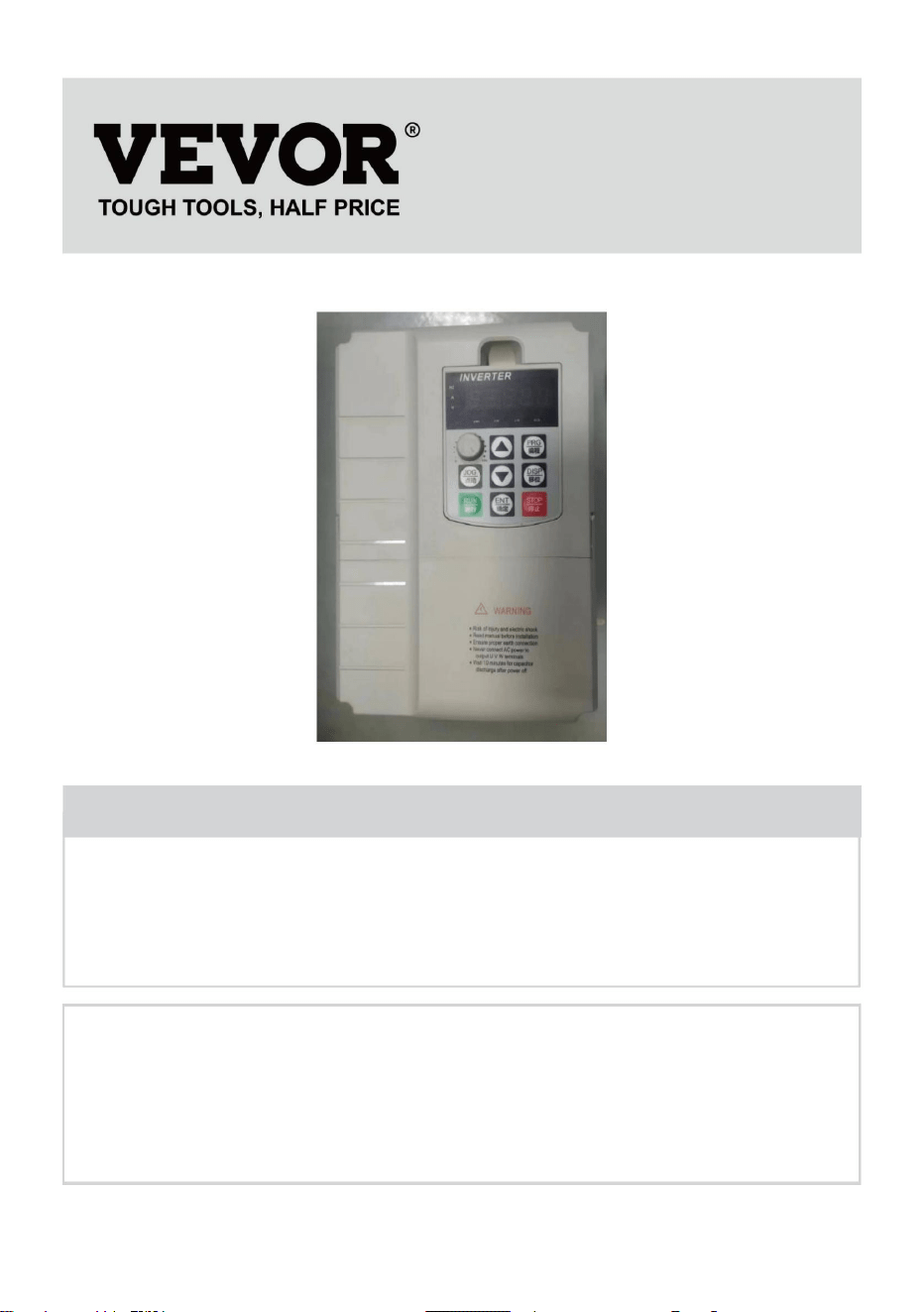
BESOIND'AIDE?CONTACTEZNOUS!
1
Vousavezdesquestionssurnosproduits?Vousavezbesoind'assistancetechnique?
N'hésitezpas
ànouscontacter:Assistancetechniqueetcertificatdegarantie
électroniquewww.vevor.com/support
MODÈLE:AT17500X
Ils'agitdelanoticed'utilisationd'origine.Veuillezlireattentivementtoutesles
instructionsdumanuelavantdel'utiliser.VEVORseréserveledroitd'interpréterclairement
notremanueld'utilisation.L'apparenceduproduitdépendduproduitquevousavez
reçu.Veuilleznousexcuser,nousnevousinformeronsplusencasdemiseàjourtechnologique
oulogicielledenotreproduit.
Onduleur
Machine Translated by Google

lesinstructionsénuméréescidessouspeuvententraînerunchocélectrique,unincendie
incendieetélectrocution.
6.N'utilisezpasderallonge
Leschangementsoumodificationsapportésàcetteuniténonexpressémentapprouvésparleparti
spécificationsfourniesaveccetonduleur.Lenonrespectdetoutesles
1.Lenonrespectdecetteinstructionpeutentraînerunepanneélectrique,
AVERTISSEMENT:
équipement.
AVERTISSEMENT:
2.NEPASDÉMONTER.
3.Nepasimmergerl’onduleur.
responsabledelaconformitépourraitannulerl'autoritédesutilisateursàexploiterle
et/oudesblessuresgraves.
démontezcetéquipementàtoutmomentpourévitertoutdanger.Aprèsunappareil
5.Branchezleblocd'alimentationdirectementsurunepriseGFCIpourendroithumide.
Cetéquipementestunappareilàhautetension,veuilleznepastenterde
4.Neconnectezpasdeuxouplusieurstransformateursenparallèle
Liseztouslesavertissementsdesécurité,instructions,illustrationset
AVERTISSEMENT:RISQUEDECHOCÉLECTRIQUEETD’INCENDIE!
7.L'installationdecetonduleuretlecâblageassociédoiventêtreeffectuésparuntechnicienqualifié.
électricienenconformitéavectouslescodesélectriquesapplicables.
revendeurpourlamanutention.
panne,silecommutateurexterneneparvientpasàredémarrerl'appareil,veuillezcontactervotre
CONSERVEZCESINSTRUCTIONS
MESURESDESÉCURITÉIMPORTANTES
2
Machine Translated by Google

équipement!
Remarque:Ceproduitaététestéetjugéconformeauxlimitesde
s'iln'estpasinstalléetutiliséconformémentauxinstructions,peutprovoquer
réception,quipeutêtredéterminéeenéteignantetenrallumantleproduit,le
responsabledelaconformitépourraitannulerl'autoritédel'utilisateuràexploiterle
autorisationd'exploiterleproduit.
leproduitprovoquedesinterférencesnuisiblesaveclaradiooulatélévision
lerécepteurestconnecté.
mesuressuivantes.
Réorienteroudéplacerl'antennederéception.Augmenter
ladistanceentreleproduitetlerécepteur.Connecterleproduitàuneprise
suruncircuitdifférentdeceluiauquelilestconnecté.
assistance.
lesdeuxconditionssuivantes:
sontconçuspourfourniruneprotectionraisonnablecontrelesinterférencesnuisibles
unappareilnumériquedeclasseBconformémentàlapartie15desrèglesdelaFCC.Ceslimites
l'utilisateurestencouragéàessayerdecorrigerl'interférenceparuneouplusieursdes
Cetappareilestconformeàlapartie15desrèglesdelaFCC.Sonfonctionnementestsoumisà
2)Ceproduitdoitacceptertouteinterférencereçue,ycompris
Ceproduitgénère,utiliseetpeutémettredel'énergieradiofréquence,et
Consultezlerevendeurouuntechnicienradio/TVexpérimentépour
1)Ceproduitpeutprovoquerdesinterférencesnuisibles.
dansuneinstallationrésidentielle.
ATTENTION:Leschangementsoumodificationsnonexpressémentapprouvésparlapartie
approuvéparleparti.responsabledelaconformitépourraitannulerl'autorisationdel'utilisateur
interférencesnuisiblesauxcommunicationsradio.Cependant,iln'existeaucune
garantirqu'aucuneinterférenceneseproduiradansuneinstallationparticulière.Sicela
AVERTISSEMENT:Leschangementsoumodificationsapportésàceproduitnonexpressément
interférencespouvantentraînerunfonctionnementindésirable.
InformationsdelaFCC
3
Machine Translated by Google

1.Informationssurleproduit
0,5kHzà16kHz
KW
Modèle
Système
40
Contrôlevectoriel:0500Hz
résolution
DANS
Courant:A
Fonction
avecunefusionélevéedeperformanceetdefonction.
Fréquence
Standard
7.5
SérieAT901
Maximal
Transporteur
Lafréquenceporteusepeutêtreajustée
Réglagenumérique:0,01Hz
HP
Conduire
Moteuradaptatif
229017K5G1
ContrôleV/F:03200Hz.
ModedecontrôleContrôlevectorielenboucleouverte(SVC)
Ohm
34.0
Entraînementàhautrendementdumoteuràinduction
résolution
Paramètredesimulation:±0,025%
Résistancedefreinage
Fréquence
Sortir
Convertisseurdefréquenceuniverselàvecteurdecourant
automatiquementenfonctiondelacharge
Basique
10
Projet
Fréquence
600
performance
collectedansl'Unioneuropéenne.Cecis'appliqueauproduit
nepeutpasêtrejetéaveclesorduresménagèresnormales,maisdoitêtreapportédansun
pointdecollectepourlerecyclagedesappareilsélectriquesetélectroniques
Lemanuelfournitdesprécautionsetdesconseilspourlasélectiondutyped'utilisateur,
àtraversindiquequeleproduitnécessiteuntrisélectif
ettouslesaccessoiresmarquésdecesymbole.Produitsmarquéscommetels
2012/19/CE.Lesymbolereprésentantunepoubelleàroulettesbarrée
Ceproduitestsoumisauxdispositionsdeladirectiveeuropéenne
installation,paramétrage,miseenservicesursite,diagnosticdespanneset
entretienquotidienetmaintenance
1.2Spécificationsduproduit
1.1Séried'onduleurs
Éliminationcorrecte
4
Machine Translated by Google

5
source
Opérationnel
Standard
Surcharge
Ilpeutfacilementréaliserlesystèmedecontrôleen
boucleferméedecontrôledeprocessus
Modedéc
Fréquencedefreinage:0,00HzFréquence
maximale;Tempsdefreinage:0,0s36,0s
Valeurducourantdefreinage:0,0%100,0%
Vitessestable
etcontrôle
Jusqu'à16segmentsdevitesseavecunautomateouuncontrôleintégré
Gammed'ADJ
Moded'accélérationetdedécélérationencourbelinéaireouenS,quatre
tempsd'accélération/décélération,plagedetempsd'accélération/décélération
Limiterautomatiquementlecouplependantlefonctionnement
Alimentationinstantanéepouréviterlesdéclenchementsfréquentsencasdesurintensitéetlorsquelapannedecourantinstantanéeest
continue
aScehtitehveedtim,loeardanfegeedobfa0c.k0Meniner6g5y00.0Min.
ModeTypeP:0,3Hz/100%1:100
(SVC)±0,5%
(SVC)
Limitedecouple
CourbeV/F
Contrôlelégal
Panneaudecommande,terminaldecommande,portsérie,peut
êtrecommutédeplusieursmanières
capacité
ContrôleV/F
FreinageCC
FonctionAVRLorsquelatensiond'entréefluctue,latensiondesortiepeutêtre
automatiquementmaintenueconstante.Lecourantetlatension
sontautomatiquementlimitéspouréviterlesdéclenchements
fréquentsencasdesurtension.
0.06500.0s
Courantrapide
Commande
précision
Projet
CourbeAcc/
Vitesse
terminal
PIDintégré
Timing
Couplededémarrage
TypeG:150%decourantnominalpendant120s;180%pendant
1T0ypseP:120%decourantnominalpendant60s;150%pendant
3T0ypseAugmentationautomatiquedu
couple;MTharneueawltaoyrsq:usetrianicgrhetalsinee:;
0m.1u%ltip3o0i.n0t%;CourbeV/FsecondaireN(1.2,1.4,1.6,1.8et2)
Tempsd'accélérationetdedécélération:0,0sà6500,0s.
Minimisezledéfautdesurintensitéetprotégezlefonctionnement
normalduconvertisseurdefréquence
Plagedefréquencedejogging:0,00Hz50,00Hz;
ModeTypeG:0,3Hz/150%(SVC).
Augmentationducouple
Contrôledudécrochage
limitant
Machine Translated by Google

1.3Descriptiondelabouclederégulationetduterminaldelaboucleprincipale
Terminald'entréeCinqterminauxd'entréenumériques1
terminald'entréedequantitéanalogique;
Sortir
Détectiondecourtcircuitdumoteursoustension,protection
contrelapertedephased'entréeetdesortie,protectioncontre
lessurintensités,protectioncontrelessurtensions,
protectioncontrelessoustensions,protectioncontrela
surchauffeetprotectioncontrelessurcharges,etc.
Audessusdelamer
Potentiomètredepanneau,numérodonné,entréede
tension/courantanalogiqueexterneetentréedeportsérie.
peutêtrecommutédeplusieursmanières
1terminaldesortieanalogique,prenantenchargeunesortiede
tensionde0à10Vou0à20mA
moinsde1000m2C116699
Boucle
L'environnement
Moinsde95%HR,condensationanhydre
température
humidité
Moinsde5,9m/s(0,6g)
source
Àl'intérieur,pasdelumièredirectedusoleil,pasdepoussière,de
gazcorrosif,degazcombustible,debrouillardd'huile,devapeur,d'eau
oudesel,etc.
Protection
10~+40(latempératureambianteestde40~50,
veuillezdiminuerlaquantité)
Fréquence
1bornedesortienumérique
Utiliserlelieu
vibrer
Uneentréedetension010Voudecourant020mA;
fonction
Standard
Terminal
niveau
Ambiant
Projet
1bornedesortierelais(TA,TB,TC)
6
Machine Translated by Google
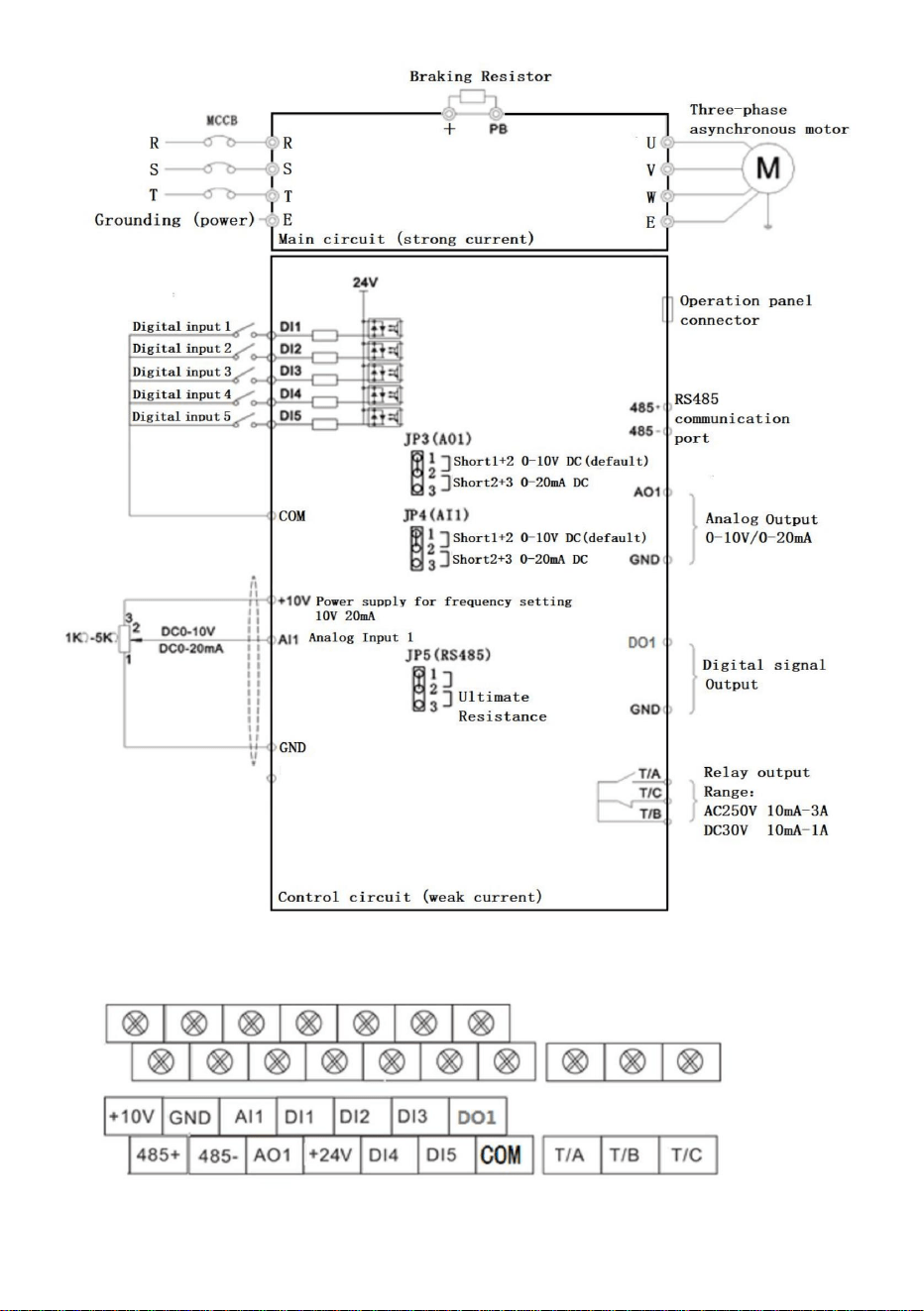
7
Figure131Descriptionduterminaldecommandeduschémadecâblage0,7511,0kW
Machine Translated by Google

Définirlaméthodedesparamètres:
8
Touchedejogging
ARRÊT
Descriptionduvoyantlumineuxdefonction
PRG
▼
Incrémentdescodesdedonnéesoudefonction
clé
RUN:Témoindefonctionnement
Exécutezlaclé
3.Lestouches▲▼etDISPmodifientlesvaleursdesparamètres,latoucheENTERenregistrelesparamètres,
4.Sivousdevezmodifierd'autresparamètres,répétezlesétapes2,3,tellesquelamodification
Toucheverslebas
F/R:Témoindemarcheavantetarrière
Entrezdanslemenuetconfirmezle
ToucheMaj
1.AppuyezsurleboutonPRGpourafficherleP0.00,2.Les
touches▲▼etDISPsélectionnentlenumérodeparamètreàmodifier,etle
A:Témoinlumineuxdecourant
modedefonctionnement
Menuentreousort,avecparamètre
clé
LimitéaucodedefonctionP08.01FAIREDUJOGGING
Nom
Hz:voyantd'affichagedefréquence
Déterminerle
Donnéesdécroissantesoucodesdefonction
Programmation
afficherlecontenu
ToucheStop/ResetOpérationd'arrêt/deréinitialisation,
achèvement,Retouràl'interfacedefréquenceenutilisantlatouchePRG.
Symboledeclé
réglagedesparamètres
G/D:Témoinlumineuxdecontrôledecommunication
▲
COURIR
LatoucheENTRÉEpermetd'accéderauparamètre,
ERR:voyantdedéfaut
modification
Touchesupérieure
AFFICHAGE
ORL
Déclarationdefonction
V:Témoindetension
Sélectionnezlebitmodificateurdeparamètreetle
Démarrerl'onduleursousleclavier
2.Fonctionnementetaffichage
Machine Translated by Google

Tempsd'exécutionrestant
RéglagePID
065535m/min
TensionAI1(V)
0,00320,00Hz(P01.22=2)
P00.22
P00.26
vitesselinéaire
P00.18 0à100kHz
032767
P00.07
P00.25
Vitessederétroaction(Hz)
P00.00
0,00mAà20,00mA
Tensiondujeudebarres(V)
Courantdesortie(A)
AI1Tensionavantcorrection
compterlavaleur
0,000V~10,570V
032767
065535
Puissancedesortie(kW)
Affichagedelavitessedechargement
0,000mAà20,000mA
100,00%100,00%
P00.10AI2Tension(V)oucourant(mA)
Réglerlafréquence
P00.17
P00.06
P00.21
DEl'étatd'entrée
0,0~6500,0Min
Paramètredecommunication
P00.24
Fréquenced'entréed'impulsion
P00.14
P00.03
065535
0V~1140V
Duréedefonctionnementactuelle
P00.16
P00.05
0,00A~655,35A
065535
correction
ÉtapePLC
0,0~6500,0Min
0,00Và10,57V
0,03200,0Hz(P01.22=1)
P00.20
P00.09
3200,0Hz3200,0Hz
200,0%200,0%
P00,Groupedesurveillance
01023
P00.28
P00.13 065535
Tensiondesortie(V)
06500min
P00.02
0,01V
fréquencedefonctionnement
Puissanceactuelleheure
P00.04
065535
P00.08
320,00Hz~320,00Hz
Coupledesortie(%)
P00.15
RétroactionPID
P00.12
P00.01
065535
0,0Và3000,0V
P00.19
AI2Tension/Courantavant
Valeurdelongueur
0,000V~10,570V
ÉtatdesortieDO
3.Tableaurécapitulatifdesparamètresfonctionnels:
9
Machine Translated by Google

10
2:ModèledecontrôleV/F
mode
—paramètrenonmodifiablesousl'étatd'exécution•—
leparamètreréellementdétecté,nonmodifiable
P0059
P00.31
modèle)
P00.42
100,00%100,00%
P01.01
modifier
P0061
Couplecible,(%)
P00.40TensiondesortieduVFséparant
TypeG/P
0V~Tensionnominaledumoteur
P00.44Affichagevisueldel'étatdelafonctionDI2
Affichagedel'étatdel'entréeIN
1.Contrôlemoteur
—paramètremodifiabledansn'importequellecondition
P0060
P00.35
Définirlaplage
2:TypeP(ventilateuretpompeàeau
P01.00
Affichagedel'étatdelafonctionDI1
2
canal(voyants«L/R»éteints)
P01Groupefonctionneldebase
0,00Hz~500,00Hz
P00.39TensioncibledeséparationVF
P01.02
modèle)
P00.41
0,0°à359,9°
commande
FC
Fréquencedefonctionnement(%)
P00.32Affichern'importequellevaleurd'adressemémoire
Contrôle
065535
P00.43
AffichagedelafréquenceX
messaged'erreur
0:commanded'exécutiondupanneaudecommande
valeur
0,00Hz~500,00Hz
FacteurdepuissanceAngle
(Fonction41.Fonction80)
Définirlafréquencede(%)
AffichagedelafréquenceY
0
065535
100,00%100,00%
Affichagedel'étatdel'entréeDO
1:TypeG(chargeàcoupleconstant)
Opération
Usine
nom
(fonction01.fonction40)
Étatdel'onduleur
P00.37
0:vecteursanscapteurdevitesse
1
0V~Tensionnominaledumoteur
P0045
P00.30
Machine Translated by Google

11
1:CanalTerminalRun(voyants«L/
R»allumés)
4
P01.06
P01.04
0:Parrapportàlafréquencemaximale
deP01.101:Par
rapportàlasourcedefréquenceX
Fréquenceprincipale
LimitedeYlorsque
1:Ensemblenumérique(fréquence
prérégléeP01.08,touche▲/▼duclavier,
mémoiredecoupuredecourant)
IdentiqueauréglageP01.03
(SourcedefréquenceprincipaleX)
00
(Feux«L/R»clignotants)
1:Fonctionnementprincipaletsecondaire
9:Ensembledecommunication.
P01.05
P01.03
2:Commandedecommunication
Limiterlasélectionde
0%~150%
ET
Unseulchiffre:Sélectiondelasource
defréquence
sourceX
canal
0
2:ensembleanalogiqueAI1(010
V);3:ensembleanalogiqueAI2(010
Vou20
mA);4:potentiomètrede
panneau;5:ensembled'impulsions(0à50
kHzDI5);6:ensembledevitesseà
plusieursétages7:ensemblePLCsimple;
100%
0:Ensemblenumérique(fréquencepréréglée
P01.08,touche▲/▼duclavier,pertede
puissance)
Sourcede
fréquencesecondaire
Ylorsquesuperposition
defréquence
P01.07Sourcedefréquence
0
canal
8:EnsembledecontrôlePID;
superposition
defréquence
0:SourcedefréquenceprincipaleX
Machine Translated by Google

12
P01.11
Fréquence
limitesupérieure
2:FréquenceprincipaleXet
0:X+Y
V/F:
0:Directioncohérente,1:
50,00
résultats
Fréquence
limitesupérieure
0,00Hz~P01.10
P01.09Sensdemarche
4:LafréquenceYcommuteavec
Fréquence
desprépositions
Hz
fréquenceXetprincipaleet
Hz
Leminimumdesdeux.
P01.08
source
Biaisde
fréquencelimitesupérieure
0,00Hz
1:XY
CommutateurdefréquencesecondaireenY
Hz
50,00Hz
Sensopposé
Fréquencede
sortiemaximale
0
P01.12
Dixchiffres:Relationde
fonctionnementdefréquencedeXetY
résultats(larelationd'opérationest
déterminéepardixchiffres)
0,00Hz~Fréquencemaximale
P01.10
Fonctionnementprincipaletsecondaire
Vecteur:50,00Hz~500,00Hz
0:P01.12Configuration1:
AI1Configuration
2:Al2Configuration
3:AI3Configuration
4:Réglagedesimpulsions(050KHZDI5);5:
Configurationdelacommunication
P01.14P01.10
Résultatsdel'opérationsecondaire
3:
50,00
0
P01.10
P01.13
3:Basculerentrelemodeprincipal
2:MaximumdesDeux,
2000,00Hz
50,00
Machine Translated by Google

13
0,00Hz
Référence
P01.15Fréquenceporteuse
Tempsdedécélération
0
Tempsd'accélération
2:0,01seconde
Sélectiondugroupede
paramètresdumoteur
Éteindre
0
Unitédetempsde
Pourlemodèle
1
0:Groupedeparamètresmoteur1,
1:Groupedeparamètresmoteur2.
0,0s6500,0sP01.19=1
Fréquencedepolarisation
delafréquenceY
lorsque
0:Non,1:Oui
tempsdedécélération
P01.21
0
1
Fréquence
Accélérationet
P01.14
Réglagedefréquence
numérique
1:Réglagedelafréquence
0:Pasdemémoire1:Mémoire
1
1
Duréed'exécution
P01.19
2
Ajusteravec
latempérature
mémoirepour
0:Fréquencedefonctionnement,
P01.16
1:0,1seconde
fréquencede
FréquencederéférenceP01.25
Résolutionde
0,00Hz
HAUT/BAS
P01.23
P01.17
fréquence
0s~65000s(P01.19=0)
tempsdedécélération
Fréquenceporteuse
secondes
commandes.
superposition
P01.18
0,00Hz~P01.12
Accélérationet
P01.22
0
instruction
defréquence
0,00s~650,00s(P01.19=2)
0:FréquencemaximaleP01.101:
Fréquencederéglage
2:100Hz
Résolutiondetouteslesfréquences
P01.25
0,5kHzà16,0kHz
0:1
P01.26
Pourlemodèle
0,00Hz~Fréquencede
sortiemaximaleP01.10
P01.24
Limiteinférieure
Machine Translated by Google

14
Modèle
Onduleur
Chiffreunique:fréquencedeliaisondes
commandesdupanneaudecommande
groupé
Typedemoteur
sélection
Millechiffres:exécuterautomatiquement
lasourcedefréquencedeliaison
7:APIsimple
0,1A~6553,5A
Courantnominalde
0
5:Ensembled'impulsions(050KHZDI5);
P01.27
0,01A~655,35A
1:Ensemblenumérique
P02.01
9:Ensembledecommunication
0:Moteurasynchroneordinaire,
Dela
P02.02
P02.03
sourcedefréquence
sélectiondelasource
sélection
Puissancenominalede
100chiffres:sélectiondela
sourcedefréquencedeliaisonde
commandedecommunication
Tensionnominalede
au
(Puissancedel'onduleur>55kW)
Sourcedecommande
référence
Dixchiffres:sourcedefréquencede
liaisondecommandedeterminal
6:Vitessemultisegments;
P02.00
Selon
(Puissancedel'onduleur<=55kW)
2:AI13:AI24:AI3
0000
1Và2000V
1:Moteurasynchroneà
fréquencevariable
0,1kWà400,0kW
Moteur
Groupedeparamètres1dumoteurasynchroneP02
0:Aucuneliaison
8:PID
moteur
Moteur
Machine Translated by Google

15
P02.10
dumoteur
0,001Ω65,535Ω(Puissancede
l'onduleur<=55
kW)0,0001Ω6,5535Ω(Puissancede
l'onduleur>55kW)
0,001Ω65,535Ω(Puissancede
l'onduleur<=55
kW)0,0001Ω6,5535Ω(Puissancede
l'onduleur>55kW)
0,01mH655,35mH
P02.08
Résistanceauxfuites
P02.05
(Puissance
del'onduleur>55kW)
0:pasde
fonctionnement1:Réglagelorsquele
moteurestàl'arrêt12:Réglage
dynamiquedumoteur3:Réglagelorsque
lemoteurestcomplètementàl'arrêt2
Bouclede
vitesseproportionnelle1
1à100
P02.04
Résistancedurotor
(Puissancedel'onduleur>55kW)
0
0,01Hz~Fréquencede
sortiemaximaleP01.10
dumoteur
0,001Mh65,535mH
lemoteur
0,1A~P02.03
30
Résistancedustator
Vitessenominalede
dumoteur
(Puissancedel'onduleur>
55kW)0,1mH6553,5mH(Puissance
del'onduleur<=55kW)
P02.07
P02.09
Courantàvidede
P03.00
1tr/min~65535tr/min
Fréquencenominale
dumoteur
Paramètre
0,01AP02.03(Puissancede
l'onduleur<=55kW)
P03Paramètresdecontrôlevectorieldugroupemoteur1
P02.37Sélectionderéglage
Réglage
0,01mH655,35mH
(Puissancedel'onduleur<=55kW)
moteur
P02.06
Résistancemutuelle
dumoteur
Machine Translated by Google

16
4:Réglaged'impulsions(DI5);
P03.14
0,50s
P03.05
20
constantes
Gainproportionnel
de
0
P03.15Gainproportionnel
100%
5,00Hz
Tempsd'intégration
delaboucledevitesse2
excitation
0,01sà10,00s
contrôledevitesse
1à100
0,000s~0,100s
3:AI3;
Gainintégral
d'excitation
50%200%
7:MAX(AI1,AI2)
règlement
0,00P03.05
modedecontrôle
060000
P03.04
sourcesous
Tempsde
filtrageducoupleSVC
150,0%
Bouclede
vitesseproportionnelle2
0,0%200,0%
Fréquencedecommutation
P03.07
1300
Contrôlevectorielde
6:MIN(AI1,AI2)
0,01sà10,00s
Limitesupérieuredecouple
P03.13
1,00s
Fréquencedecommutation
10,00Hz
060000
1
legaindedécalage
Limitesupérieurede
couplesousrégime
5:Cadredecommunication;
2
P03.01
0,050s
P03.10
0:P03.10réglage
1:AI1;2:AI2;
2000
P03.03
060000
P03.09
2000
P03.02
P03.06
P03.02Fréquencedesortie
maximaleP01.10
mode
règlement
Tempsd'intégration
delaboucledevitesse1
Machine Translated by Google

17
régulationducouple
4:Courbedecoupledécroissante2
(puissance1,4)
0,00Hz
Réglagede
l'amplificationde
couplePoint
decoupurede
l'amplificationde
couple
FréquenceV/F
multipoint
1TensionV/F
multipoint1FréquenceV/Fmultipoint2TensionV/Fmultipoint2
P04.01
1:CourbemultipointV/F
2:Courbedecoupledécroissante
1(Courbecarrée)
0,0%
P04.03
ParamètresdecontrôleV/FP04
P04.00RéglagedelacourbeVF
P04.06
P03.16
0,00Hz
10:Modedeséparationcomplète
VF
50,00Hz
6:Courbedecoupledécroissante2
(puissance1,6)
Gainintégralde
larégulationdecouple
0,1%à30,0%
0,0%
Parmodèle
0,0%100,0%
3:Courbedecoupledécroissante2
(puissance1,2)
de
11:ModesemiséparationVF0,0
%(coupledelevageautomatique);
0:courbelinéaireV/F
0,00Hz~P04.05
0,0%100,0%
060000
0
P04.02
P04.05
0,00Hz~Fréquencede
sortiemaximaleP01.10
1300
8:Courbedecoupledécroissante2
(puissance1,8)
P04.04
P04.03P04.07
Machine Translated by Google

P04.14
0,0s1000,0s
P04.05Puissancenominaledumoteur
0,0%200,0%
4:Réglagedel'impulsion(DI5)
64
0200
0,0%
Tensionpourla
séparationVF
tensionnominaledu
moteur.0,0s~1000,0s
0,0s
P04.17
2AI2
P04.08
gaindesuppression
7:LePID
0,0s
Chutedetensionà
018
0
P04.07
0
Oscillation
0:ParamètresnumériquesP04.14
0V~Tensionnominaledumoteur
Remarque:heureàlaquelle0Vmonteà
P04.16
0:Lafréquenceetlatension
chutentà0séparément;
V/Fterminé
fréquenceP02.04
0100
5:Instructionmultiple
P04.10
Sourcedetensionpar
Tempsdemontéeen
tensiondelaséparationVF
Tempsdechutede
tensiondelaséparationVF
P04.09
FréquenceV/F
multipoint
3TensionV/F
multipoint3
ContrôleV/F
Compensation
defréquencedeglissement
pourV/F
0,0%100,0%
3AI3
8:paramètredecommunication
Remarque:100,0%,correspondantà
latensionnominaledumoteur
P04.15
Moded'arrêt
deséparationVF
0,0%
P04.11
0V
1:AI1
P04.13
Remarque:Tempspendantlequellatension
nominaledumoteurtombeà0V
1:Lafréquencechuteaprèsla
Parmodèle
0,00Hz
gaind'excitation
6:APIsimpleVFséparé
Machine Translated by Google

19
Élévationmaximale
5:Contrôledemarchearrière(RJOG)
courantd'action
décrochageactuel
20
1
BorneDI1
5Hz
Actiondedécrochageen
casdesurtension
Tensiondesuppression
dudécrochageencasde
surtensionGainde
fréquencede
suppressiondudécrochage
encasdesurtension
Gaindetensionde
suppressiondudécrochageencasdesurtension
150%
1
Compensation
30
Gaindela
suppressiondeOver
P04.23
0100
3:commandedemarcheàtroisfils4:
commandedemarcheavantparàcoups(FJOG)
50%
0à50Hz
Décrochageparsurintensité
2:Marchearrière(REV)ou
P05.00
décrochageactuel
0100
650,0V800,0V
0:Aucunefonction;
1:Activer.
Encoursd'exécution;
1
1:Activer.
50%200%
Décrochageencasdesurtension
P04.19
P04.24
0100
P04.18
actionterminée
0:Désactiver,
P04.22
GroupeP05,Paramètresd'entrée
limitedefréquencepour
P04.21
Suppressionde
0:Désactiver,
1:Marcheavant(FWD)ou
30
fonction
P04.20
P04.26
50%200%
760,0V
coefficientde
P04.25
Interrupteurmarcheavant/arrière
Décrochageparsurintensité
Machine Translated by Google

20
9:Entréedesignalderéinitialisation
externe(RST)
21:InterdictionVFDACC/DEC
24:Pausedefréquencedupendule
32:FreinageCCimmédiat;
8:Contrôled'arrêtgratuit
23:Réinitialisationdel'étatdel'automate
17:Sélectiondel'heureACC/DEC2(TT2)
25:Entréeducompteur
26:Réinitialisationducompteur
10:Suspendrelefonctionnement;
11:Entréenormalementouverte(NO)dedéfaut
externe12:
Multivitesse113:Multi
vitesse214:Multivitesse3
15:Multivitesse416:
SélectiondetempsACC/DEC
1(TT1)
20:CommutateurdecommandeExécuter
31:Réservé;
18:Commutateurdesourcedefréquence
19:HAUT/BASRemiseàzérodela
fréquence(borne,clavier)
27:Entréedecomptagede
longueur28:Réinitialisation
delongueur29:Désactivationducontrôle
decouple30:Réglagedesimpulsions(seulDI5
peuteffectuerleréglage,P05.04=30)
7:Diminutiondefréquence(Terminal
DOWN)
22:PauseducontrôlePID
33:Entréededéfautexterne(normalement
6:Augmentationdefréquence(borneUP)
terminal1
Machine Translated by Google

21
P05.04
34:Modificationdefréquence
41:Bornedesélectiondumoteur1
BorneDI4
49:FreinageCClent
51:Commandeàdeuxfils/Commandeàtroisfils
39:LafréquenceXcommuteavec
lafréquenceprédéfinie
12
BorneDI3
terminal2
47:Arrêtd'urgence
9
36:Terminaldestationnementextérieur1
4
45:Erreurdéfinieparl'utilisateur2
BorneDI2
13
43:LecommutateurdeparamètresPID
Permet
interrupteurdecommande
fonctionnel
50:Tempsd’exécutioneffacé;
fonction
P05.03
40:LafréquenceYchangeavec
lafréquencepréréglée
fermé(NC)
48:Parkingextérieurterminal2
38:PauseintégralePID;
fonctionnel
P05.02
37:Commutateurdecommanded'exécution
46:Interrupteurdecontrôlede
vitesse/decouple
fonctionnel
P05.01
52:Désactivationdel’inversion;
35:signald'entréePIDinversé;
44:Défautdéfiniparl'utilisateur1
BorneDI5
(seulDI5peut
Machine Translated by Google

22
100,0%+100,0%
valeurdelacourbeAI
P05.10TempsdefiltrageDI
courbe1
Fréquence
P05.13+10,00V
Correspondant
P05.17
10,00V
Correspondant
2:Modedecontrôleàtroisfils1,
Mode
Entréemin.2
0,001Hz/s65,535Hz/s
P05.16
P05.11
courbe1
100,0%
Correspondant
0,00V~P05.15
0,10s
P05.18+10,00V
1:Modedecontrôleàdeuxfils2,
saisir
valeurdelacourbeAI
P05.12
Correspondant
100,0%+100,0%
0,0%
P05.18
Contrôledesterminaux
0,00V
0
1Entréemin.
Entréemax.del'IA
100,0%+100,0%
P05.13
temps
0:Modedecontrôleàdeuxfils1,
P05.15
P05.19
1,00Hz/s
fonction,
P05.04=30)
Entréeminimaledel'IA
P05.21
0,010s
valeurdelacourbeAI
CourbeAI2'sMin.
Courbed'entrée
AImax.1filtrage
0,00V
0,000s~1,000s
100,0%+100,0%
0,00V~P05.20
10,00V
0,0%
étapederéglage
Entréemax.2's
0,00sà10,00s
100,0%
3:Modedecontrôleàtroisfils2.
P05.14
taille
valeurdelacourbeAI
P05.20Entréemax.deAI2
réglagedupouls
Machine Translated by Google

23
valeurdePulse
1:j’ai1pute
temps
Correspondant
P05.24
P05.28
valeurdePulse
P05.23+10.00V
(14h,voirP05.18~P05.21.)
100,0%+100,0%
10,00V
Correspondant
P05.32
P05.25
Correspondant
0,0%
Valeurminimalede
P05.29
Bitunique:sélectiondelacourbeAI1
P05.26
100,0%+100,0%
2:j'ai2putes
0,00sà10,00s
P05.31
temps
10,00V
Entréed'impulsion
P05.33SélectiondelacourbeAI
P05.27
Entréed'impulsion
saisir
100,0%
valeurdelacourbeAI
temps
(14h00,voirP05.13~P05.16.)
Courbed'entrée
AImax.3filtrages
Valeurmax.de
0,10s
0,00V
Entréemax.
Filtragedesimpulsions
3'sEntréemin.
Entréemax.del'IA
P05.22
courbe3
321
10,00V~P05,25
0,10s
P05.30
Entréemin.
valeurdelacourbeAI
CourbeAI3'sMin.
0,00sà10,00s
Correspondant
10,00V~P05,25
100,0%+100,0%
(14h00,voirP05.23~P05.26.)
100,0%+100,0%
0,10s
10,00V
3:j'ai3putes
P05.23
100,0%
P05.23+10.00V
0,0%
0,00sà10,00s
CourbeAI2filtrage
Machine Translated by Google

24
niveauefficace
Bitunique:DI6,
(16h,voirP24.00P24.07)
L'IAestendessous
BorneDI1DI5
P05.35DélaideDI1
P05.37DélaideDI3
Dixbits:AI2endessousduréglage
d'entrée
minimum(identiqueaubitunique1~2)
0:Niveauefficaceélevé,1:Faible
P05.39
0,0s~3600,0s
(lemêmequecidessus)
P05.34
Dixmillebits:DI5
P05.38
Dixbits:sélectiondelacourbeAI2
(identiqueàcelledubitunique1à5)
Descentainesdebits:DI3;
sélection
0,0s~3600,0s
sélectiondumode
leminimum
5:j'aidesputes4
0,0s~3600,0s
valide
P05.36DélaideDI2
Bitunique:DI1;
valide
Centbits:AI3endessousduréglage
d'entrée
minimum(lemêmequecidessus)
4:j'ai4putes
0,0s
Bitunique:AI1endessousduréglage
d'entrée
minimum0:Valeurcorrespondantede
l'entrée
minimum1:0,0%
0:niveauefficaceélevé,1:niveau
efficacefaible
BorneDI6D17
00000
Centbits:sélectiondecourbeAI3
000
00000
0,0s
Millebits:DI4,
0,0s
(16h,voirP24.08P24.15)
réglaged'entrée
sélectiondumode
Dixbits:DI2;
Machine Translated by Google

GroupeP06,Paramètresdesortie
0
13:Limitationdefréquence
11:LecyclePLCestterminé
Relais
5:Fonctionnementàvitesse
nulleduVFD(enfonctionnement)
Sélection
3:Signaldedétectiondeniveaude
fréquence1(P14T1)
9:Lenombrespécifiéestatteint
19:Sortieétatsouspression20:Paramètre
decommunication21:Localisation
complète(réservée)25
sélectiondefonction
limite
8:Ledécomptedessetsarrive
P06.02
7:Surchargedel'onduleur
SortieDO1
(TATBTC)
14:Limitationdecouple
12:Tempsdefonctionnementaccumulé
16:AI1>AI2
6:Alerteprécocedesurchargedumoteur
Dixbits:DI7
10:Lalongueurestatteinte
4:Indicateurd'arrivée
defréquence(FAR)
arrive
0:Aucunesortie
1:Indicateurde
fonctionnement;2:Sortiededéfaut(pour
défautd'arrêtlibre)
Panneaudecontrôle
Fonction
18:Lafréquencedesortieatteintlalimite
inférieure(lorsdel'exécution)
2
P06.01
Alerteprécoce
15:Prêtàcourir
17:Lafréquencedesortieatteintlalimitesupérieure
Machine Translated by Google

26
arrive
39:Surchauffedumoteur
Préalerte40:
Cetempsdefonctionnementarrive
41:Sortiededéfaut(pourlibre
0:Fréquencedefonctionnement,
1:Fréquencedéfinie.
0
24:Tempsdemisesoustensionaccumulé
pressiondesortie)
26:Fréquencedesortie1atteinte27:
Fréquencedesortie2atteinte28:
Courantdesortie1atteint29:Courantde
sortie2atteint30:Atteintrégulièrement31:
Dépassementdusignald'entrée
Al132:Chutedecharge33:
Fonctionnementinversedu
VFD34:Étatdecourantnul
2:Courantdesortie,
3:Coupledesortie,
4:Puissancede
sortie,5:Tensiondesortie,
Sélectionde
lafonctiondesortieAO1
25:Signaldedétectiondeniveaude
fréquence2(P14T2)
latempératurearrive
36:Courantdesortiehorslimite
37:Fréq.desortieatteintlalimite
inférieure(arrêtégalementsortie)
P06.07
35:Lemoduled'alimentation
Sélectiondela
fonctiondesortieAO2
23:Fonctionnementàvitessenulle2
(égalementensortielorsdel'arrêt)
défautd'arrêtetpasdesous
P06.08
1
22:Proximitédel'emplacement(réservé)
38:Sortiededéfaut(touslesdéfauts)
Machine Translated by Google

27
0,0s
Dixbits:RELAY1
8AI2
AO2àpolarisationnulle
parrapportàlapuissancedumoteur)
10,00+10,00
0,0s~3600,0s
SortieRELAY2
P06.17
12:Réglagedelacommunication,
13:Vitessedumoteur
(Correspondantà1000,0V)
sélectiondestatut
AO1àpolarisationnulle
P06.13
(Pourcentagedelavaleurréelle
P06.11
1,00
P06.22
DélaidesortieDO
tempsderetard
11:Valeurdecomptage
P06.19
SortieDOvalide
parrapportàlapuissancenominaleduVFD)
0,0%
P06.10
P06.18
15:Tensiondesortie(100,0%
0,0s
16:Coupledesortiedumoteur
1,00
GainAO2
SortieRELAIS
10:Longueur
100,0%+100,0%
Bitunique:DO
(Pourcentagedelavaleurréelle
7AI1
GainAO1
Correspondantà1000,0A)
0,0%
0,0s
0,0s~3600,0s
coefficient
9AI3
100,0%+100,0%
0,0s~3600,0s
P06.12
0:Logiquepositive,1:Antilogique
17:Coupledesortieduvariateurdefréquence
tempsderetard
14:Courantdesortie.(100,0%
temps
coefficient
10,00+10,00
00000
6:Fréquenced'impulsiond'entrée
Machine Translated by Google

28
Accélération
30,0%
0:Démarragedirect
0,00Hz
P07.01
0%
segmentenS
2:CourbeSModeAcc/DecB
CourantdefreinageCC
P07.00Modededémarrage
Suividevitesse
segmentenS
Suividelavitesse
delavitesse
P07.06
0
0%~100%
démarrer
30,0%
tempsdemaintien
1:CourbeSModeAcc/DecA
0
P07.08
P07.09
1à100
0,0s
0,0s
Mode
décélération
1:Commencezparla
fréquencedetravail
0,0%100,0%P07.09
méthode
0,0s100,0s
Fréquencededémarrage
0:modeAcc/Declinéaire
2:freinageCC+démarrageàlafréquence
dedémarrage
TempsdefreinageCCà
Rapportdetempsdedémarrage
fréquence
GroupeP07,Paramètresdecontrôlededémarrageetd'arrêt
P07.02
fréquence
0,00Hz~10,00Hz
P07.07
et
P07.03Fréquencededémarrage
1:Commencezparsuivrelavitesse
P07.04
Rapportdetempsdedémarrage
audémarrage
courbe
2:Commenceraumaximum
courbe
0
0:Commencerparl'arrêt
P07.05
20
0,0s~100,0s
0,0%100,0%P07.08
CentBits:RELAY2
Machine Translated by Google

29
P08.01FonctiondelatoucheM
P08.03
P01.10
arrêt
0,0s
valide
4:RJOG(Contrôledemarchearrière)
actuel
Fréquence
temps
Bit00:Fréquencedefonctionnement1(Hz)
P07.13CourantdefreinageCC
0:LatoucheMn'estpasvalide
P07.11
P07.15
Contrôle(contrôledu
terminaloudelacommunication)
etcontrôledupanneaudecommande,
lorsqueP01.02=1ou2
Bit02:Tensiondubus(V)
Suividevitesse
3:FJOG(commandedemarcheavant)
Moded'arrêt
1
Étatdefonctionnement
0%
Claviersdegroupeetparamètresd'affichageP08
0,0s100,0s
ARRÊT/RÉINITIALISATION
RetarddefreinageCC
P08.02
0,00Hz
100%
tauxd'utilisation
2:Interrupteurmarcheavant/arrière
P07.10
30%200%
AffichageLED
paramètre1in
0,0s100,0s
0,00Hz~Fréquencemaximale
TempsdefreinageCCà
frein
P07.14
1:LatoucheSTOP/RESToujours
0
Freinàcourantcontinu
0
0%100%
fonctionclé
P07.18
0000FFFF
P07.12
1F
0:LatoucheSTOP/RESn'estvalablequ'en
modedecontrôledupanneau
seuildeDC
0,0s
0%100%
1:Basculerentrelatélécommande
Bit01:Réglagedelafréquence(Hz)
0:Ralentissezpourarrêter1:Ralentissezpour
arrêter
Machine Translated by Google

30
Bit04:Courantdesortie(A)
Bit13:valeurdelongueur
AffichageLED
paramètre2in
Bit03:Fréquencedefonctionnement2(Hz)
Bit05:AI1tensionavantcorrigée
Bit11:TensionAI3(V)
Bit12:Paramètresdecommunication
(V)
Bit09:TensionAI1(V)
Bit01:étapePLC
Bit11:PULSEFréquenced'entrée
Bit07:étatdel'entréeDI
(Heure)
0000FFFF
(V)
Bit14:Affichagedelavitessedechargement
Bit05:Puissancedesortie(kW)
(V)
Étatdefonctionnement
Bit04:Tempsd'exécutionrestant
P08.04
Valeur
Bit12:valeurdecomptage
Bit03:Tensiondesortie(V)
Bit02:PULSEFréquenced'entrée
(kHz)
Bit10:TensionAI2(V)
Bit08:Vitessedelaligne
(Hz)
Bit08:étatdesortieDO
Bit00:RétroactionPID
Bit07:AI3tensionavantcorrigée
Bit10:Duréed'exécutionactuelle(min)
Bit06:AI2tensionavantcorrigée
Bit06:Coupledesortie(%)
Bit15:ParamètresPID
0
Bit09:Puissanceactuelleetheure
Machine Translated by Google

31
P08.07
•
(Hz)
Bit03:étatdesortieDO
Vitessedechargement
Bit10:Vitessedechargement
Bit12:PULSEFréquenced'entrée
Bit01:Tensiondubus(V)
Duréedefonctionnement
P08.09
•
P09.01
33
0000FFFF
Bit08:Valeurdelongueur
P08.08Numérodeproduit
P09.00Fréquencedejogging
0,0s~6500,0s
Bit15:FréquencesecondaireY
Moduledepuissance
Bit06:tensionAI3(V)
paramètredansStop
0,0100,0
P01.10
Bit04:TensionAI1(V)
Bit14:AffichagedelafréquenceprincipaleX
(kHz)
facteurd'affichage
Bit11:ParamètresPID
P08.06
GroupeP09,fonctionauxiliaire
0h~65535h
Bit02:étatdel'entréeDI
Bit13:Vitessederétroactionducodeur
Bit09:étapePLC
Bit00:Réglerlafréquence(Hz)
P08.05
Cumulatif
20,0s
Tempsd'accélérationdujogging
Affichage(Hz)
Bit07:Valeurdecomptage
•
statut
température
0,00Hz~Fréquencemaximale
2,00Hz
ÉcransLED
(Hz)
Bit05:TensionAI2(V)
1,0000
0,00016,5000
Machine Translated by Google

32
0h
P09.13
0,4~4,0kW
Tempsd'accélération
fréq.
2
Mortinversée
0,0s
0:fonctionneràunefréquencelimiteinférieure
P09.08
15.0S
Tempsdedécélération
Interdire
0,00Hz~10,00Hz
Tempsdedécélération
P09.02
P09.04
Positifet
puissancecumulée
0
Tempsdedécélération
Lorsqueleréglage
5,5~30,0kW
0,01Hz
lalimiteinférieurede
0:Autorisé;
P09.15
3
20,0s
àl'heured'arrivée
2:fonctionnementàvitessenulle
P09.10Fréquencedesaut2
P01.10
37,0132,0kW40,0S
P09.11
P09.14
160,0à630,0kW60,0S
gamme
autorisation
0h~65000h
4
Tempsd'accélération
0,00Hz
Inverse
0,0s3000,0s
P09.05
Heurededécembredujogging
3
1:Arrêter
2
P09.09Fréquencedesaut1
0,00Hz~Fréquencemaximale
15.0
P09.07
7,5S
Fréquencedesaut
0,00Hz
temps
P09.12
0
Tempsd'accélération
fréquence
P09.16
0,00Hz
lafréquenceestinférieureà
P09.03
4
Contrôledeschutes
Paramètre
P09.06
1:
Duréerecommandée:
Machine Translated by Google

33
P09.26
valeurdedétection2
0h
0,0%~100,0%(niveauP14T1)
P09.30
50,00
0:nonvalide,1:valide
0
P01.10
Fréquence
d'arrivéearbitraire
P09.21
0:Nonprotégé;
valeurdedétection1
Hz
Valeurde
décalagede
détectiondefréquence(P14T1)
tempsd'accélération
P01.10
P09.22
Fréquencedecommutationde
P09.28
0,0%
0,00Hz~Fréquencemaximale
Valeurde
décalagede
détectiondefréquence(P14T2)
arrivéeenmarche
P09.18Protectiondedémarrage
Fréquence
50,00
(P14T1)
P09.25
5,0%
Fonctionde
sautdefréquence
0,00Hz
P09.19
Prioritédu
terminalJog
Hz
0,00Hz~Fréquencemaximale
0
(P14T2)
0,0%~100,0%(fréquence
maximale)
1etletemps2
0h~65000h
Fréquencedecommutationde
0:nonvalide,1:valide
cumulatif
P09.20
0,0%~100,0%(niveauP14T2)
Fréquence
largeurdétectée
P01.10
tempsdedécélération
5,0%
P09.17
PendantAccet
0,00Hz
Déc.
P09.27
50,00
Hz
0,00Hz~Fréquencemaximale
0,00Hz~Fréquencemaximale
P09.29
0
atteintle
0,00Hz~Fréquencemaximale
Fréquence
1etletemps2
Paramètre
Machine Translated by Google

34
P09.37
0,0%
0,0%~100,0%(fréquence
maximale)
5,0%
0,0%~100,0%(fréquence
maximale)
0,0%(nondétecté)
Arrivéearbitraire
0,0%~300,0%(courantnominal
dumoteur)
0,0%
Détectiondecourant
50,00
0,00Hz~Fréquencemaximale
Fonctionminuterie
0,0%300,0%
Tempsderetardde
Fréquence
d'arrivéearbitraire
0,01sà600,00s
0,00s
P09.39
Tempsderetardde
Courantd'arrivée
arbitraire1
0,0%~300,0%(courantnominal
dumoteur)
Fréquence
d'arrivéearbitraire
largeuractuelle1
0:réglageP09.44,
largeuractuelle2
largeurdétectée2
P09.36
P09.42
actuel
100,0%
P09.32
Arrivéearbitraire
P09.43Duréed'exécutionduminuteur
valeurdedétection2
P09.35
P09.40
100,0%correspondaucourant
nominaldumoteur
Détectionactuelle
P09.31
200,0%
Arrivéearbitraire
0,0%
Fréquenced'arrivée
arbitraire
détectéelargeur1
niveaudedétection
0
sortiesur
0,0%~300,0%(courantnominal
dumoteur)
0,00s~600,00s
P09.34
0,0%
0,10s
P09.38
0,1%~300,0%(courantnominal
dumoteur)
courant2
0:nonvalide,1:valide
P09.33
100,0%
0,0%~300,0%(courantnominal
dumoteur)
P09.41
Hz
Valeuractuellede
0
Courantnul
Sortieterminée
sélection
valeurdedétection1
Machine Translated by Google

35
0,00Hz~Fréquencederéveil
P09.49
0,00Hz
1:AI1
Valeurdelimiteinférieure
deprotectiondela
tensiond'entréeAI1
P09.48
P09.4510.00V
75
0,0Min~6500,0Min
0,0s~6500,0s
opération
P09.54
0,00%200,0%
contrôle
temps
6,80V
0,0s
Heured'arrivéedece
0.0Min
Laplaged'entréeanalogique
correspondauP09.44
0,00Hz
0,00V~P09,46
1:Toujoursenmarchelorsquel'alimentation
P09.51Fréquencedusommeil
0,0s~6500,0s
delapuissancedesortie
0,0s
3,10V
2:AI2
P09.47
sur;
0100
Retardderéveil
temps
Facteurdecorrection
0.0Min
sélection
P09.46
P09.44
0
P09.50
P09.53
100,0%
Minuterieenmarche
Valeurlimitesupérieure
deprotectiondela
tensiond'entrée
AI1Protection
contrelasurchauffeValeur
P09.52Délaidemiseenveille
Ventilateurderefroidissement
P09.49
GroupeP10Défautetprotection
0,0~6500,0Min
0:ventilateurenmarchependantle
fonctionnementduVDF
3:AI3
P09.45
Fréquence
deréveil
Fréquenced'hibernation(P09.51)~
FréquencemaximaleP01.10
Machine Translated by Google

36
020
11
Surchargedumoteur
1:Activer
taper
80%
réinitialiser
0:Désactiver,
1:Action
0:Pasdefaute
Unitédefreinage
P10.00
0,2010,00
TenBit:protectioncontreledéclenchementdu
relaisdepuissance
Courtcircuità
690V
Surchargedumoteur
défautautomatique
650,0V800,0V
P10.12
1
0:Aucuneaction
1:Activer
Bitunique:protectioncontrelapertede
phased'entrée
Premieréchec
Protectioncontreledéclenchement
durelaisdepuissance
facteur
réinitialiser
tempsderéinitialisation
1,0s
P10.01
0,1sà100,0s
1
gaindeprotection
sélectionpendant
0:Désactiver,
protectiondeterrelors
delamisesoustension
P10.09
1:Activer
•
Défautautomatique
Protectioncontrelaperte
dephased'entrée/
alerteprécoce
protection
0:Désactiver,
Protectioncontrela
pertedephasedesortie
1,00
Défautautomatique
P10.10
0
P10.07
0:Désactiver,
Agir
P10.11
Intervallepour
1:Activer
P10.13
P10.02
1:Activer
0
1:(Réservé)
1
tensiondedémarrage
P10.14
50100%
P10.08
0:Désactiver,
Surchargedumoteur
Machine Translated by Google

37
31:Leretourd'informationPIDd'exécutionestperdu
41:Commutezlemoteurpendantle
fonctionnement
taper
6:Surtensiondansleprocessusdedéc.
18:Détectiondecourantanormal
13:Pertedephasedesortie
15:Défautexterne
vitesse
29:L'heuredelamisesoustensionarrive
•
•
11:Surchargedumoteur
27:Erreurpersonnaliséedel'utilisateur1
4:Surintensitéenconstante
23:Courtcircuitdumoteuràlaterre
9:Soustension
Troisièmetype
dedéfaut(leplusrécent)
40:Délaid'expirationdelalimitededébitrapide
42:L'écartdevitesseesttropimportant
7:Surtensionàvitesseconstante
2:SurintensitédansleprocessusAcc
16:Exceptiondecommunication
19:Leréglagedumoteurestanormal
14:Lemoduled'alimentationestsurchauffé
exception
30:Chutedecharge
5:SurtensiondansleprocessusAcc
Deuxièmeéchec
12:Pertedephased'entrée
28:Erreurpersonnaliséedel'utilisateur2
P10.15
10:Surchargeduvariateurdefréquence
P10.16
26:Arrivéeàl'heured'exécution
17:Lerelaisdepuissanceestanormal
3:Surintensitédansleprocessusdedéc.
8:Surchargedelarésistancetampon
21:Lectureetécrituredesparamètres
22:Autrematérielanormal
Machine Translated by Google

38
Actuelàla
(leplusrécent)
Tempsdemisesoustensionpour
troisième
échec(leplusrécent)
P10.23
deuxièmeéchec
(leplusrécent)
Borned'entrée
P10.21
échec
•
statutautroisième
Actuelàla
P10.24
statutautroisième
Tensiondubusau
troisième
défaut(leplusrécent)
Duréed'exécutiondu
•
(leplusrécent)
deuxièmeéchec
Bornedesortie
•
•
•
Fréquenceàla
troisième
panne(laplusrécente)
P10.20
•
troisième
défaut(leplusrécent)
L'onduleur
•
•
échec
P10.17
P10.22
•
Fréquenceàla
P10.19
letroisième(le
plusrécent)échec
P10.28
P10.18
échec
statutautroisième
•
P10.27
43:Survitessedumoteur
Machine Translated by Google

39
P10.43
Borned'entrée
deuxièmefaute
premieréchec
P10.33
P10.31
•
•
•
Bornedesortie
statutàla
•
P10.42
deuxièmeéchec
P10.32
Tempsdemisesoustensionpour
Tempsdemisesoustensionpour
échec
échec
deuxièmeéchec
•
P10.39
statutaupremier
P10.34
Étatduterminalde
sortieaupremier
P10.30
•
L'onduleur
•
•
deuxièmeéchec
statutaupremier
•
P10.38
statutpourle
L'onduleur
Tensiondubusàla
premièrepanne
Duréed'exécutiondu
P10.29
P10.37
deuxièmeéchec
•
Courantaupremier
Borned'entrée
P10.44Duréed'exécutiondu
•
•
P10.41
ledeuxièmeéchec
P10.40
lepremieréchec
statutàla
échec
échec
Fréquenceàla
•
Tensiondubusàla
•
Machine Translated by Google

40
Bitunique:surchargedumoteur(Err11)
sélection1
(Err28)
action
Exceptiond'écriture(Err21)
Protectioncontrelespannes
P10.49
0:Arrêtenrouelibre;
1:ModearrêtpararrêtP07.10Bit
unique:Défautpersonnaliséde
l'utilisateur1(Err27)
(Err15)
Dixbits:paramètreluet
0:Arrêtenroue
libre;1:ArrêtenmodeStopP07.10
2:Sautà7%delafréquencenominale
dumoteuretmaintiendu
fonctionnement,retouràlafréquencedéfinielorsque
(Err13)
arrive(Err29)
Exceptiondecommunication
(Err16)
P10.48
00000
Dixbits:pertedephased'entrée(Err12)
Dixmillebits:duréed'exécution
HundredBit:Tempsdemisesoustension
sélection2
action
action
premieréchec
Protectioncontrelespannes
Dixmillebits:
Dixbits:erreurpersonnaliséedel'utilisateur2
00000
Millebits:Défautexterne
0:Routejusqu'à
l'arrêt;1:Modearrêtpararrêt
P07.102:
Continueràcourir;Unseulbit/Centbits/
Millebits:(Réservé)
arrivée(Err26)
Millebits:chutedecharge(Err30)
00000
Centbits:pertedephasedesortie,
P10.47
Protectioncontrelespannes
sélection3
Machine Translated by Google

41
Dixmillebits:rétroactionPID
P10.50
LaPause
fréquence
Puissanceinstantanée
sansinterruption
Sélectiondel'actionde
protectioncontrelesdéfauts4
0,00sà100,00s
0
Millebits:erreurderetourde
vitesse(Err52)
Réserveanormale
90,0%
Dixbits:survitessedumoteur
(Err43)
Puissanceinstantanée
P10.54
1:Réduisezle
Continueràexécuter
lasélectionde
fréquenceencasd'échec
perte(Err31)
0:Invalid
80,0%100,0%(tensionde
busstandard)
100,0%
Rétablissementdelatension
0,50s
00000
récupérationdecharge
P10.55
0:Arrêtenrouelibre;
1:ArrêtenmodeStopP07.102:
Continueràfonctionner;
0:Lafréquenceactuelle1:La
fréquencederéglage2:
Fonctionnementàlafréquencelimite
supérieure3:Fonctionnementàla
fréquencelimiteinférieure4:Fonctionnementàuneréserveanormale
P10.59
P10.61
CentBit:(Réservé)
fréquence
0,0%~100,0%(100,0%
correspondàlafréquence
maximaleP01.10
2:Arrêtpardécélération
P10.60
vitesse;
0:Arrêtenroue
libre;1:ArrêtenmodeStopP07.10
2:Continuerà
rouler;Bitunique:Écartdevitesse
tropimportant(Err42)
0
tensiondejugementde
puissanceinstantanée
sansinterruption
Letempsdujugement
Machine Translated by Google

42
0,0%~50,0%(Fréquence
max.P01.10)
P10.69
Gaininstantané
Protectioncontre
leschutesdecharge
P10.72
Chutedecharge
grand
0,0s:nondétectable
0
P10.71
Intégral
grand
20,0s
P10.65
30
P10.64
1,0s
20,0%
1:valide
Tempsde
détectiondesurvitesse
0,0s:0,1~60,0s
P10.62
déviationaussi
déviationaussi
Tempsdedécélération
valeurdedétection
Niveaude
détectiondechutedecharge
P10.68
puissancenonstop
valeurpourlavitesse
coefficientde
10,0%
P10.70
0:Invalide,
P10.67
80,0%
Survitesse
l'heuredelavitesse
Puissanceinstantanée
sansinterruption
Latensionde
jugementdelapuissance
instantanéesansinterruption
dePuissance
instantanéenonstop
40
sélection
1,0s
20,0%
0300,0s
60,0%~100,0%(tensiondebus
standard)
0,0100,0%
Ladétection
tempsdedétection
Ladétection
0100
5,0s
0,1~60,0s
0100
P10.63
P10.73
0,0~60,0s
0,0%~50,0%(Fréquence
max.P01.10)
sansescale
Machine Translated by Google

43
10,00
0,000s~10,000s
1AI1
canal
0,0à10,00
P11.03
Td1
0,0100,0
0,0%100,0%
7:MAX(|AI1|,|AI2|)
P11.00Canald'entréePID
7:Paramètresdel'encodeurduclavier
déviation
2AI3
Gainproportionnel
P11.01
0100,00kg
0
P11.07
6:AI1+AI2
P11.05
0,00~Fréquencemaximale
0
Tempsdérivé
LalimiteduPID
1AI2
retour
P11.02
P11.06
6:Vitesseàplusieursniveaux
2,00s
Réglagedel'entréede
référencenumérique
1:Sensnégatif
P11.08
5:Cadredecommunication
20.0
3AI3
PlagedePID
fréquencedecoupure
3,00
0:paramètreP11.01
RétroactionPID
P11.09
5:Cadredecommunication
0
Ti1
P11.04
4:Réglagedel'impulsion(DI5)
2AI2
0:Senspositif,
0,01sà10,00s
PolaritéPID
InversionPID
0AI1
2,00Hz
Tempsd'intégration
1,0%
4:Réglagedel'impulsion(DI5)
8MIN|AI1|,|AI2|
3:AI1AI2
KP02
0,000s
FonctionPIDdugroupeP11
Machine Translated by Google

44
commutation
desparamètres
0,0%100,0%
duPID
P11.15
tempsdefiltrage
P11.17
commutation
desparamètres
LePID
P11.22
Ti2
0,00s
0,00à60,00s
Déviation2
P11.13
2:Commutationautomatiqueselon
P11.12
LePID
0,000s
P11.21ValeurinitialeduPID
Tempsd'intégration
conditions
0,00s
Tempsdechangement
dusignald'entréePID
LePID
sortir
80,0%
0,00s
1:CommutationvialeterminalDI
1,00%
0,01sà10,00s
20,0%
RétroactionPID
Déviation1
0,00%100,00%
0,00s
Td2
PIDInitial
KP03
P11.18
0,00%100,00%
0:Pasdecommutateur
P11,19100,0%
Gainproportionnel
P11.10
20.0
Écartpositif
maximaldedeux
0,00à650,00s
P11.16
0,0%P11,20
0
0,0100,0
0,10%
Tempsdérivé
P11.19
0,000s~10,000s
P11.20
P11.23
Letempsdefiltrage
delasortiePID
Tempsdemaintiende
commutation
desparamètres
0,00à650,00s
P11.11
2,00s
0,00à60,00s
ladéviation
0,0%
Limiteurdifférentiel
Machine Translated by Google

45
Modederéglagedela
fréquencedeswing
P12.04
sortir
valeurs
P11.25
0,0s
0,0%
Cyclede
fréquencedeswing
LePID
Bitunique:séparationintégrale
0:Continuerlarégulationintégrale,
P12.03
(0,0%:
1:ArrêtaveclefonctionnementPID
00
P11.26
0
50,0%
temps
Laplagede
fréquencedesaut
0,00%100,00%
0,0%100,0%
10,0s
(Nondétection)
0:ArrêtsansfonctionnementPID,
GroupeP12Fréquencedeswing,longueurfixeetcomptage
0
Lapropriété
intégralePID
P12.01
1:Arrêterlarégulationintégrale
0,0%
0,1%100,0%
détectiondeperte
Plagede
fréquencesdeswing
P11.24
0,0s20,0s
0,0%50,0%
0,1%~100,0%
déviationdedeux
détectiondeperte
Dixbits:lorsquelafréquence
opération
12h00
FréquenceP01.071:
Parrapportàlafréquence
maximaleP01.10
RétroactionPID
1,00%
0:Parrapportaucentre
0,0%
P11.27
P12.02
atteintleslimites
ondetriangulaire
delafréquencedeswing
Tempsdemontéede
0:nonvalide,1:valide
fermer
RétroactionPID
P11.28
0,1sà3000,0s
Écartmaximal
Machine Translated by Google

46
Vitesseàplusieursniveaux
P13.05
P12.05
1000
1000
4(MS4)
P13.02
Vitesseàplusieursniveaux
P13.07
Vitesseàplusieursniveaux
P12.06
100,0
P13.04
Spécifielavaleurdu
compte
6(MS6)
0,16553,5
Vitesseàplusieursniveaux
7(MS7)
0,0%
0(MS0)
9(MS9)
0,0%
0mà65535m
0,0%
P13.10
0,0%
valeur
Vitesseàplusieursniveaux
P13.09
2(MS2)
13h00
Nombredeparamètres
P13.01
0,0%
P12.07
3(MS3)
0,0%
Vitesseàplusieursniveaux
Vitesseàplusieursniveaux
Longueurréelle
5(MS5)
0,0%
165535
0m
165535
P13.08
Nombred'impulsions
parmètre
Vitesseàplusieursniveaux
0,0%
8(MS8)
GroupeP13Vitesseàplusieursétages,PLCsimple
Réglagedelalongueur
Vitesseàplusieursniveaux
0,0%
Vitesseàplusieursniveaux
P13.03
0,0%
P12.08
P13.06
10(MS10)
0,0%
0mà65535m
1(MS1)
P12.09
Vitesseàplusieursniveaux
100,0%100,0%(Fréquence
max.P01.10)
1000m
Machine Translated by Google

47
MS0
03
Vitesseàplusieursniveaux
0:Find'uneopérationunique
03
P13.12
0:Nepasenregistrer
0
MS1
P13.23
Dixbits:quands'arrêter
Vitesseàplusieursniveaux
0,0%
0,0s(h)
P13.14
P13.18
0,0%
P13.17
Tempsd'accélération/décélérationde
P13.21
Bitunique:encasdechutedepuissance
Tempsd'accélération/décélérationde
0
13(MS13)
MS2
P13.25Tempsd'accélération/décélérationde
0,0s(h)à6553,5s(h)
0,0%
Vitesseàplusieurs
étages,autonomie0
0,0s(h)~6553,5s(h)
P13.16
0,0s(h)~6553,5s(h)
15(MS15)
Tempsd'accélération/décélérationde
P13.24
P13.11
00
0,0s(h)
2:Toujoursfaireduvélo
1duréed'exécution
Vitesseàplusieursniveaux
0,0s(h)à6553,5s(h)
03
P13.13
11(MS11)
P13.15
Autonomieàplusieurs
niveaux,vitesse3
Vitesseàplusieursniveaux
0
P13.22
Vitesseàplusieursniveaux
1:Valeurfinaleàlafind'une
opérationunique
12(MS12)
Sauvegardedel'étatdefonctionnement
del'automateaprèsune
misehorstension
2duréesd'exécution
1:Sauvegarde.
P13.19
0,0s(h)
0,0%
0
Vitesseàplusieursniveaux
03
14(MS14)
Modede
fonctionnementPLCsimple
0
0,0%
0,0s(h)
P13.20
Vitesseàplusieursniveaux
Machine Translated by Google

48
P13.40
P13.33
0
P13.26
6duréesd'exécution
11duréed'exécution
0,0s(h)~6553,5s(h)
0,0s(h)
Tempsd'accélération/décélérationde
0,0s(h)
P13.38
P13.32
MS4
03
0
03
MS5
P13.31
P13.28
03
0,0s(h)
0
0,0s(h)~6553,5s(h)
Vitesseàplusieursniveaux
0,0s(h)~6553,5s(h)
Vitesseàplusieursniveaux10
heuresd'autonomie
Tempsd'accélération/décélérationde
9duréed'exécution
Vitesseàplusieursniveaux
03
0
P13.29
0
03
Tempsd'accélération/décélérationde
Tempsd'accélération/décélérationde
MS8
P13.27
P13.36
MS10
Autonomieàplusieurs
niveaux,vitesse5
0
03
P13.41
MS6
Vitesseàplusieursniveaux,8
heuresd'autonomie
4duréesd'exécution
MS11
03
P13.35
Tempsd'accélération/décélérationde
Vitesseàplusieursniveaux
0,0s(h)~6553,5s(h)
0,0s(h)
0
7duréed'exécution
Tempsd'accélération/décélérationde
03
Tempsd'accélération/décélérationde
0,0s(h)~6553,5s(h)
MS7
Vitesseàplusieursniveaux
P13h30
MS9
P13.39
0,0s(h)
P13.37
0
P13.34
0,0s(h)~6553,5s(h)
0,0s(h)
0,0s(h)~6553,5s(h)
Tempsd'accélération/décélérationde
0,0s(h)à6553,5s(h)
Vitesseàplusieursniveaux
0,0s(h)
0,0s(h)
MS3
Machine Translated by Google

49
03
ParamètresdecommunicationRS485dugroupeP14
0,0s(h)~6553,5s(h)
Tempsd'accélération/décélérationde
P13.44
P13.46
5:PID
P13.50
4:4800BPS5:9600BPS
0,0s(h)~6553,5s(h)
0,0s(h)
Autonomieàplusieurs
niveaux,vitesse3
6:Fréquencedesprépositions
P01.08
7:Peutêtremodifiéeparlatouche▲/▼
Vitesseàplusieursniveaux
0,0s(h)
0,0s(h)
0,0s(h)
P13.49
P13.51
P13.48
0
2:1200BPS3:2400BPS
MS12
4:Pouls(DI5)
0(MS0)
MS3
03
Réglagedudébiten
baudspourRS485
MS15
1AI1
03
3AI3
14h00
0,0s(h)~6553,5s(h)
03
0:300BPS1:600BPS
Vitesseàplusieursniveaux
0:s(secondes)
1:h(heures)
Tempsd'accélération/décélérationde
P13.47
Vitesseàplusieursniveaux
P13.45
P13.42
14duréed'exécution
P13.43
Tempsd'accélération/décélérationde
0:ParamètreP13.00
Unitédevitesseà
plusieursétagesAcc/Dec
MS14
12duréed'exécution
0
2AI2
0
Sourcedusignalde
5
Tempsd'accélération/décélérationde
Bitunique:MODBUS
temps
6:19200BPS7:38400BPS
0
15duréed'exécution
0,0s(h)~6553,5s(h)
0
0
Vitesseàplusieursniveaux
Machine Translated by Google

50
1:0,1A
P15.02
1:Contrôledeparité(8.E1)
0à20ms
1
1:ProtocoleMODBUSstandard
pression
1:Unentraînementpourdeux
pompes2:Alimentationeneaudela
communauté
dubâtiment3:Alimentation
eneaudel'hôtel4:
Alimentationeneau
d'incendie5:Pompede
surpression6:Pompeàeauprofonde0~PressiondeveilleP15.04
3,50kg
P14.04
format
1247(MODBUS)
Tempsderetardde
RS485
Résolutiondu485
P14.02Adresselocale
protocole
0:0,01A
0s
0:MODBUSnonstandard
0:Aucunefonction
P15.03Pressiondusommeil
DonnéesMODBUS
Réveillezvous
KG(1kg=0,1MPa)
Délaid'expirationde
P14.06
P14.05
15,00P
0:adressedediffusion
0
RéveilpresP15.01~Plage
demanomètre(0,1MPa)
0,1~60,0s
GroupeP15Paramètresspéciauxpourl'alimentationeneauàpressionconstante
3:Pasdecontrôle(8.N1)
Actuel
P15.01
Délaideréponse
0:Aucunevérification(8.N2)
P14.03
P14.01
MODBUS
0
0.0:nonvalide
2:Vérificationimpaire(8.O1)
Sélectionduprotocole
fonction
1
2,50kg
MODBUS
0,0s~6500,0s
Débogagede
macrosimple
0
0,0
2
lire
Réveillezvous
8:57600BPS9:115200BPS
Machine Translated by Google

51
06553.5S
P15.14
Pression
Surpression
0~100,0bars(kg,0,1MPa)
Leparamètreouvrel'alarmede
bassepression.
Plagedemesuredepression0~KG
P15.12
Pompeauxiliaire
P15.08
1
Nombrede
Valeurd'alarme
desurpression
P15.10
P15.06
Plagedemanomètre0,00~KG
(1KG=0,1Mpa=1Bar)
P15.11
P15.13
0~100,0bars(kg)
Consommationd'eau
pompesauxiliaires
tempsd'attentede
1:Activer
Pourlecapteurdetension,
changezlecavalierAI2
pression
Différencede
pressiondesommeil
0,0kg
0~1000.0S
P15.09
L'arrivéed'eaudoitutiliserle
Réveillezvous
3,00kg
0,50kg
alarme
0
P15.07
0~PlagedemanomètreKGOuvrirle
contrôlemarchearrêtdelaprised'eau
viaP01.02=3
0:Désactiver;
valeurd'alarme
Fermetured'admission
différence
P15.04Délaidemiseenveille
Tempsderetardde
P15.15
Liaison
proportionnelle
0,0S
20.0S
0,50kg
0,0s~6500,0s
06553.5S
capteurdecourantdel'AI2
Bassepression
(Bar)
pression
0~3
pressiondedémarrage
60.0S
P15.05
9,00kg
Plagedemanomètre0,00~KG
(1KG=0,1Mpa=1Bar)
Délaidetemporisation
del'alarmedebassepression
3,20kg
60,0s
Machine Translated by Google

52
retard
P15.21
Tempsd'attentepour
l'interrupteurde
lapompeauxiliaire
P15.17
P15.19
0:lafonctionn'estpasvalide
2AI2
Lerelaiss'allumera
Niveaud'eauplein
P15.22
contrôleurdeniveau
contrôleur
Réglagedelafréquence
d'activationdurelaisRO1
P15.18
Contrôleur
Dansl'étatd'avertissementdeniveau
d'eauplein(ErrH),lorsquelesignaldu
contrôleurdeniveaud'eauest
supérieuràP15.20etcontinue
P15.22fois,l'avertissementde
niveaud'eaupleinesteffacéetrétabliàlanormale
0~1000.0S
P15.20
Lorsqu'ilatteintlavaleur,le
Sourcedusignalde
6.0S
réglagedel'heure.
État.
0à50Hz
5.0S
3:AI3
(P15.20,P15.21,P15.22,P15.23)le
réglageestvalide,P15.19=0,
paramètresnonvalides.
0,0100,0%
1:AI1
LeretarddeP15.20
0~1000.0S
60.0S
50,00
s'allume
30,00
Lorsqu'ilatteintlavaleur,le
0
25,0%
Délaidevidange
del'eaupourl'eau
0à50Hz
Lerelaiss'éteint
0~1000.0S
Niveaud'eau
leniveaud'eau
P15.19=1~3,Le
P15.16
Réglagedela
fréquenced'arrêtdurelaisRO1
Lesignalestinférieuràce
paramètrecontinueP15.21
temps,veilleetavertissement
depleind'eau(ErrH)
Vannedesommeilpour
Machine Translated by Google

53
Heured'arrivéedel'eau
Eauentrante
Protectioncontrela
pénuried'eau
ValablelorsqueP15.19=1,la
pénuried'eauest
déterminéelorsqueleretour
fréquence
0,50
0~50,00Hz
défautetarrêt
P15.28
etredémarrer
Plagedemesuredepression0KG
(Bar/0,1Mpa)
P15.26
0,0%
P15.25
détection
P15.29
P15.23
0PlagedemanomètreKG
Pressioneffective
(Bar/0,1Mpa)del'eau
entrante
fonction
lafréquencede
fonctionnementestsupérieure
ouégaleàcettefréquenceetla
pressionestinférieure
ouégaleà15,25,jugezlapénuried'eau.
détection
tempsdedétection
P15.30
P15.24
0,0%:Fonctionnonvalide.
ValablelorsqueP15.19=1lorsque
Délaide
protectioncontre
lemanqued'eau
lavaleurestinférieureàcettevaleur
P15.27
0~9999S
montantdel'écart
0:
Désactiver;1:Activeret
jugerparfréquenceet
pression0,00Valeurde
réglageKG(Bar/0,1Mpa)
Valeurdejugementpour
lesdommages
causés
parlasondehydraulique
(contrôleurdeniveaud'eau)
valeurdecontrôlededéfaut
,
détection
3,00
Fuited'eau
lesignalducontrôleurestsupérieurà
celuiaffichépar
P15.23(E.tSF)
Pénuried'eau
20.0S
50,00
10
0
Protectioncontrela
pénuried'eau
0,1à100,0%:lorsqueleniveaud'eau
0
06553.5S
Délaidetemporisationpourjugement
d'alarmededéfautdemanqued'eau.
Machine Translated by Google

54
propriétés
0:Modifiable
P15.31
P15.32
P17.00Motdepasseutilisateur
Modeveille
0
0.1.10.0S
P17.04
1:Contrôleducouple
18h00
GroupeP17Gestionducodefonctionnel
Fuited'eaupuis
démarragedu
3:Dormezlorsquelapressionest
supérieureàlapressiondesommeiletque
lafréquencedecourseestinférieureàla
fréquencedesommeil.
P17.01
Modedecontrôlede
lavitesse/ducouple
Plagedemesuredepression0KG
(Bar/0,1Mpa)
initialisation
0:Désactiver
P15.34
GroupeP18Paramètresdecontrôleducouple
1:Nonmodifiable
valeurderetour
etpuisdémarrezle
Fréquencede
sortiedusommeil
065535
P15.33
01:Restaurerlesparamètresd'usine,à
l'exclusiondesparamètresdumoteur
02:effacerlesinformationsd'enregistrement
lecodemodifiele
0
2.0S
Fuited'eau
0:AUCUNEfonction
0
Lafonction
0:Contrôledelavitesse,
0
1:Dormirlorsquelapressionest
supérieureàlapressiondesommeil;
2:Dormirlorsquelafréquencedecourse
estinférieureàlafréquencede
sommeil(affectéparP15.29)
0
0P01.12
0
20,0Hz
valeurderetour
tempsdedétection
0:Aucuneopération
Paramètre
Machine Translated by Google

55
Fréquence
limitesupérieurepour
Débitrapide
Réglageducoupledeserrage
fréquencedirectepour
7:MAX(AI1,AI2)
Tempsd'acc
1:Activer
ModulationPWM
fréquenceinversepour
2AI2
4:ParamètrePLUSE
profondeur
LeMax
P18.08
6:MIN(AI1,AI2)
0,00s~65000s
GroupeP23Paramètresd'optimisationducontrôle
P23.03
P18.06
CommutateurDPWM
P23.04
modedecontrôle
0:Désactiver,
PWMaléatoire
P18.03
0,00s
0,00Hz~FréquencemaximaleP01.1050,00Hz
1:Modulationsynchrone
P18.01
110:Profondeuraléatoiredela
fréquenceporteusePWM
5:Paramètredecommunication
P18.07
1
LeMax
P23.00
souscouple
Heurededécembre
P23.01
200,0%200,0%(P18,01=0)150,0%
1AI1
P18.05
0
Contrôleducouple
0:Modulationasynchrone,
5,00Hz~FréquencemaximaleP01.108,00Hz
Contrôlesdecouple
sélectiondelasource
0,00s
0:PWMaléatoirenonvalide
Contrôleducouple
0
Réglage
numériquesousle
modedecontrôleducouple
limitant
mode
3:AI3
Contrôlesdecouple
0,00Hz~FréquencemaximaleP01.1050,00Hz
0,00s~65000s
0
0:Paramètres
numériques1:(P18.03)
Machine Translated by Google

56
0,0%
100,0%+100,0%
Surpression
0:Désactiver,
1
Entréeminimaledel'IA
Entréemaximaledu
J'aidesputes4
60,0%
Sensibilitéde
200,0V~2200,0V
Transporteurautomatique
3,00V
Vitessezéro
rapportdeP24,00
1:Activer
RéglagedelacourbeAIdugroupeP24
10,00V~P24,02
P24.03
P23.11
Tourner1des
6,00V
P23.06
rapportdeP24,04
P24.00P24.04
bassefréquence
Correspondant
P24.06
13,0%
Tourner2dela
200,0V~2200,0V
Correspondant
10,00V
0:Désactiver,
0à30,0%
P24.02P24.06
1
100,0%+100,0%
350V
courbe4
P24.02
changementdefréquenceà
Réglagedelavaleur
contrôle
100,0%+100,0%
P23.09
protection
rapportdeP24,02
P24.01
1:Activer
Réglagedelavaleur
P23.12
J'aidesputes4
P24.00
J'aidesputes4
P24.06+10.00V
P23.10
P24.04
Correspondant
P24.05
270V
Pertedephasedepuissance
sortieencoursd'exécution
0,00V
30,0%
Soustension
Machine Translated by Google

57
rapportdeP24,14
leAl2
P24.07
Correspondant
P24.09
rapportdeP24,12
100,0%100,0%
100,0%
Portéedesautde
100,0%100,0%
P24.08
Correspondant
0,0%à100,0%
courbe5
Entréemax.de
100,0%
Correspondant
Correspondant
Pointdesautde
P24.11
P24.12+10.00V
100,0%100,0%
Entréeminimaledel'IA
P24.24
P24.25
P24.10
30,0%
0,0%à100,0%
P24.12
Pointdesautde
10,00V~P24,10
0,0%
rapportdeP24,08
3,00V
P24.26
30,0%
P24.14
100,0%
100,0%100,0%
leAl1
Tour1del'IA
rapportdeP24,06
P24.08P24.12
P24.27
10,00V
lacourbed'IA5
100,0%100,0%
10,00V
rapportdeP24.10
100,0%+100,0%
P24.10P24.14
leAl1
P24.13
Portéedesautde
0,5%
100,0%+100,0%
0,0%
P24.15
leAl2
courbe5
2èmeanniversaire
3,00V
lacourbed'IA5
0,5%
Correspondant
Machine Translated by Google

58
tension2
P30.04
0,0%
Correctiond'usine
Tension
d'affichageAI31
tension1
P30.03
Usine
Usine
P30.07
0,500Và4,000V
l'Al3
GroupeP30Correctionpourl'IAetl'AO
Usine
P30.09
0,500Và4,000V
tension1
Usine
Tension
d'affichageAI12
AI3mesuré
correction
6,000Và9,999V
P30.01
Tension
d'affichageAI21
Portéedesautde
tension2
9,999Và10,000V
correction
P30.00
AI2mesuré
9,999Và10,000V
tension1
P30.02
P30.05
0,0%à100,0%
AI2mesuré
P30.08
AI1Mesuré
Tension
d'affichageAI22
P30.10
100,0%100,0%
correction
Usine
l'Al3
Correctiond'usine
AI3Mesuré
P24.29
tension2
0,500Và4,000V
Correctiond'usine
P24.28
6,000Và9,999V
0,500Và4,000V
6,000Và9,999V
correction
correction
P30.06
Correctiond'usine
correction
6,000Và9,999V
0,5%
AI1mesuré
Usine
9,999Và10,000V
Tension
d'affichageAI11
Usine
correction
Pointdesautde
Machine Translated by Google

4.Alarmededéfautetcontremesures
Tension
cibleAO21
Usine
Usine
Tension
cibleAO12
Latensiond'entréeest
anormaleoulerelais
d'alimentationn'estpas
engagéouladétectiondetension
Mesuré
correction
AO2
6,000Và9,999V
AO1
0,500Và4,000V
Mesuré
Défautdesous
tension
0,500Và4,000V
P30.15
AO1
Usine
tension2
6,000Và9,999V
0,500Và4,000V
P30.19
correction
Tension
cibleAO22
Moduled'alimentationendommagé
AO2
Err01
P30.13
Dépannage
correction
P30.17
P30.12
tension1
Lapuissancedumoteuresttrop
élevéeoulecâblageestencourtcircuitou
correction
P30.14
P30.16
Usine
Protectiondumodule
depuissance
correction
6,000Và9,999V
Correctiond'usine
Tension
cibleAO11
tension1
Affichelenomdudéfaut
9,999Và10,000V
Usine
correction
Usine
0,500Và4,000V
Usine
P30.18
Retirezlecâbledumoteuret
redémarrezle.Encas
deproblème,réparez
l'onduleur
Correctiond'usine
correction
Mesuré
Causepossiblede
l'échec
P30.11
Mesuré
Vérifiezlatensiond'alimentation
oucontactezlefabricant
pourobteniruneassistance.
Err02
6,000Và9,999V
tension2
Tension
d'affichageAI32
59
Machine Translated by Google

60
Latensiond'entréeest
anormale
Err31
Prolongerletempsd'accélération
AjustezlacourbeV/Fetla
quantitédesuralimentation
ducouple
Vérifiezlatensiond'alimentation
Vérifiezl'alimentationd'entrée
Onduleur
Prolongerletempsde
décélération
Latensiond'entréeest
anormale
Prêtàdémarreraprès
freinageCC
Err61
Latensiond'entréeest
anormale
Lachargedumoteurest
troplourde
Surtension
pendant
ladécélération
Vérifiezl'alimentationd'entrée
Letempsd'accélérationest
tropcourt
Faibletensiond'entrée.
Mauvaisréglagedelacourbe
V/Fouducouple.
Err60
Surtensionlors
de
l'accélération
faute
Err33
Vérifiezl'alimentationd'entrée
Letempsd'accélérationest
tropcourt
Letempsdedécélérationest
tropcourt
Surtensionà
vitesse
constante
Sélectionnezunpluspuissant
Prolongerletempsd'accélération
Redémarrerlorsquelemoteur
tourne
Err32
Surcharge
del'onduleur
Surintensité
pendant
l'accélération
Machine Translated by Google

61
Sélectionnezunonduleuravecunniveau
depuissanceélevé
Vérifiezlatensiond'alimentation
Vérifiezlacharge
Err63
AjustezlacourbeV/Foulaquantité
d'augmentationducouple
Lapuissancedel'onduleuresttrop
faible
Err64
Surintensité
pendant
ladécélération
Onduleur
Letempsdedécélérationesttrop
court
lecalagedumoteuroula
mutationdechargeesttropimportante
Faibletensiond'entrée.
Faibletensiond'entrée.
AjustezlacourbeV/Foulaquantité
d'augmentationducouple
MauvaisréglagedelacourbeV/F
ouducouple.
Lecoefficientde
protectioncontrelessurchargesdu
moteurn'estpasréglécorrectement
Vérifiezlacharge
Sélectionnezl'onduleuravecun
niveaudepuissanceélevé
Lapuissancedel'onduleuresttrop
faible
Lapuissancedel'onduleuresttrop
faible
Err62
lecalagedumoteuroula
mutationdechargeesttropimportante
Prolongerletempsdedécélération
Sélectionnezunpluspuissant
Surcharge
dumoteur
Vérifiezlatensiond'alimentation
MauvaisréglagedelacourbeV/F
ouducouple.
Surintensitéà
vitesseconstante
Réglercorrectementlecoefficient
deprotectioncontreles
surchargesdumoteur
Machine Translated by Google

62
Débranchezleterminaldedéfaut
externeetéliminezledéfaut
(faitesattentionàvérifierla
cause)
Err13
Pareilaveclemoteur
Contrôlerlespannes
decourant
Panne
d'équipement
externe1
Ajusterlatensionauxexigences
despécification
Défautducircuitd'échantillonnagede
courant
MémoireEEPROM
Effacerledossierpar
Fonctiond'initialisationdes
paramètrespoureffacerlesenregistrements
Panneducircuitd'entraînement
leredémarragenepeutpas
reprendrelaréparation
d'usine
AttelageEEPROM
Letemps
d'exécution
accumuléarrive
Laduréedemisesoustension
cumuléeatteintlavaleur
définie
Surcharge
Vérifiezlaconnexion
485
Demanderunserviceaufabricant
Défaillance
deladétection
decourant
Panne
d'équipement
externe2
Laborned'entréede
défautexterne2estfermée
Err40
Surcharge
Demanderunserviceaufabricant
Laborned'entréede
défautexterne1estfermée
Err42
485Lacommunicationa
échoué
Fonctiond'initialisationdes
paramètres
Err16
ÉchecR/W
Défautde
limitationde
courantondeparonde
L'alimentationd'entréen'estpas
danslaplagedespécifications
dysfonctionnementmatériel
Débranchezleterminaldedéfaut
externeetéliminezledéfaut
(faitesattentionàvérifierla
cause)
Letempsdefonctionnement
cumuléatteintlavaleur
définie
L'heuredemisesous
tensionarrive
Err65
Err41
Err15
Err46
Err12
Demanderunserviceaufabricant
Pareilaveclemoteur
Eau,insectes,etc.
Échecdela
communication
Err11
Machine Translated by Google

63
Défautdechute
decharge
Err97
Vérifiezleventilateurouladissipation
dechaleurouattendezqu'il
refroidisseavantderéessayer
Surchauffedumodule
d'alimentation
Pertederétroaction
PIDlors
del'exécution
Demanderunserviceaufabricant
Vérifiezlaligneélectriqued'entrée
Défautde
commutationdumoteur
pendantlefonctionnement
Err96
Panne
desurvitesse
dumoteur
Err17
Défautdecourtcircuitàlaterre
Err95
Err98
Défaillancecontact/
relais
Err94
Défautdecourt
circuitàlaterre
Pertedephasede
sortie
Surchauffedu
moteur
Vérifiezlalignedumoteur
Err08
L'onduleurdoitêtredirectement
connectéaumoteurpour
vérifierquelalignedumoteurest
lâche
pertedelignedepuissancedesortie
ouuncircuitdephasepour
détecteruncourantanormal
Mauvaiscontactaveclesignaldu
capteurPID
Err92
Lavitessedumoteurdépassela
vitessenormale
Vérifiezlesignalducapteur
Mauvaiscontactdelalignedu
moteuroucommutateurentrele
moteuretl'onduleur
Débranchezleterminaldedéfaut
externeetéliminezledéfaut(faites
attentionàvérifierlacause)
Pertedephase
d'entrée
Ventilateurderefroidissement
défectueuxoutempérature
ambiantesurchauffée
Échecde
déviationde
vitesse
Vérifiezlachargedumoteur
Lemoteursurchauffe
Défautduterminald'entréede
l'équipementexterne
Err91
Vérifierla
températuredumoteur
Err93
L'écartdevitesseesttropgrand
parrapportàlavitessenormale
Vérifiezlatensionde
sortieetvérifiezlaligne
d'alimentationdesortie
Débrancherlalignedeterre(faire
attentionàvérifierlacause)
Err90
Lalignedumoteur
estdéconnectée
Vérifiezsilachargedisposed'une
autrealimentation
Machine Translated by Google

LegroupeP01~P23estleparamètredefonctiondebase,le
groupeP00estleparamètredefonctiondesurveillance.
protégé.
Lessymbolesdansletableaudesfonctionssontdécritscommesuit:«»:La
valeurdéfiniepourceparamètrepeutêtremodifiéelorsquel'onduleurest
limitéauréglagedufabricantpourinterdireàl'utilisateurdefonctionner.
AnnulezlemotdepasseetleP17.00doitêtreréglésur0.
Lemenudesparamètresenmodeparamètrepersonnaliséutilisateurn'estpasprotégéparunmotdepasse
estdéfini.Vousdevezentrerlemotdepasseavantdemodifierlesparamètres.
LorsqueleP17.00estdéfinisurunevaleurdifférentede0,lemotdepassedeprotectiondesparamètres
nepeutpasêtremodifié;
«*»:celasignifiequeleparamètreestle«Paramètredufabricant»etest
estenétatd'exécution;«•»:
lavaleurduparamètreestlavaleurd'enregistrementdétectéeréelleet
FabriquéenChine
Étatd'arrêtetdefonctionnement;
«»:lavaleurdéfiniepourceparamètrenepeutpasêtremodifiéelorsquel'onduleur
64
5.Descriptiondel'installation
nesontpasdéfinisenfonctionde
Réglagedumoteur
L'eauestpleine
pression
Err99
vérifierlefildu
pression
paramètresselon
alerteprécoce
contact
Échecdel'arrêtforcé
pénurie
Vérifiezlemanqued'eau
faute
laplaquesignalétiqueoula
ErrH1
Eautrophaute
échec
pressiondel'eau
Onduleurverslemoteur
Lesparamètresdumoteur
Niveaud'eauélevé
laplaquesignalétiqueet
ErrH2
Réglerlemoteur
Pleineeau Rétablirl'eaunormale
Pannedueàunepénuried'eau
lalignedemoteurestenmauvaisétat
Eau
pression,vérifiezla
ErrH3
Machine Translated by Google


MODELL:AT1-7500X
„Sparen Sie die Hälfte“, „Halber Preis“ oder andere ähnliche Ausdrücke, die wir verwenden, stellen nur eine
Schätzung der Ersparnis dar, die Sie beim Kauf bestimmter Werkzeuge bei uns im Vergleich zu den großen
Topmarken erzielen können, und decken nicht unbedingt alle von uns angebotenen Werkzeugkategorien ab. Wir
möchten Sie freundlich daran erinnern, bei Ihrer Bestellung bei uns sorgfältig zu prüfen, ob Sie im Vergleich
zu den großen Topmarken tatsächlich die Hälfte sparen.
Wir sind weiterhin bestrebt, Ihnen Werkzeuge zu wettbewerbsfähigen Preisen anzubieten.
Wechselrichter
Technischer Support und E-Garantie-Zertifikat www.vevor.com/support
Machine Translated by Google
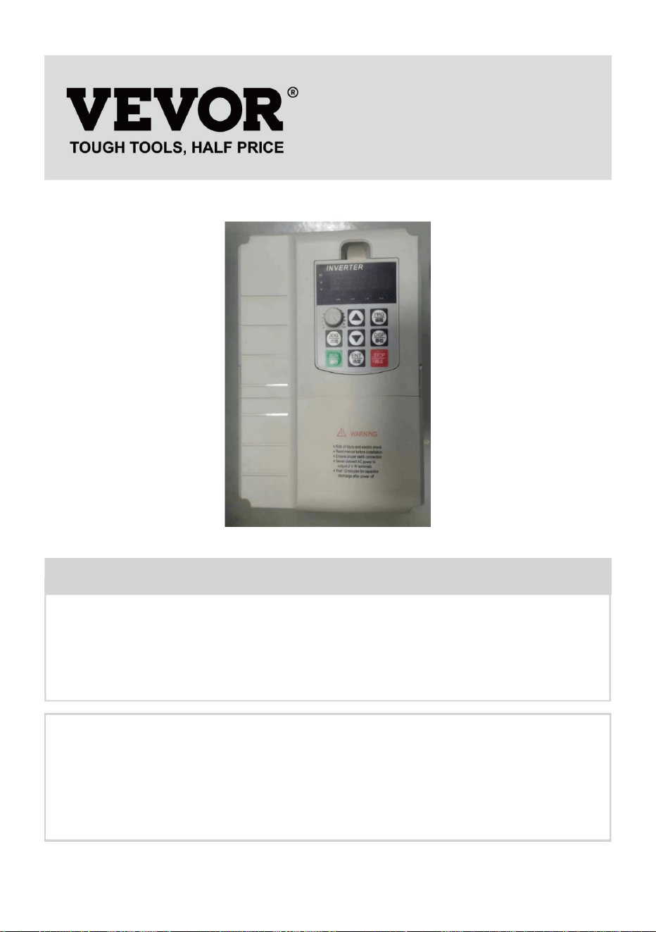
Haben Sie Fragen zum Produkt? Benötigen Sie technischen Support? Bitte kontaktieren Sie
uns:
Technischer Support und E-Garantie-Zertifikat www.vevor.com/
support
MODELL:AT1-7500X
Dies ist die Originalanleitung. Bitte lesen Sie alle Anweisungen sorgfältig durch, bevor
Sie das Gerät in Betrieb nehmen. VEVOR behält sich eine klare Auslegung unserer
Bedienungsanleitung vor. Das Erscheinungsbild des Produkts richtet sich nach dem
Produkt, das Sie erhalten haben. Bitte verzeihen Sie uns, dass wir Sie nicht erneut informieren,
wenn es Technologie- oder Software-Updates für unser Produkt gibt.
- 1 -
Brauchen Sie Hilfe? Kontaktieren Sie uns!
Wechselrichter
Machine Translated by Google

Lesen Sie alle Sicherheitshinweise, Anweisungen, Abbildungen und
WARNUNG: STROMSCHLAG- UND BRANDGEFAHR!
7. Die Installation dieses Wechselrichters und die dazugehörige Verkabelung müssen von einem qualifizierten
Elektriker unter Einhaltung aller geltenden Elektrovorschriften.
Die Abwicklung erfolgt über den Wiederverkäufer.
Wenn der externe Schalter das Gerät nicht neu starten kann, wenden Sie sich bitte an Ihren
6. Verwenden Sie kein Verlängerungskabel
Dieses Gerät kann jederzeit zerlegt werden, um Gefahren zu vermeiden. Nach einem Gerätedefekt
5. Stecken Sie das Netzteil direkt in eine GFCI-Steckdose für feuchte Standorte.
Bei diesem Gerät handelt es sich um ein Hochspannungsgerät. Versuchen Sie nicht,
4. Schließen Sie nicht zwei oder mehr Transformatoren parallel an
Ausrüstung .
WARNUNG:
3. Wechselrichter nicht untertauchen.
2. NICHT ZERLEGEN.
Die für die Einhaltung der Vorschriften verantwortlichen Personen können zum Erlöschen der Berechtigung des Benutzers zum Betrieb des
und/oder schwere Verletzungen.
Feuer und Stromschlag.
Die folgenden Anweisungen können zu Stromschlag, Brand oder
Änderungen oder Modifikationen an diesem Gerät, die nicht ausdrücklich von der Partei genehmigt wurden
Die Nichtbeachtung aller Spezifikationen dieses Wechselrichters
1. Die Nichtbeachtung dieser Anweisung kann zu einem elektrischen Defekt führen,
WARNUNG:
BEWAHREN SIE DIESE ANWEISUNGEN AUF
WICHTIGE SICHERHEITSHINWEISE
- 2 -
Machine Translated by Google

ACHTUNG: Änderungen oder Modifikationen, die nicht ausdrücklich von der Partei genehmigt wurden
von der für die Einhaltung verantwortlichen Partei genehmigt werden, kann zum Erlöschen der
Störungen des Funkverkehrs. Es gibt jedoch keine
garantieren, dass bei einer bestimmten Installation keine Störungen auftreten. Wenn dies
ACHTUNG: Änderungen oder Modifikationen an diesem Produkt, die nicht ausdrücklich
Störungen, die zu unerwünschtem Betrieb führen können.
Wenn die Installation und Verwendung nicht gemäß den Anweisungen erfolgt, kann dies zu
Hilfe.
2) Dieses Produkt muss alle Störungen akzeptieren, einschließlich
Dieses Produkt erzeugt und verwendet Hochfrequenzenergie und kann diese auch ausstrahlen.
ÿ Wenden Sie sich an den Händler oder einen erfahrenen Radio-/Fernsehtechniker für
1) Dieses Produkt kann schädliche Störungen verursachen.
in einer Wohnanlage.
folgende Maßnahmen. ÿ
Richten Sie die Empfangsantenne neu aus oder stellen Sie sie
woanders auf. ÿ Vergrößern Sie den Abstand zwischen Produkt und Empfänger. ÿ Schließen
Sie das Produkt an eine Steckdose an, die zu einem anderen Stromkreis gehört als der, an den das Produkt angeschlossen ist.
der Receiver ist angeschlossen.
die folgenden beiden Bedingungen:
ein digitales Gerät der Klasse B gemäß Teil 15 der FCC-Regeln. Diese Grenzwerte
sind so konzipiert, dass sie einen angemessenen Schutz gegen schädliche Störungen bieten
Der Benutzer wird aufgefordert, die Störung durch eine oder mehrere der folgenden Maßnahmen zu beheben:
Dieses Gerät entspricht Teil 15 der FCC-Bestimmungen. Der Betrieb unterliegt
Ausrüstung!
Hinweis: Dieses Produkt wurde getestet und entspricht den Grenzwerten für
Empfang, der durch Aus- und Einschalten des Produkts überprüft werden kann,
Konformitätsverantwortung kann zum Erlöschen der Berechtigung des Benutzers zum Betrieb des
Berechtigung zum Betrieb des Produkts.
Das Produkt verursacht keine Störungen beim Radio- oder Fernsehempfang.
FCC-Informationen
- 3 -
Machine Translated by Google

1. Produktinformationen
IN
Ausgabe
Aktuell:A
Stromvektor-Universalfrequenzumsetzer
Bremswiderstand
Frequenz
automatisch entsprechend der Belastung
Basic
10
Projekt
Frequenz
Leistung
600
0,5 kHz – 16 kHz
Adaptiver Motor
22 901-7K5G1
Fahren
V/F-Steuerung: 0 – 3200 Hz.
Regelungsmodus: Offene Vektorregelung (SVC)
Auflösung
Simulationseinstellung: ±0,025 %
Ohm
34,0
Hocheffizienter Antrieb des Induktionsmotors
AT901-Serie
7.5
Standard
Träger
Digitale Einstellung: 0,01 Hz
Maximal
Die Trägerfrequenz kann eingestellt werden
HPKW
Auflösung
40
Modell
System
Vektorsteuerung: 0-500 Hz
mit hoher Fusion aus Leistung und Funktion.
Frequenz
Funktion
und alle mit diesem Symbol gekennzeichneten Zubehörteile. Als solche gekennzeichnete Produkte
dürfen nicht mit dem normalen Hausmüll entsorgt werden, sondern müssen in einer
Sammelstelle für das Recycling von elektrischen und elektronischen Geräten
Das Handbuch enthält Vorsichtsmaßnahmen und Hinweise zur Auswahl des Benutzertyps.
durch bedeutet, dass das Produkt einer getrennten Entsorgung unterliegt
Sammlung in der Europäischen Union. Dies gilt für das Produkt
2012/19/EG. Das Symbol einer durchgestrichenen Mülltonne
Dieses Produkt unterliegt den Bestimmungen der europäischen Richtlinie
Installation, Parametrierung, Inbetriebnahme vor Ort, Fehlerdiagnose und
tägliche Wartung und Instandhaltung
1.2 Produktspezifikation
1.1 Wechselrichterserie
Richtige Entsorgung
- 4 -
Machine Translated by Google

- 5 -
Stabile Geschwindigkeit
Dec-Modus
Es kann leicht realisieren die Prozesssteuerung
geschlossener Regelkreis
Drehmomentanstieg
Jog-Frequenzbereich: 0,00 Hz – 50,00 Hz;
Begrenzung
und Kontrolle
Standard
Überlast
Bremsfrequenz: 0,00 Hz – Maximalfrequenz;
Bremszeit: 0,0 s – 36,0 s Bremsstromwert:
0,0 % – 100,0 %
Bereich von ADJ
Beschleunigungs- und Verzögerungsmodus in Geraden- oder S-Kurve, vier
Beschleunigungs-/Verzögerungszeiten, Beschleunigungs-/Verzögerungszeitbereich
Bis zu 16 Segmentgeschwindigkeitsläufe mit integrierter SPS oder Steuerung
Automatische Drehmomentbegrenzung während des Betriebs.
Sofortige Stromversorgung, um häufiges Auslösen durch Überstrom zu verhindern. Bei einem sofortigen Stromausfall ist eine
Unterbrechung der Stromversorgung erforderlich.
Betrieb
Typ-P-Modus: 0,3 Hz/100 % 1:100
(SVC) ±0,5 %
(SVC)
V/F-Kurve
Gesetzliche Kontrolle
Drehmomentgrenze
V/F-Steuerung
Kapazität
Gleichstrombremsung
Schneller Strom
Bedienfeld, Bedienterminal, Serielle Schnittstelle, kann auf
verschiedene Arten umgeschaltet werden
Projekt
0,0-6500,0 s
Genauigkeit
AVR-Funktion: Wenn die Eingangsspannung schwankt, kann die
Ausgangsspannung automatisch konstant gehalten
werden. Strom und Spannung werden automatisch begrenzt,
um häufiges Auslösen aufgrund von Überspannung zu verhindern.
Befehl
Geschwindigkeit
Kurve Acc/
Terminal
eingebauter PID
Timing
Anlaufdrehmoment
Beschleunigungs- und Verzögerungszeit: 0,0 s – 6500,0 s.
Typ G:150 % Nennstrom für 120 s; 180 % für 1T0ypse P:120
% Nennstrom für 60 s; 150 % für 3Aautomatische
Drehmomenterhöhung; MTharneueawl
taoyrsq:usetrianicgrhetalsinee:;0m.1u%lti--p3o0i.n0t%;
N sekundäre V/F-Kurve (1.2,1.4,1.6,1.8 und 2)
Stallkontrolle
Minimieren Sie den Überstromfehler und schützen Sie den
normalen Betrieb des Frequenzumrichters
Quelle
Typ-G-Modus: 0,3 Hz/150 % (SVC).
Machine Translated by Google

1.3 Beschreibung der Steuerschleife und des Hauptschleifenanschlusses
Standard
Terminal
Ebene
Umgebung
Projekt
1 Relaisausgangsklemme (TA, TB, TC)
Ausgabe
Über dem Meer
Weniger als 5,9 m/s (0,6 g)
1 digitaler Ausgangsanschluss
Ort verwenden
vibrieren
Ein 0–10-V-Spannungs- oder 0–20-mA-Stromeingang;
Funktion
Weniger als 95 % relative Luftfeuchtigkeit, wasserfreie Kondensation
Temperatur
Luftfeuchtigkeit
Quelle
Innenbereich, keine direkte Sonneneinstrahlung, kein Staub, keine
ätzenden oder brennbaren Gase, kein Ölnebel, kein Dampf, kein Wasser
oder Salz usw.
Schutz
-10 °C bis +40 °C (Umgebungstemperatur ist 40 °C bis 50
°C, bitte verringern Sie die Menge)
Frequenz
Eingangsanschlüsse: Fünf digitale Eingangsanschlüsse, 1
analoger Mengen-Eingangsanschluss;
Erkennung von Kurzschlüssen beim Einschalten des
Motors, Schutz vor Phasenverlust am Eingang und Ausgang,
Überstromschutz, Überspannungsschutz,
Unterspannungsschutz, Überhitzungsschutz und Überlastschutz
usw.
Schleife Die
Umwelt
Panelpotentiometer, Nummer angegeben, externer analoger
Spannungs-/Stromeingang und serieller Port-Eingang.
Kann auf verschiedene Arten umgeschaltet werden
1 analoger Ausgangsanschluss, unterstützt 0-10 V oder 0-20
mA Spannungsausgang
unter 1000m 2C116699
- 6 -
Machine Translated by Google
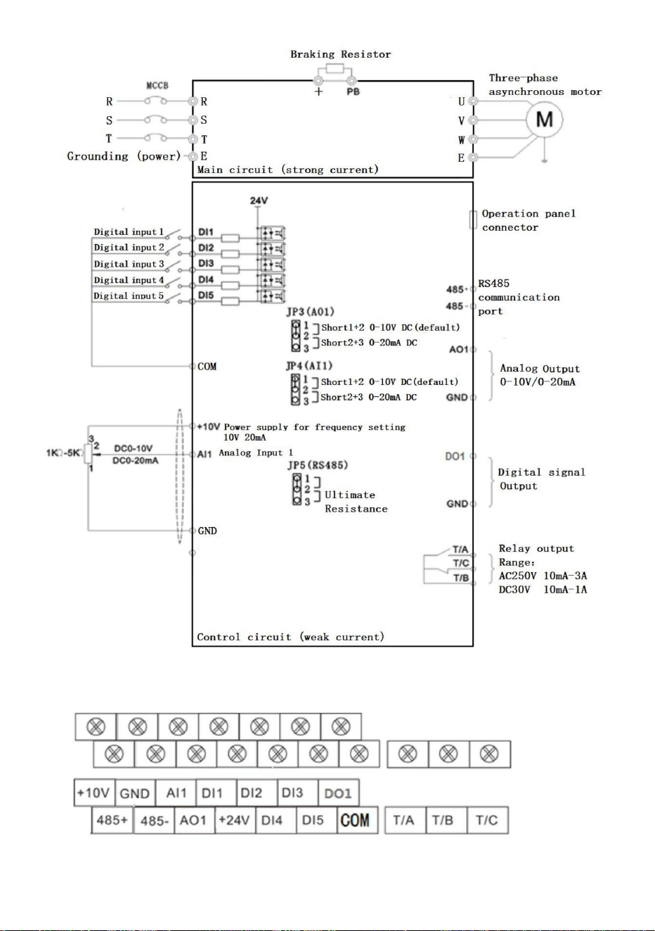
- 7 -
Abbildung 1-3-1 0,75-11,0 kW Schaltplan Steuerklemmenbeschreibung
Machine Translated by Google

Legen Sie die Parametermethode fest:
- 8 -
ÿ F / R: Vorwärts- und Rückwärtskontrollleuchte
Rufen Sie das Menü auf und bestätigen Sie die
Obere Taste
Ab-Taste
ÿ ERR: Störungsanzeigelampe
Änderung
ANZEIGE
ÿ V: Spannungsanzeigelampe
Funktionsdeklaration
HNO
Starten Sie den Wechselrichter unter der Tastatur
STOPPEN
Wählen Sie das Parametermodifiziererbit und die
Jog-Taste
Programmierung
Abnehmende Daten- oder Funktionscodes
Stop-/Reset-Taste Betrieb stoppen/reseten,
Schlüsselsymbol
Nach Abschluss der Arbeiten kehren Sie mit der Taste PRG zur Frequenzschnittstelle zurück .
Mit der ENTER- Taste wird der Parameter eingegeben.
ÿ L / R: Kontrollleuchte für Kommunikationssteuerung
Parametereinstellung
ÿ
LAUFEN
Menü betreten oder verlassen, mit Parameter
Schlüssel
Betriebsart
ÿ A: Stromanzeigelampe
JOGGEN Beschränkt auf den Funktionscode P08.01
ÿ Hz:Frequenzanzeige-Kontrollleuchte
Name
Bestimmen Sie die
Inhalt anzeigen
PRG
Beschreibung der Funktionsanzeigelampe
Schlüssel
ÿ RUN: Betriebskontrollleuchte
Inkrementieren von Daten- oder Funktionscodes
ÿ
Führen Sie den Schlüssel aus
3. ÿ ÿ und DISP Tasten ändern Parameterwerte, ENTER Taste Parameter speichern, 4. Wenn Sie andere Parameter
ändern müssen, wiederholen Sie 2,3, Schritte, wie Änderung
Umschalttaste
1. Drücken Sie die Taste PRG , um P 0.00 anzuzeigen. 2. Wählen
Sie mit den Tasten ÿ ÿ und DISP die zu ändernde Parameternummer aus.
2. Bedienung und Anzeige
Machine Translated by Google

- 9 -
3. Übersichtstabelle der Funktionsparameter:
P00.04
Ausgangsstrom (A)
P00.15
AI1 Spannung vor der Korrektur
-
Zählwert
0 ÿ 32767
0,000 V ÿ 10,570 V
P00.25
Rückkopplungsgeschwindigkeit (Hz)
P00.00
-
Sammelschienenspannung (V)
0,00 mA ÿ 20,00 mA
Lineargeschwindigkeit
P00.18
-
0 ÿ 32767
0 ~ 100 kHz
P00.07
PID-Einstellung
P00.22
0 ÿ 65535 m/Min
-
0,00 ÿ 320,00 Hz (P01.22 = 2) –
AI1 Spannung (V)
-
P00.14
-
0 ÿ 65535
P00.03
P00.24
0 V bis 1140 V
-
-
P00.21
-
OF-Eingangszustand
0,0 ÿ 6500,0 Min
Pulseingangsfrequenz
P00.10 AI2 Spannung (V) oder Strom (mA)
-100,00 % ÿ 100,00 %
-
Stellen Sie die Frequenz ein
-
P00.06
P00.17
Ausgangsleistung (kW)
0 ÿ 65535
Kommunikationseinstellungen
Drehzahlanzeige laden
-
0,000 mA ÿ 20,000 mA
-
P00, Überwachungsgruppe
0 ÿ 1023
P00.13
-
Ausgangsspannung (V)
0 ÿ 65535
P00.02
-
P00.20
-
-3200,0 Hz ÿ 3200,0 Hz
P00.09
P00.28
-200,0 % ÿ 200,0 %
-
SPS-Stufe
0,00 V ÿ 10,57 V
0,0 ÿ 6500,0 Min
Aktuelle Laufzeit
0,0 ÿ 3200,0 Hz (P01.22 = 1) -
-
P00.05
P00.16
0,00 A bis 655,35 A
0 ÿ 65535
Korrektur
Längenwert
AI2 Spannung/Strom vor
DO-Ausgangszustand
0,000 V ÿ 10,570 V
-
-
Verbleibende Laufzeit
P00.01
P00.12
0,0 V ÿ 3000,0 V
0 ÿ 65535
P00.26
P00.19
-
-320,00 Hz ~ 320,00 Hz
P00.08
Aktuelle Leistung Zeit
Ausgangsdrehmoment (%)
-
PID-Rückmeldung
Lauffrequenz
0,01 V
0 bis 6500 Min
-
-
0 ÿ 65535
Machine Translated by Google

-
P00.40 Ausgangsspannung der VF-Trennung
1: Typ G (konstante Drehmomentbelastung
-
G/P-Typ
P00.44 DI-Funktionsstatus optische Anzeige 2
0 V ~ Motornennspannung
P01.01
-
ändern
Zieldrehmoment, (%)
P00-61
Modell)
P00.42
-
-100,00 % ÿ 100,00 %
Modus
-
ÿ—nicht veränderbarer Parameter im Ausführungsstatus
•—der aktuell erkannte Parameter, nicht veränderbar
P00.31
P00-59
P01 Basische funktionelle Gruppe
Kanal („L/R“-Leuchten aus)
0,00 Hz bis 500,00 Hz
-
P00.39 Zielspannung der VF-Trennung
-
P01.00
DI-Funktion Statusanzeige 1
-
2 ÿ
P00-60
-
Bereich festlegen
P00.35
-
2: Typ P (Lüfter und Wasserpumpe
Statusanzeige des IN-Eingangs
-
1. Motorsteuerung
-
ÿ—veränderbarer Parameter unter allen Bedingungen
Frequenz X Anzeige
Fehlermeldung
Wert
0: Befehl zum Ausführen über das Bedienfeld
Leistungsfaktor Winkel
0,00 Hz bis 500,00 Hz
(Funktion 41. Funktion 80)-
Kontrolle
-
0 ÿ 65535
P00.43
FC
Befehl
Ausführungshäufigkeit (%)
-
P00.32 Einen beliebigen Speicheradresswert anzeigen
P01.02
-
Modell)
P00.41
0,0°ÿ 359,9°
1 ÿ
P00-45
0 V ~ Motornennspannung
-
P00.30
2: V/F-Steuerungsmodell
(Funktion 01. Funktion 40)-
Name
P00.37
Wechselrichterzustand
0: Geschwindigkeitssensorloser Vektor
-
-100,00 % ÿ 100,00 %
DO-Eingangsstatusanzeige
Fabrik
Betrieb
Frequenz Y Anzeige
Stellen Sie die Häufigkeit (%) ein.
-
0 ÿ
0 ÿ 65535
- 10 -
Machine Translated by Google

1: Digitaleinstellung (voreingestellte
Frequenz P01.08, Tastenfeld ÿ/ÿ,
Speicher für Leistungsabfall)
Wie P01.03
(Hauptfrequenzquelle X) eingestellt
Y bei
Frequenzüberlagerung
Grenze von Y, wenn
0: Digital eingestellt (voreingestellte
Frequenz P01.08, Tastenfeld ÿ/ÿ,
Stromausfall)
Sekundärfrequenzquelle
P01.07 Frequenzquelle
Kanal
8: PID-Regelung eingestellt;
0 ÿ
0: Hauptfrequenzquelle X
Frequenzüberlagerung
UND
0 % ÿ 150 %
Kanal
Quelle X
2: AI1 Analog-Set (0–10ÿV);
3: AI2 Analog-Set (0–10ÿV oder
20ÿmA);
4: Panel-Potentiometer; 5:
Impuls-Set (0–50ÿkHz DI5); 6:
Mehrstufiger Geschwindigkeitslauf-
Set 7: Einfaches PLC-Set;
0 ÿ
100 % ÿ
9: Kommunikationssatz.
P01.05
1: Haupt- und Nebenbetrieb
(L/R“-Lichter blinken)
2: Kommunikationsbefehl
P01.03
Auswahl einschränken auf
Eine Ziffer: Frequenzquellenauswahl
1: Terminal Run-Kanal („L/R“ leuchtet)
4 ÿ
0: Im Vergleich zur ÿP01.10ÿ
Maximalfrequenz 1:
Relativ zur Frequenzquelle X
Hauptfrequenz
P01.04
P01.06
00
- 11 -
Machine Translated by Google

4: Die Frequenz Y wechselt mit
Präpositionshäufigkeit
0 ÿ
P01.09 Laufrichtung
Ergebnisse der Sekundäroperation
3:
P01.10
50,00
3: Umschalten zwischen Haupt-
2: Maximum von beiden,
ÿ
50,00
Obere
Grenzfrequenz
P01.13
2000,00 Hz
P01.11
0,00 Hz ÿ ÿP01.10ÿ
Gegenrichtung
50,00 Hzÿ
0 ÿ
Ergebnisse (Operationsbeziehung
wird durch zehn Ziffern bestimmt)
Zehn Ziffern: Frequenzoperationsbeziehung
von X und Y
P01.12
ÿP01.14ÿÿ ÿP01.10ÿ
Haupt- und Nebenbetrieb
0,00 Hz ÿ Maximale Frequenz ÿP01.10ÿ
Vektor: 50,00 Hz ~ 500,00 Hz
0: ÿP01.12ÿ Einstellung 1:
AI1 Einstellung
2: Al2 Einstellung
3: AI3
Einstellung 4: Impulseinstellung (0ÿ
50KHZ DI5); 5: Kommunikations-Setup
Das Minimum von beiden.
P01.08
Hz
Frequenz X und Main und
Oberer
Grenzwert für Frequenzbias
Quelle
0,00 Hz ÿ
Sekundärfrequenz Y-Schalter
1:X-Y
Hz
Maximale
Ausgangsfrequenz
2: Hauptfrequenz X und
0:X+Y
50,00
Ergebnisse
0: Konstante Richtung, 1:
V/F:
Obere
Grenzfrequenz
ÿ
ÿ
Hz
- 12 -
Machine Translated by Google

P01.22
1 ÿ
Frequenzanweisung
0: Motorparametergruppe 1,
1: Motorparametergruppe 2.
0,0 s ÿ 6500,0 s (P01.19=1)
Bias-Frequenz der
Frequenz Y bei
Ausschalten
0 ÿ
Für Modell ÿ
Zeiteinheit von
0 ÿ
Beschleunigungszeit
2: 0,01 Sekunden
Auswahl der
Motorparametergruppe
0,00 Hz ÿ
Referenz
P01.15 Trägerfrequenz
Verzögerungszeit
Laufzeit
P01.19
2 ÿ
Mit der
Temperatur anpassen
0: Kein Speicher 1: Speicher
1
1 ÿ
1
Frequenz
Beschleunigung und
P01.14
Digitale
Frequenzeinstellung
1: Frequenz einstellen
0: Nein,1: Ja
Verzögerungszeit
P01.21
0 ÿ
Frequenz
0 s bis 65000 s (P01.19 = 0)
Verzögerungszeit
Trägerfrequenz
Sekunden
Befehle.
AUF/AB
ÿ
P01.23
P01.17
Häufigkeit von
Referenzfrequenz ÿP01.25ÿ
Auflösung von
0,00 Hz ÿ
Speicher für
0: Betriebsfrequenz,
P01.16
1: 0,1 Sekunden
Für Modell
0,00 Hz ÿ Maximale
Ausgangsfrequenz ÿP01.10ÿ
P01.24
Untergrenze
Auflösung aller Frequenzen
P01.25
0,5 kHz ÿ 16,0 kHz
0:1
P01.26
ÿ
0 ÿ
0,00 s – 650,00 s (P01.19 = 2)
0: Maximale Frequenz ÿP01.10ÿ 1:
Einstellfrequenz 2:100Hz
0,00 Hz ÿ ÿP01.12ÿ
P01.18
Überlagerung
Beschleunigung und
- 13 -
Machine Translated by Google

7: Einfache SPS
Auswahl
Motortyp
8: PID-Wert
P02 Asynchronmotor Parametergruppe 1
Motor
ÿ
Einstellige Zahl: Häufigkeit der
Befehlsbindung im Bedienfeld
gebündelt
Tausenderstelle: Automatisches
Ausführen der Bindungsfrequenzquelle
5: Impulssatz (0ÿ50KHZ DI5);
P01.27
0 ÿ
ÿ
Wechselrichter
0,01 A bis 655,35 A
0,1A~6553,5A
1: Digitales Set
9: Kommunikationsset
0: gewöhnlicher Asynchronmotor,
P02.01
P02.02
ÿ
Quellenauswahl
Frequenzquelle
Auswahl
Nennspannung von
Von den
P02.03
Benchmark
100-stellig: Kommunikationsbefehl
Bindung Frequenzquellenauswahl
Befehlsquelle
Nennleistung von
zur
(Wechselrichterleistung > 55kW)
6: Mehrsegmentgeschwindigkeit;
Zehnstellige Zahl: Quelle der
Terminalbefehlsbindungsfrequenz
P02.00
Nach
(Wechselrichterleistung <=55kW)
Motor
2:AI1 3:AI2 4:AI3
1: Asynchronmotor mit
variabler Frequenz
0000 ÿ
Motor
0,1 kW ÿ 400,0 kW
Modell
1 V bis 2000 V
Bemessungsstrom von
0: Keine Bindung
- 14 -
Machine Translated by Google

P02.05
ÿ
P02.08
P02.06
(Wechselrichterleistung <=55kW)
des Motors
(Umrichterleistung
> 55kW) 0: Kein
Betrieb 1: Optimierung bei
Motorstillstand 1 2:
Dynamische Optimierung des
Motors 3: Optimierung bei Motorstillstand 2
des Motors
0,001ÿ ÿ 65,535ÿ (Wechselrichterleistung
<= 55 kW) 0,0001ÿ
ÿ 6,5535ÿ (Wechselrichterleistung > 55
kW) 0,001ÿ ÿ
65,535ÿ (Wechselrichterleistung <= 55
kW) 0,0001ÿ ÿ
6,5535ÿ (Wechselrichterleistung > 55 kW)
0,01 mH ÿ 655,35
mH
Dichtheit
P02.04
Rotorwiderstand
ÿ
(Wechselrichterleistung > 55kW)
ÿ
0 ÿ
Drehzahlregler
proportional 1
0,01 Hz – Maximale
Ausgangsfrequenz ÿP01.10ÿ
des Motors
0,001 mAh bis 65,535 mH
ÿ
0,1 A bis P02.03
Nenndrehzahl von
Statorwiderstand
des Motors
P02.09
der Motor
30 ÿ
Nennfrequenz
P02.07
1 U/min ÿ 65535 U/min
(Wechselrichterleistung > 55
kW) 0,1 mH ÿ 6553,5 mH
(Wechselrichterleistung <= 55 kW)
Leerlaufstrom von
P03.00
ÿ
des Motors
Parameter
0,01 A ÿ P02.03
(Wechselrichterleistung <= 55 kW)
P03 Vektorregelungsparameter der Motorgruppe 1
ÿ
Tuning
ÿ
Gegenseitiger Widerstand
0,01 mH ÿ 655,35 mH
P02.10
P02.37 Tuning-Auswahl
1 bis 100
Motor
- 15 -
Machine Translated by Google

P03.10
Geschwindigkeitsregler-Integrationszeit 2
Erregung
0,01 s ÿ 10,00 s
Drehzahlregelung
0 ÿ
P03.15 Proportionalverstärkung
5,00 Hz ÿ
100 % ÿ
20 ÿ
Konstanten
Proportionaler Gewinn
von
4: Impulssatz (DI5);
P03.14
0,50 s ÿ
P03.05
SVC-
Drehmomentfilterzeit
150,0 % ÿ
Drehzahlregler
proportional 2
0 ÿ 60000
P03.04
Quelle unter
50 % ÿ 200 %
7: MAX (AI1, AI2)
Verordnung
0,00 ÿ ÿP03.05ÿ
Steuermodus
1 bis 100
0,000 s ÿ 0,100 s
3: AI3;
Integraler Verstärkungsgewinn
der Anregung
Schaltfrequenz
10,00 Hz ÿ
0 ÿ 60000
1
die Schaltverstärkung
Obere Drehmomentgrenze
unter Drehzahl
Drehmoment-Obergrenze
P03.13
1,00 s ÿ
1300 ÿ
Vektorsteuerung von
6: MIN (AI1, AI2)
0,01 s ÿ 10,00 s
0,0 % ÿ 200,0 %
Schaltfrequenz
P03.07
P03.02 ÿMaximale Ausgangsfrequenz
ÿP01.10ÿ
Modus
Verordnung
Drehzahlregler-
Integrationszeit 1
P03.09
2000 ÿ
P03.02
P03.06
0: P03.10 Einstellung
1: AI1; 2: AI2;
2000 ÿ
P03.03
0 ÿ 60000
P03.01
2
5: Kommunikationseinstellungen;
0,050 s ÿ
- 16 -
Machine Translated by Google

1: Mehrpunktkurve V/F 2:
Kurve 1 mit abnehmendem
Drehmoment (quadratische Kurve)
Einstellung der
Drehmomentverstärkung
Abschaltpunkt der
Drehmomentverstärkung
Mehrpunkt-
V/F-Frequenz 1
Mehrpunkt-V/F-Spannung 1 Mehrpunkt-V/F-Frequenz 2 Mehrpunkt-V/F-Spannung 2
0,00 Hz ÿ
8: Kurve 2 mit abnehmendem Drehmoment
(1,8 Leistung)
0,00 Hz ÿ Maximale
Ausgangsfrequenz ÿP01.10ÿ
ÿP04.03ÿ ÿ ÿP04.07ÿ
0,0 % ÿ
Drehmomentregelung
4: Kurve 2 mit abnehmendem Drehmoment
(1,4 Leistung)
P04.01
P04 V/F-Steuerparameter
P04.00 VF-Kurveneinstellung
P04.03
P04.06
P03.16
10: VF vollständig getrennter Modus
50,00 Hz ÿ
0,00 Hz ÿ
Integralverstärkung
der Drehmomentregelung
6: Kurve 2 mit abnehmendem Drehmoment
(1,6 Leistung)
0,1 % bis 30,0 %
0,0 % ÿ 100,0 %
von
Nach Modell ÿ
3: Kurve 2 mit abnehmendem Drehmoment
(1,2 Leistung)
0,0 % ÿ
0: lineare Kurve V/ F
11: VF-Halbtrennungsmodus 0,0
% (Automatisches Hubdrehmoment);
0,00 Hz ÿ ÿP04.05ÿ
0,0 % ÿ 100,0 %
0 ÿ 60000
P04.02
0 ÿ
P04.04
P04.05
1300 ÿ
- 17 -
Machine Translated by Google

0,0 % ÿ
64 ÿ
4: Impulseinstellung (DI5)
Anregungsverstärkung
Nach Modell ÿ
VF getrennt
Spannung für
VF-Trennung
ÿP04.05ÿÿ Motorleistung
0,0 % ÿ 200,0 %
0 ÿ 200
P04.08
Unterdrückungsgewinn
2:AI2
7: Der PID
0,0 s ÿ 1000,0 s
0,0s ÿ
Nennspannung des Motors.
0,0 s ÿ 1000,0 s
P04.07
Schwingung
0: Digitale Einstellungen ÿP04.14ÿ
0 ÿ
Hinweis: Zeit, wenn 0V steigt auf
0: Frequenz und Spannung fallen
getrennt auf 0;
Spannungsabfall auf 0 -
18 -
P04.17
Frequenz ÿP02.04ÿ
V/F Über
0 ÿ 100
Spannungsquelle durch
0 V ÿ Motornennspannung
P04.16
Mehrpunkt V/F
Freq. 3
Mehrpunkt V/F
Spannung
3 V/F Steuerung
Schlupffrequenzkompensation
P04.10
P04.09
5: Mehrfachanweisung
Spannungsanstiegszeit
der VF-Trennung
Spannungsabfallzeit
der VF-Trennung
der VF-Trennung
0 ÿ
0,0 % ÿ 100,0 %
für V/F
3:AI3
8: Kommunikation
Einstellung Hinweis: 100,0%,
entspricht der Motornennspannung
P04.15
Hinweis: Zeitpunkt, an dem die
Nennspannung des Motors auf 0 V fällt
Abschaltmodus
0,0 % ÿ
1:AI1
P04.11
6: Einfache SPS
P04.13
P04.14
0 V ÿ
0,0s ÿ
1: Frequenz sinkt nach dem
0,00 Hz ÿ
Machine Translated by Google

- 19 -
1: Vorwärtslauf (FWD) oder
ÿ
1
Entschädigung
30 ÿ
5 Hz ÿ
150 % ÿ
Überspannungs-Blockier-
Aktionsspannung
Unterdrückung von
Überspannungs-Blockier-
Frequenzverstärkung
der Unterdrückung
von Überspannungs-Blockier-
Spannungsverstärkung
der Unterdrückung von
Überspannungs-Blockier-Spannungsverstärkung
20 ÿ
1 ÿ
DI1-Klemme
Maximaler Anstieg
5: Rückwärts-Jog-Steuerung (RJOG)
Aktionsstrom
aktueller Stand
650,0 V – 800,0 V
0: Keine Funktion;
1: Aktivieren.
P05.00
aktueller Stand
0 ÿ 100
50 % ÿ
0 ÿ 50 Hz
Überstromstillstand
2: Rückwärtslauf (REV) oder
Unterdrückungsgewinn von Über
P04.23
0 ÿ 100
3: Dreidraht-Laufsteuerung 4:
Vorwärts-Jog-Steuerung (FJOG)
P04.18
Aktion Über
0: Deaktivieren,
P04.22
P05-Gruppe, Eingabeparameter
P04.24
ÿ
0 ÿ 100
50 % ÿ 200 %
Überspannungsstillstand
P04.19
Läuft;
1
1: Aktivieren.
Koeffizient von
P04.25
Vorwärts-/Rückwärtsschalter
Überstromstillstand
P04.26
50 % ÿ 200 %
760,0 V ÿ
30 ÿ
Funktion
P04.20
Unterdrückung von
P04.21
Frequenzgrenze für
0: Deaktivieren,
Machine Translated by Google

- 20 -
7: Frequenz verringern (Klemme
NACH UNTEN)
22: PID-Regelung Pause
33: Externer Fehlereingang (normalerweise
6: Frequenzerhöhung (Klemme nach oben)
21: VFD ACC/DEC verbieten
Klemme 1
32: Gleichstrombremsung sofort;
20: Befehlsschalter ausführen
31: Reserviert;
18: Frequenzquellenschalter 19: UP/
DOWN Frequenz Null löschen
(Terminal, Tastatur)
27: Längenzähleingang 28:
Längenrücksetzung
29: Drehmomentregelung deaktivieren
30: Impulseinstellung (nur DI5 kann
eingestellt werden, P05.04=30)
17: ACC/DEC-Zeitauswahl 2 (TT2)
25: Zählereingang
26: Zähler zurückgesetzt
10: Betrieb unterbrechen; 11:
Externer Fehler, normalerweise offener (NO)
Eingang 12:
Mehrfachgeschwindigkeit
1 13: Mehrfachgeschwindigkeit
2 14: Mehrfachgeschwindigkeit
3 15: Mehrfachgeschwindigkeit
4 16: ACC/DEC-Zeitauswahl 1 (TT1)
9: Externer Reset-Signaleingang
(RST)
24: Pendelfrequenz Pause
8: Freie Abschaltsteuerung
23: PLC-Zustand zurückgesetzt
Machine Translated by Google

- 21 -
39: Frequenz X schaltet mit der
voreingestellten Frequenz
49: Langsame Gleichstrombremsung
DI4-Klemme
44: Benutzerdefinierter Fehler 1
52: Umkehrsperre;
(nur DI5 kann
12 ÿ
34: Frequenzänderung
41: Motorauswahl Klemme 1
51: Zweidrahtsteuerung / Dreidrahtsteuerung
Terminal 2
47: Not-Halt
DI3-Klemme
9 ÿ
36: Außenparkplatz Terminal 1
45: Benutzerdefinierter Fehler 2
DI2-Anschluss
4 ÿ
Ermöglicht
43: Der PID-Parameterschalter
Steuerschalter
Funktion
13 ÿ
geschlossenÿNCÿ
50: Laufzeit gelöscht;
40: Frequenz Y schaltet mit der
voreingestellten Frequenz
Funktionalität
P05.03
38: PID-Integral-Pause;
48: Außenparkplatz Terminal 2
Funktionalität
P05.02
37: Befehlsschalter ausführen
Funktionalität
46: Schalter für Drehzahlregelung/
Drehmomentregelung
DI5-Klemme
P05.01
P05.04
35: PID-Eingangssignal umgekehrt;
Machine Translated by Google

- 22 -
0,00 V ÿ P05.20
Modus
2er Min. Eingang
0,001 Hz/s – 65,535 Hz/s
P05.16
P05.17
10,00 V ÿ
2: Dreidraht-Steuerung Modus 1,
Entsprechend
Frequenz
P05.13 ÿ +10,00 V
Entsprechend
-100,0 % ÿ +100,0 %
Wert der AI-Kurve
P05.10 DI-Filterzeit
Kurve 1
-100,0 % ÿ +100,0 %
0,0 % ÿ
P05.18
Terminalsteuerung
Wert der AI-Kurve
P05.12
Entsprechend
0,00 V ÿ P05.15
0,10 s ÿ
P05.18 ÿ +10,00 V
1: Zweidraht-Steuerung Modus 2,
Eingang
P05.11
Kurve 1
100,0 % ÿ
Entsprechend
Funktion,
P05.04=30)
Min. KI-Einsatz
P05.21
0,010s ÿ
Wert der AI-Kurve
Min. der KI-Kurve 2.
P05.15
P05.19
1,00 Hz/s ÿ
-100,0 % ÿ +100,0 %
P05.13
Zeit
0: Zweidraht-Steuerungsmodus 1,
0,00 V ÿ
0 ÿ
1er Min. Eingang
Max. Eingang von AI
Größe
Wert der AI-Kurve
P05.20 Max. Eingang von AI2
Einstellung Puls
0,00 s ÿ 10,00 s
100,0 % ÿ
3: Dreidraht-Steuermodus 2.
P05.14
10,00 V ÿ
0,0 % ÿ
Einstellschritt
2er Max. Eingang
0,000 s ÿ 1,000 s
0,00 V ÿ
1er Max.
Eingang AI Kurve 1 Filterung
-100,0 % ÿ +100,0 %
Machine Translated by Google

- 23 -
Entsprechend
Entsprechend
(14:00 Uhr, siehe P05.23 ~ P05.26.)
P05.32
P05.25
Entsprechend
P05.23 ÿ +10,00 V
(14:00 Uhr, siehe P05.18 ~ P05.21.)
-10,00 V ÿ
-100,0 % ÿ +100,0 %
P05.24
P05.28
Wert von Pulse
Wert von Pulse
1: Ich habe 1 Hure
Zeit
Entsprechend
P05.33 AI-Kurvenauswahl
P05.27
Impulseingang
Eingang
Zeit
10,00 V ÿ
Impulseingang
P05.26
-100,0 % ÿ +100,0 %
2: Ich habe 2 Huren
0,00 s ÿ 10,00 s
P05.31
0,0 % ÿ
Min. Wert von
P05.29
Einzelbit: AI1-Kurvenauswahl
P05.22
Kurve 3
321 ÿ
-10,00 V ÿ P05.25
0,10 s ÿ
P05.30
0,00 V ÿ
Max.
Eingangsimpulsfilterung
3er Min. Eingang
Max. Eingang von AI
(14:00 Uhr, siehe P05.13 ~ P05.16.)
3's Max. Eingang
AI Kurve 3 Filterung
Max. Wert von
0,10 s ÿ
100,0 % ÿ
Wert der AI-Kurve
Zeit
P05.23 ÿ +10,00 V
0,0 % ÿ
0,00 s ÿ 10,00 s
AI-Kurve 2-Filterung
10,00 V ÿ
3: Ich habe 3 Huren
P05.23
100,0 % ÿ
-10,00 V ÿ P05.25
-100,0 % ÿ +100,0 %
-100,0 % ÿ +100,0 %
0,10 s ÿ
Min. der KI-Kurve 3.
Wert der AI-Kurve
Min. Eingabe
0,00 s ÿ 10,00 s
Machine Translated by Google

- 24 -
Zehn Bit: AI2 unter Min.
Eingangseinstellung (dasselbe wie Einzelbit 1–2)
P05.35 DI1 Verzögerungszeit
Klemme DI1-DI5
Eingangseinstellung
0,0s ÿ
Zehn Bit: DI2;
0: Hohe Wirksamkeit, 1: Niedrig
(16:00 Uhr, siehe P24.00ÿP24.07)
Die KI ist unten
P05.37 DI3 Verzögerungszeit
(das gleiche wie oben)
P05.34
0,0 s ÿ 3600,0 s
Zehntausend Bit: DI5
Einzelbit: DI6,
P05.38
P05.39
Zehn Bit: AI2-Kurvenauswahl (dasselbe
wie Einzelbit 1–5)
Auswahl
0,0 s ÿ 3600,0 s
Hunderterbit: DI3;
5: Ich habe Huren 4
das Minimum
0,0 s ÿ 3600,0 s
Einzelbit: DI1;
Modusauswahl
4: Ich habe 4 Huren
P05.36 DI2 Verzögerungszeit
Hunderterbit: AI3 unter Min.
Eingangseinstellung (wie oben)
gültig
gültig
Einzelbit: AI1 unter Min.-
Eingangseinstellung 0: Entsprechender
Wert
von Min.-Eingang 1: 0,0 %
0,0s ÿ
0: Hohes effektives Niveau, 1: Niedriges
effektives Niveau
Klemme DI6-D17
00000 ÿ
Hundert Bit: AI3-Kurvenauswahl
0,0s ÿ
000 ÿ
Modusauswahl
Tausend Bit: DI4,
Niveau effektiv
00000 ÿ
(16:00 Uhr, siehe P24.08ÿP24.15)
Machine Translated by Google

5: VFD-
Nulldrehzahlbetrieb (beim Betrieb)
11: Der PLC-Zyklus ist abgeschlossen
13: Frequenzbegrenzung
Frühwarnung
2 ÿ
17: Ausgangsfrequenz erreicht Obergrenze
P06-Gruppe, Ausgabeparameter
0 ÿ
Relais
3: Frequenzpegel-Erkennungssignal
1 (P14T1)
9: Der angegebene Zählerstand ist erreicht
Auswahl
19: Unterdruck-Statusausgabe 20:
Kommunikationseinstellung 21:
Standort ist abgeschlossen
(reserviert) -
25 -
Funktionsauswahl
8: Der Set Count kommt
P06.02
Limit
DO1-Ausgang
7: Wechselrichterüberlastung
(TA-TB-TC)
16: AI1 > AI2
Zehn Bit: DI7
12: Kumulierte Laufzeit
6: Motorüberlastung Frühwarnung
14: Drehmomentbegrenzung
4:
Frequenzankunftsanzeige (FAR)
10: Länge erreicht
kommt an
0: Kein
Ausgang 1:
Betriebsanzeige; 2: Fehlerausgang
(für freien Abschaltfehler)
Funktion
Steuerplatine
15: Betriebsbereit
18: Ausgangsfrequenz erreicht
Untergrenze (beim Betrieb)
P06.01
Machine Translated by Google

- 26 -
23: Stillstand 2 (wird auch beim
Herunterfahren ausgegeben)
Abschaltfehler und kein Unter
P06.08
1 ÿ
22: Standortnähe (reserviert)
39: Motorüberhitzung
Vorwarnung
40: Diese Laufzeit wird erreicht
41: Fehlerausgang (für freie
38: Fehlerausgang (alle Fehler)
0 ÿ
Temperatur erreicht 36:
Ausgangsstrom außerhalb des
Grenzwertes 37: Ausgangsfrequenz
erreicht Untergrenze (Abschaltung auch Ausgang)
P06.07
35: Das Power-Modul
Auswahl der
AO2-Ausgangsfunktion
26: Ausgangsfrequenz 1 erreicht
27: Ausgangsfrequenz 2 erreicht
28: Ausgangsstrom 1 erreicht 29:
Ausgangsstrom 2 erreicht 30: Regulär
erreicht 31: Eingangssignal
Al1 überschritten 32: Lastabfall 33:
VFD-Rückwärtslauf 34:
Nullstromzustand
2: Ausgangsstrom, 3:
Ausgangsdrehmoment,
4: Ausgangsleistung,
5: Ausgangsspannung,
Auswahl der
AO1-Ausgangsfunktion
25: Frequenzpegel-Erkennungssignal
2 (P14T2)
kommt an
0: Betriebsfrequenz, 1:
Eingestellte Frequenz
24: Kumulierte Einschaltzeit
Druckausgang)
Machine Translated by Google

- 27 -
0,0 s ÿ 3600,0 s
Entspricht 1000,0 V)
Statusauswahl
AO1 Null-Bias
P06.13
RELAY2-Ausgang
12: Kommunikationseinstellung,
13: Motordrehzahl
P06.17
bezogen auf die Motorleistung)
-10,00 ÿ +10,00
0,0 s ÿ 3600,0 s
0,0s ÿ
Zehn Bit: RELAY1
8:AI2
AO2 Null-Bias
P06.10
P06.18
15: Ausgangsspannung (100,0%
DO-Ausgang gültig
relativ zur VFD-Bewertung)
0,0 % ÿ
DO-Ausgangsverzögerung
Verzögerungszeit
11: Zählwert
P06.19
(Prozentsatz des tatsächlichen Wertes
P06.11
1,00 ÿ
P06.22
7:AI1
AO1-Verstärkung
Entspricht 1000,0A)
0,0 % ÿ
0,0s ÿ
-100,0 % ÿ +100,0 %
Einzelbit: DO
(Prozentsatz des tatsächlichen Wertes
AO2-Verstärkung
RELAY-Ausgang
10: Länge
0,0s ÿ
16: Motorausgangsdrehmoment
1,00 ÿ
Koeffizient
-10,00 ÿ +10,00
00000 ÿ
6: Eingangspulsfrequenz.
Verzögerungszeit
14: Ausgangsstrom. (100,0 %
Zeit
P06.12
0: Positive Logik, 1: Anti-Logik
17: VFD-Ausgangsdrehmoment
9:AI3
Koeffizient
0,0 s ÿ 3600,0 s
-100,0 % ÿ +100,0 %
Machine Translated by Google

- 28 -
Zeitverhältnis von Start
Geschwindigkeitsverfolgung
Segment in S
Geschwindigkeit der
Geschwindigkeitsverfolgung
P07.06
2: S-Kurve Beschleunigungs-/Verzögerungsmodus B
P07.00 Startmodus
DC-Bremsstrom
P07.01
0 % ÿ
Segment in S
Beschleunigen
30,0 % ÿ
0: Direktstart
0,00 Hz ÿ
0,0s ÿ
Verzögerungsmodus
1: Beginnen Sie mit der
Arbeitsfrequenz
P07.09
1 bis 100
0,0s ÿ
Haltezeit
1: S-Kurve Beschleunigungs-/Verzögerungsmodus A
0 ÿ
P07.08
0 ÿ
0 % ÿ 100 %
Start-up
30,0 % ÿ
P07-Gruppe, Start- und Stopp-Steuerungsparameter
P07.02
Frequenz
0,00 Hz bis 10,00 Hz
P07.07
DC-Bremszeit bei
Zeitverhältnis von Start
Frequenz
Start-Häufigkeit
0: linearer Acc/Dec-Modus
2: Gleichstrombremsung + Start mit
Startfrequenz
0,0 %ÿÿ100,0 %-P07.09ÿ
Verfahren
0,0 s ÿ 100,0 s
20 ÿ
0,0 s bis 100,0 s
0,0 %ÿÿ100,0 %-P07,08ÿ
Hundert Bit: RELAY2
0 ÿ
0: Beginnen Sie mit dem Herunterfahren
P07.05
beim Start
Kurve
2: Beginnen Sie mit dem Maximum
Kurve
1: Beginnen Sie mit der Geschwindigkeitsverfolgung
P07.03 Startfrequenz
Und
P07.04
Machine Translated by Google

- 29 -
Tastenfunktion
Zeit
Bit00: Lauffrequenz 1 (Hz)
P07.13 DC-Bremsstrom
0: Die M-Taste ist ungültig
4: RJOG (Rückwärts-Jog-Steuerung)
Frequenz
aktuell
0,0s ÿ
ÿ
gültig
P08.01 M-Tastenfunktion
P08.03
ÿP01.10ÿ
stoppen
0,0 s ÿ 100,0 s
STOPP/RESET
DC-Bremsverzögerung
Betriebsstatus
0 % ÿ
P08 Gruppe Tastaturen und Anzeigeparameter
Geschwindigkeitsverfolgung
3: FJOG (Vorwärts-Jog-Steuerung)
Stoppmodus
1 ÿ
P07.11
P07.15
Steuerung (Terminal-
oder Kommunikationssteuerung)
und Bedienfeldsteuerung, wenn
ÿP01.02ÿ =1 oder 2
Bit02: Busspannung (V)
0,00 Hz ~ Maximalfrequenz.
DC-Bremszeit bei
Bremse
P07.14
1: Die Taste STOP/RES
30 % ÿ 200 %
LED zeigt
Parameter 1 an
0,0 s ÿ 100,0 s
Auslastungsgrad
2: FWD/REV-Schalter
P07.10
P08.02
0,00 Hz ÿ
100 % ÿ
0 % ÿ 100 %
1: Umschalten zwischen Remote
Bit01: Frequenzeinstellung (Hz)
0: Abbremsen bis zum Stillstand 1: Ausrollen bis zum
Stillstand
0: Die STOP/RES-Taste Nur gültig im
Panel-Steuerungsmodus
Schwellenwert von DC
0,0s ÿ
P07.18
0000ÿFFFF
P07.12
1F ÿ
0 ÿ
Gleichstrombremse
0 ÿ
0 % ÿ 100 %
Machine Translated by Google

- 30 -
Bit11: AI3 Spannung (V)
Bit03: Lauffrequenz 2 (Hz)
LED zeigt
Parameter 2in an
Bit15: PID-Einstellungen
Bit06:AI2-korrigierte Frontspannung
Bit09: Aktuelle Leistung Zeit
Bit12: Kommunikationseinstellung
Bit04: Ausgangsstrom (A)
Bit13: Längenwert
Bit05:AI1-korrigierte Frontspannung
Bit09: AI1 Spannung (V)
Bit01: PLC-Stufe
(V)
Bit11:PULSE Eingangsfrequenz
Bit07: DI-Eingangsstatus
0000ÿFFFF
(V)
(Stunde)
Bit05: Ausgangsleistung (kW)
Bit14: Drehzahlanzeige laden
(V)
P08.04
Bit03: Ausgangsspannung (V)
Bit04: Restlaufzeit
Bit12: Zählwert
Betriebsstatus
Wert
Bit10: AI2 Spannung (V)
Bit02: PULS Eingangsfrequenz (kHz)
Bit08: Leitungsgeschwindigkeit
(Hz)
Bit08: DO-Ausgangsstatus
Bit07:AI3-korrigierte Frontspannung
Bit00: PID-Rückmeldung
0 ÿ
Bit10: Aktuelle Laufzeit (Min)
Bit06: Ausgangsdrehmoment (%)
Machine Translated by Google

- 31 -
Bit01: Busspannung (V)
Bit10: Geschwindigkeit laden
Ladegeschwindigkeit
Bit05: AI2 Spannung (V)LED-Anzeigen
0,0001 ÿ 6,5000
Laufzeit
(Hz)
Bit03: DO-Ausgangsstatus
Bit12: PULS Eingangsfrequenz
0000ÿFFFF
Bit08: Längenwert
33 ÿ
P08.08 Produktnummer
•
-
P08.09
Bit15: Sekundärfrequenz Y
Bit06: AI3 Spannung (V)
Parameter in Stop
Leistungsmodul
-
ÿP01.10ÿ
P09.00 Tippfrequenz
P09.01
Bit14: Hauptfrequenz X Anzeige
Bit04: AI1 Spannung (V)
(kHz)
P08.06
0,0ÿ ÿ 100,0ÿ
-
Bit13: Encoder-Rückkopplungsgeschwindigkeit
Bit11: PID-Einstellungen
Bit02: DI-Eingangsstatus
Anzeigefaktor
P09 Gruppe, Zusatzfunktion
0 Std. – 65.535 Std.
Jog-Beschleunigungszeit
0,0 s ÿ 6500,0 s
Bit00: Eingestellte Frequenz (Hz)
Bit09: PLC-Stufe
P08.05
Kumulativ
-
0,00 Hz ~ Maximalfrequenz.
20,0s ÿ
Anzeige (Hz)
Status Bit07: Zählwert
1,0000 ÿ
Temperatur
P08.07
•
•
2,00 Hz ÿ
(Hz)
Machine Translated by Google

- 32 -
0,00 Hz ÿ
Verzögerungszeit
0 ÿ
Verbieten
0,00 Hz bis 10,00 Hz
Verzögerungszeit
P09.02
ÿ
0: Betrieb mit niedrigerer Grenzfrequenz
15,0S
P09.08
Freq.
2
Umgekehrter Tod
0,0s ÿ
0h ÿ
ÿ
P09.13
0,4 bis 4,0 kW
Beschleunigungszeit
2: Stillstandsbetrieb
P09.10 Sprungfrequenz 2
ÿP01.10ÿ
37,0 ÿ 132,0 kW, 40,0 Sek.
0: Erlaubt;
P09.15
3
20,0s ÿ
zur Ankunftszeit
Verzögerungszeit
ÿ
Wenn die Einstellung
5,5 ~ 30,0 kW
0,01 Hz ÿ
die untere Grenze von
P09.04
Positiv und
kumulative Leistung
ÿ
0 ÿ
Jog Dec-Zeit
3
1: Stopp
2
P09.09 Sprungfrequenz 1
0,00 Hz ~ Maximalfrequenz.
0,00 Hz ÿ
Umkehren
0,0 s ÿ 3000,0 s
P09.05
Erlaubnis
0h ÿ 65000h
4
ÿ
Beschleunigungszeit
P09.11
P09.14
160,0ÿ 630,0KW 60,0S
Reichweite
Einstellung
P09.06
ÿ
1:
Empfohlene Zeit:
0,00 Hz ÿ
Frequenz ist niedriger als
P09.03
4
Drop-Steuerung
Zeit
P09.12
Beschleunigungszeit
Frequenz
P09.16
7,5 Sekunden
P09.07
15,0
Sprungfrequenz.
Machine Translated by Google

- 33 -
0,00 Hz ÿ
Erkennungswert 1
50,00
Hz
Verzögerungswert
der Frequenzerkennung (P14T1)
Beschleunigungszeit
ÿP01.10ÿ
Beliebige
Ankunftsfrequenz
0: Ungeschützt;
P09.21
P09.30
50,00
0: Ungültig, 1: gültig
0 ÿ
P09.26
Erkennungswert 2
0h ÿ
0,0 % ~ 100,0 % (P14T1-Niveau)
5,0 % ÿ
Frequenzsprungfunktion
0,00 Hz ÿ
P09.19
50,00
(P14T1)
P09.25
0,0 % ÿ
0,00 Hz ~ Maximalfrequenz.
Verzögerungswert
der Frequenzerkennung (P14T2)
Laufende Ankunft
P09.18 Startschutz
Frequenz
ÿ
ÿP01.10ÿ
P09.22
Schaltfrequenz von
P09.28
kumulativ
P09.20
0,0 % ~ 100,0 % (P14T2-Niveau)
Frequenz
Erkannte Breite
ÿP01.10ÿ
Schaltfrequenz von
0: Ungültig, 1: gültig
ÿ
(P14T2)
0,0 % ~ 100,0 % (Maximale
Frequenz)
1 und Zeit 2
0h ÿ 65000h
Terminal Jog-
Priorität
Hz
0,00 Hz ~ Maximalfrequenz.
0 ÿ
Frequenz
1 und Zeit 2
ÿ
Einstellung
0,00 Hz ~ Maximalfrequenz.
P09.29
0 ÿ
erreicht die
0,00 Hz ~ Maximalfrequenz
Dez.
P09.27
Hz
0,00 Hz ~ Maximalfrequenz
P09.17
5,0 % ÿ
Verzögerungszeit
Während Acc und
Machine Translated by Google

- 34 -
P09.38
0,00 Hz ~ Maximalfrequenz
0: Ungültig, 1: gültig
Timerfunktion
0,0 % ÿ 300,0 %
Verzögerungszeit von
0,0 % ~ 300,0 % (Motornennstrom)
0,0 % ÿ
50,00
Stromerkennung
0,0 % ~ 100,0 % (Maximale
Frequenz)
0,0 % (Nicht erkannt)
Willkürliche Ankunft
P09.37
0,0 % ÿ
0,0 % ~ 100,0 % (Maximale
Frequenz)
5,0 % ÿ
P09.42
aktuell
100,0 % ÿ
P09.32
Strom 2 Breite
erkannte Breite 2
P09.36
Verzögerungszeit von
Beliebiger
Ankunftsstrom 1
0,0 % ~ 300,0 % (Motornennstrom)
Beliebige
Ankunftsfrequenz
aktuelle 1 Breite
0: P09.44 Einstellung,
Beliebige
Ankunftsfrequenz
0,01 s ÿ 600,00 s
0,00 s ÿ
P09.39
Beliebige
Ankunftsfrequenz erkannte Breite 1
Erkennungsstufe
0 ÿ
ÿ
Ausgabe über
0,0 % ~ 300,0 % (Motornennstrom)
200,0 % ÿ
Willkürliche Ankunft
0,0 % ÿ
P09.40
100,0% entspricht dem
Motornennstrom
Stromerkennung
P09.31
Willkürliche Ankunft
P09.43 Timerlaufzeit
Erkennungswert 2
P09.35
Nullstrom
Ausgabe über
Auswahl
Erkennungswert 1
0,0 % ~ 300,0 % (Motornennstrom)
P09.41
Hz
Aktueller Wert von
0 ÿ
0,1 % ~ 300,0 % (Motornennstrom)
aktuell 2
P09.33
100,0 % ÿ
0,0 % ÿ
P09.34
0,00 s ÿ 600,00 s
0,10 s ÿ
Machine Translated by Google

- 35 -
0,0 Min. ÿ 6500,0 Min
P09.45 ÿ 10,00 V
P09.48
P09.45
0: Lüfter läuft während VDF läuft
Ruhezustandsfrequenz (P09.51)
~ Maximalfrequenz ÿP01.10ÿ
0,0 s ÿ 6500,0 s
1:AI1
Unterer Grenzwert für
den Schutzwert der
Eingangsspannung AI1
75ÿ ÿ
Zeit
6,80 V ÿ
Kontrolle
0,0s ÿ
0,00 Hz ÿ
Ankunftszeit dieses
Betrieb
Analoger Eingangsbereich entspricht
ÿP09.44ÿ
0,00 V ÿ P09.46
1: Immer in Betrieb, wenn Strom
0,00 Hz ÿ
0,0 s ÿ 6500,0 s
0,0s ÿ
0,0Min ÿ
0,00 % ÿ 200,0 %
2: AI2
3,10 V ÿ
P09.47
Weckverzögerung
P09.51 Schlafhäufigkeit
der Ausgangsleistung
Auswahl
0ÿ ÿ 100 ÿ
0,0Min ÿ
An;
Zeit
Korrekturfaktor
P09.44
P09.46
0 ÿ
P09.50
P09.53
P10 Gruppe Fehler und Schutz
100,0 % ÿ
Zeitgeber läuft
Kühlgebläse
AI1
Eingangsspannungsschutzwert Obergrenze Übertemperaturschutz Wert
Weckfrequenz
P09.49
0,00 Hz ~ Weckfrequenz ÿP09.49ÿ
P09.52 Einschlafverzögerungszeit
P09.54
0,0 ÿ 6500,0 Min
3: AI3
Machine Translated by Google

- 36 -
P10.11
0,20 ÿ 10,00
P10.13
Zehn Bit: Leistungsrelais-
Anzugsschutz
Kurzschluss zu
690 V ÿ
1: Aktion
0: Kein Fehler
P10.00
Bremseinheit
Typ
80 % ÿ
zurücksetzen
0: Deaktivieren,
0 ÿ 20
11 ÿ
Motorüberlastung
1: Aktivieren
ÿ
Resetzeiten
1,0s ÿ
P10.01
Leistungsrelais-
Einzugsschutz
ÿ
Faktor
zurücksetzen
1 ÿ
0: Keine Aktion
1: Aktivieren
ÿ
Einzelbit: Schutz vor Phasenverlust
am Eingang
Erstmaliger Misserfolg
Motorüberlastung
automatischer Fehler
650,0 V – 800,0 V
P10.12
Schutz
0: Deaktivieren,
Schutz vor
Phasenverlust am Ausgang
1,00 ÿ
Automatischer Fehler
P10.10
•
Automatischer Fehler
Eingangsphasenausfallschutz/
Frühwarnung
0: Deaktivieren,
Erdungsschutz beim
Einschalten
P10.09
1: Aktivieren
0,1 s ÿ 100,0 s
1
Schutzgewinn
Auswahl während
50 – 100 %
P10.08
0: Deaktivieren,
Motorüberlastung
0 ÿ
1: (Reserviert)
1
Startspannung
P10.14
Intervall für
1: Aktivieren
P10.02
1: Aktivieren
0: Deaktivieren,
P10.07
0 ÿ
Aktion ausführen
Machine Translated by Google

- 37 -
Geschwindigkeit
13: Ausgangsphasenverlust
18: Abnormale Stromerkennung
8: Pufferwiderstand überlastet
17: Leistungsrelais ist anormal
22: Andere Hardware anormal
29: Die Einschaltzeit ist gekommen
Typ
6: Überspannung im Dec-Prozess
15: Externer Fehler
•
11: Motorüberlastung
•
27: Benutzerspezifischer Fehler 1
41: Motor während des Betriebs
schalten
4: Überstrom im Dauerbetrieb
9: Unterspannung
Dritter
(jüngster) Fehlertyp
23: Motor Kurzschluss nach Masse
42: Drehzahlabweichung zu groß
2: Überstrom im Acc-Prozess
7: Überspannung bei konstanter
Geschwindigkeit
16: Kommunikationsausnahme
Ausnahme
40: Zeitüberschreitung der Schnelldurchflussgrenze
Zweiter Misserfolg
14: Leistungsmodul ist überhitzt
5: Überspannung im Acc-Prozess
19: Die Motorabstimmung ist abnormal
30: Lastabfall
ÿ
12: Eingangsphasenverlust
ÿ
28: Benutzerspezifischer Fehler 2
P10.15
P10.16
10: VFD-Überlastung
21: Parameter lesen und schreiben
26: Laufzeitankunft
31: Laufzeit-PID-Feedback geht verloren
3: Überstrom im Dec-Prozess
Machine Translated by Google

- 38 -
ÿ
Eingangsanschluss
ÿ
ÿ
ÿ
P10.21
P10.23
zweiter Fehler
ÿ
(aktuellste)
ÿ
Einschaltdauer für
dritter (letzter)
Fehler
ÿ
ÿ
Aktuell bei der
(aktuellste)
ÿ
Status am dritten
ÿ
Busspannung
beim dritten
(letzten) Fehler
ÿ
ÿ
ÿ
Status am dritten
ÿ
Aktuell bei der
ÿ
P10.24
ÿ
Versagen
ÿ
•
Häufigkeit beim dritten
(jüngsten)
Ausfall
P10.20
•
dritter (letzter)
Fehler
Der Wechselrichter
•
ÿ
•
•
zweiter Fehler
Ausgangsanschluss
ÿ
•
Laufzeit für die
•
(aktuellste)
Status am dritten
•
P10.27
43: Motordrehzahl zu hoch
der dritte (jüngste)
Misserfolg
P10.28
P10.18
Versagen
•
Frequenz an der
P10.19
ÿ
P10.17
Versagen
•
P10.22
Machine Translated by Google

- 39 -
ÿ
Status bei der
P10.41
•
P10.42
zweiter Fehler
P10.32
ÿ
•
•
Ausgangsanschluss
•
ÿ
ÿ
P10.33
P10.31
ÿ
P10.43
ÿ
Eingangsanschluss
zweiter Fehler
erster Misserfolg
Ausgabe des
Klemmenstatus am ersten
ÿ
P10.30
•
Der Wechselrichter
P10.39
Status auf der ersten
P10.34
ÿ
ÿ
Versagen
ÿ
Versagen
zweiter Fehler
ÿ
•
ÿ
Einschaltdauer für
ÿ
Einschaltdauer für
ÿ
ÿ
P10.29
P10.37
ÿ
ÿ
zweiter Fehler
ÿ
ÿ
Der Wechselrichter
ÿ
Busspannung beim
ersten Ausfall
Laufzeit für die
Status auf der ersten
•
P10.38
ÿ
Status für die
•
ÿ
•
zweiter Fehler
ÿ
Versagen
Frequenz an der
•
ÿ
Busspannung am
•
ÿ
ÿ
Status bei der
ÿ
Versagen
•
ÿ
der zweite Misserfolg
P10.40
der erste Misserfolg
Eingangsanschluss
Strom am ersten
•
P10.44 Laufzeit für die
•
Machine Translated by Google

- 40 -
Fehlerschutz
Aktion
(Err28)
P10.47
00000 ÿ
Auswahl 3
P10.49
Einzelbit: Motorüberlastung (Err11)
Auswahl 1
Schreibausnahme (Err21)
(Err15)
10 Bit: Parameter lesen und
0: Auslaufen bis zum
Stopp; 1: Stopp durch Stoppmodus
ÿP07.10ÿ Einzelbit: Benutzerdefinierter
Fehler 1 (Err27)
0: Auslaufen bis zum
Stillstand; 1: Stoppen durch Stoppmodus
ÿP07.10ÿ 2: Auf 7 % der Nennfrequenz des
Motors springen und weiterlaufen lassen,
dann zur eingestellten Frequenz zurückkehren
(Err13)
Kommunikationsausnahme
(Err16)
P10.48
kommt an (Err29)
Zehn Bit: Eingangsphasenverlust, (Err12)
00000 ÿ
Zehntausend Bit: Laufzeit
Aktion
erster Misserfolg
Auswahl 2
Aktion
Hundert Bit: Einschaltzeit
Zehntausend Bit:
Fehlerschutz
Zehn Bit:: Benutzerspezifischer Fehler 2
00000 ÿ
Tausend Bit: Externer Fehler
Ankunft (Err26)
0: Ausrollen bis
zum Stopp; 1: Stoppen durch
Stoppmodus
ÿP07.10ÿ 2: Weiterlaufen; Einzelbit/
Hundertbit/Tausendbit: (Reserviert)
Fehlerschutz
Tausend Bit: Lastabfall (Err30)
Hundert Bit: Ausgangsphasenverlust,
Machine Translated by Google

- 41 -
Auswahl der
Fehlerschutzmaßnahme 4
Frequenz
Die Pause
0 ÿ
Geschwindigkeit;
Urteilszeitpunkt von
0,00 s ÿ 100,00 s
Zehntausend Bit: PID-Rückmeldung
P10,50
Sofortige Leistung ohne
Unterbrechung
Tausend Bit:
Drehzahlrückmeldungsfehler (Err52)
Abnormale Reserve
0 ÿ
90,0 % ÿ
10 Bit: Motordrehzahl zu hoch
(Err43)
P10.54
1: Reduzieren Sie die
Sofortige Leistung
Verlust (Err31)
Bei Fehler die
Frequenzauswahl
weiter ausführen
0: Ungültig
Spannungswiederkehr
Lastrückgewinnung
100,0 % ÿ
00000 ÿ
80,0 % ÿ 100,0 % (Standard-
Busspannung)
0,50 s ÿ
0: Ausrollen bis zum
Stillstand; 1: Stopp durch Stoppmodus
ÿP07.10ÿ 2:
Weiterlaufen; 0: Die aktuelle
Frequenz 1: Die eingestellte
Frequenz 2: Betrieb mit der oberen
Grenzfrequenz 3: Betrieb mit der
unteren Grenzfrequenz 4: Betrieb mit anormaler Reserve
P10.55
P10.59
P10.61
Hundert Bit: (Reserviert)
2: Verzögerungsstopp
Frequenz
0,0 % ~ 100,0 % (100,0 %
entspricht der maximalen
Frequenz ÿP01.10ÿ
Beurteilungsspannung
von Instant Power
Non-Stop
P10.60
0: Ausrollen bis zum
Stillstand; 1: Anhalten durch Stoppmodus
ÿP07.10ÿ 2:
Weiterlaufen; Einzelbit:
Drehzahlabweichung zu groß (Err42)
Machine Translated by Google

- 42 -
Die Erkennung
Integral
groß
20,0s ÿ
P10.65
0,0 s: Nicht erkennbar
P10.71
0 ÿ
P10.72
Lastabfall
groß
0,0 % – 50,0 % (Max.
Frequenz ÿP01.10ÿ)
P10.69
Gewinn von Instant
Lastabfallschutz
Lastabfall-
Erkennungspegel
P10.68
Leistung ohne Unterbrechung
Abweichung zu
Verzögerungszeit
Erkennungswert
1: gültig
Überdrehzahl-
Erkennungszeit
0,0 s: 0,1 ~ 60,0 s
P10.62
Abweichung zu
30 ÿ
P10.64
1,0s ÿ
20,0 % ÿ
Die
Beurteilungsspannung
von Instant Power Non-Stop
von sofortiger Leistung ohne
Unterbrechung
40 ÿ
Auswahl
1,0s ÿ
Überdrehzahl
Zeit für Geschwindigkeit
Sofortige Leistung ohne
Unterbrechung
P10.70
0: Ungültig,
P10.67
80,0 % ÿ
Wert für Geschwindigkeit
Koeffizient von
10,0 % ÿ
P10.73
0,0–60,0 s
0,0 % – 50,0 % (Max.
Frequenz ÿP01.10ÿ)
ununterbrochen
0,1–60,0 s
0 ÿ 100
P10.63
Erkennungszeit
Die Erkennung
0 ÿ 100
5,0s ÿ
60,0 % – 100,0 % (Standard-
Busspannung)
0 ÿ 300,0 s
20,0 % ÿ
0,0 ÿ 100,0 %
Machine Translated by Google

- 43 -
0,01 s ÿ 10,00 s
7: Tastatur-Encoder-Einstellungen
Abweichung
2:AI3
Proportionale Verstärkung
0,0 ÿ 100,0
0,0 % ÿ 100,0 %
P11.00 PID-Eingangskanal
7: MAX (|AI1|, |AI2|)
0,0ÿ 10,00
P11.03
Td1
10,00 ÿ
0,000 s ÿ 10,000 s
1:AI1
Kanal
P11.02
P11.06
6: Mehrstufige Geschwindigkeit
Die Grenze der PID
1:AI2
Rückmeldung
6: AI1 + AI2
P11.05
0,00 ~ Maximale Frequenz
0 ÿ
Vorhaltzeit
P11.01
0 ÿ 100,00 kg
0 ÿ
P11.07
0: P11.01 Einstellung
PID-Rückmeldung
P11.09
5: Kommunikationseinstellungen
0 ÿ
Ti1
PID-Bereich
Grenzfrequenz
3,00 ÿ
P11.08
5: Kommunikationseinstellungen
20,0 ÿ
3:AI3
2,00 s ÿ
Einstellung des digitalen
Referenzeingangs
1: Negative Richtung
3: AI1-AI2
KP02
0,000 s ÿ
P11 Gruppe PID-Funktion
Integrationszeit
1,0 % ÿ
4: Impulseinstellung (DI5)
8:MIN ÿ|AI1|, |AI2|ÿ
PID-Polarität
PID-Umkehr
0:AI1
2,00 Hz ÿ
2:AI2
4: Impulseinstellung (DI5)
P11.04
0: Positive Richtung,
Machine Translated by Google

- 44 -
P11.19
0,00 ÿ 60,00 s
P11.23
Abweichung 2
P11.13
2: Automatische Umschaltung nach
Der PID
P11.22
0,00 s ÿ
Ti2
Filterzeit
P11.17
Parameterumschaltung
Parameterumschaltung
0,0 % ÿ 100,0 %
von PID
P11.15
1,00 % ÿ
0,01 s ÿ 10,00 s
20,0 % ÿ
PID-Rückmeldung
80,0 % ÿ
0,00 s ÿ
1: Schalter über die DI-Klemme
Integrationszeit
Bedingungen
0,00 s ÿ
Änderungszeit des
PID-Eingangssignals
Der PID
Ausgabe
P11.12
Der PID
0,000 s ÿ
P11.21 Anfangswert des PID
P11.10
20,0 ÿ
Maximale positive
Abweichung von Zwei
0,00 ÿ 650,00 s
P11.16
0,0 % ÿ P11,20
0: Kein Schalter
P11,19 ÿ 100,0 %
Proportionale Verstärkung
PID-Anfang
KP03
P11.18
0,00 % ÿ 100,00 %
Abweichung 1
0,00 % ÿ 100,00 %
0,00 s ÿ
Td2
0,00 ÿ 60,00 s
die Abweichung
0,0 % ÿ
Differenzialbegrenzer
Parameterumschaltung
0,00 ÿ 650,00 s
P11.11
2,00 s ÿ
0,000 s ÿ 10,000 s
P11.20
Die PID-
Ausgangsfilterzeit
Haltezeit von
0,10 % ÿ
0,0 ÿ 100,0
0 ÿ
Vorhaltzeit
Machine Translated by Google

- 45 -
0,0 % ÿ
0: Integralregelung fortsetzen,
P12.03
(0,0 %:
1: Stopp mit PID-Betrieb
Zyklus der
Schwungfrequenz
Einzelbit: Integraltrennung
Der PID
P11.25
0,0s ÿ
0,0 % ÿ
Modus der Swing-
Frequenzeinstellung
P12.04
Ausgabe
Werte
P12-Gruppe -Schwingfrequenz, Feste Länge und Zählen
0 ÿ
Die PID-
Integraleigenschaft
10,0s ÿ
Keine Erkennung)
0: Stopp ohne PID-Betrieb,
Zeit
Der Bereich der
Sprungfrequenz
0,00 % ÿ 100,00 %
0,0 % ÿ 100,0 %
00 ÿ
P11.26
0 ÿ
50,0 % ÿ
Abweichung von Zwei
Verlusterkennung
Zehn Bit: wenn die Frequenz
Betrieb
P12.00
0,0 s ÿ 20,0 s
0,0 % ÿ 50,0 %
0,1 % bis 100,0 %
0,1 % ÿ 100,0 %
Verlusterkennung
Bereich der
Swing-Frequenz
P11.24
P12.01
1: Integralregelung stoppen
0,0 % ÿ
PID-Rückmeldung
P11.28
0,1 s bis 3000,0 s
Maximale Abweichung
Anstiegszeit von
0: Ungültig, 1: gültig
abschalten
P11.27
P12.02
stößt an die Grenzen
Swing-
Frequenz-Dreieckswelle
1,00 % ÿ
PID-Rückmeldung
Frequenz ÿP01.07ÿ 1:
Relativ zur Max-Frequenz
ÿP01.10ÿ
0: Relativ zur Zentrale
Machine Translated by Google

- 46 -
0,0 % ÿ
100,0 ÿ
0,0 % ÿ
P13.04
Gibt den Zählwert
an
6 (MS6)
Mehrstufige Geschwindigkeit
P13.07
P12.06
Mehrstufige Geschwindigkeit
1000 ÿ
4 (MS4)
P13.02
Mehrstufige Geschwindigkeit
P13.05
P12.05
1000 ÿ
P13.09
2 (MS2)
P13.00
Einstellen der Anzahl
0,0 % ÿ
Wert
Mehrstufige Geschwindigkeit
0 (MS0)
9 (MS9)
0,0 % ÿ
0 m ÿ 65.535 m
0,0 % ÿ
P13.10
0,1 ÿ 6553,5
Mehrstufige Geschwindigkeit
7 (MS7)
0,0 % ÿ
0m ÿ
1 – 65.535
P13.08
Anzahl der Impulse
pro Meter
Mehrstufige Geschwindigkeit
0,0 % ÿ
5 (MS5)
0,0 % ÿ
1 – 65.535
0,0 % ÿ
Mehrstufige Geschwindigkeit
Mehrstufige Geschwindigkeit
Tatsächliche Länge
P13.01
0,0 % ÿ
P12.07
3 (MS3)
P12.09
Mehrstufige Geschwindigkeit
-100,0 % ÿ 100,0 % (Maximale
Frequenz ÿP01.10ÿ)
1000 m ÿ
10 (MS10)
0,0 % ÿ
0 m ÿ 65.535 m
1 (MS1)
Mehrstufige Geschwindigkeit
P13.03
P12.08
P13.06
Länge einstellen
P13-Gruppe Mehrstufige Geschwindigkeit, einfache SPS
8 (MS8)
Mehrstufige Geschwindigkeit
Machine Translated by Google

- 47 -
2 Laufzeit
0,0 % ÿ
0,0 s (h) ÿ
0,0 s (h) ÿ
P13.14
P13.18
MS 1
P13.23
Mehrstufige Geschwindigkeit
Zehn Bit: Wann Stopp
0 ÿ 3
P13.12
0: Nicht speichern
0 ÿ
MS 0
0 ÿ 3
Mehrstufige Geschwindigkeit
0: Ende der Einzeloperation
0,0 s (h) – 6553,5 s (h)
P13.16
0,0 s (h) – 6553,5 s (h)
15 (MS15)
0,0 s (h) – 6553,5 s (h)
0,0 % ÿ
Mehrstufige
Geschwindigkeit 0 Laufzeit
Einzelbit: bei Stromausfall
Acc/Dec-Zeit von
0 ÿ
13 (MS13)
MS 2
P13.25 Beschleunigungs-/Verzögerungszeit von
0,0 % ÿ
P13.17
Acc/Dec-Zeit von
P13.21
11 (MS11)
P13.15
Mehrstufige
Geschwindigkeit 3 Laufzeit
Mehrstufige Geschwindigkeit
0 ÿ
P13.22
0,0 s (h) – 6553,5 s (h)
0 ÿ 3
P13.13
0,0 s (h) ÿ
2: Immer Rad fahren
1 Laufzeit
Mehrstufige Geschwindigkeit
Acc/Dec-Zeit von
P13.24
P13.11
00 ÿ
0,0 % ÿ
0,0 s (h) ÿ
P13.20
Mehrstufige Geschwindigkeit
Mehrstufige Geschwindigkeit
0 ÿ 3
14 (MS14)
Einfacher
SPS-Betriebsmodus
0 ÿ
1: Speichern.
P13.19
0,0 % ÿ
0 ÿ
12 (MS12)
1: Endwert am Ende der
Einzeloperation
Mehrstufige Geschwindigkeit
Speicherung des
Betriebszustands
der SPS nach dem Ausschalten
Machine Translated by Google

- 48 -
Mehrstufige Geschwindigkeit
0 ÿ 3
P13.39
0 ÿ
0 ÿ 3
MS 5
P13.31
0,0 s (h) ÿ
P13.38
MS 4
P13.32
11 Laufzeit
0,0 s (h) – 6553,5 s (h)
0,0 s (h) ÿ
Acc/Dec-Zeit von
P13.40
P13.33
0 ÿ
P13.26
6 Laufzeit
Acc/Dec-Zeit von
Acc/Dec-Zeit von
MS 8
P13.27
0 ÿ 3
0 ÿ
P13.29
0 ÿ
0 ÿ 3
Mehrstufige Geschwindigkeit
0,0 s (h) – 6553,5 s (h)
Mehrstufige
Geschwindigkeit 10 Laufzeit
Acc/Dec-Zeit von
9 Laufzeit
Mehrstufige Geschwindigkeit
P13.28
0 ÿ 3
0,0 s (h) ÿ
0 ÿ
0,0 s (h) – 6553,5 s (h)
Mehrstufige Geschwindigkeit
0,0 s (h) – 6553,5 s (h)
0,0 s (h) ÿ
0 ÿ
7 Laufzeit
Acc/Dec-Zeit von
MS 11
0 ÿ 3
P13.35
Acc/Dec-Zeit von
0 ÿ 3
P13.41
MS 6
Mehrstufige
Geschwindigkeit 8 Laufzeit
4 Laufzeit
P13.36
MS 10
Mehrstufige
Geschwindigkeit 5 Laufzeit
0 ÿ
0,0 s (h) – 6553,5 s (h)
Mehrstufige Geschwindigkeit
0,0 s (h) ÿ
0,0 s (h) ÿ
MS 3
P13.34
0,0 s (h) – 6553,5 s (h)
0,0 s (h) ÿ
0,0 s (h) – 6553,5 s (h)
Acc/Dec-Zeit von
P13.30
MS 9
0,0 s (h) ÿ
P13.37
0 ÿ
0,0 s (h) – 6553,5 s (h)
Acc/Dec-Zeit von
0 ÿ 3
MS 7
Machine Translated by Google

- 49 -
2:AI2
Mehrstufige
Geschwindigkeit 3 Laufzeit
5 ÿ
6: Häufigkeit der Präposition
ÿP01.08ÿ
7: Kann mit der Taste ÿ/ÿ geändert werden
Mehrstufige Geschwindigkeit
0,0 s (h) ÿ
P13,50
4:4800 BPS 5:9600 BPS
0,0 s (h) ÿ
0,0 s (h) – 6553,5 s (h)
P13.44
P13.46
5: PID
0 ÿ 3
P14 Gruppe RS485 Kommunikationsparameter
0,0 s (h) – 6553,5 s (h)
Acc/Dec-Zeit von
Baudrateneinstellung
für RS485
MS 15
1:AI1
0 ÿ 3
0 (MS0)
MS 3
0 ÿ 3
P13.48
0 ÿ
2: 1200 BPS 3: 2400 BPS
MS 12
4: Impuls (DI5)
0,0 s (h) ÿ
0,0 s (h) ÿ
P13.49
P13.51
P13.42
14 Laufzeit
P13.43
Acc/Dec-Zeit von
0: Parameter ÿP13.00ÿ
P13.47
Mehrstufige Geschwindigkeit
P13.45
0: 300 BPS 1: 600 BPS
Mehrstufige Geschwindigkeit
0: s (Sekunden)
1: h (Stunden)
Acc/Dec-Zeit von
3:AI3
P14.00
0,0 s (h) – 6553,5 s (h)
0 ÿ 3
0,0 s (h) – 6553,5 s (h)
0 ÿ
0 ÿ
Mehrstufige Geschwindigkeit
Zeit
6: 19200 BPS 7: 38400 BPS
0 ÿ
15 Laufzeit
0 ÿ
Signalquelle von
Acc/Dec-Zeit von
Einzelbit: MODBUS
12 Laufzeit
MS 14
Einheit der Beschleunigung/
Verzögerung der mehrstufigen Geschwindigkeit
0 ÿ
Machine Translated by Google

- 50 -
Funktion
1ÿ247: (MODBUS)
Verzögerungszeit von
RS485
Auflösung von 485
1: Ein Antrieb für zwei
Pumpen 2: Wasserversorgung in der
Gebäudegemeinschaft 3:
Hotelwasserversorgung
4:
Löschwasserversorgung
5: Druckerhöhungspumpe 6: Tiefenwasserpumpe 0~ Ruhedruck ÿP15.04ÿ
3,50 kg ÿ
Format
P14.04
1
1: Standard-MODBUS-Protokoll
Druck
1:0,1 A
P15.02
1: Paritätsprüfung (8.E-1)
0 ÿ 20 ms
P14.05
15,00 €
0: Broadcast-Adresse
KG (1 kg = 0,1 MPa)
Timeout-Zeit von
P14.06
0: Nicht-Standard-MODBUS
0: Keine Funktion
P15.03 Schlafdruck
MODBUS-Daten
Aufwachen
P14.02 Lokale Adresse
Protokoll
0:0,01 A
0s ÿ
0: Keine Prüfung (8.N-2)
P14.03
P14.01
MODBUS
ÿ
Aktuell
P15.01
Reaktionsverzögerung
Weckdruck ÿP15.01ÿ ~
Druckmessbereich (0,1 MPa)
0,1 ~ 60,0 s
P15-Gruppe Spezielle Parameter für die Wasserversorgung mit konstantem Druck
3: Keine Prüfung (8.N-1)
0
ÿ
ÿ
2 ÿ
lesen
Aufwachen
8: 57600 BPS 9: 115200 BPS
Einfaches Makro-
Debugging
0 ÿ
0,0 ÿ
1
2,50 kg ÿ
MODBUS
0,0 s bis 6500,0 s
2: Ungerades Schach (8.O-1)
0,0: Ungültig
0 ÿ
Protokollauswahl
Machine Translated by Google

- 51 -
Stromsensor des AI2
1
Anzahl der
Überdruck-
Alarmwert
P15.10
P15.12
Hilfspumpe
ÿ
P15.08
0 ~ 100,0 Bar (kg, 0,1 MPa)
Der Parameter aktiviert den Alarm
bei Unterdruckerreichung.
0~Druckmessbereich KG
0-6553,5S
P15.14
Druck
Überdruck
0~1000,0S
P15.09
Der Wasserzulauf muss
Aufwachen
Druck
Schlafdruckunterschied
0,0 kg ÿ
0 ~ 100,0 Bar (kg)
Wasseraufnahme
Hilfspumpen
Wartezeit von
1: Aktivieren
Für den Spannungssensor ändern
Sie den AI2-Jumper
P15.06
0,00 ~ Druckmessbereich KG
(1KG=0,1Mpa=1Bar)
P15.11
P15.13
P15.04 Einschlafverzögerungszeit
Verzögerungszeit von
P15.15
Proportionallenkung
0,0S ÿ
ÿ
Alarmwert
Einlassabschaltung
Unterschied
0 ÿ
P15.07
0~Druckmessbereich KG Öffnen Sie die Start-
Stopp-Steuerung der Wasserzufuhr über
P01.02=3
0: Deaktivieren;
3,00 kg
0,50 kg ÿ
Alarm
0,00 ~ Druckmessbereich KG
(1KG=0,1Mpa=1Bar)
Niederdruckalarm-
Verzögerungszeit
3,20 kg ÿ
60,0s ÿ
Anlaufdruck
60,0S ÿ
P15.05
9,00 kg ÿ
Niederdruck
(Bar)
Druck
0 bis 3
0,0 s bis 6500,0 s
0,50 kg ÿ
20,0S ÿ
0-6553,5S
Machine Translated by Google

- 52 -
Relais wird eingeschaltet
0: Funktion ist ungültig
P15.19
RO1 Relais AUS
Frequenzeinstellung
P15.19=1~3 ,Die
Schlafventil für
Voller Wasserstand
Wartezeit für den
Hilfspumpenschalter
P15.17
2:AI2
RO1 Relais EIN
Frequenzeinstellung
P15.18
Regler
Regler
P15.21
Wenn im Zustand „Wasserstandwarnung“
(ErrH) das Signal des Wasserstandsreglers
größer als P15.20 ist und die
folgenden ÿP15.22ÿ-Male wiederholt
werden, wird die „Wasserstandwarnung“
gelöscht und der Normalzustand wiederhergestellt.
P15.22
0~1000,0S
Wenn der Wert erreicht ist,
Signalquelle von
P15.20
Zeiteinstellung.
5,0S ÿ
0~50Hz
3: AI3
Verzögerung von ÿP15.20ÿ
6,0S ÿ
Zustand.
schaltet ein
1:AI1
50,00 ÿ
(P15.20,P15.21,P15.22,P15.23)
Einstellung ist gültig, P15.19=0,
Parameter ungültig. 0,0 –
100,0 %
0~1000,0S
60,0S ÿ
Wenn der Wert erreicht ist,
30,00 ÿ
0 ÿ
25,0 % ÿ
Wasser leer
Verzögerung für Wasser
0~50Hz
Wasserstand
Relais wird AUS
Das Signal ist kleiner als dieser
Parameter, weiter ÿP15.21ÿ Zeit,
Ruhezustand und Warnung bei
vollem Wasserstand (ErrH)
der Wasserstand
Verzögerung
0~1000,0S
Niveauregler
P15.16
Machine Translated by Google

- 53 -
Fehler und Abschaltung
0,50 ÿ
Frequenz
0 ÿ
Schutz vor
Wassermangel
Verzögerungszeit für Wassermangel-
Fehleralarm – Beurteilung.
P15.28
Schutz vor
Wassermangel
Gültig, wenn P15.19 = 1. Der
Wassermangel wird
festgestellt, wenn die Rückmeldung
0~50,00 Hz
0,0 % ÿ
P15.25
P15.26
Erkennung
Einlaufendes Wasser
P15.29
und neu starten
P15.23
Funktion
die Betriebsfrequenz ist größer
oder gleich dieser Frequenz und
der Druck ist kleiner oder gleich 15,25.
Beurteilen Sie den
Wassermangel.
0ÿDruckmessbereich KG Effektiver Druck
(Bar/0,1Mpa) des
eingehenden Wassers
Erkennungszeit
ÿ
0,0 %: Ungültige Funktion.
P15.24
Gültig, wenn P15.19 = 1 ist, wenn
P15.27
Erkennung
P15.30
Beurteilungswert für
Hydrauliksondenschaden (Wasserstandsregler)
Wert ist kleiner als dieser Wert
0:
Deaktivieren; 1: Aktivieren
und anhand von Frequenz
und Druck beurteilen 0,00 ÿ
Einstellwert KG (Bar/0,1 MPa)
Verzögerungszeit
des
Wassermangelschutzes
0~9999S
Abweichungsbetrag
,
Fehlerprüfwert
Erkennung
3,00 ÿ
Wasserleck
0
Das Reglersignal ist größer als in
ÿP15.23ÿ
angegeben (E.tSF).
50,00 ÿ
Wassermangel
0ÿ6553,5S
10 ÿ
Zeit für einlaufendes Wasser
20,0S ÿ
0ÿDruckmessbereich KG (Bar/0,1 MPa)
0,1ÿ100,0%: wenn Wasserstand
Machine Translated by Google

- 54 -
0.1.10.0S
Schlafmodus
P17.00 Benutzerkennwort
Erkennungszeit
20,0 Hz ÿ
Parameter
P17.04
P15.31
P15.32
0
Wasserleck und
starten Sie dann die
3: Schlafen, wenn der Druck
höher als der Schlafdruck und die
Lauffrequenz geringer als die
Schlaffrequenz ist.
P17-Gruppe Funktionales Codemanagement
P17.01
0: Modifizierbar
Drehzahl-/
Drehmoment-Regelmodus
1: Drehmomentregelung
0ÿDruckmessbereich KG (Bar/0,1 MPa)
0: Deaktivieren
P15.34
Initialisierung
1: Nicht änderbar
und starten Sie dann die
Rückgabewert
Frequenz der
Sleep-Ausgabe
01: Werksparameter wiederherstellen,
ausgenommen Motorparameter 02:
Datensatzinformationen löschen
P18-Gruppe Drehmomentregelungsparameter
Wasserleck
P15.33
2,0S ÿ
0 ÿ 65535
Code ändert die
0 ÿ
0: KEINE Funktion
ÿ
0 ÿ
Die Funktion
0: Geschwindigkeitsregelung,
0 ÿ
0~P01.12
1: Schlafen, wenn der Druck
größer als der Schlafdruck ist;
2: Schlafen, wenn die Lauffrequenz
kleiner als die Schlaffrequenz
ist (betroffen von P15.29)
0: Keine Operation
0 ÿ
Eigenschaften
0 ÿ
P18.00
Rückgabewert
Machine Translated by Google

- 55 -
0: Ungültiges zufälliges PWM
4: PLUSE-Einstellung
Tiefe
Der Max
P18.08
PWM-Modulation
2:AI2
Rückwärtsfrequenz für
7: MAX (AI1, AI2)
Acc-Zeit
1: Aktivieren
Obere
Grenzfrequenz für
Schneller Durchfluss
Drehmomenteinstellung
Vorwärtsfrequenz für
0,00 Hz ÿ Max. Frequenz ÿP01.10ÿ 50,00 Hz ÿ
1: Synchrone Modulation
P18.01
Zufällige PWM
P18.03
0,00 s ÿ
P18.06
DPWM-Schalter
P23.04
Steuermodus
0: Deaktivieren,
6: MIN (AI1, AI2)
0,00 s ÿ 65000 s
P23-Gruppe Regeloptimierungsparameter
P23.03
1:AI1
P18.05
0 ÿ
Drehmomentregelung
0: Asynchrone Modulation,
Dez Zeit
P23.01
-200,0 % ÿ 200,0 % (P18.01=0) 150,0 % ÿ
1 ÿ
Der Max
23,00 €
unter Drehmoment
1 ÿ 10: Zufällige Tiefe der PWM-
Trägerfrequenz
5: Kommunikationseinstellung
P18.07
0,00 Hz ÿ Max. Frequenz ÿP01.10ÿ 50,00 Hz ÿ
0,00 s ÿ 65000 s
0 ÿ
0: Digitale
Einstellungen 1: (P18.03)
Modus
3: AI3
Drehmomentregler
Drehmomentregelung
0 ÿ
Digitale
Einstellung im
Drehmomentkontrollmodus
Begrenzung
Quellenauswahl
Drehmomentregler
5,00 Hz ÿ Max. Frequenz ÿP01.10ÿ 8,00 Hz ÿ
0,00 s ÿ
Machine Translated by Google

- 56 -
Ich habe Huren 4
Automatischer Träger
P24.06ÿ+10.00V
3,00 V ÿ
Nullgeschwindigkeit
Verhältnis von P24,00
Ich habe Huren 4
60,0 % ÿ
200,0 V – 2200,0 V
Sensibilität von
1 ÿ
Minimaler Input der KI
Max. Eingangsleistung des
0,0 % ÿ
-100,0 % bis +100,0 %
Überdruck
0: Deaktivieren,
P24.06
13,0 % ÿ
Drehen 2 der
200,0 V – 2200,0 V
P24.00ÿP24.04
niedrige Frequenz
Entsprechend
P23.11
Drehen 1 der
6,00 V ÿ
P23.06
Verhältnis von P24.04
1: Aktivieren
P24-Gruppen-AI-Kurveneinstellung
-10,00 VÿP24,02
P24.03
Wert Einstellung
Kontrolle
-100,0 % bis +100,0 %
P23.09
Schutz
Verhältnis von P24.02
Kurve 4
P24.02
Frequenzänderung bei
P24.02 – P24.06
1 ÿ
-100,0 % bis +100,0 %
350 V ÿ
Entsprechend
10,00 V ÿ
0: Deaktivieren,
0ÿ30,0 %
laufende Ausgabe
0,00 V ÿ
30,0 % ÿ
Unterspannung
Entsprechend
P24.05
270 V ÿ
Leistungsphasenverlust
24,00 €
Ich habe Huren 4
P23.10
P24.04
Werteinstellung
1: Aktivieren
P24.01
P23.12
Machine Translated by Google

- 57 -
der Al1
Entsprechend
0,5 % ÿ
0,0 % bis 100,0 %
Kurve 5
Max. Eingabe von
100,0 % ÿ
Sprungweite von
P24.08
-100,0 %ÿ100,0 %
P24.09
Verhältnis von P24.12
-100,0 %ÿ100,0 %
Verhältnis von P24.14
der Al2
P24.07
Entsprechend
0,0 % bis 100,0 %
P24.12
Sprungpunkt von
-10,00 VÿP24,10
P24.25
P24.10
30,0 % ÿ
P24.11
P24.12ÿ+10.00V
-100,0 %ÿ100,0 %
Minimaler Input der KI
P24.24
-100,0 % ÿ
Entsprechend
Entsprechend
Sprungpunkt von
Verhältnis von P24.06
P24.08 – P24.12
P24.27
-10,00 V ÿ
die KI-Kurve 5
-100,0 %ÿ100,0 %
-100,0 %ÿ100,0 %
der Al1
1. Geburtstag der KI
P24.26
-30,0 % ÿ
P24.14
100,0 % ÿ
0,0 % ÿ
Verhältnis von P24.08
3,00 V ÿ
-3,00 V ÿ
die KI-Kurve 5
0,5 % ÿ
Entsprechend
P24.15
der Al2
Kurve 5
2. Geburtstag
P24.13
Sprungweite von
-100,0 % bis +100,0 %
0,0 % ÿ
-100,0 % bis +100,0 %
Verhältnis von P24.10
10,00 V ÿ
Teil 24.10 bis Teil 24.14
Machine Translated by Google

- 58 -
0,500 V – 4,000 V
P30-Gruppenkorrektur für die AI und AO
ÿ
Fabrik
P30.09
0,500 V – 4,000 V
Spannung 1
ÿ
Fabrik
P30.07
der Al3
0,500 V – 4,000 V
AI3
Anzeigespannung 1
Spannung 1
P30.03
Fabrik
Spannung 2
P30.04
ÿ
0,0 % ÿ
Werkskorrektur
Spannung 1
P30.02
P30.05
0,0 % bis 100,0 %
Korrektur
ÿ
30,00 €
AI2 gemessen
-9,999ÿVÿ–ÿ10,000ÿV
P30.01
AI2
Anzeigespannung 1
ÿ
Sprungweite von
Spannung 2
-9,999ÿVÿ–ÿ10,000ÿV
Fabrik
AI1
Anzeigespannung 2
AI3 gemessen
Korrektur
6,000 V – 9,999 V
der Al3
Werkskorrektur
AI3 gemessen
P24.29
Spannung 2
ÿ
Korrektur
ÿ
Fabrik
ÿ
AI2
Anzeigespannung 2
P30.10
ÿ
ÿ
-100,0 %ÿ100,0 %
AI2 gemessen
P30.08
AI1 gemessen
ÿ
-9,999ÿVÿ–ÿ10,000ÿV
AI1
Anzeigespannung 1
Fabrik
Korrektur
Sprungpunkt von
Korrektur
6,000 V – 9,999 V
0,5 % ÿ
AI1 gemessen
Fabrik
6,000 V – 9,999 V
Korrektur
Korrektur
P30.06
Werkskorrektur
P24.28
Werkskorrektur
0,500 V – 4,000 V
6,000 V – 9,999 V
Machine Translated by Google

4. Störungsmeldung und Gegenmaßnahmen
0,500 V – 4,000 V
0,500 V – 4,000 V
Entfernen Sie das Motorkabel und
starten Sie den Motor erneut.
Wenn ein Problem auftritt,
reparieren Sie den Wechselrichter
Gemessen
Unterspannungsfehler
0,500 V – 4,000 V
P30.15
AO2
6,000 V – 9,999 V
ÿ
AO1
Die Eingangsspannung
ist anormal oder das
Leistungsrelais ist nicht
aktiviert oder die Spannungserkennung
Gemessen
Korrektur
ÿ
AO2
Zielspannung 1
Fabrik
Fabrik
AO1
Zielspannung 2
Fehlerbehebung
Korrektur
P30.17
P30.12
AO2
Fehler01
P30.13
ÿ
6,000 V – 9,999 V
0,500 V – 4,000 V
P30.19
Korrektur
AO2
Zielspannung 2
Leistungsmodul beschädigt
AO1
Fabrik
Spannung 2
AO1
Zielspannung 1
Spannung 1
Zeigt den Fehlernamen an
-9,999ÿVÿ–ÿ10,000ÿV
Fabrik
ÿ
Schutz des
Leistungsmoduls
Korrektur
6,000 V – 9,999 V
Werkskorrektur
ÿ
P30.14
P30.16
Fabrik
Spannung 1
Motorleistung zu hoch oder
Kurzschluss in der Verkabelung oder
ÿ
Korrektur
Err02
ÿ
6,000 V – 9,999 V
Spannung 2
AI3
Anzeigespannung 2
Gemessen
Mögliche Fehlerursache
P30.11
Gemessen
Überprüfen Sie die
Versorgungsspannung oder
wenden Sie sich an den Hersteller.
Fabrik
P30.18
Werkskorrektur
Korrektur
Korrektur
ÿ
ÿ
Fabrik
- 59 -
Machine Translated by Google

- 60 -
Überprüfen Sie die
Eingangsstromversorgung
Passen Sie die V/F-Kurve und den
Drehmoment-Boost-Wert an
Verlängern Sie die Beschleunigungszeit
Err32
Verlängern Sie die Beschleunigungszeit
Überstrom während
der
Beschleunigung
Die Eingangsspannung ist
anormal
Fehler31
Überprüfen Sie die Versorgungsspannung
Verlängern Sie die Verzögerungszeit
Die Eingangsspannung ist
anormal
Wechselrichter
Eingestellt auf Start nach
Gleichstrombremsung
Die Eingangsspannung ist
anormal
Die Motorlast ist zu hoch
Err61
Überprüfen Sie die
Eingangsstromversorgung
Überspannung
beim
Abbremsen
Die Beschleunigungszeit ist zu kurz
Fehler60
Fehler
Falsche Einstellung der V/F-Kurve
oder des Drehmoments.
Überspannung
beim
Beschleunigen
Niedrige Eingangsspannung.
Überprüfen Sie die
Eingangsstromversorgung
Fehler33
Die Beschleunigungszeit ist zu kurz
Die Verzögerungszeit ist zu kurz
Wählen Sie einen leistungsstärkeren
Überspannung bei
konstanter
Drehzahl
Wechselrichterüberlastung
Neustart, wenn der Motor dreht
Machine Translated by Google

- 61 -
Die Wechselrichterleistung ist zu gering
Fehler63
Überprüfen Sie die Last
Überstrom bei
konstanter
Drehzahl
Überprüfen Sie die Versorgungsspannung
Wechselrichter mit hoher Leistung
auswählen
Überprüfen Sie die Versorgungsspannung
Passen Sie die V/F-Kurve oder den
Drehmoment-Boost-Wert
an
Überstrom während
der
Verzögerung
Wechselrichter
Err64
Die Verzögerungszeit ist zu kurz
Motorstillstand oder
Laständerung ist zu groß
Niedrige Eingangsspannung.
Passen Sie die V/F-Kurve oder den
Drehmoment-Boost-Betrag
an
Niedrige Eingangsspannung.
Falsche Einstellung der V/F-Kurve
oder des Drehmoments.
Die Wechselrichterleistung ist zu gering
Überprüfen Sie die Last
Wählen Sie den Wechselrichter mit
hoher Leistung
Der
Motorüberlastschutzkoeffizient ist
nicht richtig eingestellt
Fehler62
Die Wechselrichterleistung ist zu gering
Motorstillstand oder
Laständerung ist zu groß
Verlängern Sie die Verzögerungszeit
Motorüberlastung
Wählen Sie einen leistungsstärkeren
Stellen Sie den
Motorüberlastschutzkoeffizienten
richtig ein
Falsche Einstellung der V/F-Kurve
oder des Drehmoments.
Machine Translated by Google

- 62 -
EEPROM
Passen Sie die Spannung an die
Spezifikationsanforderungen an
Externer
Geräteausfall 1
Wasser, Insekten usw.
Wenden Sie sich an den Hersteller
Fehler11
Datensatz löschen durch
Das Gleiche gilt für den Motor
Stromausfall
kontrollieren
Fehler im Stromabtastkreis
Neustart kann nicht wieder
aufgenommen werden zurück
zur Fabrik Reparatur
EEPROM-Anhängerkupplung
Fehler im Antriebsschaltkreis
Die kumulierte
Laufzeit
kommt an
Err13
Die kumulierte Einschaltdauer
erreicht den eingestellten
Wert
Parameterinitialisierungsfunktion
Datensätze löschen
Überlast
Wenden Sie sich an den Hersteller
Aktueller
Erkennungsfehler
Überprüfen Sie die
485-Verbindung
Externer Fehlereingang
Klemme 2 ist geschlossen
Überlast
Err40
Wenden Sie sich an den Hersteller
485 Kommunikation
fehlgeschlagen
Externer
Geräteausfall
2
Welle für
Welle
strombegrenzender Fehler
Err42
R/W-Fehler
Externer Fehlereingang
Klemme 1 ist geschlossen
Parameterinitialisierungsfunktion
Err16
Hardwarefehler
Die Eingangsstromversorgung liegt
nicht im Spezifikationsbereich
Den externen Fehleranschluss
abklemmen und den Fehler
beheben (achten Sie darauf,
die Ursache zu ermitteln).
Die kumulierte Laufzeit erreicht
den eingestellten Wert
Die Einschaltzeit ist
gekommen
Fehler65
Err46
Fehler41
Kommunikation und
Misserfolg
Err12
Den externen Fehleranschluss
abklemmen und den Fehler
beheben (achten Sie darauf,
die Ursache zu ermitteln).
Fehler15
Das Gleiche gilt für den Motor
Machine Translated by Google

- 63 -
Motorfehler
zur Laufzeit schalten
Wenden Sie sich an den Hersteller
PID-
Rückkopplungsverlust zur Laufzeit
Err90
Überprüfen Sie die
Ausgangsspannung und
die Ausgangsstromleitung.
Prüfen Sie, ob die Last über andere
Leistungsquellen verfügt.
Fehler96
Überprüfen Sie den Lüfter oder die
Wärmeableitung oder warten Sie, bis er
abgekühlt ist, und versuchen Sie es erneut.
Leistungsmodul
überhitzt
Eingangsstromleitung prüfen
Err17
Erdschluss
Motor-
Überdrehzahlfehler
Err95
Fehler97
Fehler98
Kontakt-/Relaisfehler
Erdschlussfehler
Phasenverlust am
Ausgang
Err94
Überprüfen Sie die Motorleitung
Der Wechselrichter muss direkt
an den Motor angeschlossen
werden, um zu prüfen, ob die
Motorleitung locker ist
Err08
Verlust der Ausgangsstromleitung
oder ein Phasenkreis zur
Erkennung von Strom ist
abnormal
Die Motordrehzahl übersteigt die
normale Drehzahl
Übertemperatur
des Motors
Den externen Fehleranschluss
abklemmen und den Fehler
beheben (achten Sie darauf, die
Ursache zu ermitteln).
Fehler92
Schlechter Kontakt der
Motorleitung oder des Schalters
zwischen Motor und Wechselrichter
Schlechter Kontakt mit dem PID-
Sensorsignal
Überprüfen Sie das Sensorsignal
Schlechter Kühlerlüfter
oder überhitzte
Umgebungstemperatur
Eingangsphasenverlust
Geschwindigkeitsabweichungsfehler
Überprüfen Sie die Motorlast
Der Motor überhitzt
Fehler am Eingangsanschluss des
externen Geräts
Fehler93
Fehler91
Motorleitung ist
getrennt
Der Geschwindigkeitsunterschied ist
zu groß im Vergleich zur normalen
Geschwindigkeit
Lastabfallfehler
Motortemperatur
prüfen
Erdungsleitung abklemmen (auf
die Ursache achten)
Machine Translated by Google

Die Gruppen P01–P23 sind Basisfunktionsparameter, die
Gruppen P00 sind Überwachungsfunktionsparameter.
Die Symbole in der Funktionstabelle werden wie folgt beschrieben: „ÿ“: Der
eingestellte Wert dieses Parameters kann geändert werden, wenn der Wechselrichter
geschützt.
Stopp- und Betriebszustand;
„ÿ“: Der eingestellte Wert dieses Parameters kann nicht geändert werden, wenn der Wechselrichter
Das Passwort muss aufgehoben und P17.00 auf 0 gesetzt werden.
Das Parametermenü im benutzerdefinierten Parametermodus ist kein Passwort
ist eingestellt. Vor dem Ändern der Parameter müssen Sie das Passwort eingeben.
Wenn P17.00 auf einen Wert ungleich 0 eingestellt ist, wird das Parameterschutzpasswort
befindet sich im laufenden
Zustand; "•": Der Wert des Parameters ist der tatsächlich erkannte Datensatzwert und
beschränkt auf die Herstellereinstellung, die den Benutzer an der Bedienung hindert.
In China hergestellt
kann nicht geändert
werden; "*": Es bedeutet, dass der Parameter der "Herstellerparameter" ist und
- 64 -
5. Setup-Beschreibung
Überprüfen Sie die Leitung von der
Druck
Das Wasser ist voll
Wasser
Wassermangel
ErrH3
sind nicht festgelegt nach
Motortuning
Fehler99
Parameter nach
Vorwarnung
Druck
Kontakt
Mangel
Auf Wassermangel prüfen
Fehler beim erzwungenen Herunterfahren
das Typenschild oder die
Fehler
ErrH1
Wasserdruck
Die Motorparameter
Versagen
Wechselrichter zum Motor
Zu hohes Wasser
das Typenschild und
Hochwasser
ErrH2
Stellen Sie den Motor
Normales Wasser wiederherstellenVolles Wasser
Druck, überprüfen Sie die
Motorleitung ist in schlechtem
Machine Translated by Google


MODELLO:AT1-7500X
Continuiamo a impegnarci per fornirvi strumenti a prezzi competitivi.
"Risparmia la metà", "Metà prezzo" o qualsiasi altra espressione simile da noi utilizzata rappresenta
solo una stima del risparmio che potresti ottenere acquistando determinati utensili con noi rispetto ai
principali marchi principali e non significa necessariamente coprire tutte le categorie di utensili da noi
offerti. Ti ricordiamo gentilmente di verificare attentamente quando effettui un ordine con noi se
stai effettivamente risparmiando la metà rispetto ai principali marchi principali.
Invertitore
Supporto tecnico e certificato di garanzia elettronica www.vevor.com/support
Machine Translated by Google

HAI BISOGNO DI AIUTO? CONTATTACI!
- 1 -
Hai domande sul prodotto? Hai bisogno di supporto tecnico? Non esitare a contattarci:
Supporto
tecnico e certificato di garanzia elettronica www.vevor.com/
support
MODELLO:AT1-7500X
Questa è l'istruzione originale, si prega di leggere attentamente tutte le istruzioni del
manuale prima di utilizzare. VEVOR si riserva una chiara interpretazione del nostro manuale
utente. L'aspetto del prodotto sarà soggetto al prodotto ricevuto. Vi preghiamo di
perdonarci se non vi informeremo di nuovo se ci sono aggiornamenti tecnologici o software sul
nostro prodotto.
Invertitore
Machine Translated by Google

e/o lesioni gravi.
smontare questa apparecchiatura in qualsiasi momento per evitare pericoli. Dopo che un dispositivo
5. Collegare l'alimentatore direttamente a una presa GFCI per ambienti umidi.
Questa apparecchiatura è un dispositivo ad alta tensione, si prega di non tentare di
4. Non collegare due o più trasformatori in parallelo
Leggere tutte le avvertenze di sicurezza, le istruzioni, le illustrazioni e
ATTENZIONE: PERICOLO DI SCOSSE ELETTRICHE E INCENDIO!
7. L'installazione di questo inverter e del relativo cablaggio deve essere eseguita da personale qualificato
elettricista in conformità con tutti i codici elettrici applicabili.
rivenditore per la gestione.
guasto, se l'interruttore esterno non riesce a riavviare il dispositivo, contattare il
6. Non utilizzare una prolunga
le istruzioni elencate di seguito possono causare scosse elettriche, incendi
incendio ed elettrocuzione.
Cambiamenti o modifiche a questa unità non espressamente approvati dalla parte
specifiche fornite con questo inverter. La mancata osservanza di tutte le
1. La mancata osservanza di questa istruzione potrebbe causare un guasto elettrico,
AVVERTIMENTO :
attrezzatura .
AVVERTIMENTO :
3. Non immergere l'inverter.
2. NON SMONTARE.
responsabile della conformità potrebbe invalidare l'autorità degli utenti di operare il
IMPORTANTI MISURE DI SICUREZZA
SALVA QUESTE ISTRUZIONI
- 2 -
Machine Translated by Google

Questo dispositivo è conforme alla Parte 15 delle Norme FCC. Il funzionamento è soggetto a
2) Questo prodotto deve accettare qualsiasi interferenza ricevuta, inclusa
Questo prodotto genera, utilizza e può irradiare energia a radiofrequenza e
ÿ Consultare il rivenditore o un tecnico radio/TV esperto per
1) Questo prodotto può causare interferenze dannose.
in un'installazione residenziale.
ATTENZIONE: Cambiamenti o modifiche non espressamente approvati dalla parte
approvato dalla parte responsabile della conformità potrebbe invalidare l'utente
interferenza dannosa alle comunicazioni radio. Tuttavia, non vi è alcuna
garantire che non si verifichino interferenze in una particolare installazione. Se questo
ATTENZIONE: Cambiamenti o modifiche a questo prodotto non espressamente
interferenze che potrebbero causare un funzionamento indesiderato.
se non installato e utilizzato secondo le istruzioni, può causare
attrezzatura!
Nota: questo prodotto è stato testato e ritenuto conforme ai limiti per
ricezione, che può essere determinata accendendo e spegnendo il prodotto, il
il ricevitore è connesso.
responsabile della conformità potrebbe invalidare l'autorità dell'utente di utilizzare il
autorità di utilizzare il prodotto.
il prodotto provoca interferenze dannose alla radio o alla televisione
assistenza.
seguenti misure. ÿ
Riorientare o riposizionare l'antenna ricevente. ÿ
Aumentare la distanza tra il prodotto e il ricevitore. ÿ Collegare il prodotto
a una presa su un circuito diverso da quello a cui è collegato.
le due condizioni seguenti:
un dispositivo digitale di Classe B ai sensi della Parte 15 delle Norme FCC, Questi limiti
sono progettati per fornire una protezione ragionevole contro interferenze dannose
l'utente è incoraggiato a provare a correggere l'interferenza con uno o più dei
Informazioni FCC
- 3 -
Machine Translated by Google
1. Informazioni sul prodotto
Massimale
CV
La frequenza portante può essere regolata
Vettore
Serie AT901
7.5
Standard
Impostazione digitale: 0,01 Hz
Funzione
con un'elevata fusione di prestazioni e funzionalità.
IN
Corrente:A
Chilogrammo
Frequenza
risoluzione
Modello
40
Sistema
10
Progetto
Frequenza
Controllo vettoriale: 0-500Hz
Da 0,5 kHz a 16 kHz
600
prestazione
Produzione
Convertitore di frequenza universale vettoriale di corrente
Frequenza
Resistenza di frenatura
Di base
automaticamente in base al carico
risoluzione
Ohm
34.0
Azionamento ad alta efficienza del motore a induzione
Impostazione simulazione: ±0,025%
Guidare
Motore adattivo
22 901-7K5G1
Controllo V/F: 0-3200Hz.
Modalità di controllo Controllo vettoriale ad anello aperto (SVC)
raccolta nell'Unione Europea. Ciò vale per il prodotto
non possono essere smaltiti insieme ai normali rifiuti domestici, ma devono essere portati in un
punto di raccolta per il riciclaggio di apparecchiature elettriche ed elettroniche
manutenzione e mantenimento giornaliero
attraverso indica che il prodotto richiede un rifiuto separato
e tutti gli accessori contrassegnati con questo simbolo. Prodotti contrassegnati come tali
2012/19/CE. Il simbolo raffigurante un bidone della spazzatura barrato
Questo prodotto è soggetto alle disposizioni della Direttiva Europea
1.1 Serie inverter
1.2 Specifiche del prodotto
Il manuale fornisce precauzioni e indicazioni per la selezione del tipo di utente,
installazione, impostazione dei parametri, messa in servizio del sito, diagnosi dei guasti e
Smaltimento corretto
- 4 -
Machine Translated by Google

Pannello di controllo, terminale di controllo, porta seriale, può essere
commutato in più modi
capacità
Controllo V/F
Frenatura a corrente continua
Corrente veloce
Limite di coppia
Curva V/F
Modalità tipo P: 0,3 Hz/100% 1: 100
(SVC) ± 0,5% (SVC)
Controllo legale
Limitare automaticamente la coppia durante il funzionamento.
Potenza istantanea per prevenire frequenti scatti da sovracorrente e, quando l'interruzione di corrente istantanea è continua, attendere 30
secondi
prima di poter effettuare l'operazione.
Gamma di ADJ
Modalità di accelerazione e decelerazione in linea o
curva a S, quattro tempi Acc/Dec, intervallo di tempo Acc/Dec
Standard
Sovraccarico
Frequenza di frenata: 0,00 Hz - Frequenza massima;
Tempo di frenata: 0,0 s - 36,0 s Valore corrente
di frenata: 0,0% -100,0%
Velocità fino a 16 segmenti con PLC o controllo integrati
Può realizzare facilmente il sistema di controllo a circuito
chiuso del controllo di processo
Velocità stabile
Modalità Dec
Modalità Tipo G: 0,3 Hz/150% (SVC).
Aumento della coppia
Gamma di frequenza jog: 0,00Hz-50,00Hz;
limitante
e controllo
Operativo
Controllo di stallo
fonte
Tempo di accelerazione e decelerazione: 0,0 s-6500,0 s.
Coppia di spunto
Tipo G: 150% corrente nominale 120 s; 180% per 1T0ypse P:
120% corrente nominale per 60 s; 150% per 3A Aumento automatico
della coppia; MTharneueawl
taoyrsq:usetrianicgrhetalsinee:; 0m.1u%lti--p3o0i.n0t%; N
curva V / F secondaria (1.2, 1.4, 1.6, 1.8 e 2)
Ridurre al minimo il guasto da sovracorrente e proteggere il normale
funzionamento del convertitore di frequenza
Curva Acc/
Velocità
PID
incorporato nel terminale
Tempistica
Comando
0,0-6500,0 s
Progetto
precisione
Funzione AVR In caso di instabilità della tensione di ingresso, la tensione di uscita
può essere mantenuta automaticamente costante. La corrente
e la tensione vengono limitate automaticamente per evitare
frequenti interventi di sovratensione.
- 5 -
Machine Translated by Google

- 6 -
Frequenza
1 terminale di uscita digitale
Usa il posto
vibrare
Un ingresso di tensione 0-10 V o di corrente 0-20 mA;
funzione
Standard
terminale
livello
Ambiente
Progetto
1 terminale di uscita relè (TA, TB, TC)
Produzione
Terminale di ingresso Cinque terminali di ingresso digitali
1 terminale di ingresso di quantità analogica;
Rilevamento di cortocircuito del motore all'accensione,
protezione dalla perdita di fase in ingresso e in uscita,
protezione da sovracorrente, protezione da sovratensione,
protezione da sottotensione, protezione da surriscaldamento
e protezione da sovraccarico, ecc.
Sopra il mare
Ciclo
L'ambiente
Potenziometro del pannello, numero indicato, ingresso
analogico esterno di tensione/corrente e ingresso della
porta seriale. Può essere commutato in più modi
1 terminale di uscita analogico, che supporta l'uscita di
tensione 0-10 V o 0-20 mA
sotto i 1000m 2C116699
temperatura
umidità Inferiore al 95%RH, condensazione anidra
Meno di 5,9 m/s (0,6 g)
fonte
Al chiuso, non esposto alla luce solare diretta, non esposto a
polvere, gas corrosivi, gas combustibili, nebbia d'olio, vapore,
acqua o sale, ecc.
Protezione
-10ÿ ~ + 40ÿ (la temperatura ambiente è 40ÿ ~50ÿ, si prega di
ridurre la quantità)
1.3 Descrizione del circuito di controllo e del terminale del circuito principale
Machine Translated by Google

- 7 -
Figura 1-3-1 Schema elettrico 0,75-11,0 kW descrizione del terminale di controllo
Machine Translated by Google

Imposta il metodo del parametro:
- 8 -
Simbolo chiave
Tasto Stop/Reset Arresto/reset del funzionamento,
Programmazione
Diminuzione dei dati o dei codici funzione
completamento, Ritornare all'interfaccia di frequenza utilizzando il tasto PRG .
impostazione dei parametri
ÿ L / R: Spia luminosa di controllo della comunicazione
ÿ
CORRERE
Il tasto INVIO inserisce il parametro,
ÿ ERR: spia di segnalazione guasto
modifica
Tasto superiore
DISP
Selezionare il bit modificatore del parametro e il
Tasto di spostamento
ORL
ÿ V: Spia luminosa di tensione
Dichiarazione di funzione
ÿ RUN: Spia di marcia
Incremento dei codici dati o funzione
ÿ
Avviare l'inverter sotto la tastiera
Esegui la chiave
Descrizione della spia luminosa di funzione
PRG
ÿ F / R: Spia di marcia avanti e retromarcia
Entra nel menù e conferma la
chiave
Tasto giù
Tasto Maiusc
FERMARE
1. Premere il tasto PRG per visualizzare P 0.00, 2. I tasti ÿ ÿ e
DISP selezionano il numero del parametro da modificare e il
3. I tasti ÿ ÿ e DISP modificano i valori dei parametri, il tasto ENTER salva i parametri, 4. Se è necessario
modificare altri parametri, ripetere i passaggi 2, 3, come la modifica
ÿ A: Spia luminosa di corrente
modalità di funzionamento
Menu entra o esce, con parametro
chiave
JOG
Nome
ÿ Hz: Spia luminosa di visualizzazione della frequenza
Determinare il
visualizzare i contenuti
Limitato al codice funzione P08.01
2. Funzionamento e visualizzazione
Machine Translated by Google

- 9 -
3. Tabella riassuntiva dei parametri funzionali:
P00.03
0 ÿ 65535
0 ~ 65535
P00.14
-
-
Da 0 V a 1140 V
-
DI input state
0,0 ~ 6500,0Min
P00.21
-
P00.24
Frequenza di ingresso degli impulsi
Imposta la frequenza
-100,00% ÿ 100,00%
P00.10 AI2 Tensione (V) o corrente (mA)
-
P00.06
P00.17
-
Impostazione della comunicazione
0 ~ 65535
Potenza in uscita (kW)
-
0,000 mA ~ 20,000 mA
-
Visualizzazione della velocità di carico
AI1 Tensione prima della correzione
Corrente di uscita (A)
0,000 V ~ 10,570 V
0 ÿ 32767
conta il valore
-
P00.25
Velocità di feedback (Hz)
Tensione della sbarra (V)
0,00 mA ~ 20,00 mA
-
P00.00
-
P00.18
-
Da 0 a 100 kHz
0 ÿ 32767
-
P00.07
0 ÿ 65535 m/min
Impostazione PID
P00.22
velocità lineare
Tensione AI1 (V)
0,00 ÿ 320,00HzÿP01.22=2ÿ-
0,000 V ~ 10,570 V
Stato di uscita DO
-
Valore di lunghezza
AI2 Tensione/Corrente prima
Tempo di esecuzione rimanente
P00.26
0 ~ 65535
0,0 V ~ 3000,0 V
P00.12
P00.01
-
P00.19
-
Coppia di uscita (%)
P00.08
-320,00 Hz ~ 320,00 Hz
Feedback PID
-
-
0,01 V
frequenza di esecuzione
P00.04
0 ~ 65535
0 ÿ 6500 minuti
P00.15
-
P00.28
P00, Gruppo di monitoraggio
Da 0 a 1023
0 ~ 65535
Tensione di uscita (V)
P00.02
P00.13
-
P00.20
-
Ora di potenza attuale
-200,0% ÿ 200,0%
-
P00.09
-3200,0 Hz ÿ 3200,0 Hz
Fase PLC
-
correzione
0,0 ÿ 3200,0HzÿP01.22=1ÿ -
0,0 ~ 6500,0Min
0,00 V ~ 10,57 V
P00.16
P00.05
Tempo di esecuzione attuale
-
0,00 Aÿ 655,35 A
Machine Translated by Google

-
0,00 Hz ~ 500,00 Hz
0,0°ÿ 359,9°
P01 Gruppo funzionale di base
canale (luci "L/R" spente)
P00.39 Tensione target di separazione VF
Visualizzazione dello stato della funzione DI 1
-
P01.00
-
2 ÿ
P00.35
-
P00-60
Imposta intervallo
-
2: Tipo P (ventilatore e pompa dell'acqua
-
Visualizzazione dello stato dell'ingresso IN
ÿ—parametro modificabile in qualsiasi condizione
-
1. Controllo motore
P00.40 Tensione di uscita della separazione VF
0V ~ Tensione nominale del motore
P00.44 Visualizzazione dello stato della funzione DI 2
Tipo G/P
-
P01.01
Coppia target, (%)
P00-61
modificare
-
modello)
-
P00.42
-100,00% ÿ 100,00%
-
ÿ—parametro non modificabile in stato di esecuzione •—
parametro effettivamente rilevato, non modificabile
modalità
P00-59
P00.31
0V ~ Tensione nominale del motore
P00-45
-
1 ÿ
2: Modello di controllo V/F
P00.30
Stato dell'inverter
P00.37
nome
(funzione 01. funzione 40)-
0: Vettore senza sensore di velocità
Visualizzazione dello stato di input DO
-100,00% ÿ 100,00%
-
Operazione
Fabbrica
Imposta la frequenza di (%)
Visualizzazione della frequenza Y
-
0 ~ 65535
-
1: Tipo G (carico a coppia costante)
0 ÿ
Frequenza X Visualizzazione
messaggio di errore
0,00 Hz ~ 500,00 Hz
Fattore di potenza Angolo
(Funzione 41. Funzione 80)-
valore
0: Comando di esecuzione del pannello operativo
Controllare
P00.43
0 ~ 65535
-
comando
FC
P00.32 Visualizza qualsiasi valore di indirizzo di memoria
-
Frequenza di esecuzione (%)
modello)
-
P01.02
P00.41
- 10 -
Machine Translated by Google

canale
fonte X
E
0% ÿ150%
0 ÿ
2: set analogico AI1 (0-10 V); 3:
set analogico AI2 (0-10 V o 20
mA); 4:
potenziometro del pannello;
5: set di impulsi (0ÿ50 KHZ DI5); 6: set
di esecuzione della velocità
multistadio 7: set PLC semplice;
100% ÿ
0: Set digitale (frequenza preimpostata
P01.08, tasto tastiera ÿ/ÿ, perdita di
potenza)
Sorgente di
frequenza secondaria
Y quando la
sovrapposizione di frequenza
P01.07 Sorgente di frequenza
sovrapposizione di frequenza
0 ÿ
canale
8: Set di controllo PID;
Frequenza principale
P01.04
P01.06
0: Sorgente di frequenza principale X
1: Canale di esecuzione terminale (luci
"L/R" accese)
4 ÿ
1: Set digitale (frequenza preimpostata
P01.08, tasto tastiera ÿ/ÿ, memoria
caduta di potenza)
Uguale al set P01.03
(sorgente di frequenza principale X)
0: Rispetto alla frequenza massima
ÿP01.10ÿ 1: Relativo alla
sorgente di frequenza X
Limite di Y quando
00
(luci "L/R" lampeggianti)
1: Funzionamento principale e secondario
9: Set di comunicazione.
P01.05
P01.03
2: Comando di comunicazione
Limita la selezione di
Cifra singola: selezione della sorgente
di frequenza
- 11 -
Machine Translated by Google

0,00 Hz ÿ
risultati (la relazione operativa è
determinata da dieci cifre)
Dieci cifre: Relazione di funzionamento
della frequenza di X e Y
0 ÿ
Direzione opposta
50,00 Hzÿ
P01.12
0,00 Hz ÿ Frequenza massima ÿP01.10ÿ
Funzionamento principale e secondario
Vettore: 50,00 Hz ~ 500,00 Hz
0: ÿP01.12ÿ Impostazione 1:
AI1 Impostazione
2: Al2 Impostazione
3: AI3 Impostazione
4: Impulso impostato (0ÿ50KHZ DI5); 5:
Impostazione della comunicazione
ÿP01.14ÿÿ ÿP01.10ÿ
P01.13
Risultati dell'operazione secondaria
3:
50,00
0 ÿ
P01.10
2000,00 Hz
P01.11
0,00 Hz ÿÿP01.10ÿ
ÿ
3: Passare tra principale
2: Massimo dei due,
risultati
0: Direzione coerente, 1:
V/F:
50,00
Frequenza
limite superiore
2: Frequenza principale X e
0:X+Y
4: La frequenza Y commuta con
Frequenza
delle preposizioni
50,00
P01.09 Direzione di marcia
ÿ
Frequenza
limite superiore
Hz
ÿ
frequenza X e Principale e
Hz
Il minimo dei due.
P01.08
Limite superiore di
frequenza di polarizzazione
1:XY
Interruttore Y di frequenza secondaria
Hz
Frequenza
massima di uscita
fonte
- 12 -
Machine Translated by Google

2 ÿ
P01.19 1: 0,1 secondi
Durata
Regolare con
la temperatura
1
1 ÿ
0: Nessuna memoria 1: Memoria
P01.14
Frequenza
1
Accelerazione e
Impostazione della
frequenza digitale
1: Impostazione della frequenza
tempo di decelerazione
0: No, 1: Sì
0 ÿ
P01.21
1 ÿ
Frequenza di polarizzazione
della frequenza Y
quando
0,0 s ÿ 6500,0 sÿP01.19=1ÿ
0: Gruppo parametri motore 1,
1: Gruppo parametri motore 2.
Per il modello ÿ
Unità di tempo di
0 ÿ
Spegnimento
0 ÿ
2: 0,01 secondi
Tempo di accelerazione
Selezione del gruppo
di parametri del motore
0,00 Hz ÿ
Riferimento
Tempo di decelerazione
P01.15 Frequenza portante
0,00 Hz ÿ Frequenza di uscita
massimaÿP01.10ÿ
Per il modello
P01.24
Limite inferiore
0: 1
Da 0,5 kHz a 16,0 kHz
P01.25
Risoluzione di tutte le frequenze
P01.26
0,00 s ÿ 650,00 sÿP01.19=2ÿ
0 ÿ
ÿ
0: Frequenza massimaÿP01.10ÿ 1:
Impostazione frequenza
2:100Hz
P01.18
0,00 Hz ÿÿP01.12ÿ
P01.22
Accelerazione e
sovrapposizione
istruzione di
frequenza
frequenza
0s ÿ 65000sÿP01.19=0ÿ
secondi
Frequenza portante
comandi.
tempo di decelerazione
SU/GIÙ
P01.17
P01.23
ÿ
frequenza di
0,00 Hz ÿ
Risoluzione di
Frequenza di riferimentoÿP01.25ÿ
0: Frequenza di funzionamento,
memoria per
P01.16
- 13 -
Machine Translated by Google

P02.03
segno di riferimento
Sorgente del comando
al
100 cifre: selezione della sorgente
di frequenza di associazione del
comando di comunicazione
Potenza nominale di
(Potenza inverter> 55kW)
Dieci cifre: sorgente di frequenza di
associazione del comando terminale
6: Velocità multisegmento;
P02.00
Secondo
(Potenza inverter <=55kW)
Motore
2:AI1 3:AI2 4:AI3
0000 ÿ
Da 1 V a 2000 V
1: Motore asincrono a
frequenza variabile
0,1 kW ~ 400,0 kW
motore
Modello
Corrente nominale di
P02 Gruppo parametri motore asincrono 1
0: Nessun legame
8:PID
7: PLC semplice
selezione
Tipo di motore
Motore
ÿ
Cifra singola: frequenza di
associazione dei comandi del pannello operativo
in bundle
5: Impostazione impulsi (0ÿ50KHZ DI5);
P01.27
Cifra mille: esegue automaticamente
la sorgente di frequenza di legame
0 ÿ
ÿ
Invertitore
0,01 A ~ 655,35 A
0,1 A ~ 6553,5 A
1: Set digitale
P02.01
9: Set di comunicazione
0: Motore asincrono ordinario,
P02.02
ÿ
sorgente di frequenza
selezione della fonte
selezione
Tensione nominale di
Del
- 14 -
Machine Translated by Google

30 ÿ
Frequenza nominale
1 giri al minuto ÿ 65535 giri al minuto
Corrente a vuoto di
P02.07
(Potenza inverter> 55kW)
0,1mH ÿ 6553,5mH (Potenza inverter
<=55kW)
P03.00
del motore
ÿ
Parametro
0,01 A ÿ P02,03 (Potenza inverter
<=55 kW)
P03 Parametri di controllo vettoriale del gruppo motore 1
ÿ
ÿ
P02.37 Selezione della messa a punto
messa a punto
0,01mH ~ 655,35mH
Resistenza reciproca
P02.10
Da 1 a 100
(Potenza inverter <=55kW)
motore
P02.06
P02.05
ÿ
P02.08
del motore
(Potenza
inverter > 55kW) 0:
nessuna operazione
1: Sintonizzazione a motore fermo 1 2:
Sintonizzazione dinamica del
motore 3: Sintonizzazione a motore
completamente fermo 2
di motore
0,001ÿ ÿ 65,535ÿ (Potenza inverter
<=55kW) 0,0001ÿ ÿ
6,5535ÿ (Potenza inverter> 55kW) 0,001ÿ
ÿ 65,535ÿ (Potenza
inverter <=55kW) 0,0001ÿ ÿ 6,5535ÿ
(Potenza inverter>
55kW) 0,01mH ÿ 655,35mH
P02.04
Resistenza del rotore
Resistenza alle perdite
ÿ
(Potenza inverter> 55kW)
ÿ
0 ÿ
Anello di
velocità proporzionale 1
0,01 Hzÿ Frequenza di uscita
massimaÿP01.10ÿ
ÿ
di motore
0,001Mh ~ 65,535mH
0,1A ~ P02,03
Resistenza dello statore
Velocità nominale di
del motore
P02.09
il motore
- 15 -
Machine Translated by Google

150,0% ÿ
Tempo di filtraggio
della coppia SVC
P03.07
Anello di
velocità proporzionale 2
P03.04
fonte sotto
Da 0 a 60000
0,00 ÿ ÿP03.05ÿ
7: MASSIMO (AI1, AI2)
50% ÿ 200%
regolamento
modalità di controllo
0,000s ÿ 0,100s
Da 1 a 100
Guadagno integrale
di eccitazione
3: AI3;
Tempo di
integrazione del ciclo di velocità 2
controllo della velocità
0,01 secondi ÿ 10,00 secondi
eccitazione
5,00 Hz ÿ
100% ÿ
P03.15 Guadagno proporzionale
0 ÿ
costanti
20 ÿ
Guadagno proporzionale
di
4: Set di impulsi (DI5);
P03.14
P03.05
0,50 secondi ÿ
modalità
P03.02 ÿFrequenza di uscita
massimaÿP01.10ÿ
regolamento
Tempo di
integrazione del ciclo di velocità 1
P03.06
P03.02
2000 ÿ
P03.09
P03.03
2000 ÿ
0: Impostazione P03.10
1: AI1; 2: AI2;
Da 0 a 60000
2
P03.01
P03.10
0,050 secondi ÿ
5: Impostazione della comunicazione;
Frequenza di commutazione
10,00 Hz ÿ
il guadagno di spostamento
1
Limite di coppia
superiore sotto velocità
Da 0 a 60000
1.00s ÿ
P03.13
Limite superiore della coppia
1300 ÿ
0,01 secondi ÿ 10,00 secondi
6: MINIMO (AI1, AI2)
Controllo vettoriale di
0,0% ÿ 200,0%
Frequenza di commutazione
- 16 -
Machine Translated by Google

Di
3: Curva di coppia decrescente 2
(potenza 1,2)
Per modello ÿ
0,0% ÿ
11: Modalità semi-separazione VF
0,0% (Coppia di sollevamento automatica);
0: curva lineare V/F
0,00 Hz ÿ ÿP04.05ÿ
0,0% ÿ 100,0%
Da 0 a 60000
0 ÿ
P04.02
P04.05
P04.04
0,00 Hz ÿFrequenza di uscita
massimaÿP01.10ÿ
1300 ÿ
8: Curva di coppia decrescente 2
(potenza 1,8)
1: Curva multipunto V/F
2: Curva di coppia decrescente
1 (curva quadrata)
Impostazione
dell'aumento di
coppia Punto di
interruzione
dell'aumento di
coppia
Frequenza V/F multi-
punto 1
Tensione V/F multi-
punto 1 Frequenza V/F multi-punto 2 Tensione V/F multi-punto 2
0,00 Hz ÿ
ÿP04.03ÿ ÿ ÿP04.07ÿ
0,0% ÿ
regolazione della coppia
4: Curva di coppia decrescente 2
(potenza 1,4)
P04 Parametri di controllo V/F
P04.00 Impostazione della curva VF
P04.01
P04.03
P04.06
P03.16
0,00 Hz ÿ
10: Modalità di separazione completa
VF
50,00 Hz ÿ
6: Curva di coppia decrescente 2
(potenza 1.6)
Guadagno integrale
della regolazione della coppia
0,1%ÿ30,0%
0,0% ÿ 100,0%
- 17 -
Machine Translated by Google

P04.16
Frequenza V/F multi-
punto 3
Tensione V/F multi-
punto 3
Controllo V/F
Compensazione
della frequenza di scorrimento
P04.09
Tempo di salita della
tensione di separazione VF
P04.10
5: Istruzione multipla
Tempo di separazione
della tensione di DORP VF
di separazione FV
per V/F
0,0% ÿ 100,0%
3:AI3
8: impostazione della
comunicazione Nota: 100,0%,
corrispondente alla tensione nominale del motore
P04.15
Nota: tempo in cui la tensione nominale
del motore scende a 0 V
Modalità di spegnimento
0,0% ÿ
P04.11
0V ÿ
1:AI1
P04.13
6: PLC semplice
P04.14
0.0s ÿ
1: La frequenza diminuisce dopo il
0 ÿ
Per modello ÿ
0,00 Hz ÿ
guadagno di eccitazione
0,0% ÿ
64 ÿ
4: Impostazione impulso (DI5)
VF separato
Tensione per la
separazione VF
ÿP04.05ÿÿ Motore nominale
0,0% ÿ 200,0%
P04.08
guadagno di soppressione
Da 0 a 200
2:AI2
7: Il PID
0,0 ÿ 1000,0 s
0.0s ÿ
tensione nominale del
motoreÿ 0,0 s ÿ 1000,0 s
P04.07
Caduta di tensione a
0 - 18 -
0 ÿ
Oscillazione
0: Impostazioni digitali ÿP04.14ÿ
Nota: tempo in cui 0 V sale a
0: La frequenza e la tensione
scendono a 0 separatamente;
P04.17
V/F sopra
frequenza ÿP02.04ÿ
Da 0 a 100
Sorgente di tensione da
0V ÿ Tensione nominale del motore
Machine Translated by Google

0: Nessuna funzione;
650,0 V ~ 800,0 V
1: Abilita.
1: Abilita.
stallo attuale
Da 0 a 100
P05.00
Stallo da sovracorrente
0 ~ 50 Hz
50% ÿ
2: Retromarcia (REV) o
P04.23
Guadagno di
soppressione di oltre
3: controllo di marcia a tre fili 4:
controllo di avanzamento jog (FJOG)
Da 0 a 100
ÿ
30 ÿ
Compensazione
1
150% ÿ
Azione di stallo da
sovratensione
Soppressione della
tensione di stallo da
sovratensione
Guadagno di
frequenza della
soppressione dello
stallo da sovratensione
Guadagno di tensione della soppressione dello stallo da sovratensione
5 Hz ÿ
1 ÿ
20 ÿ
Terminale DI1
Aumento massimo
5: Controllo jog inverso (RJOG)
stallo attuale
azione corrente
P04.25
coefficiente di
Interruttore avanti/indietro
Stallo da sovracorrente
760,0 V ÿ
50% ÿ 200%
P04.26
P04.20
funzione
30 ÿ
P04.21
Soppressione di
1: Marcia in avanti (FWD) o
0: Disabilita,
limite di frequenza per
P04.18
azione finita
P04.22
0: Disabilita,
Gruppo P05, parametri di input
Da 0 a 100
ÿ
P04.24
P04.19
Stallo da sovratensione
50% ÿ 200%
Corsa;
1
- 19 -
Machine Translated by Google

10: Sospendi operazione; 11:
Ingresso normalmente aperto (NO) per
guasto esterno
12: Multi-velocità 1 13:
Multi-velocità 2 14: Multi-
velocità 3 15: Multi-velocità
4 16: Selezione tempo
ACC/DEC 1 (TT1)
20: Esegui comando Switch
31: Riservato;
18: Interruttore sorgente di frequenza 19:
SU/GIÙ Azzeramento frequenza
(terminale, tastiera)
27: Ingresso conteggio lunghezza
28: Azzeramento
lunghezza 29: Disabilita controllo coppia
30: Impostazione impulso (solo DI5 può
impostare, P05.04=30)
7: Diminuzione della frequenza
(Terminale GIÙ)
22: Pausa controllo PID
33: Ingresso di guasto esterno (normalmente
6: Aumento di frequenza (Terminale SU)
terminale 1
21: VFD ACC/DEC proibito
9: Ingresso segnale di reset
esterno (RST)
24: Frequenza del pendolo Pausa
32: Frenatura CC immediata;
8: Controllo di spegnimento gratuito
23: Ripristino dello stato del PLC
17: Selezione tempo ACC/DEC 2 (TT2)
25: Ingresso contatore
26: Azzeramento del contatore
- 20 -
Machine Translated by Google

- 21 -
13 ÿ
43: L'interruttore dei parametri PID
Abilita
interruttore di controllo
funzione
4 ÿ
45: Errore definito dall'utente 2
36: Parcheggio esterno terminal 1
Terminale DI2
9 ÿ
terminale 2
47: Arresto di emergenza
34: Modifica della frequenza
41: Morsetto selezione motore 1
51: Controllo a due fili / Tre fili
Terminale DI3
Terminale DI4
39: La frequenza X commuta con
la frequenza preimpostata
49: Frenata lenta in corrente continua
35: Segnale di ingresso PID invertito;
44: Errore definito dall'utente 1
52: Disattivazione inversione;
(solo DI5 può
12 ÿ
Terminale DI5
P05.04
funzionale
37: Esegui comando Switch
46: Interruttore di controllo della
velocità/coppia
P05.01
48: Parcheggio esterno terminal 2
38: Pausa integrale PID;
funzionale
P05.02
P05.03
50: Tempo di esecuzione azzerato;
chiuso, NC)
40: Frequenza Y commuta con la
frequenza preimpostata
funzionale
Machine Translated by Google

- 22 -
P05.18
1's Min. input
Max. input di AI
0,0% ÿ
-100,0% ÿ +100,0%
Controllo terminale
P05.12
Corrispondente
valore della curva AI
1: Modalità di controllo a due fili 2,
0,10 secondi ÿ
0,00 V ÿ P05,15
P05.18 ÿ +10.00V
ingresso
curva 1
P05.11
Corrispondente
100,0% ÿ
Modalità
P05.16
0,001 Hz/s ÿ 65,535 Hz/s
Ingresso minimo 2
2: Modalità di controllo a tre fili 1,
Corrispondente
10,00 V ÿ
P05.17
P05.13 ÿ +10.00V
Frequenza
Corrispondente
-100,0% ÿ +100,0%
valore della curva AI
curva 1
P05.10 Tempo di filtraggio DI
P05.20 Ingresso massimo di AI2
valore della curva AI
misurare
impostazione impulso
P05.14
3: Modalità di controllo a tre fili 2.
100,0% ÿ
0,00s ÿ 10,00s
fase di regolazione
0,0% ÿ
10,00 V ÿ
Ingresso massimo 2
0,00 V ÿ
0,000 s ÿ 1,000 s
1's Max. input AI
curva 1 filtraggio
-100,0% ÿ +100,0%
0,00 V ~ P05,20
funzione,
P05.04=30)
Min. immissione di AI
valore della curva AI
0,010 ÿ
Curva AI 2 Min.
P05.21
1,00 Hz/s ÿ
P05.19
P05.15
-100,0% ÿ +100,0%
0: Modalità di controllo a due fili 1,
tempo
P05.13
0,00 V ÿ
0 ÿ
Machine Translated by Google

- 23 -
Ingresso impulsivo
tempo
P05.27
P05.33 Selezione della curva AI
ingresso
10,00 V ÿ
Ingresso impulsivo
tempo
0,00s ÿ 10,00s
-100,0% ÿ +100,0%
P05.26
2: Ho 2 puttane
P05.31
Valore minimo di
0,0% ÿ
Bit singolo: selezione della curva AI1
P05.29
Corrispondente
Corrispondente
P05.25
P05.32
-10,00 V ÿ
-100,0% ÿ +100,0%
(14:00, vedere P05.18 ~ P05.21.)
P05.23 ÿ +10.00V
P05.28
P05.24
valore di Pulse
valore di Pulse
1: Ho 1 puttana
Corrispondente
tempo
0,00s ÿ 10,00s
0,0% ÿ
P05.23 ÿ +10.00V
Filtraggio della curva AI 2
100,0% ÿ
P05.23
3: Ho 3 puttane
10,00 V ÿ
-100,0% ÿ +100,0%
-100,0% ÿ +100,0%
-10,00 V ÿ P05,25
0,10 secondi ÿ
valore della curva AI
Curva AI 3's Min.
Ingresso minimo
0,00s ÿ 10,00s
Corrispondente
(14:00, vedere P05.23 ~ P05.26.)
P05.22
curva 3
0,10 secondi ÿ
-10,00 V ÿ P05,25
P05.30
321 ÿ
3's Min. input
Max. input di AI
Filtraggio impulsi
in ingresso massimo
0,00 V ÿ
(14:00, vedere P05.13 ~ P05.16.)
0,10 secondi ÿ
Valore massimo di
3's Max. input AI
curva 3 filtraggio
100,0% ÿ
valore della curva AI
Machine Translated by Google

- 24 -
selezione della modalità
il minimo
5: Ho delle puttane 4
0,0 ÿ 3600,0 s
Singolo bit: DI1;
Centinaia di bit: DI3;
selezione
Dieci bit: selezione della curva AI2
(uguale a Single bit 1~5)
0,0 ÿ 3600,0 s
Diecimila Bit: DI5
(lo stesso di sopra)
P05.34
(ore 16:00, vedere P24.00ÿP24.07)
L'IA è sotto
P05.37 Tempo di ritardo DI3
0,0 ÿ 3600,0 s
P05.38
Terminale DI1-DI5
Dieci bit: AI2 sotto l'impostazione
di input
minima (lo stesso di Singolo bit 1~2)
P05.35 Tempo di ritardo DI1
(16:00, vedere P24.08ÿP24.15)
impostazione di input
0.0s ÿ
Dieci bit: DI2;
0: Livello alto efficace, 1: Basso
Singolo bit: DI6,
selezione della modalità
livello efficace
0.0s ÿ
Cento bit: selezione della curva AI3
000 ÿ
Mille bit: DI4,
00000 ÿ
P05.39
00000 ÿ
0.0s ÿ
Bit singolo: AI1 sotto l'impostazione
di input
min. 0: valore corrispondente dell'input
min.
1: 0,0%
0: Livello alto efficace, 1: Livello basso
efficace
Terminale DI6-D17
valido
P05.36 Tempo di ritardo DI2
4: Ho 4 puttane
Cento bit: AI3 sotto l'impostazione di
input
minima (uguale a quella sopra)
valido
Machine Translated by Google

7: Sovraccarico dell'inverter
Uscita DO1
(TA-TB-TC)
16:AI1>AI2
limite
8: Arriva il conteggio dei set
selezione della funzione
P06.02
19: Stato di uscita sotto pressione 20:
Impostazione della comunicazione
21: Posizione completa (riservata)
- 25 -
3: Segnale di rilevamento del livello di
frequenza 1 (P14T1)
9: Il conteggio specificato è stato raggiunto
Gruppo P06, parametri di output
0 ÿ
Staffetta
Selezione
13: Limitazione della frequenza
5: VFD a velocità zero
(durante il funzionamento)
11: Il ciclo del PLC è completato
P06.01
Allerta precoce
2 ÿ
17: La frequenza di uscita raggiunge il valore superiore
15: Pronti a correre
Funzione
0: Nessuna
uscita 1: Indicatore di
esecuzione; 2: Uscita di errore (per errore
di arresto gratuito)
Scheda di controllo
18: La frequenza di uscita raggiunge il limite
inferiore (durante l'esecuzione)
10: La lunghezza è raggiunta
4: Indicatore di arrivo
della frequenza (FAR)
arriva
12: Tempo di esecuzione accumulato
Dieci bit: DI7
6: Sovraccarico motore Preallarme
14: Limitazione della coppia
Machine Translated by Google

- 26 -
25: Segnale di rilevamento del livello di
frequenza 2 (P14T2)
temperatura arriva 36:
Corrente di uscita fuori limite 37: La
frequenza di uscita raggiunge il limite
inferiore (spegnimento anche dell'uscita)
P06.07
35: Il modulo di potenza
Selezione della
funzione di uscita AO2
23: Funzionamento a velocità zero 2
(uscita anche in caso di spegnimento)
errore di spegnimento e nessun sotto
P06.08
1 ÿ
22: Prossimità della posizione (riservato)
39: Surriscaldamento
motore
Preallarme 40: Arriva questo tempo
di esecuzione 41: Uscita di errore (gratuita
38: Uscita di errore (tutti gli errori)
arriva
0: Frequenza di funzionamento, 1:
Frequenza impostata.
0 ÿ
24: Tempo di accensione accumulato
pressione di uscita)
26: Frequenza di uscita 1 raggiunta
27: Frequenza di uscita 2 raggiunta
28: Corrente di uscita 1 raggiunta 29:
Corrente di uscita 2 raggiunta 30:
Raggiunto regolarmente 31:
Superamento del segnale di
ingresso Al1 32: Caduta
del carico 33: Inversione di
marcia VFD 34: Stato di corrente zero
2: Corrente di uscita,
3: Coppia di uscita,
4: Potenza di uscita,
5: Tensione di uscita,
Selezione della
funzione di uscita AO1
Machine Translated by Google

- 27 -
P06.18
1,00 ÿ
P06.10
15: Tensione di uscita (100,0%
rispetto alla classificazione VFD)
0,0% ÿ
DO output valido
11: Valore del conteggio
tempo di ritardo
Ritardo di uscita DO
P06.19
P06.11
(Percentuale del valore effettivo
P06.22
1,00 ÿ
Corrispondente a 1000,0 V)
P06.13
AO1 zero-bias
selezione dello stato
12: Impostazione della comunicazione,
13: Velocità del motore
P06.17
Uscita RELAY2
-10,00 ÿ +10,00
in relazione alla potenza del motore)
0,0 ÿ 3600,0 s
0.0s ÿ
Dieci bit: RELAY1
AO2 zero-bias
8:AI2
00000 ÿ
-10,00 ÿ +10,00
coefficiente
6: Frequenza impulso in ingresso.
tempo
14: Corrente di uscita. (100,0%
tempo di ritardo
17: Coppia di uscita VFD
0: Logica positiva, 1: Anti-logica
P06.12
coefficiente
9:AI3
0,0 ÿ 3600,0 s
-100,0% ÿ +100,0%
0,0 ÿ 3600,0 s
7:AI1
Guadagno AO1
0,0% ÿ
Corrispondente a 1000.0A)
0.0s ÿ
(Percentuale del valore effettivo
Singolo bit: DO
-100,0% ÿ +100,0%
10: Lunghezza
Uscita RELÈ
Guadagno AO2
0.0s ÿ
16: Coppia di uscita del motore
Machine Translated by Google

- 28 -
Modalità di
decelerazione
0,0 ÿ 100,0 s
0.0s ÿ
1: Inizia con la frequenza
di lavoro
Da 1 a 100
0.0s ÿ
P07.09
0 ÿ
1: Curva S Acc/Dec modalità A
tempo di attesa
P07.08
0% ÿ100%
0 ÿ
30,0% ÿ
avvio
Monitoraggio della velocità
P07.06
Velocità di tracciamento
della velocità
segmento in S
P07.00 Modalità di avvio
Corrente di frenata CC
2: Curva S Acc/Dec modalità B
0% ÿ
P07.01
segmento in S
Accelerando
30,0% ÿ
0,00 Hz ÿ
0: Avvio diretto
0,0%ÿÿ100,0%-P07.08ÿ
0,0 s ~ 100,0 s
20 ÿ
Cento Bit: RELAY2
P07.05
0: Inizia con lo spegnimento
0 ÿ
2: Inizia al massimo
curva
all'avvio
curva
P07.03 Frequenza di avvio
1: Inizia con il monitoraggio della velocità
E
P07.04
Rapporto temporale di inizio
Gruppo P07, parametri di controllo di avvio e arresto
P07.02
0,00 Hz ~ 10,00 Hz
frequenza
P07.07
frequenza
Rapporto temporale di inizio
Tempo di frenata CC a
2: Frenatura in corrente continua + avvio alla
frequenza di avvio
0: modalità Acc/Dec lineare
Frequenza di avvio
0,0%ÿÿ100,0%-P07.09ÿ
metodo
Machine Translated by Google

- 29 -
ARRESTO/RESET
100% ÿ
0,0 ÿ 100,0 s
Ritardo freno CC
0% ÿ
Tastiere di gruppo P08 e parametri di visualizzazione
Stato operativo
Modalità di arresto
3: FJOG (controllo jog in avanti)
Monitoraggio della velocità
1 ÿ
P07.15
P07.11
Bit02: Tensione del bus (V)
Controllo (controllo
terminale o di comunicazione)
e controllo del pannello operativo,
quando ÿP01.02ÿ =1 o 2
tempo
0: Il tasto M non è valido
P07.13 Corrente di frenatura CC
Bit00: Frequenza di esecuzione 1 (Hz)
Frequenza
attuale
4: RJOG (controllo jog inverso)
ÿ
0.0s ÿ
valido
P08.01 Funzione tasto M
P08.03
fermare
ÿP01.10ÿ
Bit01: Impostazione della frequenza (Hz)
1: Passare da remoto
0% ÿ 100%
0ÿRallenta per fermarti 1ÿProcedi per inerzia per
fermarti
0.0s ÿ
soglia di DC
0: Il tasto STOP/RES Valido solo in
modalità di controllo del pannello
P07.12
0000ÿFFFF
P07.18
1F ÿ
Freno CC
0 ÿ
0 ÿ
0% ÿ 100%
funzione chiave
0,00Hz ~ Frequenza massima.
Tempo di frenata CC a
P07.14
freno
1: Il tasto STOP/RES sempre
0,0 ÿ 100,0 s
Il LED visualizza
il parametro 1in
dal 30% al 200%
P07.10
2: Interruttore FWD/REV
tasso di utilizzo
P08.02
0,00 Hz ÿ
Machine Translated by Google

- 30 -
Bit14: Visualizzazione della velocità di caricamento
Bit05: Potenza in uscita (kW)
(V)
P08.04
(Ora)
0000ÿFFFF
Bit07: stato ingresso DI
(V)
Bit11:PULSE Frequenza di ingresso
Bit09: Tensione AI1 (V)
Bit01: Fase PLC
Bit04: Corrente di uscita (A)
Bit13: Valore lunghezza
Bit05:AI1-tensione frontale corretta
(V)
Il LED visualizza
il parametro 2in
Bit11: Tensione AI3 (V)
Bit03: Frequenza di esecuzione 2 (Hz)
Bit06: Coppia di uscita (%)
Bit15: Impostazioni PID
Bit06: AI2-corretto tensione frontale
Bit09: Tempo di alimentazione attuale
Bit12: Impostazione della comunicazione
0 ÿ
Bit07:AI3-tensione frontale corretta
Bit08: Stato dell'uscita DO
Bit00: feedback PID
Bit10: Tempo di esecuzione corrente (min)
Bit02: Frequenza di ingresso IMPULSO
(kHz)
Bit10: Tensione AI2 (V)
Bit08: Velocità della linea
(Hz)
Valore
Bit04: Tempo di esecuzione rimanente
Bit03: Tensione di uscita (V)
Bit12: Valore del conteggio
Stato operativo
Machine Translated by Google

- 31 -
0 ore ÿ 65535 ore
Tempo di acc. di jog
0,0ÿ ÿ 100,0ÿ
Bit04: Tensione AI1 (V)
Bit14: Visualizzazione della frequenza principale X
(chilogrammi)
P08.06
-
Modulo di potenza
Bit06: tensione AI3 (V)
Bit15: Frequenza secondaria Y
parametro in Stop
-
ÿP01.10ÿ
P09.00 Frequenza di jog
P08.08 Numero del prodotto
0000ÿFFFF
Bit08: Valore lunghezza
(Hz)
Bit03: Stato dell'uscita DO
Bit12: Frequenza di ingresso PULSE
33 ÿ
-
P09.01
Velocità di caricamento
Bit01: Tensione del bus (V)
Bit10: Velocità di caricamento
(Hz)
Bit05: Tensione AI2 (V)Display a LED
0,0001 ÿ 6,5000
tempo di esecuzione
•
1.0000 ÿ
P08.07
stato
Schermo (Hz)
Bit07: Valore conteggio
temperatura
•
P08.09
•
0,00Hz ~ Frequenza massima.
-
Bit09: Fase PLC
Bit00: Imposta frequenza (Hz)
P08.05
Cumulativo
2,00 Hz ÿ
20.0 ÿ
0,0 ÿ 6500,0 s
Gruppo P09, funzione ausiliaria
Bit11: Impostazioni PID
Bit13: Velocità di feedback dell'encoder
Bit02: stato ingresso DI
fattore di visualizzazione
Machine Translated by Google

- 32 -
ÿP01.10ÿ
allineare
P09.10 Frequenza di salto 2
2: funzionamento a velocità zero
37,0 ÿ 132,0 kW 40,0 S
3
20.0 ÿ
P09.15
0: Consentito;
all'orario di arrivo
5,5 ~ 30,0 kW
ÿ
Tempo di decelerazione
Quando l'impostazione
0,01 Hz ÿ
il limite inferiore di
Positivo e
P09.04
0 ÿ
ÿ
potenza cumulativa
Tempo di decelerazione
P09.02
Tempo di decelerazione
0,00 Hz ~ 10,00 Hz
Vietare
15.0S
P09.08
0: Esegui a una frequenza limite inferiore
ÿ
frequenza
Morto inverso
2
0.0s ÿ
ÿ
P09.13
0h ÿ
Tempo di accelerazione
0,4 ~ 4,0 kW
1:
ÿ
P09.06
Collocamento
Tempo consigliato:
4
P09.03
la frequenza è inferiore a
0,00 Hz ÿ
Controllo delle cadute
Tempo di accelerazione
P09.12
tempo
P09.16
frequenza
P09.07
7.5S
15.0
Frequenza di salto.
0,00 Hz ÿ
0 ÿ
Tempo di jogging Dec
3
P09.09 Frequenza di salto 1
2
0,00Hz ~ Frequenza massima.
1: Fermati
0,00 Hz ÿ
P09.05
0,0 ÿ 3000,0 s
Inversione
0 ore ÿ 65000 ore
permesso
Tempo di accelerazione
ÿ
4
P09.14
P09.11
160,0 - 630,0 kW 60,0 S
Machine Translated by Google

- 33 -
0,00 Hz ÿ
0 ÿ
Funzione
di salto di frequenza
5,0% ÿ
P09.19
(P14T1)
P09.25
50,00
arrivo in corsa
P09.18 Protezione partenza
0,00Hz ~ Frequenza massima.
0,0% ÿ
Valore di ritardo
di rilevamento
della frequenza (P14T2)
Frequenza
ÿ
P09.22
ÿP01.10ÿ
P09.28
Frequenza di commutazione di
valore di rilevamento 1
tempo di accelerazione
Valore di ritardo
di rilevamento
della frequenza (P14T1)
Hz
0: Non protetto;
P09.21
Frequenza di
arrivo arbitraria
ÿP01.10ÿ
P09.30
0: non valido, 1: valido
50,00
0 ÿ
P09.26
valore di rilevamento 2
0,0% ~ 100,0% (livello P14T1)
0h ÿ
ÿ
1 e tempo 2
Frequenza
Collocamento
raggiunge il
0 ÿ
P09.29
0,00Hz ~ Frequenza massima.
0,00 Hz ~ Frequenza massima
Hz
P09.27
Dicembre
0,00 Hz ~ Frequenza massima
5,0% ÿ
P09.17
tempo di decelerazione
Durante Acc e
0,00 Hz ÿ
50,00
cumulativo
P09.20
larghezza rilevata
Frequenza
ÿP01.10ÿ
0,0% ~ 100,0% (livello P14T2)
ÿ
0: non valido, 1: valido
Frequenza di commutazione di
(P14T2)
0 ore ÿ 65000 ore
1 e tempo 2
0,0% ~ 100,0% (frequenza
massima)
Hz
Priorità Jog
terminale
0,00Hz ~ Frequenza massima.
Machine Translated by Google

- 34 -
100,0% ÿ
P09.35
attuale
P09.42
P09.32
larghezza rilevata 2
P09.36
larghezza corrente 2
Frequenza di
arrivo arbitraria
Corrente di arrivo
arbitraria 1
Tempo di ritardo di
0,0% ~ 300,0% (Corrente nominale
del motore)
larghezza corrente 1
0: Impostazione P09.44,
0,01s ÿ 600,00s
Frequenza di
arrivo arbitraria
P09.39
0,00 secondi ÿ
0,00 Hz ~ Frequenza massima
Tempo di ritardo di
0,0% ÿ 300,0%
Funzione timer
50,00
Rilevamento corrente
0,0% ÿ
0,0% ~ 300,0% (Corrente nominale
del motore)
0,0% (Non rilevato)
0,0% ~ 100,0% (frequenza
massima)
Arrivo arbitrario
P09.37
0,0% ÿ
5,0% ÿ
0,0% ~ 100,0% (frequenza
massima)
selezione
Uscita oltre
Corrente zero
valore di rilevamento 1
Valore attuale di
Hz
P09.41
0,0% ~ 300,0% (Corrente nominale
del motore)
0 ÿ
P09.33
attuale 2
0,1% ~ 300,0% (Corrente nominale
del motore)
100,0% ÿ
P09.34
0,0% ÿ
0,00s ÿ 600,00s
0,10 secondi ÿ
P09.38
0: non valido, 1: valido
Frequenza di arrivo
arbitraria
rilevata larghezza 1
livello di rilevamento
uscita su
ÿ
0,0% ~ 300,0% (Corrente nominale
del motore)
0 ÿ
0,0% ÿ
Arrivo arbitrario
200,0% ÿ
P09.40
P09.31
Rilevamento corrente
100,0% corrisponde alla corrente
nominale del motore
P09.43 Tempo di esecuzione del timer
Arrivo arbitrario
valore di rilevamento 2
Machine Translated by Google

- 35 -
Fattore di correzione
P09.51 Frequenza del sonno
3,10 V ÿ
2: AI2
P09.47
Ritardo di sveglia
di potenza di uscita
0,00 Hz ÿ
0,00 V ~ P09,46
L'intervallo di ingresso analogico
corrisponde aÿP09.44ÿ
1: Sempre in funzione quando manca l'alimentazione
0,0 ÿ 6500,0 s
0.0s ÿ
0,0 minuti ÿ
0.0s ÿ
tempo
6,80 V ÿ
1:AI1
Limite inferiore del valore
di protezione della
tensione di ingresso AI1
75ÿ ÿ
controllare
Orario di arrivo di questo
0,00% ÿ 200,0%
P09.48
0,0 Min ÿ 6500,0 Min
P09.45 ÿ 10.00V
3: AI3
P09.45
0: ventola in funzione durante
l'esecuzione del VDF
Frequenza di ibernazione (P09.51) ~
Frequenza massimaÿP01.10ÿ
0,0 ÿ 6500,0 s
0,00 Hz ÿ
Frequenza
di sveglia
0,00 Hz ~ Frequenza di riattivazione
ÿP09.49ÿ
Ventola di raffreddamento
Timer in esecuzione
Limite superiore del valore
di protezione della
tensione di
ingresso AI1
Protezione da sovratemperatura Valore
P09.49
P09.52 Tempo di ritardo del sonno
operazione
P09.54
Guasto e protezione del gruppo P10
P09.53
P09.46
P09.44
0 ÿ
P09.50
0,0 ~ 6500,0Min
100,0% ÿ
tempo
0ÿ ÿ 100ÿ
selezione
0,0 minuti ÿ
SU;
Machine Translated by Google

- 36 -
1,0s ÿ
tempi di ripristino
selezione durante
ÿ
P10.01
fattore
reset
ÿ
Protezione di trazione
del relè di potenza
ÿ
0: Nessuna azione
1 ÿ
1: Abilita
Bit singolo: protezione da perdita di
fase di ingresso
Primo fallimento
guasto automatico
Sovraccarico del motore
P10.12
650,0 V ~ 800,0 V
0,20 ÿ 10,00
690V ÿ
Cortocircuito a
Ten Bit: Protezione di trazione del
relè di potenza
P10.00
Unità freno
0: Nessun errore
1: Azione
tipo
reset
80% ÿ
0: Disabilita,
Da 0 a 20
11 ÿ
1: Abilita
Sovraccarico del motore
P10.08
50 ÿ 100%
0: Disabilita,
Sovraccarico del motore
tensione di avviamento
1
1: (Riservato)
0 ÿ
P10.14
P10.02
1: Abilita
Intervallo per
1: Abilita
P10.07
0: Disabilita,
P10.11
Fai azione
0 ÿ
P10.13
protezione
0: Disabilita,
Guasto automatico
1,00 ÿ
P10.10
Protezione contro la
perdita di fase di uscita
•
allerta precoce
Protezione da perdita di
fase di ingresso/
Guasto automatico
0: Disabilita,
1: Abilita
P10.09
protezione di terra quando
si accende l'alimentazione
1
0,1s ÿ 100,0s
guadagno di protezione
Machine Translated by Google

- 37 -
Secondo fallimento
5: Sovratensione nel processo Acc
30: Caricare la caduta
14: Il modulo di alimentazione è surriscaldato
19: La messa a punto del motore è anomala
12: Perdita di fase in ingresso
ÿ
ÿ
28: Errore personalizzato dell'utente 2
P10.15
10: sovraccarico VFD
P10.16
26: Arrivo in orario di esecuzione
21: Lettura e scrittura dei parametri
31: Il feedback PID in fase di esecuzione è perso
17: Il relè di potenza è anomalo
3: Sovracorrente nel processo Dec
8: Sovraccarico della resistenza del buffer
velocità
13: Perdita di fase di uscita
18: Rilevamento corrente anomala
22: Altro hardware anomalo
29: Arriva il momento dell'accensione
tipo
6: Sovratensione nel processo Dec
•
11: Sovraccarico del motore
15: Guasto esterno
•
27: Errore personalizzato dell'utente 1
41: Accendere il motore durante il
funzionamento
4: Sovracorrente in costante
23: Cortocircuito motore a terra
9: Sottotensione
Terzo (il più
recente) tipo di guasto
42: La deviazione della velocità è troppo grande
7: Sovratensione a velocità costante
2: Sovracorrente nel processo Acc
16: Eccezione di comunicazione
eccezione
40: Timeout del limite di flusso veloce
Machine Translated by Google

- 38 -
ÿ
stato al terzo
(più recente)
ÿ
Tensione del bus al
terzo (più
recente) guasto
ÿ
ÿ
ÿ
ÿ
ÿ
stato al terzo
Corrente al
P10.24
fallimento
ÿ
•
ÿ
Terminale di ingresso
P10.21
ÿ
ÿ
ÿ
(più recente)
secondo fallimento
P10.23
Tempo di accensione per
ÿ
terzo (il più
recente) fallimento
ÿ
ÿ
(più recente)
Corrente al
•
stato al terzo
P10.27
43: Sovravelocità del motore
fallimento
P10.18
P10.28
il terzo (il più
recente) fallimento
P10.19
Frequenza al
•
ÿ
fallimento
P10.17
ÿ
P10.22
•
ÿ
Frequenza al terzo
(più recente)
guasto
P10.20
L'inverter
terzo (il più
recente) guasto
•
•
•
•
ÿ
secondo fallimento
•
ÿ
Terminale di uscita
Tempo di esecuzione per il
•
Machine Translated by Google

- 39 -
•
P10.30
ÿ
Stato del terminale
di uscita al primo
ÿ
L'inverter
P10.34
ÿ
stato al primo
P10.39
ÿ
secondo fallimento
ÿ
fallimento
fallimento
•
ÿ
ÿ
ÿ
Tempo di accensione per
ÿ
ÿ
Tempo di accensione per
stato al
P10.32
secondo fallimento
P10.42
•
ÿ
Terminale di uscita
•
•
•
ÿ
ÿ
P10.31
P10.33
ÿ
ÿ
Terminale di ingresso
P10.43
primo fallimento
secondo errore
•
Frequenza al
ÿ
fallimento
•
Tensione del bus al
ÿ
stato al
ÿ
ÿ
fallimento
il secondo fallimento
ÿ
•
il primo fallimento
P10.40
Corrente al primo
Terminale di ingresso
ÿ
•
•
P10.41
P10.44 Tempo di esecuzione per il
P10.29
P10.37
ÿ
secondo fallimento
ÿ
ÿ
ÿ
L'inverter
Tempo di esecuzione per il
Tensione del bus al
primo guasto
ÿ
•
stato al primo
stato per il
ÿ
P10.38
•
ÿ
•
secondo fallimento
Machine Translated by Google

- 40 -
primo fallimento
azione
selezione 2
Cento bit: tempo di accensione
Protezione da guasti
Diecimila Bit:
Ten Bit:: Errore personalizzato dell'utente 2
00000 ÿ
Thousand Bit: Errore esterno
0: Arresto per inerzia;
1: Arresto in modalità StopÿP07.10ÿ 2:
Continua a funzionare;
Bit singolo/Cento bit/Migliaia bit: (Riservato)
arrivo (Err26)
Thousand Bit: Caduta di carico (Err30)
Protezione da guasti
00000 ÿ
Cento bit: perdita di fase di uscita,
P10.47
Protezione da guasti
azione
(Errore28)
selezione 3
P10.49
Bit singolo: sovraccarico motore (Err11)
selezione 1
(Err15)
Dieci bit: lettura dei parametri e
eccezione di scrittura (Err21)
0: Arresto per inerzia;
1: Arresto tramite modalità StopÿP07.10ÿ
Bit singolo: Errore personalizzato
dall'utente 1 (Err27)
0: Arresto per inerzia;
1: Arresto tramite modalità StopÿP07.10ÿ
2: Salta al 7% della frequenza nominale
del motore e continua a funzionare,
torna alla frequenza impostata quando
(Errore13)
arriva (Err29)
Eccezione di comunicazione,
(Err16)
P10.48
00000 ÿ
Dieci bit: perdita di fase di ingresso, (Err12)
Diecimila Bit: Tempo di esecuzione
azione
Machine Translated by Google

- 41 -
recupero del carico
00000 ÿ
0,50 secondi ÿ
100,0% ÿ
80,0% ÿ 100,0% (Tensione bus
standard)
P10.55
0: Arresto per inerzia;
1: Arresto tramite modalità StopÿP07.10ÿ
2: Continua a
funzionare; 0: Frequenza corrente
1: Frequenza impostata 2:
Funzionamento alla frequenza limite
superiore 3: Funzionamento alla
frequenza limite inferiore 4: Funzionamento con riserva anomala
P10.59
P10.61
Cento Bit: (Riservato)
frequenza
0,0%~100,0% (100,0%
corrisponde alla frequenza
massima ÿP01.10ÿ
2: Arresto di decelerazione
P10.60
tensione di giudizio di
potenza istantanea
senza interruzioni
velocità;
0: Arresto per inerzia;
1: Arresto tramite modalità StopÿP07.10ÿ
2: Continua a
funzionare; Bit singolo: Deviazione di
velocità troppo grande (Err42)
0 ÿ
Selezione azione di
protezione guasti 4
frequenza
La pausa
Tempo del giudizio di
0,00s ÿ 100,00s
Diecimila Bit: feedback PID
P10.50
Thousand Bit: Errore di feedback della
velocità (Err52)
Riserva anomala
Potenza istantanea
senza interruzioni
0 ÿ
90,0% ÿ
Ten Bit: Sovravelocità del
motore (Err43)
Potenza istantanea
P10.54
1: Ridurre il
Continua a
selezionare la
frequenza in caso di errore
perdita (Err31)
0: Non valido
Recupero della tensione
Machine Translated by Google

- 42 -
P10.68
Livello di
rilevamento della caduta del carico
10,0% ÿ
potenza senza sosta
Tempo di decelerazione
valore di rilevamento
deviazione troppo
P10.62
Tempo di rilevamento
della velocità eccessiva
1: valido
0,0s: 0,1 ~ 60,0s
deviazione troppo
P10.64
30 ÿ
20,0% ÿ
1,0s ÿ
Integrante
P10.65
20.0 ÿ
grande
P10.71
0 ÿ
0,0 s: non rilevabile
Caduta del carico
P10.72
grande
0,0% ~ 50,0% (frequenza
massima ÿP01.10ÿ)
P10.69
Protezione contro
la caduta del carico
Guadagno istantaneo
0,0 ~ 60,0 s
P10.73
0,0% ~ 50,0% (frequenza
massima ÿP01.10ÿ)
non-stop
P10.63
Da 0 a 100
0,1 ~ 60,0 s
Da 0 a 100
La rilevazione
tempo di rilevamento
5.0s ÿ
0 ~ 300,0 s
60,0% ~ 100,0% (Tensione bus
standard)
La rilevazione
0,0 ÿ 100,0%
20,0% ÿ
La tensione di
giudizio della potenza
istantanea non-stop
di potenza istantanea
senza sosta
selezione
40 ÿ
1,0s ÿ
Potenza istantanea
senza interruzioni
tempo per la velocità
Eccessiva velocità
P10.70
80,0% ÿ
P10.67
0: Non valido,
valore per la velocità
coefficiente di
Machine Translated by Google

- 43 -
P11.06
P11.02
1: Direzione negativa
6: Velocità multistadio
1:AI2
feedback
Il limite del PID
0 ÿ
P11.05
6: AI1+AI2
0,00 ~ Frequenza massima
Tempo derivativo
0 ÿ 100,00 KG
P11.01
P11.07
0 ÿ
7: Impostazioni dell'encoder della tastiera
Guadagno proporzionale
2:AI3
deviazione
P11.00 Canale di ingresso PID
7: MASSIMO (|AI1|, |AI2|)
0,0% ÿ 100,0%
0,0 ÿ 100,0
P11.03
0,0ÿ 10,00
Td1
10.00 ÿ
0,000 s ÿ 10,000 s
canale
1:AI1
KP02
3: AI1-AI2
0,000 secondi ÿ
Funzione PID del gruppo P11
8ÿMIN ÿ|AI1|, |AI2|ÿ
4: Impostazione impulso (DI5)
1,0% ÿ
Tempo di integrazione
0:AI1
Inversione PID
Polarità PID
2,00 Hz ÿ
4: Impostazione impulso (DI5)
2:AI2
0,01 secondi ÿ 10,00 secondi
0: Direzione positiva,
P11.04
0: impostazione P11.01
Feedback PID
0 ÿ
5: Impostazione della comunicazione
Ti1
P11.09
3,00 ÿ
frequenza di taglio
Gamma di PID
P11.08
3:AI3
20.0 ÿ
5: Impostazione della comunicazione
2.00s ÿ
Impostazione dell'ingresso
di riferimento digitale
Machine Translated by Google

- 44 -
20,0% ÿ
0,01 secondi ÿ 10,00 secondi
Td2
1,00% ÿ
Feedback PID
0,00 secondi ÿ
1: Commutazione tramite terminale DI
80,0% ÿ
Tempo di modifica del
segnale di ingresso PID
condizioni
Tempo di integrazione
0,00 secondi ÿ
Il PID
produzione
Il PID
P11.12
P11.21 Valore iniziale del PID
0,000 secondi ÿ
0,00 ÿ 60,00 secondi
2: Commutazione automatica secondo
P11.13
Deviazione 2
0,00 secondi ÿ
Ti2
P11.22
Il PID
P11.17
tempo di filtraggio
commutazione
dei parametri
commutazione
dei parametri
0,0% ÿ 100,0%
P11.15
di PID
la deviazione
0,00 ÿ 60,00 secondi
0,0% ÿ
Limitatore differenziale
2.00s ÿ
P11.11
0,00 ÿ 650,00s
commutazione
dei parametri
Tempo di filtraggio
dell'uscita PID
P11.20
0,000 s ÿ 10,000 s
Tempo di mantenimento di
0,0 ÿ 100,0
0,10% ÿ
P11.19
Tempo derivativo
0 ÿ
P11.23
P11.10
20.0 ÿ
P11.16
0,00 ÿ 650,00s
0,0% ÿ P11.20
Deviazione
positiva massima di due
Guadagno proporzionale
P11.19 ÿ 100,0%
0: Nessun interruttore
PID Iniziale
0,00% ÿ 100,00%
P11.18
KP03
0,00% ÿ 100,00%
Deviazione 1
0,00 secondi ÿ
Machine Translated by Google

- 45 -
0 ÿ
Gruppo P12 - Frequenza di oscillazione, lunghezza fissa e conteggio
0,0% ÿ
La proprietà integrale
PID
Non rilevamento)
0: Arresto senza funzionamento PID,
10.0 ÿ
0,00% ÿ 100,00%
La gamma della
frequenza di salto
tempo
0,0% ÿ 100,0%
P11.26
00 ÿ
50,0% ÿ
0 ÿ
0: Continua la regolazione integrale,
1: Arresto con funzionamento PID
(0,0%:
P12.03
Singolo bit: separazione integrale
Il PID
Ciclo di frequenza
dello swing
0.0s ÿ
P11.25
0,0% ÿ
Modalità di impostazione
della frequenza di oscillazione
P12.04
valori
produzione
P11.28
Feedback PID
0,1s ÿ 3000,0s
Deviazione massima
fermare
0: non valido, 1: valido
Tempo di salita di
raggiunge i limiti
P12.02
P11.27
onda triangolare
della frequenza di oscillazione
Feedback PID
1,00% ÿ
0,0% ÿ
0: Relativo al Centro
frequenzaÿP01.07ÿ 1:
Relativo alla frequenza
massima ÿP01.10ÿ
deviazione di due
rilevamento delle perdite
operazione
Ten Bit: quando la frequenza
P12.00
0,1% ~ 100,0%
0,0% ÿ 50,0%
0,0 ÿ 20,0 s
0,1% ÿ 100,0%
P11.24
Gamma di frequenza
di oscillazione
rilevamento delle perdite
P12.01
1: Arresto della regolazione integrale
Machine Translated by Google

- 46 -
Ore 13.00
2 (MS2)
3 (MS3)
P13.09
Impostazione conteggio
valore
Velocità multistadio
0,0% ÿ
0m ÿ 65535m
9 (MS9)
0 (0 unità)
0,0% ÿ
0,0% ÿ
P13.10
Velocità multistadio
0,1 ÿ 6553,5
0,0% ÿ
7 (MS7)
100,0 ÿ
6 (MS6)
Specifica il valore del
conteggio
P13.04
P12.06
Velocità multistadio
P13.07
Velocità multistadio
4 (MS4)
1000 ÿ
P13.02
Velocità multistadio
P13.05
1000 ÿ
P12.05
Velocità multistadio
P12.09
-100,0% ÿ 100,0% (frequenza
massima ÿP01.10ÿ)
1000 metri ÿ
1 (MS1)
0m ÿ 65535m
0,0% ÿ
10 (MS10)
P12.08
P13.03
Velocità multistadio
P13.06
Gruppo P13 Multistadio velocità, PLC semplice
Impostazione della lunghezza
0,0% ÿ
Velocità multistadio
8 (MS8)
0,0% ÿ
0m ÿ
1 ÿ 65535
Velocità multistadio
Numero di impulsi
per metro
0,0% ÿ
P13.08
1 ÿ 65535
0,0% ÿ
5 (MS5)
0,0% ÿ
Lunghezza effettiva
Velocità multistadio
Velocità multistadio
0,0% ÿ
P13.01
P12.07
Machine Translated by Google

- 47 -
0,0sÿhÿ ÿ 6553,5sÿhÿ
P13.16
00 ÿ
0,0sÿhÿ ÿ 6553,5sÿhÿ
15 (MS15)
0,0% ÿ
Velocità multistadio
0 runtime
0,0sÿhÿÿ 6553,5sÿhÿ
13 (MS13)
Tempo di acc/dic
Bit singolo: quando la potenza cala
0 ÿ
SM 2
P13.25 Tempo di acc/dec.
P13.17
0,0% ÿ
P13.21
Tempo di acc/dic
0,0% ÿ
P13.18
P13.14
0,0 secondi (ore) ÿ
Velocità multistadio
Ten Bit: quando Stop
P13.23
SM 1
Da 0 a 3
0: Non salvare
P13.12
0 ÿ
SM 0
Da 0 a 3
0: Fine della singola operazione
Velocità multistadio
0,0 secondi (ore) ÿ
0,0% ÿ
P13.20
Velocità multistadio
Modalità di
funzionamento PLC semplice
14 (MS14)
Da 0 a 3
Velocità multistadio
0 ÿ
0,0% ÿ
P13.19
1: Risparmio.
0 ÿ
1: Valore finale alla fine della singola
operazione
12 (MS12)
2 tempi di esecuzione
Salvataggio dello stato di
esecuzione del PLC
dopo lo spegnimento
Velocità multistadio
0,0 secondi (ore) ÿ
11 (MS11)
P13.15
0 ÿ
Velocità multistadio
P13.22
Velocità multistadio
3 runtime
P13.13
0 ÿ3
0,0sÿhÿÿ6553,5sÿhÿ
0,0 secondi (ore) ÿ
Velocità multistadio
1 tempo di esecuzione
2: Andare sempre in bicicletta
P13.24
Tempo di acc/dic
P13.11
Machine Translated by Google

- 48 -
SM 8
Tempo di acc/dic
0 ÿ
Tempo di acc/dic
P13.27
P13.29
0 ÿ
0 ÿ
Da 0 a 3
Da 0 a 3
Tempo di acc/dic
0,0sÿhÿ ÿ 6553,5sÿhÿ
Velocità multistadio
Velocità multistadio 10
tempi di esecuzione
9 tempi di esecuzione
Velocità multistadio
Da 0 a 3
P13.28
0,0sÿhÿ ÿ6553,5sÿhÿ
0 ÿ
0,0 secondi (ore) ÿ
Da 0 a 3
P13.31
SM 5
Da 0 a 3
0 ÿ
SM 4
P13.32
P13.38
0,0 secondi (ore) ÿ
11 tempi di esecuzione
0,0 secondi (ore) ÿ
0,0sÿhÿ ÿ 6553,5sÿhÿ
Tempo di acc/dic
P13.33
0 ÿ
P13.40
6 tempi di esecuzione
P13.26
0,0 secondi (ore) ÿ
Velocità multistadio
0,0 secondi (ore) ÿ
0,0sÿhÿÿ6553,5sÿhÿ
SM 3
0,0sÿhÿ ÿ 6553,5sÿhÿ
0,0 secondi (ore) ÿ
0,0sÿhÿ ÿ 6553,5sÿhÿ
P13.34
Tempo di acc/dic
0,0 secondi (ore) ÿ
SM 9
P13.30
0 ÿ
P13.37
Tempo di acc/dic
0,0sÿhÿ ÿ 6553,5sÿhÿ
Velocità multistadio
SM 7
Da 0 a 3
P13.39
Velocità multistadio
0,0sÿhÿ ÿ 6553,5sÿhÿ
7 tempi di esecuzione
0 ÿ
Tempo di acc/dic
0,0 secondi (ore) ÿ
SM 11
Tempo di acc/dic
P13.35
Da 0 a 3
P13.41
Da 0 a 3
4 tempi di esecuzione
Velocità multistadio 8 tempi
di esecuzione
SM 6
SM 10
P13.36
Velocità multistadio
5 runtime
Machine Translated by Google

- 49 -
1:AI1
SM 15
Da 0 a 3
Impostazione della velocità
in baud per RS485
Da 0 a 3
SM 3
Da 0 a 3
0 (0 unità)
SM 12
0 ÿ
P13.48
2: 1200 BPS 3: 2400 BPS
4: Impulso (DI5)
0,0 secondi (ore) ÿ
0,0 secondi (ore) ÿ
P13.51
P13.49
Velocità multistadio
3 runtime
0,0 secondi (ore) ÿ
Velocità multistadio
6: Frequenza preposizione
ÿP01.08ÿ
7: Può essere modificato con il tasto ÿ/ÿ
0,0 secondi (ore) ÿ
0,0sÿhÿ ÿ 6553,5sÿhÿ
4:4800BPS 5:9600BPS
P13.50
P13.46
P13.44
5: PID
Da 0 a 3
Parametri di comunicazione RS485 del gruppo P14
Tempo di acc/dic
0,0sÿhÿ ÿ 6553,5sÿhÿ
0 ÿ
0,0sÿhÿ ÿ 6553,5sÿhÿ
0 ÿ
Velocità multistadio
15 tempi di esecuzione
0 ÿ
6: 19200 BPS 7: 38400 BPS
tempo
Tempo di acc/dic
Sorgente del segnale di
0 ÿ
Singolo bit: MODBUS
SM 14
12 tempi di esecuzione
2:AI2
0 ÿ
Unità di velocità
multistadio Acc/Dec
5 ÿ
P13.42
14 tempi di esecuzione
Tempo di acc/dic
P13.43
0: Parametro ÿP13.00ÿ
P13.45
Velocità multistadio
P13.47
0:300 BPS 1:600 BPS
Tempo di acc/dic
0: s (secondi) 1:
h (ore)
Velocità multistadio
Ore 14.00
3:AI3
0,0sÿhÿ ÿ 6553,5sÿhÿ
Machine Translated by Google

- 50 -
15,00€
P14.05
ÿ
0: indirizzo di trasmissione
Tempo di timeout di
P14.06
KG(1KG=0,1Mpa)
Dati MODBUS
0: Nessuna funzione
0: MODBUS non standard
P15.03 Pressione del sonno
Svegliati
protocollo
P14.02 Indirizzo locale
0s ÿ
0:0,01A
1ÿ247ÿ(MODBUS)
Risoluzione del 485
Tipo RS485
Tempo di ritardo di
formato
P14.04
3,50 KG ÿ
1: Una unità due pompe 2:
Fornitura idrica nella comunità edilizia
3: Fornitura
idrica dell'hotel 4: Fornitura
idrica antincendio 5:
Pompa booster 6:
Pompa per acque
profonde 0~ Pressione di sospensione ÿP15.04ÿ
1: Protocollo MODBUS standard
1
pressione
1: 0,1 A
P15.02
0 ÿ 20 ms
1: Controllo di parità (8.E-1)
Leggere
2 ÿ
Svegliati
8: 57600 BPS 9: 115200 BPS
0,0 ÿ
0 ÿ
Semplice debug
delle macro
MODBUS
2,50 KG ÿ
1
0,0 s ~ 6500,0 s
0.0: Non valido
2: Controllo dispari (8.O-1)
funzione
Selezione del protocollo
0 ÿ
0: Nessun controllo (8.N-2)
P14.03
MODBUS
P14.01
ÿ
Ritardo di risposta
P15.01
Attuale
Pressione di riattivazione ÿP15.01ÿ
~ Intervallo del manometro (0,1 MPa)
3: Nessun controllo (8.N-1)
Gruppo P15 Parametri speciali per l'approvvigionamento idrico a pressione costante
0,1 ~ 60,0 s
0
ÿ
Machine Translated by Google

- 51 -
L'ingresso dell'acqua deve utilizzare il
P15.09
allarme
0~1000,0S
Svegliati
Differenza di
pressione del sonno
0,0 KG ÿ
pressione
1: Abilita
Assunzione di acqua
0~100,0 Bar(Kg)
tempo di attesa
delle pompe ausiliarie
Per il sensore di tensione, cambiare il
ponticello AI2
0,00~Intervallo del manometro KG
(1KG=0,1Mpa=1Bar)
Pagina 15.06
Pagina 15.13
Pagina 15.11
1
Pagina 15.10
Valore di allarme
sovrapressione
Numero di
ÿ
Pagina 15.08
Pompa ausiliaria
Pagina 15.12
Il parametro apre l'allarme di
raggiungimento bassa pressione.
0~100,0Bar(Kg,0,1Mpa)
0~Intervallo manometro KG
0-6553.5S
Pagina 15.14
Sovrapressione
Pressione
Tempo di ritardo
dell'allarme di bassa pressione
0,00~Intervallo del manometro KG
(1KG=0,1Mpa=1Bar)
3,20 kg ÿ
Anni '60 ÿ
9,00 KG ÿ
Pagina 15.05
60.0S ÿ
pressione di avviamento
pressione
(Sbarra)
Bassa pressione
Da 0 a 3
0,50 KG ÿ
0,0 s ~ 6500,0 s
sensore di corrente dell'AI2
0-6553.5S
20.0S ÿ
P15.04 Tempo di ritardo del sonno
Tempo di ritardo di
0,0S ÿ
collegamento
proporzionale
ÿ
Pagina 15.15
differenza
Arresto dell'ingresso
valore di allarme
0 ÿ
0: Disabilita;
0~Intervallo manometro pressione KG
Aprire il controllo avvio-arresto aspirazione
acqua tramite P01.02=3
P15.07
3,00 KG
0,50 KG ÿ
Machine Translated by Google

- 52 -
stato.
si accende
50,00 ÿ
0~1000,0S
1:AI1
(P15.20,P15.21,P15.22,P15.23)
l'impostazione è valida, P15.19=0,
parametri non validi. 0,0ÿ
100,0%
60.0S ÿ
30,00 ÿ
Quando raggiunge il valore, il
0 ÿ
25,0% ÿ
Ritardo di
svuotamento dell'acqua per l'acqua
0~50Hz
Il relè si spegnerà
0~1000,0S
Livello dell'acqua
il livello dell'acqua
Il segnale è inferiore a questo
parametro continuaÿP15.21ÿ tempo,
Sleep e avviso di acqua piena
(ErrH)
ritardo
regolatore di livello
P15.19=1~3 ,Il
Pagina 15.16
Impostazione della frequenza
di spegnimento del relè RO1
Il relè si accenderà
0: La funzione non è valida
Pagina 15.19
Valvola di sospensione per
Livello dell'acqua pieno
Tempo di attesa per
l'interruttore
della pompa ausiliaria
Pagina 15.17
Impostazione della
frequenza di attivazione del relè RO1
Pagina 15.18
2:AI2
controllore
Controllore
Pagina 15.21
Nello stato di avviso di acqua piena
(ErrH), quando il segnale del controller del
livello dell'acqua è maggiore di
P15.20 e continua ÿP15.22ÿ volte,
l'avviso di acqua piena viene cancellato
e ripristinato alla normalità
Pagina 15.22
0~1000,0S
Pagina 15.20
Quando raggiunge il valore, il
Sorgente del segnale di
impostazione dell'ora.
0~50Hz
5.0S ÿ
3: AI3
Ritardo di ÿP15.20ÿ
6.0S ÿ
Machine Translated by Google

- 53 -
15,30€
Valore di giudizio
per danni alla
sonda
idraulica (regolatore
del livello dell'acqua)
0: Disattiva;
1: Abilita e valuta in base
alla frequenza e alla
pressione 0,00 ÿ Valore di
impostazione KG (Bar/0,1 MPa)
0ÿ9999S
il valore è inferiore a questo valore
Tempo di ritardo
della protezione dalla
carenza d'acqua
importo della deviazione
valore di controllo dell'errore
,
rilevamento
3,00 ÿ
Perdita d'acqua
0
il segnale del controller è maggiore di
quanto mostrato
da ÿP15.23ÿ (E.tSF)
Carenza d'acqua
20.0S ÿ
50,00 ÿ
10 ÿ
0ÿ6553.5S
Tempo per l'arrivo dell'acqua
0ÿIntervallo manometro KG (Bar/0,1 MPa)
Protezione dalla
carenza d'acqua
0,1ÿ100,0%: quando il livello dell'acqua
0 ÿ
guasto e spegnimento
0,50 ÿ
frequenza
Giudizio sul tempo di ritardo per l'allarme
di guasto per mancanza d'acqua.
Pagina 15.28
Protezione dalla
carenza d'acqua
Valido quando P15.19=1, la
carenza d'acqua è
determinata quando il feedback
0,0% ÿ
15,25€
0~50.00HZ
Pagina 15.26
rilevamento
Acqua in entrata
Pagina 15.29
e ricominciare
Pagina 15.23
0ÿIntervallo manometro KG Pressione
effettiva (Bar/0,1 MPa)
dell'acqua in entrata
funzione
la frequenza di funzionamento è
maggiore o uguale a questa
frequenza e la pressione è minore o
uguale a 15,25, valutare la
carenza di acqua.
tempo di rilevamento
ÿ
Pagina 15.24
0,0%: Funzione non valida.
Valido quando P15.19=1 quando
Pagina 15.27
rilevamento
Machine Translated by Google

- 54 -
Perdita d'acqua
2.0S ÿ
il codice modifica il
Pagina 15.33
0 ÿ 65535
0 ÿ
ÿ
0: NESSUNA funzione
0 ÿ
La funzione
0: Controllo della velocità,
0 ÿ
1: Dormire quando la pressione
è maggiore della pressione del
sonno; 2: Dormire quando la frequenza di
corsa è inferiore alla frequenza del
sonno (influenzato da P15.29)
0 ÿ
0ÿP01.12
0 ÿ
0: Nessuna operazione
proprietà
Ore 18.00
Frequenza 20,0 Hz ÿ
valore di ritorno
tempo di rilevamento
0.1.10.0S
Modalità di sospensione
P17.00 Password utente
Parametro
P17.04
Pagina 15.31
Pagina 15.32
Perdita d'acqua e
quindi avviare il
3: Dormire quando la pressione
è maggiore della pressione del sonno e
la frequenza della corsa è minore
della frequenza del sonno.
0
Gruppo P17 Gestione del codice funzionale
P17.01
0: Modificabile
Modalità di
controllo velocità/coppia
1: Controllo della coppia
0ÿIntervallo manometro KG (Bar/0,1 MPa)
inizializzazione
0: Disabilita
Pagina 15.34
1: Non modificabile
valore di ritorno
e poi iniziare il
Frequenza di uscita
in modalità Sleep
01: Ripristina i parametri di fabbrica,
esclusi i parametri del motore 02:
cancella le informazioni del record
Parametri di controllo della coppia del gruppo P18
Machine Translated by Google

- 55 -
1: Modulazione sincrona
0,00Hz ÿ Frequenza massimaÿP01.10ÿ 50,00Hz ÿ
P18.07
P18.01
P18.03
0,00 secondi ÿ
PWM casuale
modalità di controllo
Interruttore DPWM
P18.06
P23.04
0: Disabilita,
0,00s ÿ 65000s
6: MINIMO (AI1, AI2)
P23.03
Parametri di ottimizzazione del controllo del gruppo P23
4: Impostazione PLUSE
P18.08
Il massimo
profondità
2:AI2
frequenza inversa per
Modulazione PWM
Tempo di acc.
7: MASSIMO (AI1, AI2)
1: Abilita
Frequenza
limite superiore per
Flusso veloce
frequenza in avanti per
Impostazione della coppia
0,00s ÿ 65000s
0,00Hz ÿ Frequenza massimaÿP01.10ÿ 50,00Hz ÿ
0 ÿ
0: Impostazioni digitali
1: (P18.03)
Controlli di coppia
3: AI3
modalità
Impostazione
digitale in modalità
controllo coppia
0 ÿ
Controllo della coppia
limitante
Controlli di coppia
selezione della fonte
0: PWM casuale non valido
0,00 secondi ÿ
5,00 Hz ÿ Frequenza massimaÿP01.10ÿ 8,00 Hz ÿ
1:AI1
P18.05
Controllo della coppia
0 ÿ
0: Modulazione asincrona,
-200,0% ÿ 200,0% (P18.01=0) 150,0% ÿ
P23.01
Ora di dicembre
1 ÿ
sotto coppia
23,00€
Il massimo
1 ÿ 10: Profondità casuale della
frequenza portante PWM
5: Impostazione della comunicazione
Machine Translated by Google

- 56 -
Compio 2 anni
13,0% ÿ
0ÿ30,0%
P24.06
200,0 V ~ 2200,0 V
bassa frequenza
Corrispondente
Da 24,00 a 24,04 sterline
P23.06
Compio 1 anno
Pagina 23.11
6,00 V ÿ
rapporto di P24.04
Impostazione della curva AI del gruppo P24
1: Abilita
P24.03
-10,00 VÿP24,02
Trasportatore automatico
rapporto di P24.00
Velocità zero
3,00 V ÿ
200,0 V ~ 2200,0 V
Sensibilità di
60,0% ÿ
Ho delle puttane 4
Input minimo dell'IA
1 ÿ
Ingresso massimo del
0,0% ÿ
-100,0%ÿ+100,0%
0: Disabilita,
Sovrapressione
0,00 V ÿ
uscita in esecuzione
30,0% ÿ
Sottotensione
Perdita di fase di potenza
270V ÿ
P24.05
Corrispondente
Pagina 23.10
Ho delle puttane 4
24,00€
P24.04
1: Abilita
Impostazione del valore
Ho delle puttane 4
Pagina 23.12
P24.01
P24.06ÿ+10.00V
Impostazione del valore
controllare
protezione
P23.09
rapporto di P24.02
-100,0%ÿ+100,0%
variazione di frequenza a
P24.02
curva 4
P24.02ÿP24.06
350V ÿ
-100,0%ÿ+100,0%
1 ÿ
10,00 V ÿ
Corrispondente
0: Disabilita,
Machine Translated by Google

- 57 -
Punto di salto di
Pagina 24.12
3,00 V ÿ
0,0%ÿ100,0%
-10,00 VÿP24,10
24,10 €
30,0% ÿ
24,25€
Input minimo dell'IA
P24.12ÿ+10.00V
Pagina 24.11
-100,0%ÿ100,0%
P24.24
Corrispondente
-100,0% ÿ
Punto di salto di
Corrispondente
Corrispondente
Ingresso massimo di
curva 5
0,0%ÿ100,0%
P24.08
-100,0%ÿ100,0%
Gamma di salto di
100,0% ÿ
rapporto di P24.12
P24.09
-100,0%ÿ100,0%
rapporto di P24.14
l'Al2
Corrispondente
P24.07
la curva AI 5
-3,00 V ÿ
0,5% ÿ
Corrispondente
Compio 2 anni
curva 5
l'Al2
Pagina 24.15
-100,0%ÿ+100,0%
Gamma di salto di
Pagina 24.13
0,0% ÿ
rapporto di P24.10
-100,0%ÿ+100,0%
l'Al1
P24.10ÿP24.14
10,00 V ÿ
0,5% ÿ
rapporto di P24.06
P24.08ÿP24.12
la curva AI 5
-10,00 V ÿ
-100,0%ÿ100,0%
Pagina 24.27
Accensione 1 dell'IA
l'Al1
-100,0%ÿ100,0%
Pagina 24.26
100,0% ÿ
Pagina 24.14
-30,0% ÿ
0,0% ÿ
rapporto di P24.08
Machine Translated by Google

- 58 -
30,05€
30,02 €
ÿ
tensione 1
0,0%ÿ100,0%
30,00€
AI2 Misurato
ÿ
correzione
-9,999 Vÿ10,000 V
Gamma di salto di
AI2 visualizza
tensione 1
30,01 sterline
ÿ
tensione 2
-9,999 Vÿ10,000 V
AI1 visualizza
tensione 2
Fabbrica
6.000 Vÿ9.999 V
correzione
AI3 misurato
Correzione del gruppo P30 per AI e AO
tensione 1
0,500 Vÿ4,000 V
30,09€
Fabbrica
ÿ
l'Al3
0,500 Vÿ4,000 V
30,07 pagine
Fabbrica
AI3 visualizza
tensione 1
30,03 €
tensione 1
Fabbrica
30,04€
ÿ
tensione 2
Correzione
di fabbrica
0,0% ÿ
Fabbrica
AI1 visualizza
tensione 1
correzione
-9,999 Vÿ10,000 V
Punto di salto di
AI1 misurato
0,5% ÿ
6.000 Vÿ9.999 V
correzione
Fabbrica
correzione
correzione
6.000 Vÿ9.999 V
Correzione
di fabbrica
30,06 pagine
Correzione
di fabbrica
Pagina 24.28
0,500 Vÿ4,000 V
6.000 Vÿ9.999 V
0,500 Vÿ4,000 V
ÿ
l'Al3
Correzione
di fabbrica
tensione 2
24,29 pagine
ÿ
AI3 Misurato
correzione
ÿ
Fabbrica
ÿ
30,10 sterline
AI2 visualizza
tensione 2
-100,0%ÿ100,0%
ÿ
ÿ
30,08€
AI2 misurato
AI1 Misurato
Machine Translated by Google

4. Allarme di guasto e contromisure
Pagina 30.17
correzione
correzione
Risoluzione dei problemi
Pagina 30.12
Pagina 30.13
ÿ
Err01
AO2
correzione
0,500 Vÿ4,000 V
6.000 Vÿ9.999 V
Pagina 30.19
Tensione
target AO2 2
Modulo di alimentazione danneggiato
Fabbrica
AO1
tensione 2
0,500 Vÿ4,000 V
30,15 sterline
0,500 Vÿ4,000 V
Guasto
sottotensione
Misurato
ÿ
AO1
6.000 Vÿ9.999 V
AO2
La tensione di ingresso
è anomala o il relè di potenza
non è attivato o il rilevamento
della tensione
correzione
Misurato
Fabbrica
ÿ
Tensione
target AO2 1
Tensione
target AO1 2
Fabbrica
6.000 Vÿ9.999 V
ÿ
tensione 2
Errore02
AI3
visualizzazione tensione 2
Misurato
Pagina 30.11
Possibile causa del
fallimento
Misurato
Controllare la tensione di
alimentazione o rivolgersi al
produttore per assistenza
Correzione
di fabbrica
Pagina 30.18
Fabbrica
correzione
ÿ
correzione
0,500 Vÿ4,000 V
Fabbrica
ÿ
Rimuovere il filo del motore e
riavviarlo. Se c'è qualche
problema, riparare l'inverter
Tensione
target AO1 1
tensione 1
Fabbrica
-9,999 Vÿ10,000 V
ÿ
Visualizza il nome dell'errore
Protezione del
modulo di potenza
Correzione
di fabbrica
6.000 Vÿ9.999 V
correzione
ÿ
Fabbrica
Pagina 30.16
Pagina 30.14
La potenza del motore è troppo
alta o il cablaggio è in cortocircuito o
tensione 1
ÿ
- 59 -
Machine Translated by Google

- 60 -
colpa
Sovratensione
durante
l'accelerazione
Impostazione non corretta della
curva V/F o della coppia.
Bassa tensione di ingresso.
Err33
Controllare l'alimentazione in
ingresso
Il tempo di accelerazione è troppo
breve
Il tempo di decelerazione è troppo
breve
Sovratensione a
velocità costante
Seleziona un più potente
Sovraccarico
dell'inverter
Estendere il tempo di accelerazione
Riavviare quando il motore gira
Errore32
Controllare l'alimentazione in
ingresso
Regolare la curva V/F e la quantità
di coppia incrementata
Estendere il tempo di accelerazione
Sovracorrente
durante
l'accelerazione
La tensione di ingresso è
anomala
Err31
Estendere il tempo di decelerazione
La tensione di ingresso è
anomala
Controllare la tensione di alimentazione
Invertitore
Impostato per l'avvio dopo la frenata in
corrente continua
Errore61
La tensione di ingresso è
anomala
Il carico del motore è troppo
pesante
Sovratensione
durante
la decelerazione
Controllare l'alimentazione in
ingresso
Il tempo di accelerazione è troppo
breve
Err60
Machine Translated by Google

- 61 -
La potenza dell'inverter è troppo piccola
Selezionare l'inverter con livello di
potenza elevato
Controllare il carico
Il coefficiente di
protezione da sovraccarico del
motore non è impostato correttamente
La potenza dell'inverter è troppo piccola
Err62
stallo del motore o mutazione
del carico troppo grande
Estendere il tempo di decelerazione
Seleziona un più potente
Sovraccarico del motore
Impostare correttamente il coefficiente
di protezione da sovraccarico del
motore
Controllare la tensione di alimentazione
Impostazione non corretta della
curva V/F o della coppia.
Sovracorrente a
velocità costante
La potenza dell'inverter è troppo piccola
Err63
Controllare il carico
Selezionare Inverter con livello di
potenza elevato
Controllare la tensione di alimentazione
Sovracorrente
durante
la decelerazione
Invertitore
Regolare la curva V/F o la quantità di
aumento della coppia
Errore64
Il tempo di decelerazione è troppo
breve
stallo del motore o mutazione
del carico troppo grande
Bassa tensione di ingresso.
Bassa tensione di ingresso.
Regolare la curva V/F o la quantità di
aumento della coppia
Impostazione non corretta della
curva V/F o della coppia.
Machine Translated by Google

- 62 -
Guasto
limitante la corrente
onda per onda
Errore R/W
Funzione di inizializzazione dei
parametri
Errore42
Il terminale di ingresso di
guasto esterno 1 è chiuso
Errore16
L'alimentazione in ingresso non rientra
nell'intervallo delle specifiche
malfunzionamento dell'hardware
Scollegare il terminale di guasto
esterno e cancellare il guasto
(prestare attenzione a controllare
la causa)
Il tempo di esecuzione cumulativo
raggiunge il valore impostato
Arriva l'orario di
accensione
Err65
Err41
Err15
Errore46
Errore12
Comunicazione n
fallimento
Scollegare il terminale di guasto
esterno e cancellare il guasto
(prestare attenzione a controllare
la causa)
Richiedi un servizio al produttore
Lo stesso vale per il motore
Acqua, insetti, ecc.
Memoria EEPROM
Adattare la tensione ai requisiti delle
specifiche
Guasto
dell'apparecchiatura esterna 1
Err11
Cancella record tramite
Lo stesso vale per il motore
Controllo interruzione
di corrente
riavviare non è possibile riprendere
la riparazione in fabbrica
Aggancio EEPROM
Guasto al circuito di campionamento della
corrente
Guasto del circuito di azionamento
Arriva il tempo di
esecuzione
accumulato
Errore13
Il tempo di accensione cumulativo
raggiunge il valore impostato
La funzione di inizializzazione dei
parametri cancella i record
Sovraccarico
Controllare la
connessione 485
Richiedi un servizio al produttore
Errore di
rilevamento
della corrente
Il terminale di ingresso di
guasto esterno 2 è chiuso
Errore40
Sovraccarico
Richiedi un servizio al produttore
485 Comunicazione fallita
Guasto
apparecchiatura
esterna 2
Machine Translated by Google

- 63 -
Scollegare il terminale di guasto
esterno e cancellare il guasto
(prestare attenzione a controllare la
causa)
Contatto scadente della linea del
motore o dell'interruttore tra motore
e inverter
Controllare il segnale del sensore
Err92
Scarso contatto con il segnale del
sensore PID
Perdita di fase in
ingresso
Ventola di raffreddamento
difettosa o temperatura ambiente
surriscaldata
Errore di
deviazione
della velocità
Controllare il carico del motore
Il motore si surriscalda
Guasto al terminale di ingresso
dell'apparecchiatura esterna
Err91
Controllare la
temperatura del motore
Err93
Il divario di velocità è troppo
grande rispetto alla velocità normale
La linea del motore
è scollegata
Guasto di caduta
del carico
Controllare la tensione di
uscita e controllare la linea di
alimentazione in uscita
Scollegare la linea di terra (fare
attenzione a controllare la causa)
Errore90
Guasto al motore
di commutazione
durante il runtime
Richiedi un servizio al produttore
Perdita di feedback
PID
durante l'esecuzione
Controllare se il carico ha altra potenza
Err96
Controllare la ventola o la
dissipazione del calore o attendere
che si raffreddi per riprovare
Modulo di potenza
surriscaldato
Errore17
Cortocircuito verso terra
Controllare la linea di alimentazione in ingresso
Guasto
per sovravelocità
del motore
Errore95
Err97
Err98
Guasto del contatto/relè
Errore94
Guasto di cortocircuito
a terra
Perdita di fase di
uscita
Controllare la linea del motore
Errore08
L'inverter deve essere collegato
direttamente al motore per
verificare che la linea del motore sia
allentata
perdita della linea di potenza in uscita o
un circuito di fase per il
rilevamento della corrente è
anomalo
La velocità del motore supera la velocità
normale
Sovratemperatura
del motore
Machine Translated by Google

Il gruppo P01ÿP23 è un parametro della funzione di base, il
gruppo P00 è un parametro della funzione di monitoraggio.
protetto.
I simboli nella tabella delle funzioni sono descritti come segue: "ÿ": Il valore
impostato di questo parametro può essere modificato quando l'inverter è
Stato di arresto e di esecuzione;
"ÿ": il valore impostato di questo parametro non può essere modificato quando l'inverter
Annullando la password, P17.00 dovrà essere impostato su 0.
Il menu dei parametri in modalità parametri personalizzati dall'utente non è password
è impostato. È necessario immettere la password prima di modificare i parametri.
Quando P17.00 è impostato su un valore diverso da 0, la password di protezione dei parametri
non può essere modificato;
"*": significa che il parametro è il "Parametro del produttore" ed è
limitato all'impostazione del produttore per impedire all'utente di azionarlo.
è nello stato di esecuzione;
"•": il valore del parametro è il valore effettivo del record rilevato e
Made in China
- 64 -
5. Descrizione dell'installazione
I parametri del motore
Inverter al motore
fallimento
Acqua troppo altaAcqua alta
la targa e
ErroreH2
Impostare il motore
Acqua piena Ripristinare l'acqua normale
pressione, controllare il
Guasto per mancanza d'acqua
la linea del motore è in cattive condizioni
Acqua
controllare il cavo dal
pressione
L'acqua è piena
ErroreH3
non sono impostati secondo
Messa a punto del motore
parametri secondo
allerta precoce
Err99
pressione
contatto
Errore di arresto forzato
carenza
Controllare la mancanza di acqua
colpa
la targa o la
ErroreH1
pressione dell'acqua
Machine Translated by Google


MODELO:AT17500X
Seguimoscomprometidosabrindarleherramientasaprecioscompetitivos.
"Ahorrelamitad","mitaddeprecio"ocualquierotraexpresiónsimilarqueutilicemossolorepresenta
unaestimacióndelahorroquepodríaobteneralcomprarciertasherramientasconnosotrosencomparación
conlasprincipalesmarcasynonecesariamentesignificaquecubratodaslascategoríasdeherramientas
queofrecemos.Lerecordamosque,alrealizarunpedidoconnosotros,verifiquecuidadosamentesi
realmenteestáahorrandolamitadencomparaciónconlasprincipalesmarcas.
Inversor
Soportetécnicoycertificadodegarantíaelectrónicawww.vevor.com/support
Machine Translated by Google

¿NECESITAAYUDA?¡CONTÁCTENOS!
1
¿Tienepreguntassobreelproducto?¿Necesitaasistenciatécnica?Nodudeenponerseen
contactocon
nosotros:Asistenciatécnicaycertificadodegarantíaelectrónica
www.vevor.com/support
MODELO:AT17500X
Estassonlasinstruccionesoriginales,leaatentamentetodaslasinstruccionesdel
manualantesdeutilizarelproducto.VEVORsereservaunainterpretaciónclaradenuestro
manualdeusuario.Laaparienciadelproductoestarásujetaalproductoquerecibió.
Perdónenospornoinformarlenuevamentesihayactualizacionesdetecnologíaosoftwareen
nuestroproducto.
Inversor
Machine Translated by Google

Esteequipoesundispositivodealtovoltaje,nointente
4.Noconectedosomástransformadoresenparalelo
equipo.
Desmonteesteequipoencualquiermomentoparaevitarpeligros.Despuésdeunusodeldispositivo
5.ConectelafuentedealimentacióndirectamenteauntomacorrienteparaubicaciónhúmedaconGFCI.
6.Noutiliceuncabledeextensión.
Fallo,sielinterruptorexternonoreiniciaeldispositivo,comuníqueseconsu
Revendedorparamanejo.
7.Lainstalacióndeesteinversoryelcableadorelacionadodebeserrealizadaporuntécnicocalificado.
Leatodaslasadvertenciasdeseguridad,instrucciones,ilustracionesy
ADVERTENCIA:¡PELIGRODEDESCARGAELÉCTRICAEINCENDIO!
Electricistaencumplimientocontodosloscódigoseléctricosaplicables.
1.Elincumplimientodeestainstrucciónpodríaprovocarunafallaeléctrica,
especificacionesproporcionadasconesteinversor.Sinosesiguentodaslas
ADVERTENCIA:
Incendioyelectrocución.
Lasinstruccionesqueseindicanacontinuaciónpuedenprovocardescargaseléctricasoincendios.
y/olesionesgraves.
Cambiosomodificacionesaestaunidadnoaprobadosexpresamenteporlaparte
2.NODESMONTAR.
ADVERTENCIA:
3.Nosumerjaelinversor.
Elresponsabledelcumplimientopodríaanularlaautoridaddelosusuariosparaoperarel
GUARDEESTASINSTRUCCIONES
MEDIDASDESEGURIDADIMPORTANTES
2
Machine Translated by Google

siguientesmedidas.
Reorientaroreubicarlaantenareceptora.Aumentarla
distanciaentreelproductoyelreceptor.Conectarelproductoaunatomade
corrienteenuncircuitodiferentedeaquelalqueestáconectado.
1)Esteproductopuedecausarinterferenciasdañinas.
enunainstalaciónresidencial.
Elreceptorestáconectado.
2)Esteproductodebeaceptarcualquierinterferenciarecibida,incluyendo
Esteproductogenera,utilizaypuedeirradiarenergíaderadiofrecuenciay
Consultealdistribuidoroauntécnicoderadio/TVexperimentadopara
interferenciaquepuedacausarunfuncionamientonodeseado.
Sinoseinstalayutilizadeacuerdoconlasinstrucciones,puedecausar
asistencia.
ADVERTENCIA:Loscambiosomodificacionesaesteproductonoexpresamente
interferenciasperjudicialesparalascomunicacionesporradio.Sinembargo,noexiste
garantizarquenoseproduzcaninterferenciasenunainstalacióndeterminada.Siesto
aprobadoporlaparteresponsabledelcumplimientopodríaanularlagarantíadelusuario.
PRECAUCIÓN:Loscambiosomodificacionesnoaprobadosexpresamenteporlaparte
responsabledelcumplimientopodríaanularlaautoridaddelusuarioparaoperarel
autoridadparaoperarelproducto.
Elproductocausainterferenciasdañinasalaradiootelevisión.
¡equipo!
Nota:Esteproductohasidoprobadoysehadeterminadoquecumpleconloslímites
recepción,quesepuededeterminarencendiendoyapagandoelproducto,la
EstedispositivocumpleconlaParte15delasNormasdelaFCC.Sufuncionamientoestásujetoa
undispositivodigitaldeClaseBdeconformidadconlaParte15delasNormasdelaFCC.Estoslímites
Serecomiendaalusuarioqueintentecorregirlainterferenciamedianteunoomásdelossiguientesmétodos:
lasdoscondicionessiguientes:
Estándiseñadosparaproporcionarunaprotecciónrazonablecontrainterferenciasdañinas.
InformacióndelaFCC
3
Machine Translated by Google

1.Informacióndelproducto
4
ytodoslosaccesoriosmarcadosconestesímbolo.Productosmarcadoscomotales
Nosepuedendesecharconlabasuradomésticanormal,sinoquedebenllevarseaun
Puntoderecogidaparaelreciclajedeaparatoseléctricosyelectrónicos
Elmanualproporcionaprecaucionesyorientaciónparalaseleccióndeltipodeusuario.
atravésdeindicaqueelproductorequiereuncontenedordebasuraseparado
recogidaenlaUniónEuropea.Estoseaplicaalproducto
2012/19/CE.Elsímboloquemuestrauncontenedordebasuracruzado
EsteproductoestásujetoalasdisposicionesdelaDirectivaEuropea
Instalación,parametrización,puestaenservicioensitio,diagnósticodefallasy
Mantenimientoyconservacióndiaria
1.2Especificacionesdelproducto
1.1Seriedeinversores
Eliminacióncorrecta
600
actuación
0,5kHz16kHz
10
Proyecto
Frecuencia
automáticamentesegúnlacarga
Producción
Convertidordefrecuenciauniversaldevectoractual
Frecuencia
Resistenciadefrenado
Básico
resolución
Configuracióndesimulación:±0,025%
Ohm
34.0
Accionamientodealtaeficienciadelmotordeinducción
Motoradaptativo
Conducir
229017K5G1
caballosdefuerza
ControlV/F:03200Hz.
MododecontrolControlvectorialdelazoabierto(SVC)
Máximo
Lafrecuenciaportadorasepuedeajustar
7.5
SerieAT901
Estándar
Transportador
Ajustedigital:0,01Hz
conaltafusiónderendimientoyfunción.
Frecuencia
EN
Actual:A
Función
resolución
40
Modelo
Sistema
KW
Controlvectorial:0500Hz
Machine Translated by Google

5
Sobrecarga
ycontrol
Controldepérdidadesustentación
fuente
ModotipoG:0,3Hz/150%(SVC).
Aumentodepar
Rangodefrecuenciadejog:0,00Hz50,00Hz;
limitante
Operante
Tiempodeaceleraciónydesaceleración:0,0s6500,0s.
Minimizalasfallasporsobrecorrienteyprotegeelfuncionamiento
normaldelconvertidordefrecuencia.
Pardearranque
TipoG:150%decorrientenominaldurante120s;180%
durante1T0ypseP:120%decorrientenominaldurante60s;150
%durante3Aumentoautomáticodel
par;TasadetorsiónMTharneueawl:usetrianicgrhetalsinee:;
0m.1u%ltip3o0i.n0t%;CurvasecundariaV/FN(1.2,1.4,1.6,1.8y2)
Velocidad
CurvaAcc/
terminal
PIDincorporado
Proyecto
exactitud
Momento
0,06500,0s
FunciónAVRCuandoelvoltajedeentradafluctúa,elvoltajedesalidasepuede
mantenerconstanteautomáticamente.Limitaautomáticamente
lacorrienteyelvoltajeparaevitardisparosfrecuentespor
sobrevoltaje.
capacidad
ControlV/F
FrenadodeCC
Corrienterápida
Dominio
Paneldecontrol,terminaldecontrol,puertoserie,sepuede
cambiardevariasmaneras
Controllegal
CurvaV/F
ModotipoP:0,3Hz/100%1:100
(SVC)±0,5%
(SVC)
Límitedepar
Limiteautomáticamenteeltorqueduranteelfuncionamiento.
Energíainstantáneaparaevitardisparosfrecuentesporsobrecorriente,ycuandolafalladeenergíainstantáneaescontinua.
RangodeADJ
MododeaceleraciónydesaceleracióndecurvalinealoenS,cuatrotiempos
deaceleración/desaceleración,rangodetiempodeaceleración/desaceleración
Funcionamientoavelocidaddehasta16segmentosconunPLCocontrolintegrado
ModoDec
Velocidadestable
Puederealizarfácilmenteelsistemadecontrolde
circuitocerradodecontroldeprocesos.
Frecuenciadefreno:0,00HzFrecuenciamáxima;
Tiempodefreno:0,0s36,0sValorde
corrientedefreno:0,0%100,0%
Estándar
Machine Translated by Google

1.3Descripcióndellazodecontrolydelterminaldellazoprincipal
Menosdel95%dehumedadrelativa,condensaciónanhidra
Unaentradadevoltajede010Vocorrientede020mA;
función
temperatura
humedad
1terminaldesalidadigital
Lugardeuso
vibrar
1terminaldesalidaderelé(TA,TB,TC)
Sobreelmar
Menosde5,9m/s(0,6g)
Proyecto
Producción
nivel
Ambiente
Estándar
Terminal
Potenciómetrodepanel,númeroindicado,entradadevoltaje/
corrienteanalógicaexternayentradadepuertoserial.Se
puedeconmutardemúltiplesmaneras.
1terminaldesalidaanalógica,compatibleconsalidade
voltajede010Vo020mA
Menosde1000m2C116699
TerminaldeentradaCincoterminalesdeentradadigital1
terminaldeentradadecantidadanalógica;
Deteccióndecortocircuitoenelmotorencendido,protección
contrapérdidadefasedeentradaysalida,proteccióncontra
sobrecorriente,proteccióncontrasobretensión,
proteccióncontrasubtensión,proteccióncontra
sobrecalentamientoyproteccióncontrasobrecarga,etc.
BucleEl
medioambiente
Frecuencia
Eninteriores,sinluzsolardirecta,sinpolvo,gasescorrosivos,
gasescombustibles,niebladeaceite,vapor,aguaosal,etc.
10~+40(latemperaturaambienteesde40~50,
reduzcalacantidad)
fuente
Protección
6
Machine Translated by Google

Figura131Diagramadecableadode0,7511,0KWDescripcióndelterminaldecontrol
7
Machine Translated by Google

F/R:Lámparaindicadoradeavanceyretroceso
Ingresaalmenúyconfirmala
Teclaabajo
DISP
TeclaShift
1.PulseelbotónPRGparavisualizarP0.00,2.Lasteclas▲▼y
DISPseleccionanelnúmerodeparámetroamodificarylasteclas
Incrementodedatosocódigosdefunción
RUN:Lámparaindicadoradefuncionamiento
▼
Ejecutarlaclave
3.Lasteclas▲▼yDISPmodificanlosvaloresdelosparámetros,lateclaENTERguardalosparámetros.4.Sinecesita
modificarotrosparámetros,repitalospasos2y3,comolamodificación.
Descripcióndelalámparaindicadoradefunción
llave
PRG
Nombre
Hz:Lámparaindicadoradevisualizacióndefrecuencia
Determinarel
mostrarcontenido
LimitadoalcódigodefunciónP08.01
A:Lámparaindicadoradecorriente
llave
Elmenúentraosale,conparámetro
Mododeoperación
SACUDIDA
L/R:Lámparaindicadoradecontroldecomunicación
Ajustedeparámetros
▲
CORRER
LateclaENTERingresaelparámetro,
Símbolodellave
Programación
Disminucióndedatosocódigosdefunción
Tecladeparada/reinicioOperacióndeparada/reinicio,
Finalización,RegresaralainterfazdefrecuenciautilizandolateclaPRG.
Seleccioneelbitmodificadordeparámetroyel
Tecladedesplazamiento
V:Lámparaindicadoradevoltaje
Declaracióndefunción
Otorrinolaringología
Inicieelinversordebajodelteclado
DETENER
ERR:luzindicadoradefalla
modificación
Teclasuperior
Establezcaelmétododeparámetro:
2.Funcionamientoyvisualización
8
Machine Translated by Google

032767
0~100kHz
P00.07
065535
P00.18
0,00320,00Hz(P01,22=2)
VoltajeAI1(V)
velocidadlineal
AjustedePID
065535m/min
valordeconteo
0,000V10,570V
032767
P00.22
Corrientedesalida(A)
VoltajeAI1antesdelacorrección
P00.00
0,00mA20,00mA
Tensióndebarracolectora(V)
P00.25
Velocidadderetroalimentación(Hz)
P00.17
P00.06
100,00%100,00%
P00.10AI2Voltaje(V)ocorriente(mA)
Establecerlafrecuencia
Visualizacióndevelocidaddecarga
0,000mA20,000mA
Potenciadesalida(kW)
065535
Configuracióndecomunicación
0V1140V
P00.14
P00.03
065535
P00.24
Frecuenciadeentradadepulso
P00.21
DELestadodeentrada
0,0~6500,0minutos
0,0~6500,0minutos
0,00V10,57V
0,03200,0Hz(P01.22=1)
corrección
EtapadelPLC
065535
0,00A~655,35A
Tiempodeejecuciónactual
P00.16
P00.05
P00.13
Voltajedesalida(V)
065535
P00.02
P00,Grupodeseguimiento
01023
P00.28
P00.09
3200,0Hz3200,0Hz
200,0%200,0%
P00.20
RetroalimentaciónPID
P00.08
320.00Hz320.00Hz
Pardesalida(%)
Tiempodepotenciaactual
P00.04
065535
frecuenciadefuncionamiento
0,01V
06500min
P00.15
Tiempodeejecuciónrestante
Voltaje/corrienteAI2antes
Valordelongitud
0,000V10,570V
EstadodesalidaDO
P00.26
P00.19
P00.12
P00.01
0,0V3000,0V
3.Tablaresumendeparámetrosfuncionales:
9
Machine Translated by Google

10
P00.42
100,00%100,00%
Estadodelinversor
modelo)
P00.31
P0059
modo
—parámetronomodificableenestadodeejecución•
—elparámetrodetectadoreal,nomodificable
TipoG/P
0V~Voltajenominaldelmotor
P00.44VisualizacióndelestadodelafunciónDI2
P00.40TensióndesalidadeseparaciónVF
modificar
P0061
Parobjetivo,(%)
P01.01
2:TipoP(ventiladorybombadeagua)
P0060
Establecerrango
P00.35
1.Controldelmotor
—parámetromodificablebajocualquiercondición
PantalladeestadodeentradaIN
P00.39TensiónobjetivodeseparacióndeVF
canal(luces"L/R"apagadas)
P01Grupofuncionalbásico
0.00Hz500.00Hz
2
P01.00
VisualizacióndelestadodelafunciónDI1
Frecuenciadefuncionamiento(%)
P00.32Vercualquiervalordedireccióndememoria
dominio
FC
0,0°359,9°
P00.41
P01.02
modelo)
0:Comandodeejecucióndelpaneldeoperaciones
valor
FactordepotenciaÁngulo
0.00Hz500.00Hz
(Función41.Función80)
VisualizacióndefrecuenciaX
mensajedeerror
065535
P00.43
Control
Operación
Fábrica
100,00%100,00%
VisualizacióndelestadodeentradaDO
0
065535
VisualizacióndefrecuenciaY
Establezcalafrecuenciade(%)
1:TipoG(cargadeparconstante)
P00.30
2:ModelodecontrolV/F
1
0V~Voltajenominaldelmotor
P0045
0:Vectorsinsensordevelocidad
nombre
(función01.función40)
P00.37
Machine Translated by Google

1:Conjuntodigital(frecuenciapreestablecida
P01.08,tecla▲/▼delteclado,memoriade
caídadepotencia)
IgualqueP01.03(Fuentede
frecuenciaprincipalX)configurado
LímitedeYcuando
P01.07Fuentedefrecuencia
00
P01.04
Frecuenciaprincipal
P01.06
1:Canaldeejecucióndeterminal(luces"L/
R"encendidas)
0:Comparadoconlafrecuenciamáxima
P01.101:Relativoa
lafuentedefrecuenciaX
4
P01.03
2:Comandodecomunicación
Limitarlaselecciónde
Unsolodígito:seleccióndefuentede
frecuencia
(Luces"L/R"parpadeando)
P01.05
9:Conjuntodecomunicación.
1:Operaciónprincipalysecundaria
2:ConjuntoanalógicoAI1(010V);
3:ConjuntoanalógicoAI2(010Vo
20mA);
4:Potenciómetrodepanel;5:
Conjuntodepulsos(050KHZDI5);6:
Conjuntodefuncionamientode
velocidadmultietapa7:ConjuntodePLCsimple;
0
100%
canal
fuenteX
Y
0%150%
superposición
defrecuencias
canal
8:ConjuntodecontrolPID;
0
0:FuentedefrecuenciaprincipalX
0:Ajustedigital(frecuenciapreestablecida
P01.08,tecla▲/▼delteclado,pérdidade
potencia)
Fuentede
frecuenciasecundaria
Ycuandohay
superposicióndefrecuencias
11
Machine Translated by Google

4:LafrecuenciaYcambiacon
Frecuencia
depreposición
P01.09Sentidodemarcha
P01.10
50,00
Hz
P01.13
0:Direcciónconsistente,1:
resultados
V/F:
Frecuencia
límitesuperior
2:FrecuenciaprincipalXy
50,00
0:X+Y
1:XY
InterruptorYdefrecuenciasecundaria
Hz
Frecuencia
máximadesalida
fuente
0.00Hz
frecuenciaXyPrincipaly
P01.08
Mínimodelosdos.
Hz
Sesgode
frecuenciadelímitesuperior
Operaciónprincipalysecundaria
0,00HzFrecuenciamáxima
P01.10
Vectorial:50,00Hz~500,00Hz
0:P01.12Configuración1:
AI1Configuración
2:Al2Configuración
3:AI3Configuración
4:Configuracióndepulso(050KHZDI5);5:
Configuracióndecomunicación
P01.14P01.10
resultados(larelacióndeoperaciónse
determinamediantediezdígitos)
Diezdígitos:Relacióndeoperación
defrecuenciadeXeY
Direcciónopuesta
50.00Hz
0
P01.12
2000.00Hz
P01.11
0,00HzP01.10
3:Cambiarentreprincipal
2:Máximodelosdos,
50,00
Frecuencia
límitesuperior
Resultadosdelaoperaciónsecundaria
3:
0
12
Machine Translated by Google

Tiempodeaceleración
2:0,01segundos
Seleccióndelgrupode
parámetrosdelmotor
0:1
0
P01.15Frecuenciaportadora
Tiempodedesaceleración
Referencia
0.00Hz
0:Grupodeparámetrosdelmotor1,
1:Grupodeparámetrosdelmotor2.
Frecuenciadesesgo
delafrecuencia
Ycuando
0,0s~6500,0sP01.19=1
1
0
Apagar
Unidaddetiempode
Paraelmodelo
1:Ajustedefrecuencia
Ajustedefrecuencia
digital
Frecuencia
1
Aceleracióny
P01.14
0
P01.21
0:No,1:Sí
tiempodedesaceleración
Ajustarcon
latemperatura
Tiempodeejecución
2
P01.19
0:Sinmemoria1:Memoria
1
1
Resoluciónde
FrecuenciadereferenciaP01.25
0.00Hz
frecuenciade
1:0,1segundos
P01.16
0:Frecuenciadeoperación,
memoriapara
tiempodedesaceleración
Frecuenciaportadora
artículosdesegundaclase
Comandos.
frecuencia
0s65000s(P01.19=0)
P01.23
P01.17
ARRIBA/ABAJO
0:FrecuenciamáximaP01.101:
Frecuenciadeajuste
2:100Hz
0
0,00s650,00s(P01,19=2)
P01.22
Aceleracióny
0,00HzP01.12
P01.18
superposición
instrucción
defrecuencia
Límiteinferior
0,00HzFrecuenciade
salidamáximaP01.10
Paramodelo
P01.24
P01.26
P01.25
Resolucióndetodaslasfrecuencias
0,5kHz16,0kHz
13
Machine Translated by Google

5:Conjuntodepulsos(050KHZDI5);
P01.27
0
0,1kW400,0kW
1V2000V
0,01A~655,35A
Motor
selección
7:PLCsimple
Tipodemotor
0.1A~6553.5A
Unsolodígito:frecuenciadevinculación
decomandosdelpaneldeoperación
Mildígitos:ejecutaautomáticamente
lafuentedefrecuenciadeenlace
Atado
fuentedefrecuencia
seleccióndefuente
selección
Tensiónnominalde
Del
P02.03
1:Conjuntodigital
0:Motorasíncronoordinario,
9:Conjuntodecomunicación
P02.01
P02.02
6:Velocidaddemúltiplessegmentos;
Diezdígitos:fuentedefrecuenciade
enlacedelcomandodeterminal
P02.00
Deacuerdoa
(Potenciadelinversor<=55kW)
puntodereferencia
Fuentedecomando
100dígitos:seleccióndefuente
defrecuenciadeenlacedecomando
decomunicación
Potencianominalde
hacia
(Potenciadelinversor>55kW)
motor
Modelo
Corrientenominalde
0:Sinvinculación
8:PID
P02Grupodeparámetros1delmotorasíncrono
Motor
Inversor
2:AI13:AI24:AI3
0000
1:Motorasíncronode
frecuenciavariable
14
Machine Translated by Google

P02.04
Resistenciadelrotor
0,01mH655,35mH
(Potenciadelinversor>55kW)
P02.37Seleccióndesintonización
0
P02.05
P02.08
(Potencia
delinversor>55
kW)0:sin
funcionamiento1:ajusteconel
motorparado12:ajuste
dinámicodelmotor3:ajusteconel
motorcompletamenteparado2
Buclede
velocidadproporcional1
demotor
Resistenciaafugas
0,001Ω65,535Ω(Potenciadel
inversor<=55kW)
0,0001Ω6,5535Ω(Potenciadel
inversor>55kW)
0,001Ω65,535Ω(Potenciadel
inversor<=55kW)
0,0001Ω6,5535Ω(Potenciadel
inversor>55kW)
0,01mH655,35mH
Resistenciadelestator
Velocidadnominalde
demotor
P02.09
Elmotor
30
0,01HzFrecuenciade
salidamáximaP01.10
0,001Mh65,535mH
demotor
0,1AP02,03
demotor
Parámetro
0,01AP02.03(Potenciadel
inversor<=55kW)
P03Parámetrosdecontrolvectorialdelgrupomotor1
Frecuencianominal
1rpm65535rpm
P02.07
(Potenciadelinversor>55
kW)0,1mH6553,5mH(Potencia
delinversor<=55kW)
Corrientesincargade
P03.00
Resistenciamutua
P02.10
1100
motor
P02.06
(Potenciadelinversor<=55kW)
demotor
Sintonización
15
Machine Translated by Google

20
constantes
Gananciaproporcional
de
P03.06
0,50s
P03.05
P03.14
4:Conjuntodepulsos(DI5);
excitación
controldevelocidad
0,01s10,00s
Tiempode
integracióndelbucledevelocidad2
P03.15Gananciaproporcional
0
100%
5.00Hz
mododecontrol
7:MÁXIMO(AI1,AI2)
50%200%
regulación
0,00P03.05
Gananciaintegral
deexcitación
3:AI3;
1100
0,000s0,100s
Buclede
velocidadproporcional2
150,0%
Tiempode
filtradodeparSVC
060000
P03.04
fuentebajo
6:MÍN(AI1,AI2)
Controldevectoresde
0,01s10,00s
1300
P03.07
Frecuenciadeconmutación
0,0%200,0%
060000
1
lagananciadelcambio
Límitedeparsuperior
bajovelocidad
Frecuenciadeconmutación
10.00Hz
P03.13
Límitesuperiordepar
1,00s
060000
2000
0:AjusteP03.101
AI1;2AI2;
P03.03
P03.10
0,050s
P03.01
2
5:Configuracióndecomunicación;
Tiempode
integracióndelbucledevelocidad1
modo
P03.02Frecuenciamáximade
salidaP01.10
regulación
2000
P03.09
P03.02
16
Machine Translated by Google

ParámetrosdecontrolP04V/F
P04.00AjustedelacurvaVF
P04.03
P04.05
P04.06
Ajustedel
refuerzo
deparPuntode
cortedel
refuerzodepar
FrecuenciaV/F
multipunto
1VoltajeV/F
multipunto1
FrecuenciaV/Fmultipunto2VoltajeV/Fmultipunto2
1:CurvamultipuntoV/F
2:Curvadepardecreciente1
(Curvacuadrada)
0.00Hz
0,0%
Regulacióndelpar
P04.01
4:Curvadepardecreciente2(1,4
depotencia)
6:Curvadepardecreciente2
(potencia1,6)
Gananciaintegral
deregulacióndepar
0,1%30,0%
0,0%100,0%
P03.16
50.00Hz
10:Mododeseparacióncompleta
VF
0.00Hz
0:curvalinealV/F
11:MododesemiseparaciónVF
0,0%(pardeelevaciónautomático);
0,00HzP04.05
0,0%100,0%
de
3:Curvadepardecreciente2(1,2
depotencia)
Pormodelo
0,0%
P04.04
1300
8:Curvadepardecreciente2
(potencia1,8)
0,00HzFrecuenciade
salidamáximaP01.10
P04.03P04.07
060000
0
P04.02
17
Machine Translated by Google

P04.08
gananciadesupresión
2:AI2
P04.13
7:ElPID
0V
0.0s
Nota:Horaenquelatensiónnominal
delmotoralcanzalos0V
64
0,0%
4:Ajustedepulso(DI5)
Voltajepara
separaciónVF
Voltajenominaldelmotor
0,0s1000,0s
1:Lafrecuenciacaedespuésdela
P04.05Potencianominaldelmotor
0200
0,0%200,0%
Caídadetensióna
018
V/FMás
frecuenciaP02.04
0100
Fuentedevoltajepor
0VVoltajenominaldelmotor
P04.16
P04.07
P04.17
0:AjustesdigitalesP04.14
Oscilación
0
Nota:Horaenlaque0Vsubea
0:Lafrecuenciayelvoltaje
caena0porseparado;
0,0%100,0%
paraV/F
3:AI3
8:Configuraciónde
comunicaciónNota:100,0%,
correspondientealvoltajenominaldelmotor
P04.15
FrecuenciaV/F
multipunto
3VoltajeV/F
multipunto
3ControlV/F
Compensación
defrecuenciadedeslizamiento
P04.09
P04.10
5:Instrucciónmúltiple
Tiempodesubidade
tensióndeseparaciónVF
Tiempodeseparaciónde
VFporvariacióndevoltaje
6:PLCsimple
P04.14
0.0s
Mododeapagado
deseparaciónVF
0
0.00Hz
gananciadeexcitación
Pormodelo
VFseparado
0,0s~1000,0s
0,0%
P04.11
1:AI1
Machine Translated by Google

19
20
1
TerminalDI1
760,0V
corrientedeacción
puestoactual
5:Controldeavanceinverso(RJOG)
Aumentomáximo
1
30
Compensación
5Hz
Accióndebloqueopor
sobretensión
Supresióndevoltaje
debloqueopor
sobretensión
Gananciade
frecuenciadesupresión
debloqueopor
sobretensión
Gananciadevoltajedesupresióndebloqueoporsobretensión
150%
2:Marchaatrás(REV)o
050Hz
50%
Pérdidadecorrienteporsobrecorriente
3:controldefuncionamientodetres
cables4:controldeavancelento(FJOG)
0100
Gananciade
supresióndemásde
P04.23
1:Habilitar.
0:Sinfunción;
650,0V800,0V
P05.00
puestoactual
0100
Bloqueoporsobretensión
50%200%
P04.19
1:Habilitar.
1
Correr;
0:Deshabilitar,
P04.22
GrupoP05,Parámetrosdeentrada
Acciónsobre
P04.18
P04.24
0100
función
30
P04.20
1:Marchahaciaadelante(FWD)o
0:Deshabilitar,
Supresiónde
P04.21
límitedefrecuenciapara
Pérdidadepotenciaporsobrecorriente
P04.25
coeficientede
Interruptordeavance/retroceso
P04.26
50%200%
Machine Translated by Google

20
18:Interruptordefuentedefrecuencia19:
BorradodecerodefrecuenciaARRIBA/
ABAJO(terminal,teclado)
27:Entradadeconteodelongitud
28:Reiniciodelongitud
29:Deshabilitarcontroldetorque30:
Configuracióndepulso(soloDI5puede
configurarse,P05.04=30)
20:EjecutarcomandoCambiar
31:Reservado;
terminal1
32:FrenadoCCinmediato;
6:Aumentodefrecuencia(terminalhaciaarriba)
21:VFDACC/DECprohibido
33:Entradadefallaexterna(normalmente
22:PausadecontrolPID
7:Disminucióndefrecuencia(terminal
ABAJO)
8:Controldeapagadogratuito
23:RestablecimientodelestadodelPLC
9:Entradadeseñaldereinicio
externo(RST)
24:Pausadefrecuenciadelpéndulo
10:Suspenderoperación;11:
Entradanormalmenteabierta(NO)porfalla
externa12:
Multivelocidad113:
Multivelocidad214:
Multivelocidad315:
Multivelocidad416:Selección
detiempoACC/DEC1(TT1)
25:Entradadelcontador
17:SeleccióndetiempoACC/DEC2(TT2)
26:Reiniciodelcontador
Machine Translated by Google

21
terminal2
47:Paradadeemergencia
TerminalDI3
P05.01
9
49:FrenadoDClento
39:LafrecuenciaXcambiaconla
frecuenciapreestablecida
TerminalDI4
12
41:Terminal1deseleccióndemotor
51:Controldedoscables/Controldetrescables
34:Modificacióndefrecuencia
43:ElinterruptordeparámetrosPID
Habilita
interruptordecontrol
función
13
36:Aparcamientoexteriorterminal1
TerminalDI2
45:Fallodefinidoporelusuario2
4
38:PausaintegralPID;
48:Aparcamientoexteriorterminal2
funcional
P05.02
cerrado,NC)
40:LafrecuenciaYcambiaconla
frecuenciapreestablecida
50:Tiempodeejecuciónborrado;
funcional
P05.03
TerminalDI5
P05.04
35:SeñaldeentradaPIDinvertida;
44:Fallo1definidoporelusuario
52:Desactivacióndeinversión;
(sóloDI5puede
37:EjecutarcomandoCambiar
46:Interruptordecontrolde
velocidad/controldepar
funcional
Machine Translated by Google

22
Frecuencia
P05.13+10,00V
Correspondiente
P05.14
P05.10TiempodefiltradoDI
curva1
ValordelacurvadeIA
100,0%+100,0%
Entradamínimade2
P05.16
0,001Hz/s65,535Hz/s
Modo
10,00V
P05.17
Correspondiente
2:Mododecontroldetrescables1,
aporte
0,10s
0,00VP05,15
P05.18+10.00V
1:Mododecontroldedoscables2,
Correspondiente
100.0%
P05.11
curva1
Controldeterminales
100,0%+100,0%
P05.18
0,0%
ValordelacurvadeIA
P05.12
Correspondiente
tiempo
P05.13
0:Mododecontroldedoscables1,
100,0%+100,0%
1'sEntradamínima
EntradamáximadeIA
0
0,00V
P05.21
0.010s
ValordelacurvadeIA
CurvaAI2Mín.
EntradamínimadeIA
función,
P05.04=30)
P05.19
P05.15
1,00Hz/s
Entradamáximade2
0,0%
10,00V
pasodeajuste
0,00VP05,20
100,0%+100,0%
0,000s1,000s
0,00V
CurvadeIAde
entradamáximade1filtrado
Ajustedepulso
ValordelacurvadeIA
tamaño
P05.20EntradamáximadeAI2
100.0%
0,00s10,00s
3:Mododecontroldetrescables2.
Machine Translated by Google

23
P05.24
P05.28
Valordelpulso
100.0%
tiempo
Correspondiente
1:tengo1putas
Valordelpulso
P05.32
Correspondiente
P05.25
Correspondiente
(14h,verP05.18~P05.21.)
P05.23+10,00V
100,0%+100,0%
10,00V
P05.31
100,0%+100,0%
P05.26
2:tengo2putas
0,00s10,00s
Bitúnico:seleccióndecurvaAI1
P05.29
0,0%
Valormínimode
aporte
P05.33SeleccióndecurvaAI
Entradadepulso
P05.27
tiempo
10,00V
Entradadepulso
Valormáximode
CurvadeAIde
entradamáximade3filtraciones
0,10s
(2p.m.,verP05.13~P05.16.)
tiempo
ValordelacurvadeIA
100.0%
321
10,00VP05,25
0,10s
P05.30
curva3
P05.22
Filtradode
pulsosdeentradamáx.
0,00V
3'sEntradamínima
EntradamáximadeIA
0,10s
100,0%+100,0%
10,00VP05,25
100,0%+100,0%
Correspondiente
0,00s10,00s
CurvaAI3Mín.
ValordelacurvadeIA
Entradamínima
(2p.m.,verP05.23~P05.26.)
Filtradodecurva2deIA
0,0%
P05.23+10,00V
0,00s10,00s
3:tengo3putas
10,00V
P05.23
Machine Translated by Google

24
(lomismoquearriba)
P05.34
0,0s~3600,0s
Milbits:DI4,
Diezmilbits:DI5
00000
P05.38
P05.35TiempoderetardodeDI1
Diezbits:AI2pordebajodelaconfiguración
deentrada
mínima(lomismoqueelbitúnico1~2)
TerminalesDI1DI5
0:Altonivelefectivo,1:Bajo
P05.39
LaIAestáabajo
P05.37TiempoderetardodeDI3
(16:00h,verP24.00P24.07)
Elmínimo
5:tengoputas4
0,0s~3600,0s
Bitúnico:DI1;
seleccióndemodo
Diezbits:seleccióndecurvaAI2
(igualquebitúnico1~5)
0,0s~3600,0s
selección
Cientosdebits:DI3;
Bitúnico:AI1pordebajodelajustede
entrada
mínimo0:Valorcorrespondientedela
entradamínima1:0,0%
0.0s
0:Altoniveldeefectividad,1:Bajo
niveldeefectividad
TerminalDI6D17
00000
4:tengo4putas
Cienbits:AI3pordebajodelaconfiguración
de
entradamínima(igualquelaanterior)
P05.36TiempoderetardodeDI2
válido
válido
seleccióndemodo
nivelefectivo
(16:00horas,verP24.08P24.15)
configuracióndeentrada
0.0s
Diezbits:DI2;
Bitúnico:DI6,
Cienbits:seleccióndecurvaAI3
000
0.0s
Machine Translated by Google

3:Señaldedeteccióndenivelde
frecuencia1(P14T1)
9:Sealcanzóelrecuentoespecificado
Selección
18:Lafrecuenciadesalidaalcanzaellímite
inferior(duranteelfuncionamiento)
19:Salidadeestadobajopresión20:
Configuracióndecomunicación21:
Laubicaciónestácompleta
(reservada)
25
11:SecompletaelciclodelPLC
5:Funcionamientoa
velocidadcerodelVFD(enfuncionamiento)
13:Limitacióndefrecuencia
0
Relé
GrupoP06,Parámetrosdesalida
7:Sobrecargadelinversor
SalidaDO1
(TATBTC)
16:AI1>AI2
seleccióndefunciones
P06.02
8:Llegaelconteodeconjuntos
límite
4:Indicadordellegada
defrecuencia(FAR)
10:Sealcanzalalongitud
llega
Diezbits:DI7
6:Alertatempranadesobrecargadelmotor
12:Tiempodeejecuciónacumulado
14:Limitacióndepar
15:Listoparacorrer
P06.01
Alertatemprana
2
17:Lafrecuenciadesalidaalcanzaellímitesuperior
0:Sinsalida1:
Indicadorde
funcionamiento;2:Salidadefalla(para
falladeapagadolibre)
Tablerodecontrol
Función
Machine Translated by Google

26
35:Elmódulodepotencia
Selecciónde
lafuncióndesalidaAO2
Latemperaturallegaa36:
lacorrientedesalidaestáfueradellímite
37:lafrecuenciadesalidaalcanzaellímite
inferior(apagadotambiéndelasalida)
P06.07
38:Salidadefalla(todaslasfallas)
0
22:Proximidadalaubicación(reservado)
39:Sobrecalentamientodel
motorAlerta
temprana40:Estetiempode
funcionamientollega41:Salidadefalla(gratis)
P06.08
1
23:Funcionamientoavelocidadcero2
(tambiénsalidacuandoseapaga)
Fallodeapagadoysinsub
24:Tiempodeencendidoacumulado
salidadepresión)
llega
0:Frecuenciadeoperación,1:
Frecuenciaestablecida.
25:Señaldedeteccióndenivelde
frecuencia2(P14T2)
2:Corrientede
salida,3:Parde
salida,4:Potencia
desalida,5:Voltajedesalida,
26:Frecuenciadesalida1alcanzada
27:Frecuenciadesalida2alcanzada
28:Corrientedesalida1alcanzada29:
Corrientedesalida2alcanzada30:
Alcanzadaregularmente31:
Desbordamientodelaseñalde
entradaAl132:Caída
decarga33:Funcionamiento
inversodelVFD34:Estadodecorrientecero
Selecciónde
lafuncióndesalidaAO1
Machine Translated by Google

27
SalidadeRELÉ
relativoalaclasificaciónVFD)
0,0%
SalidaDOválida
P06.10
P06.18
15:Voltajedesalida(100,0%
(Porcentajedelvalorreal
1.00
P06.22
P06.11
11:Valordeconteo
RetardodesalidaDO
tiempoderetardo
P06.19
12:Configuracióndecomunicación,
13:Velocidaddelmotor
P06.17
SalidaRELAY2
Correspondientea1000,0V)
AO1polarizacióncero
P06.13
seleccióndeestado
0.0s
Diezbits:RELAY1
8:AI2
AO2polarizacióncero
relativoalapotenciadelmotor)
10,00+10,00
0,0s~3600,0s
14:Corrientedesalida.(100,0%
tiempo
tiempoderetardo
coeficiente
10,00+10,00
00000
6:Frecuenciadepulsodeentrada.
9:AI3
100,0%+100,0%
0,0s~3600,0s
coeficiente
0,0s~3600,0s
17:PardesalidadelVFD
P06.12
0:Lógicapositiva,1:Antilógica
(Porcentajedelvalorreal
100,0%+100,0%
Unsolobit:HACER
7:AI1
GananciaAO1
Correspondientea1000,0A)
0,0%
0.0s
0.0s
16:Pardesalidadelmotor
1.00
10:Longitud
GananciadeAO2
Machine Translated by Google

28
0:mododeaceleración/deceleraciónlineal
1100
0.0s
P07.09
0.0s
Modode
desaceleración
1:Comienceconla
frecuenciadetrabajo
0
puestaenmarcha
30,0%
0%100%
0
tiempodeespera
1:CurvaSModoAceleración/DeceleraciónA
P07.08
P07.00Mododearranque
CorrientedefrenodeCC
2:CurvaSModoAceleración/DeceleraciónB
Seguimientodevelocidad
Seguimientodela
velocidad
P07.06
segmentoenS
Acelerador
30,0%
0:Iniciodirecto
0.00Hz
P07.01
0%
segmentoenS
0:Comenzarconelapagado
P07.05
0
20
0,0s~100,0s
0,0%100,0%P07.08
Cienbits:RELAY2
1:Comienceconelseguimientodelavelocidad
P07.04
Relacióndetiempodeinicio
P07.03Frecuenciadearranque
y
2:Empezarporelmáximo
alinicio
curva
curva
frecuencia
TiempodefrenadodeCCen
Relacióndetiempodeinicio
GrupoP07,Parámetrosdecontroldearranqueyparada
P07.02
frecuencia
0.00Hz10.00Hz
P07.07
0,0%100,0%P07.09
método
0,0s~100,0s
2:FrenadoCC+arranqueenla
frecuenciadearranque
Frecuenciadeinicio
Machine Translated by Google

29
2:InterruptorFWD/REV
0%
ParámetrosdevisualizaciónytecladosdelgrupoP08
Estadodelaoperación
0,0s~100,0s
DETENER/REINICIAR
RetardodefrenadodeCC
P07.11
Control(Terminalo
Controldecomunicación)y
Controldelpaneldeoperación,
cuandoP01.02=1o2
Bit02:Voltajedelbus(V)
P07.15
Mododeparada
Seguimientodevelocidad
3:FJOG(Controldeavancelento)
1
Frecuencia
actual
4:RJOG(Controldeavanceinverso)
tiempo
P07.13CorrientedefrenodeCC
0:LateclaMnoesválida
Bit00:Frecuenciadefuncionamiento1(Hz)
P08.01FuncióndelateclaM
P08.03
P01.10
detener
0.0s
válido
umbraldeCC
0.0s
0:LateclaSTOP/RESSóloesválidaen
elmododecontroldelpanel
0%100%
1:Cambiarentrecontrolremoto
Bit01:Ajustedefrecuencia(Hz)
0:desacelerahastadetenerse1:avanzaporinerciahasta
detenerse
0
0%100%
funciónclave
FrenodeCC
0
P07.12
P07.18
0000FFFF
1erpiso
0,0s~100,0s
30%200%
ElLEDmuestra
elparámetro1in
0,00Hz~Frecuenciamáxima.
TiempodefrenadodeCCen
freno
P07.14
1:LateclaSTOP/RESSiempre
P08.02
0.00Hz
100%
P07.10
tasadeutilización
Machine Translated by Google

30
Bit09:VoltajeAI1(V)
Bit01:EtapadelPLC
(V)
Bit10:Tiempodeejecuciónactual(min)
Bit11:PULSOFrecuenciadeentrada
Bit03:Frecuenciadefuncionamiento2(Hz)
Bit11:TensiónAI3(V)
ElLEDmuestra
elparámetro2in
Bit12:Configuracióndecomunicación
Bit04:Corrientedesalida(A)
Bit05:AI1:voltajefrontalcorregido
Bit13:Valordelongitud
Bit14:Visualizacióndelavelocidaddecarga
Bit05:Potenciadesalida(kW)
(V)
P08.04
Bit07:estadodelaentradaDI
(V)
0000FFFF
(Hora)
Bit10:TensiónAI2(V)
Bit02:FrecuenciadeentradadePULSO
(kHz)
Bit08:Velocidaddelínea
(Hz)
Bit03:Voltajedesalida(V)
Bit12:Valordeconteo
Bit04:Tiempodeejecuciónrestante
Estadodelaoperación
Valor
0
Bit06:Pardesalida(%)
Bit15:ConfiguraciónPID
Bit06:TensiónfrontalcorregidaporAI2
Bit09:Tiempodepotenciaactual
Bit08:EstadodesalidaDO
Bit00:retroalimentaciónPID
Bit07:TensiónfrontalcorregidaporAI3
Machine Translated by Google

31
0000FFFF
Bit08:Valordelongitud
33
temperatura
P08.08Númerodeproducto
•
0,00Hz~Frecuenciamáxima.
Bit10:Velocidaddecarga
Bit01:Voltajedelbus(V)
Velocidaddecarga
tiempodeejecución
P08.09
2.00Hz
(Hz)
Bit12:FrecuenciadeentradadePULSO
Bit03:EstadodesalidaDO
P09.00Frecuenciadejog
Bit04:VoltajeAI1(V)
Bit14:VisualizacióndefrecuenciaprincipalX
(kHz)
P08.06
0,0100,0
Bit15:FrecuenciasecundariaY
P09.01
parámetroenStop
Bit06:tensiónAI3(V)
Módulodepotencia
P01.10
Bit00:Establecerfrecuencia(Hz)
Bit09:EtapadelPLC
P08.05
Acumulativo
Bit13:Velocidadderetroalimentacióndelcodificador
Bit02:estadodelaentradaDI
Bit11:ConfiguraciónPID
factordevisualización
GrupoP09,funciónauxiliar
0h65535h
1.0000
P08.07
•
20.0s
Tiempodeaceleracióndejog
0,0s~6500,0s
(Hz)
Bit05:VoltajeAI2(V)PantallasLED
0,00016,5000
•
Pantalla(Hz)
Bit07:Valordeconteoestado
Machine Translated by Google

32
3
20.0s
0:Permitido;
P09.15
alahoradellegada
P09.10Frecuenciadesalto2
P01.10
2:funcionamientoavelocidadcero
37,0132,0KW40,0s
P09.04
0
Positivoy
poderacumulativo
5.5~30.0KW
Tiempodedesaceleración
0,01Hz
Cuandolaconfiguración
ellímiteinferiorde
15.0S
P09.08
0:Funcionaaunafrecuencialímiteinferior
Tiempodedesaceleración
Tiempodedesaceleración
P09.02
Prohibir
0.00Hz10.00Hz
P09.13
0h
0,4~4,0KW
Tiempodeaceleración
frecuencia.
2
Muertoalrevés
0.0s
P09.03
4
0.00Hz
Lafrecuenciaesmenorque
Controldecaída
P09.06
1:
Configuración
Tiemporecomendado:
7,5segundos
Frecuenciadesalto.
0.00Hz
P09.07
15.0
Tiempodeaceleración
0
tiempo
P09.12
frecuencia
P09.16
0.00Hz
P09.05
Contrarrestar
0,0s~3000,0s
TiempodejoggingDec
3
2
P09.09Frecuenciadesalto1
0,00Hz~Frecuenciamáxima.
P09.11
1:Detenerse
P09.14
160,0630,0KW60,0s
rango
permiso
0h65000h
Tiempodeaceleración
4
Machine Translated by Google

33
1ytiempo2
(P14T1)
P09.25
50,00
Funciónde
saltodefrecuencia
0.00Hz
5,0%
P09.19
P01.10
Frecuenciadeconmutaciónde
P09.28
P09.22
Llegadaen
marchaP09.18Proteccióndearranque
0,0%
0,00Hz~Frecuenciamáxima.
Frecuencia
Valorde
retardode
deteccióndefrecuencia(P14T2)
0:Desprotegido;
P09.21
P01.10
Frecuenciade
llegadaarbitraria
valordedetección1
Valorde
retardode
deteccióndefrecuencia(P14T1)
tiempodeaceleración
Hz
P09.26
valordedetección2
0h
0,0%~100,0%(nivelP14T1)
P09.30
50,00
0:noválido,1:válido
0
0
alcanzael
0,00Hz~Frecuenciamáxima.
P09.29
0,00Hz~Frecuenciamáxima
Frecuencia
1ytiempo2
Configuración
P09.17
DuranteAccy
0.00Hz
5,0%
tiempodedesaceleración
Hz
50,00
Dic.
P09.27
0,00Hz~Frecuenciamáxima
Frecuenciadeconmutaciónde
0:noválido,1:válido
acumulativo
P09.20
Frecuencia
Anchodetectado
P01.10
Prioridaddejog
determinal
0,0%~100,0%(nivelP14T2)
Hz
0,00Hz~Frecuenciamáxima.
0
(P14T2)
0h65000h
0,0%~100,0%(Frecuencia
máxima)
Machine Translated by Google

34
Deteccióndecorriente
Anchodetectado2
P09.36
Anchoactual2
actual
100.0%
P09.42
P09.32
Frecuenciade
llegadaarbitraria
0,00s
P09.39
0,01s600,00s
Frecuenciade
llegadaarbitraria
Tiempoderetardode
Corrientedellegada
arbitraria1
Anchoactual1
0,0%~300,0%(corrientenominal
delmotor)
0:ajusteP09.44,
50,00
Deteccióndecorriente
0,0%~300,0%(corrientenominal
delmotor)
0,0%
0,00Hz~Frecuenciamáxima
0,0%300,0%
Tiempoderetardode
Funcióndetemporizador
P09.37
0,0%
0,0%~100,0%(Frecuencia
máxima)
5,0%
0,0%~100,0%(Frecuencia
máxima)
0,0%(nodetectado)
Llegadaarbitraria
Hz
Valoractualde
0,0%~300,0%(corrientenominal
delmotor)
P09.41
0
Corrientecero
Salidaterminada
selección
valordedetección1
0,0%
0,10s
P09.38
P09.34
0,00s600,00s
P09.33
0:noválido,1:válido
0,1%~300,0%(corrientenominal
delmotor)
actual2
100.0%
0,0%
200,0%
Llegadaarbitraria
Frecuenciade
llegada
arbitrariadetectadaancho1
niveldedetección
salidasobre
0,0%~300,0%(corrientenominal
delmotor)
Llegadaarbitraria
0
P09.43Tiempodeejecucióndeltemporizador
valordedetección2
P09.35
P09.40
P09.31
100,0%correspondealacorriente
nominaldelmotor
Machine Translated by Google

35
tiempo
6,80V
control
P09.49
0.0s
P09.52Tiempoderetardodesueño
Horadellegadadeeste
GrupoP10Fallayprotección
P09,4510,00V
0,0min~6500,0min
P09.48
0,0s~6500,0s
operación
0,0~6500,0minutos
1:AI1
75
Límiteinferiordelvalor
deproteccióndevoltaje
deentradaAI1
0,0minutos
3,10V
2:AI2
P09.47
Retrasoeneldespertar
P09.51Frecuenciadelsueño
depotenciadesalida
Elrangodeentradaanalógica
correspondeaP09.44
0,00%200,0%
1:Siemprefuncionandocuandohayenergía
0,00VP09,46
0.00Hz
0,0s~6500,0s
0.0s
P09.44
P09.46
0
P09.50
P09.53
selección
0,0minutos
0100
en;
tiempo
Factordecorrección
Frecuencia
dedespertar
0,00Hz~Frecuenciadeactivación
P09.49
P09.54
100.0%
3:AI3
P09.45
0:Ventiladorenfuncionamientodurantela
ejecucióndelVDF
Frecuenciadehibernación(P09.51)
~FrecuenciamáximaP01.10
0.00Hz
Temporizadorenmarcha
Límitesuperiordelvalor
deproteccióndevoltaje
deentradaAI1
Valorde
proteccióndesobretemperatura
Ventiladordeenfriamiento
Machine Translated by Google

36
P10.09
factor
reiniciar
Proteccióncontratracción
delrelédepotencia
tiemposdereinicio
1.0s
P10.01
Sobrecargadelmotor
650,0V800,0V
P10.12
Fallaautomática
1
0:Sinacción
Bitúnico:proteccióncontrapérdidade
fasedeentrada
1:Habilitar
Primerfracaso
P10.00
Unidaddefreno
1:Acción
0:Sinculpa
0,2010,00
Cortocircuitoa
690V
TenBit:Relédepotenciaconprotección
contratracción
020
11
Sobrecargadelmotor
1:Habilitar
tipo
80%
reiniciar
0:Deshabilitar,
1
voltajedearranque
0
1:(Reservado)
P10.14
50100%
P10.08
0:Deshabilitar,
Sobrecargadelmotor
0:Deshabilitar,
AcciónHACER
P10.11
P10.07
0
P10.02
P10.13
Intervalopara
1:Habilitar
1:Habilitar
•
alertatemprana
Fallaautomática
Proteccióncontrapérdida
defasedeentrada/
protección
0:Deshabilitar,
1.00
Fallaautomática
P10.10
0,1s100,0s
Proteccióncontra
pérdidadefasedesalida
1
gananciadeprotección
seleccióndurante
0:Deshabilitar,
1:Habilitar
proteccióndetierra
cuandoseenciende
Machine Translated by Google

37
•
11:Sobrecargadelmotor
•
26:Llegadaentiempodeejecución
27:Errorpersonalizadodeusuario1
13:Pérdidadefasedesalida
velocidad
18:Deteccióndecorrienteanormal
29:Llegalahoradeencendido
tipo
15:Falloexterno
6:SobretensiónenelprocesoDec
7:Sobretensiónenvelocidad
constante
2:SobrecorrienteenelprocesoAcc.
16:Excepcióndecomunicación
excepción
40:Tiempodeesperalímitedeflujorápido
4:Sobrecorrienteenconstante
Tercertipode
falla(másreciente)
9:Subtensión
23:Cortocircuitodelmotoratierra
42:Ladesviacióndevelocidadesdemasiadogrande
12:Pérdidadefasedeentrada
28:Errorpersonalizadodeusuario2
Segundofracaso
5:SobretensiónenelprocesoAcc.
14:Elmódulodepotenciaestásobrecalentado
19:Elajustedelmotoresanormal
30:Caídadecarga
21:Lecturayescrituradeparámetros
31:SepierdelaretroalimentaciónPIDentiempodeejecución
3:SobrecorrienteenelprocesoDec
8:Sobrecargaderesistenciadelbuffer
17:Elrelédepotenciaesanormal
22:Otrohardwareanormal
41:Enciendaelmotorduranteel
funcionamiento
P10.15
10:Sobrecargadelvariadordefrecuencia
P10.16
Machine Translated by Google

38
estadoeneltercero
Tensióndelbusenla
tercerafalla
(lamásreciente)
•
falla
estadoeneltercero
P10.24
Actualidadenel
(másreciente)
P10.23
segundofracaso
Terminaldeentrada
P10.21
Actualidadenel
(másreciente)
Tiempodeencendidopara
Tercera
(másreciente)falla
P10.18
falla
Eltercerfracaso
(elmásreciente)
P10.28
estadoeneltercero
•
P10.27
43:Excesodevelocidaddelmotor
P10.17
P10.22
falla
•
P10.19
•
Frecuenciaenel
•
•
Frecuenciaenel
tercerfallo
(másreciente)
P10.20
Tercerafalla
(másreciente)
Elinversor
•
Tiempodeejecuciónparael
•
•
(másreciente)
segundofracaso
•
Terminaldesalida
Machine Translated by Google

39
P10.34
P10.39
estadoenelprimer
P10.30
•
Estadodelterminalde
salidaenelprimermomento
Elinversor
Tiempodeencendidopara
Tiempodeencendidopara
segundofracaso
falla
•
falla
Terminaldesalida
•
•
•
estadoenel
segundofracaso
P10.32
•
P10.42
Terminaldeentrada
P10.43
segundafalla
primerfracaso
P10.33
P10.31
estadoenel
falla
Frecuenciaenel
•
falla
•
Tensióndelbusenel
Terminaldeentrada
•
Actualalprimer
•
Elsegundofracaso
P10.41
•
P10.40
Elprimerfracaso
P10.44Tiempodeejecucióndel
Elinversor
Tiempodeejecuciónparael
Tensióndelbusenel
primerfallo
P10.29
P10.37
segundofracaso
•
•
segundofracaso
estadoenelprimer
•
estadoparael
P10.38
Machine Translated by Google

40
(Error15)
Diezbits:Lecturadeparámetrosy
0:Paradaporinercia;
1:ParadapormododeparadaP07.10
Bitúnico:Fallapersonalizadadelusuario
1(Err27)
Milbits:caídadecarga(Err30)
0:Paradaporinercia;
1:ParadamedianteelmododeParada
P07.102:Saltaal7%delafrecuencia
nominaldelmotorysiguefuncionando.La
operaciónvuelvealafrecuenciaestablecidacuando
acción
Proteccióncontrafallas
(Err28)
P10.49
Bitúnico:Sobrecargadelmotor(Err11)
Excepcióndeescritura(Err21)
selección1
00000
Diezbits:pérdidadefasedeentrada,(Err12)
Diezmilbits:tiempodeejecución
acción
(Error13)
P10.48
Excepcióndecomunicación,
(Err16)
llega(Err29)
Diezmilbits:
Proteccióncontrafallas
TenBit::Errorpersonalizadodelusuario2
00000
primerfracaso
acción
selección2
Cienbits:tiempodeencendido
Proteccióncontrafallas
Cienbits:pérdidadefasedesalida,
P10.47
00000
selección3
MilBit:Fallaexterna
0:Paradapor
inercia;1:Paradamedianteelmodo
deparada
P07.102:Siguefuncionando;Bit
único/Cienbits/Milbits:(Reservado)
llegada(Err26)
Machine Translated by Google

41
Milbits:Errorderetroalimentaciónde
velocidad(Err52)
Reservaanormal
0
P10.60
90,0%
frecuencia
Seleccióndeacción
deproteccióncontrafallas4
Lapausa
0,00s100,00s
Diezmilbits:retroalimentaciónPID
Energíainstantánea
sininterrupciones
P10.50
Mantenerlaselección
defrecuenciaen
ejecuciónencasodefalla
pérdida(Err31)
0:Noválido
Recuperacióndevoltaje
Diezbits:excesodevelocidaddel
motor(Err43)
1:Reducirla
P10.54
Poderinstantáneo
0:Paradaporinercia;
1:ParadaenmododeparadaP07.10
2:Siguefuncionando;
0:Lafrecuenciaactual1:La
frecuenciadeajuste2:
Funcionamientoenlafrecuencialímite
superior3:Funcionamientoenla
frecuencialímiteinferior4:Funcionamientoenreservaanormal
P10.55
P10.59
P10.61
recuperacióndecarga
00000
100.0%
80,0%100,0%(voltajede
busestándar)
0,50s
Voltajedejuiciode
potenciainstantánea
sininterrupción
0:Paradaporinercia;
1:ParadaenmododeparadaP07.10
2:Siguefuncionando;
Bitúnico:Desviacióndevelocidad
demasiadogrande(Err42)
0
velocidad;
Tiempodeljuicio
CienBit:(Reservado)
frecuencia
0,0%~100,0%(100,0%
correspondealafrecuencia
máximaP01.10
2:Paradadedesaceleración
Machine Translated by Google

42
P10.67
Tiempodedesaceleración
Valordedetección
desviacióntambién
Nivelde
deteccióndecaídadecarga
P10.68
Podersinparar
30
1.0s
20,0%
P10.64
P10.62
1:válido
Tiempodedetección
deexcesodevelocidad
desviacióntambién
0,0s:0,1~60,0s
P10.71
0
0,0s:nodetectable
Integral
20.0s
P10.65
grande
0,0%~50,0%(Frecuencia
máximaP01.10)
P10.69
GananciadeInstantánea
Proteccióncontra
caídasdecarga
P10.72
Caídadecarga
grande
0100
P10.63
0,1~60,0s
P10.73
0,0~60,0s
0,0%~50,0%(Frecuencia
máximaP01.10)
sinescalas
60,0%~100,0%(voltajedebus
estándar)
0,0100,0
Ladetección
0~300,0s
20,0%
0100
Tiempodedetección
Ladetección
5.0s
Energíainstantánea
sininterrupciones
Excesodevelocidad
Eshoradelavelocidad
Elvoltajede
juiciodepotencia
instantáneasinparar
depotencia
instantáneasinparar
40
selección
1.0s
Valorparalavelocidad
coeficientede
10,0%
P10.70
80,0%
0:Noválido,
Machine Translated by Google

43
20.0
1:AI2
comentario
EllímitedelPID
P11.02
P11.06
6:Velocidadmultietapa
P11.01
0
P11.07
0100,00kg
0
6:AI1+AI2
P11.05
Tiempoderivado
0,00~Frecuenciamáxima
P11.00CanaldeentradaPID
7MÁXIMO|AI1|,|AI2|
0,0100,0
0,0%100,0%
7:Configuracióndelcodificadordelteclado
2:AI3
Gananciaproporcional
desviación
10.00
0,000s10,000s
1:AI1
canal
0,010,00
P11.03
Td1
4:Ajustedepulso(DI5)
8MÍN|AI1|,|AI2|
Tiempodeintegración
1.0%
3:AI1AI2
KP02
0.000s
FunciónPIDdelgrupoP11
2:AI2
0:Direcciónpositiva,
0,01s10,00s
4:Ajustedepulso(DI5)
P11.04
0:AI1
PolaridadPID
InversióndePID
2.00Hz
3.00
RangodePID
frecuenciadecorte
0:AjusteP11.01
RetroalimentaciónPID
5:Configuracióndelacomunicación
0
Ti1
2,00s
P11.09
Configuracióndeentrada
dereferenciadigital
1:Direcciónnegativa
P11.08
3:AI3
5:Configuracióndelacomunicación
Machine Translated by Google

44
P11.18
0,00s
1:ConmutadoratravésdelterminalDI
80,0%
0,01s10,00s
20,0%
1.00%
RetroalimentaciónPID
P11.12
0.000s
P11.21ValorinicialdelPID
ElPID
Tiempodecambiode
señaldeentradaPID
Tiempodeintegración
condiciones
ElPID
0,00s
producción
0,00s
Ti2
ElPID
P11.22
0,0060,00s
P11.13
2:Cambioautomáticosegún
Desviación2
cambiode
parámetros
0,0%100,0%
dePID
P11.15
tiempodefiltrado
P11.17
cambiode
parámetros
P11.11
2,00s
cambiode
parámetros
0,00650,00s
0,0060,00s
Ladesviación
0,0%
Limitadordiferencial
0,10%
Tiempoderivado
P11.19
0,0100,0
0
Eltiempode
filtradodesalidaPID
P11.23
0,000s10,000s
P11.20
Tiempoderetenciónde
Gananciaproporcional
0:Sininterruptor
P11.19~100.0%
P11.10
20.0
0,00650,00s
P11.16
0,0%P11,20
Desviación1
Desviación
máximapositivadedos
0,00%100,00%
0,00s
Td2
PIDinicial
0,00%100,00%
KP03
Machine Translated by Google

45
Rangodefrecuencia
deoscilación
Nodetección)
0:ParadasinoperaciónPID,
10.0s
GrupoP12Frecuenciadeoscilación,longitudfijayconteo
0
Lapropiedad
integralPID
00
0
50,0%
P11.26
0,00%100,00%
tiempo
Elrangodela
frecuenciadesalto
0,0%100,0%
Bitúnico:separaciónintegral
ElPID
Ciclodefrecuencia
deoscilación
0:Continuarlaregulaciónintegral,
(0,0%:
1:ParadaconoperaciónPID
P12.03
Mododeajustede
frecuenciadeoscilación
P12.04
producción
valores
P11.25
0.0s
0,0%
0:noválido,1:válido
cerrar
Tiempodesubidade
RetroalimentaciónPID
P11.28
0,1s3000,0s
Desviaciónmáxima
1.00%
0:Relativoalcentro
0,0%
RetroalimentaciónPID
frecuenciaP01.071:
Relativoalafrecuenciamáxima
P01.10
llegaaloslímites
P11.27
P12.02
ondatriangularde
frecuenciadeoscilación
0,1%~100,0%
0,0s~20,0s
0,0%50,0%
desviacióndedos
deteccióndepérdida
TenBit:cuandolafrecuencia
operación
P12.00
P12.01
1:Detenerlaregulaciónintegral
0,0%
0,1%100,0%
P11.24
deteccióndepérdida
Machine Translated by Google

46
Velocidadmultietapa
valor
Velocidadmultietapa
0,0%
2(MS2)
P13.00
P13.09
Configuraciónderecuento
0,16553,5
7(MS7)
0,0%
Velocidadmultietapa
0m65535m
0(MS0)
9(MS9)
0,0%
0,0%
P13.10
P12.06
Velocidadmultietapa
Velocidadmultietapa
P13.07
100.0
Especificaelvalorde
recuento
6(MS6)
P13.04
Velocidadmultietapa
P13.05
P12.05
1000
1000
4(MS4)
P13.02
0m65535m
1(MS1)
10(MS10)
0,0%
P12.09
Velocidadmultietapa
100,0%100,0%(Frecuencia
máximaP01.10)
1000metros
Ajustedelongitud
Velocidadmultietapa
0,0%
GrupoP13Velocidadmultietapa,PLCsimple
8(MS8)
P12.08
0,0%
Velocidadmultietapa
P13.03
P13.06
165535
5(MS5)
0,0%
0m
165535
Númerodepulsos
pormetro
Velocidadmultietapa
0,0%
P13.01
P13.08
0,0%
P12.07
3(MS3)
0,0%
Longitudreal
Velocidadmultietapa
Machine Translated by Google

47
1tiempodeejecución
0,0%
Tiempodeejecucióndevelocidad
0envariasetapas
0,0s(hora)6553,5s(hora)
P13.16
0,0s(hora)6553,5s(hora)
0,0s(hora)6553,5s(hora)
15(MS15)
0,0%
Tiempodeacc/decde
P13.21
P13.17
13(MS13)
Bitúnico:cuandoseproduceunacaídadepotencia
Tiempodeacc/decde
MS2
0
P13.25Tiempodeaceleración/desaceleraciónde
Velocidadmultietapa
TenBit:cuandoparar
MS1
P13.23
0,0%
P13.14
P13.18
0,0s(h)
MS0
03
Velocidadmultietapa
0:Findeunaoperaciónúnica
03
P13.12
0:Noguardar
0
14(MS14)
Modode
operaciónPLCsimple
Velocidadmultietapa
03
0
0,0%
0,0s(h)
P13.20
Velocidadmultietapa
12(MS12)
Guardadodelestadode
ejecucióndelPLC
despuésdelapagado
2tiempodeejecución
1:Valorfinalalfinaldeunasola
operación
Velocidadmultietapa
0,0%
0,0s(h)
1:Ahorro.
P13.19
0
P13.13
0,0s(horas)6553,5s(horas)
03
11(MS11)
P13.15
Velocidadmultietapa
0
P13.22
Tiempodeacc/decde
Tiempodeejecucióndevelocidad
3envariasetapas
P13.24
P13.11
00
0,0s(h)
Velocidadmultietapa
2:Siemprepedalea
Machine Translated by Google

48
Tiempodeejecuciónde8
velocidadesenvariasetapas
P13.29
0
03
0
03
Tiempodeacc/decde
MS8
Tiempodeacc/decde
P13.27
P13.28
0
0,0s(hora)6553,5s(hora)
03
0,0s(h)
Tiempodeacc/decde
Velocidadmultietapa
0,0s(hora)6553,5s(hora)
9tiempodeejecución
Tiempodeejecuciónde10
velocidadesenvariasetapas
Velocidadmultietapa
MS4
P13.32
0,0s(h)
P13.38
03
MS5
P13.31
0
03
P13.33
0
P13.40
P13.26
6tiempodeejecución
11tiempodeejecución
0,0s(hora)6553,5s(hora)
0,0s(h)
Tiempodeacc/decde
0,0s(h)
0,0s(hora)6553,5s(hora)
P13.34
0,0s(hora)6553,5s(hora)
Tiempodeacc/decde
Velocidadmultietapa
0,0s(h)
0,0s(h)
0,0s(horas)6553,5s(horas)
MS3
0,0s(hora)6553,5s(hora)
MS7
Velocidadmultietapa
Tiempodeacc/decde
03
0,0s(h)
P13.39
P13.30
MS9
P13.37
0
manuscrito11
Tiempodeacc/decde
03
P13.35
Velocidadmultietapa
0,0s(hora)6553,5s(hora)
0
7tiempodeejecución
Tiempodeacc/decde
P13.36
0,0s(h)
MS10
Tiempodeejecucióndevelocidad
5envariasetapas
0
03
P13.41
4tiempodeejecución
MS6
Machine Translated by Google

49
0:s(segundos)
1:h(horas)
MS3
03
0(MS0)
manuscrito15
1:AI1
Configuracióndelavelocidaden
baudiosparaRS485
03
0,0s(h)
P13.49
P13.51
0,0s(h)
MS12
P13.48
0
4:Pulso(DI5)
2:1200BPS3:2400BPS
0,0s(h)
0,0s(hora)6553,5s(hora)
P13.50
4:4800BPS5:9600BPS
Tiempodeejecucióndevelocidad
3envariasetapas
Velocidadmultietapa
0,0s(h)
6:Frecuenciadepreposición
P01.08
7:Sepuedemodificarconlatecla▲/▼
03
ParámetrosdecomunicaciónRS485delgrupoP14
0,0s(hora)6553,5s(hora)
Tiempodeacc/decde
P13.44
P13.46
5:PID
0
15tiempodeejecución
tiempo
6:19200BPS7:38400BPS
0,0s(hora)6553,5s(hora)
0
0
Velocidadmultietapa
12tiempodeejecución
0
2:AI2
Manuscrito14
Unidaddeaceleración/
desaceleracióndevelocidadmultietapa
Tiempodeacc/decde
5
0
Fuentedeseñalde
Bitúnico:MODBUS
P13.45
P13.47
Velocidadmultietapa
P13.42
14tiempodeejecución
P13.43
Tiempodeacc/decde
0:ParámetroP13.00
3:AI3
P14.00
0,0s(hora)6553,5s(hora)
03
0:300BPS1:600BPS
Tiempodeacc/decde
Velocidadmultietapa
Machine Translated by Google

50
GrupoP15Parámetrosespecialesparasuministrodeaguaapresiónconstante
Tiempodeesperade
P14.06
kg(1kg=0,1MPa)
P14.05
P15.00
0direccióndetransmisión
P14.02Direcciónlocal
00,01A
0s
protocolo
DatosMODBUS
0:MODBUSnoestándar
0:Sinfunción
Despertar
P15.03Presióndelsueño
formato
P14.04
1:Unaunidadimpulsados
bombas2:Suministrodeaguaenla
comunidaddel
edificio3:Suministrodeagua
delhotel4:Suministrode
aguacontraincendios
5:Bombaderefuerzo6:
Bombadeaguaprofunda0~PresióndereposoP15.04
3,50kg
1247(MODBUS)
RS485
Resoluciónde485
Tiempoderetardode
1:0,1A
P15.02
1:Comprobacióndeparidad(8.E1)
020ms
1
1:ProtocoloMODBUSestándar
presión
0
0.0
Depuraciónde
macrossencilla
2
leer
Despertar
8:57600BPS9:115200BPS
2:Chequeimpar(8.O1)
Seleccióndeprotocolo
función
0.0:Noválido
0
Modbus
1
2,50kg
0,0s~6500,0s
Retrasoenlarespuesta
Actual
P15.01
0:Sinverificación(8.N2)
P14.03
P14.01
Modbus
0
PresióndeactivaciónP15.01
~Rangodelmanómetro(0,1Mpa)
3:Sinverificación(8.N1)
0,1~60,0s
Machine Translated by Google

51
0~RangodelmanómetroKGAbrael
controldeinicioyparadadelaentrada
deaguaatravésdeP01.02=3
Diferenciadepresión
duranteelsueño
0,0kg
presión
P15.09
Laentradadeaguadebeutilizarel
0~1000.0S
Despertar
P15.06
P15.11
P15.13
Rangodemanómetrode0,00~
KG(1KG=0,1Mpa=1bar)
1:Habilitar
0~100,0barras(kilogramos)
Ingestadeagua
Paraelsensordevoltaje,cambieel
puenteAI2
tiempodeespera
debombasauxiliares
P15.08
P15.12
Bombaauxiliar
1
Valordealarma
desobrepresión
P15.10
Númerode
06553.5S
P15.14
Presión
Presióndemasiada
0~100.0bar(kilogramos,0.1Mpa)
Elparámetroabrelaalarmade
alcancedebajapresión.
0~RangodelmanómetroKG
P15.05
9,00kg
presióndearranque
60.0S
Rangodemanómetrode0,00~
KG(1KG=0,1Mpa=1bar)
Tiempoderetardo
dealarmadebajapresión
3,20kg
60.0s
0,0s~6500,0s
06553.5S
sensordecorrientedelAI2
0,50kg
20.0S
presión
Bajapresión
(Bar)
0~3
diferencia
valordealarma
Cierredeentrada
P15.04Tiempoderetardodesuspensión
Tiempoderetardode
enlace
proporcional
0.0S
3,00kg
P15.15
0,50kg
alarma
0
0:Deshabilitar;
P15.07
Machine Translated by Google

52
Ajustedefrecuencia
deencendidodelreléRO1
P15.18
controlador
Elniveldelagua
Controlador
0~1000.0S
Enelestadodeadvertenciadeagua
llena(ErrH),cuandolaseñaldelcontrolador
deniveldeaguaesmayorque
P15.20ycontinúaP15.22veces,la
advertenciadeaguallenaseborray
serestablecealanormalidad.
0:Lafunciónnoesválida
Elreléseencenderá
P15.19
Niveldeaguacompleto
P15.22
Tiempodeespera
paraelinterruptor
delabombaauxiliar
2:AI2
P15.17
0~50Hz
5.0S
3:AI3
RetrasodeP15.20
6.0S
estado.
0~1000.0S
Fuentedeseñalde
Cuandoalcanzaelvalor,el
P15.20
ajustedehora
Cuandoalcanzaelvalor,el
30,00
0
25,0%
Retrasopor
vaciadodeaguaparaagua
seenciende
50,00
1:AI1
Laconfiguración(P15.20,P15.21,
P15.22,P15.23)esválida,
P15.19=0,parámetrosno
válidos.0,0100,0%
0~1000.0S
60.0S
Laseñalesmenorqueeste
parámetro.Continúaeltiempo
P15.21,advertenciade
suspensiónyaguallena(ErrH)
demora
controladordenivel
P15.16
Ajustedefrecuencia
deapagadodelreléRO1
P15.19=1~3,El
Válvulaparadormirpara
P15.21
0~50Hz
Elreléseapagará
Niveldelagua
Machine Translated by Google

53
0,0%
P15.25
P15.26
10
detección
20.0S
P15.29
0
0,50
Fallayapagado
frecuencia
P15.28
yreiniciar
Proteccióncontrala
escasezdeagua
050.00HZ
VálidocuandoP15.19=1,La
escasezdeaguase
determinacuandolaretroalimentación
P15.24
0.0%:Funciónnoválida.
VálidocuandoP15.19=1cuando
P15.27
detección
P15.30
P15.23
lafrecuenciadeoperaciónes
mayoroigualaestafrecuenciay
lapresiónesmenoroiguala15,25,
juzguelaescasezdeagua.
función
0RangodelmanómetroKGPresión
efectiva(Bar/0,1Mpa)
delaguaentrante
Tiempodedetección
,
Valordecomprobacióndefallas
detección
3.00
Fugadeagua
Valordejuiciopor
dañodesonda
hidráulica
(controladordeniveldeagua)
0:
Desactivar;1:Activary
juzgarporfrecuenciay
presión0,00Valorde
ajusteKG(Bar/0,1Mpa)
Elvaloresmenorqueestevalor
Tiempoderetardo
delaproteccióncontra
escasezdeagua
0~9999S
cantidaddedesviación
06553,5s
Horadeentradadelagua
Rangodemanómetrode0aKG
(bar/0,1Mpa)
0,1100,0%:cuandoelniveldelagua
0
Proteccióncontrala
escasezdeagua
Tiempoderetardoparalaevaluaciónde
laalarmadefallaporfaltadeagua.
Aguaentrante
Laseñaldelcontroladoresmayorque
laquemuestrael
P15.23(E.tSF)
Escasezdeagua
50,00
Machine Translated by Google

54
Fugadeaguay
luegoarrancael
3:Duermacuandolapresión
seamayorquelapresióndelsueñoyla
frecuenciadecarreraseamenorque
lafrecuenciadelsueño.
GrupoP17Gestióndecódigofuncional
0
P17.01
0
Mododecontrol
develocidad/par
Mododesuspensión
0.1.10.0S
P17.00Contraseñadeusuario
P17.04
1:Controldepar
P15.31
0
P15.32
valorderetorno
yluegoempezarel
Frecuenciade
salidadelsueño
01:Restaurarparámetrosdefábrica,
excluyendoparámetrosdelmotor
02:borrarinformaciónderegistro
ParámetrosdecontroldepardelgrupoP18
Rangodemanómetrode0aKG
(bar/0,1Mpa)
P15.34
0:Deshabilitar
inicialización
1:Nomodificable
0:SINfunción
0
Lafunción
0:Controldevelocidad,
Fugadeagua
2.0S
P15.33
065535
Elcódigomodificael
0
0:Sinoperación
propiedades
P18.00
valorderetorno
Tiempodedetección
20,0Hz
Parámetro
0:modificable
0
1:Dormircuandolapresiónes
mayorquelapresióndelsueño;2:
Dormircuandolafrecuenciade
funcionamientoesmenorquela
frecuenciadelsueño(afectadaporP15.29)
0~P01.12
Machine Translated by Google

55
P23.00
P18.03
0,00s
PWMaleatorio
0,00HzFrecuenciamáximaP01.1050,00Hz
1:Modulaciónsincrónica
P18.01
6:MÍN(AI1,AI2)
ParámetrosdeoptimizacióndelcontroldelgrupoP23
P23.03
0,00s65000s
mododecontrol
P18.06
ConmutadorDPWM
0:Deshabilitar,
P23.04
2:AI2
frecuenciainversapara
ModulaciónPWM
4:ConfiguraciónPLUSE
Elmáximo
P18.08
profundidad
Frecuencia
límitesuperiorpara
Flujorápido
Ajustedelpardetorsión
frecuenciadeavancepara
7:MÁXIMO(AI1,AI2)
Tiempodeacc
1:Habilitar
3:AI3
Controlesdepar
modo
0,00HzFrecuenciamáximaP01.1050,00Hz
0,00s65000s
0
0:Ajustesdigitales
1:(P18.03)
seleccióndefuente
0,00s
0:PWMaleatorionoválido
Controlesdepar
5,00HzFrecuenciamáximaP01.108,00Hz
Configuración
digitalenelmodode
controldepar
Controldepar
0
limitante
200,0%200,0%(P18.01=0)150,0%
Horadediciembre
P23.01
1:AI1
P18.05
0
Controldepar
0:Modulaciónasincrónica,
110:Profundidadaleatoriadela
frecuenciaportadoraPWM
5:Configuracióndecomunicación
P18.07
1
bajopar
Elmáximo
Machine Translated by Google

56
100,0%+100,0%
bajafrecuencia
Correspondiente
P24.00P24.04
13,0%
Cumpliendo2años
P24.06
200,0V2200,0V
1:Habilitar
10,00VP24,02
P24.03
AjustedelacurvaAIdelgrupoP24
P23.06
P23.11
Cumpliendo1año
relacióndeP24.04
6,00V
200,0V2200,0V
Sensibilidadde
tengoputas4
60,0%
Portadorautomático
Velocidadcero
proporcióndeP24.00
3,00V
0,0%
100,0%+100,0%
Presióndemasiada
0:Deshabilitar,
1
EntradamínimadelaIA
Entradamáximadela
270V
Pérdidadefasedepotencia
Correspondiente
P24.05
salidaenejecución
0,00V
30,0%
Subtensión
Configuracióndevalores
P23.12
tengoputas4
1:Habilitar
P24.01
P23.10
P24,06+10,00V
P24.00
tengoputas4
P24.04
cambiodefrecuenciaen
curva4
P24.02
Ajustedevalor
control
P23.09
protección
relacióndeP24.02
Correspondiente
100,0%+100,0%
10,00V
0:Deshabilitar,
030,0%
P24.02P24.06
350V
1
Machine Translated by Google

57
P24.14
P24.10
30,0%
P24.25
P24.12
Puntodesaltode
0,0%100,0%
10,00VP24,10
100,0%
Correspondiente
Puntodesaltode
Correspondiente
EntradamínimadelaIA
P24.11
P24,12+10,00V
P24.24
100,0%100,0%
P24.08
100,0%100,0%
100.0%
Rangodesaltode
Correspondiente
curva5
Entradamáximade
0,0%100,0%
relacióndeP24,14
ElAl2
P24.07
Correspondiente
P24.09
relacióndeP24,12
100,0%100,0%
curva5
Cumpliendo2años
P24.15
ElAl2
3,00V
LacurvadeIA5
0,5%
Correspondiente
100,0%+100,0%
P24.10P24.14
ElAl1
relacióndeP24,10
10,00V
100,0%+100,0%
0,5%
P24.13
Rangodesaltode
0,0%
Cumpliendo1añodelaIA
100,0%100,0%
ElAl1
relacióndeP24.06
P24.08P24.12
10,00V
LacurvadeIA5
100,0%100,0%
0,0%
P24.27
relacióndeP24.08
3,00V
P24.26
100.0%
30,0%
Machine Translated by Google

58
P30.00
AI2medido
corrección
9,999V10,000V
P30.02
P30.05
voltaje1
0,0%100,0%
Fábrica
corrección
6.000V9.999V
Voltajede
pantallaAI12
AI3medido
Rangodesaltode
P30.01
Voltajede
pantalla1deAI2
voltaje2
9,999V10,000V
elAl3
0,500V4,000V
Fábrica
P30.07
CorreccióndelgrupoP30paralaIAylaAO
0,500V4,000V
voltaje1
Fábrica
P30.09
P30.04
voltaje2
0,0%
Corrección
defábrica
Voltajede
pantalla1deAI3
voltaje1
P30.03
Fábrica
0,5%
AI1medido
corrección
6.000V9.999V
Fábrica
Voltajede
pantalla1deAI1
Fábrica
corrección
9,999V10,000V
Puntodesaltode
P24.28
6.000V9.999V
0,500V4,000V
Corrección
defábrica
0,500V4,000V
corrección
6.000V9.999V
corrección
P30.06
Corrección
defábrica
corrección
Fábrica
elAl3
Corrección
defábrica
P24.29
voltaje2
AI2medido
AI3medido
P30.08
AI1Medido
Voltajede
pantalla2deAI2
P30.10
100,0%100,0%
Machine Translated by Google

4.Alarmadeaveríaycontramedidas
P30.16
P30.13
AO2
Error01
corrección
P30.17
Solucióndeproblemas
P30.12
AO1
voltaje2
Fábrica
corrección
6.000V9.999V
0,500V4,000V
Voltaje
objetivoAO22
P30.19
Módulodepotenciadañado
AO1
AO2
6.000V9.999V
0,500V4,000V
0,500V4,000V
P30.15
Mesurado
Fallodesubtensión
Voltaje
objetivo1deAO2
Fábrica
Fábrica
Voltaje
objetivo2delAO1
Elvoltajedeentradaes
anormaloelrelédepotencia
noestáactivadoola
deteccióndevoltaje
Mesurado
corrección
P30.11
Mesurado
Mesurado
Posiblecausadefalla
Verifiqueelvoltajedelafuente
dealimentaciónobusque
serviciodelfabricante.
6.000V9.999V
voltaje2
Error02
Voltajede
pantallaAI32
corrección
Fábrica
0,500V4,000V
Corrección
defábrica
Retireelcabledelmotory
vuelvaaencenderlo.Si
hayalgúnproblema,repare
elinversor.
Fábrica
P30.18
corrección
Proteccióndel
módulodepotencia
Corrección
defábrica
corrección
6.000V9.999V
Voltaje
objetivo1deAO1
voltaje1
9,999V10,000V
Fábrica
voltaje1
Muestraelnombredelafalla
Lapotenciadelmotoresdemasiado
altaohayuncortocircuitoenelcableado.
corrección
Fábrica
P30.14
59
Machine Translated by Google

60
Ampliareltiempodedesaceleración
Elvoltajedeentradaes
anormal
Inversor
AjustelacurvaV/Fylacantidad
derefuerzodepar
Compruebelafuentedealimentación
deentrada
Ampliareltiempodeaceleración
Elvoltajedeentradaes
anormal
Compruebeelvoltajedelafuentede
alimentación
Err31
Sobretensión
durante
ladesaceleración
Compruebelafuentedealimentación
deentrada
Eltiempodeaceleraciónes
demasiadocorto
Err60
Listoparaarrancardespuésdel
frenadoconCC
Lacargadelmotoresdemasiado
pesada
Elvoltajedeentradaes
anormal
Error61
Compruebelafuentedealimentación
deentrada
Err33
Eltiempodeaceleraciónes
demasiadocorto
falla
Sobretensión
durante
laaceleración
AjusteincorrectodelacurvaV/Fo
deltorque.
Voltajedeentradabajo.
Sobrecarga
delinversor
Reiniciarcuandoelmotorgira
Err32
Ampliareltiempodeaceleración
Sobrecorriente
durante
laaceleración
Eltiempodedesaceleraciónes
demasiadocorto
Sobretensióna
velocidad
constante
Seleccioneunamáspotente
Machine Translated by Google

61
Sobrecorriente
durante
ladesaceleración
Inversor
Error64
Err63
Lapotenciadelinversoresdemasiado
pequeña
Compruebelacarga
Seleccioneinversorconaltonivelde
potencia
AjustelacurvaV/Folacantidadde
refuerzodepar
Compruebeelvoltajedelafuentede
alimentación
Voltajedeentradabajo.
AjustelacurvaV/Folacantidadde
refuerzodepar
AjusteincorrectodelacurvaV/Fo
deltorque.
Eltiempodedesaceleraciónes
demasiadocorto
Voltajedeentradabajo.
Elmotorsedetieneola
mutacióndecargaesdemasiadogrande
Err62
Lapotenciadelinversoresdemasiado
pequeña
Elmotorsedetieneola
mutacióndecargaesdemasiadogrande
Lapotenciadelinversoresdemasiado
pequeña
Seleccioneelinversorconaltonivel
depotencia
Compruebelacarga
Elcoeficientede
proteccióndesobrecargadelmotor
noestáconfiguradocorrectamente
Ajustecorrectamenteelcoeficiente
deproteccióndesobrecargadel
motor
AjusteincorrectodelacurvaV/Fo
deltorque.
Sobrecorrientea
velocidadconstante
Compruebeelvoltajedelafuentede
alimentación
Ampliareltiempodedesaceleración
Seleccioneunamáspotente
Sobrecargadelmotor
Machine Translated by Google

62
reiniciarnopuedereanudarla
reparacióndefábrica
EnganchedeEEPROM
Fallodelcircuitodeaccionamiento
Error12
Llegaeltiempode
ejecución
acumulado
Err15
Eltiempodeencendidoacumulado
alcanzaelvalorestablecido
Ajusteelvoltajealosrequisitosde
especificación.
MemoriaEEPROM
Fallode
equipoexterno
1
Borrarregistropor
Funcióndeinicializaciónde
parámetros:borrarregistros
Lomismoconelmotor
Fallaenelcircuitodemuestreode
corriente
Controldefallode
alimentación
Err40
Sobrecarga
Busqueunserviciodelfabricante
485Fallólacomunicación
Fallode
equipoexterno
2
Sobrecarga
Fallode
detecciónde
corriente
Busqueunserviciodelfabricante
Compruebela
conexión485
Elterminal2deentradade
fallaexternaestácerrado
Mal
funcionamientodelhardware
Lafuentedealimentacióndeentrada
noestádentrodelrangode
especificación
Desconecteelterminaldefalla
externayeliminelafalla(preste
atenciónparaverificarlacausa)
Eltiempodeejecuciónacumulado
alcanzaelvalorestablecido
Llegalahorade
encendido
Falla
limitadorade
corrienteondaaonda
FalladeR/W
Error42
Elterminal1deentradade
fallaexternaestácerrado
Funcióndeinicializaciónde
parámetros
Error16
Comunicaciónn
fracaso
Desconecteelterminaldefalla
externayeliminelafalla(preste
atenciónparaverificarlacausa)
Lomismoconelmotor
Agua,insectos,etc.
Busqueunserviciodelfabricante
Err11
Error13
Err65
Err41
Error46
Machine Translated by Google

63
Error17
Cortocircuitoatierra
Fallopor
excesode
velocidaddelmotor
Ladiferenciadevelocidades
demasiadograndequela
velocidadnormal.
Error95
Comprobarla
temperaturadelmotor
Err98
Busqueunserviciodelfabricante
Fallodelmotorde
conmutaciónentiempode
funcionamiento
Pérdidaderetroalimentación
PIDen
tiempodeejecución
Err96
Verifiqueelventiladoroladisipación
decaloroespereaqueseenfríe
paravolveraintentarlo.
Compruebelalíneadealimentacióndeentrada
Módulodepotencia
sobrecalentado
Error08
Elinversordebeestarconectado
directamentealmotorpara
verificarquelalíneadelmotoresté
suelta
Pérdidadelíneadepotenciadesalida
ouncircuitodefasepara
detectarquelacorrientees
anormal
Lavelocidaddelmotorexcedela
velocidadnormal
Sobretemperatura
delmotor
Fallodecontacto/relé
Pérdidadefasede
salida
Falladecortocircuito
atierra
Error94
Compruebelalíneadelmotor
Ventiladorderefrigeración
defectuosootemperatura
ambientesobrecalentada
Pérdidadefasede
entrada
Fallode
desviaciónde
velocidad
Compruebelacargadelmotor
Elmotorsesobrecalienta
Desconecteelterminaldefalla
externayeliminelafalla(preste
atenciónparaverificarlacausa)
Malcontactodelalíneadelmotor
ointerruptorentreelmotoryel
inversor
Err92
MalcontactoconlaseñaldelsensorPID
Compruebelaseñaldelsensor
Lalíneadelmotor
estádesconectada
Falladecaída
decarga
Desconectarlalíneadetierra
(prestaratenciónparaverificarla
causa)
Err90
Verifiqueelvoltajede
salidayverifiquelalíneade
alimentacióndesalida
Compruebesilacargatieneotra
potencia
Err97
Fallaenelterminaldeentradadel
equipoexterno
Err91
Err93
Machine Translated by Google

ElgrupoP01P23esunparámetrodefunciónbásica,el
grupoP00esunparámetrodefuncióndemonitoreo.
Elmenúdeparámetrosenelmododeparámetrospersonalizadosdelusuarionotienecontraseña
Lossímbolosenlatabladefuncionessedescribendelasiguientemanera:
"":Elvalorestablecidodeesteparámetrosepuedecambiarcuandoelinversorestá
Estadodeparaday
funcionamiento;"":Elvalorestablecidodeesteparámetronosepuedecambiarcuandoelinversor
CancelelacontraseñayP17.00deberáestablecerseen0.
protegido.
estáconfigurado.Debeingresarlacontraseñaantesdemodificarlosparámetros.
CuandoP17.00seestableceenunvalordistintode0,lacontraseñadeproteccióndelparámetro
estáenestadodeejecución;
"•":Elvalordelparámetroeselvalorderegistrodetectadorealy
Hechoenchina
limitadoalaconfiguracióndelfabricanteparaprohibiralusuariooperar.
nosepuedecambiar;"*":
Significaqueelparámetroesel"Parámetrodelfabricante"yes
5.Descripcióndelaconfiguración
parámetrossegún
advertenciatemprana
presión
presión
Compruebaelcabledesdeel
Elaguaestallena
noseestablecendeacuerdoa
Err99
Puestaapuntodelmotor
falla
laplacadeidentificaciónola
ErrH1
presióndelagua
contacto
Comprobarfaltadeagua
escasez
Fallodeapagadoforzado
Laplacadeidentificacióny
Aguaalta
ErrH2
Losparámetrosdelmotor
Inversoralmotor
falla
Demasiadoaguaalta
presión,comprobarla
Lalíneadelmotorestáenmalestado.
Agua
Fallaporescasezdeagua
ErrH3
Ajusteelmotor
Aguallena Restaurarelaguanormal
64
Machine Translated by Google


MODEL:AT1-7500X
Nadal staramy się oferować Państwu narzędzia w konkurencyjnych cenach.
„Oszczędź połowę”, „Połowa ceny” lub inne podobne wyrażenia używane przez nas stanowią
jedynie szacunkowe oszczędności, jakie możesz uzyskać, kupując u nas określone narzędzia w
porównaniu z głównymi markami i niekoniecznie oznaczają one objęcie wszystkich kategorii narzędzi
oferowanych przez nas. Uprzejmie przypominamy, aby dokładnie sprawdzić, czy składając u nas
zamówienie faktycznie oszczędzasz połowę w porównaniu z głównymi markami.
Falownik
Wsparcie techniczne i certyfikat gwarancji elektronicznej www.vevor.com/support
Machine Translated by Google

To jest oryginalna instrukcja, przed użyciem należy uważnie przeczytać wszystkie
instrukcje. VEVOR zastrzega sobie jasną interpretację naszej instrukcji obsługi. Wygląd produktu
będzie zależał od produktu, który otrzymałeś. Prosimy o wybaczenie, że nie poinformujemy
Cię ponownie, jeśli w naszym produkcie pojawią się jakiekolwiek aktualizacje technologiczne lub
oprogramowania.
MODEL:AT1-7500X
Masz pytania dotyczące produktu? Potrzebujesz wsparcia technicznego? Skontaktuj się z
nami: Wsparcie
techniczne i certyfikat E-Gwarancji www.vevor.com/support
- 1 -
POTRZEBUJESZ POMOCY? SKONTAKTUJ SIĘ Z NAMI!
Falownik
Machine Translated by Google

poniższe instrukcje mogą spowodować porażenie prądem, pożar
pożar i porażenie prądem.
6. Nie używaj przedłużacza
Zmiany lub modyfikacje tej jednostki, które nie zostały wyraźnie zatwierdzone przez stronę
specyfikacje dostarczone z tym falownikiem. Nieprzestrzeganie wszystkich
1. Niedostosowanie się do tej instrukcji może spowodować awarię elektryczną,
OSTRZEŻENIE:
sprzęt .
OSTRZEŻENIE:
2. NIE ROZMONTOWYWAĆ.
3. Nie zanurzaj falownika.
odpowiedzialny za zgodność może unieważnić uprawnienia użytkownika do korzystania z usługi
i/lub poważne obrażenia.
rozmontuj ten sprzęt w dowolnym momencie, aby uniknąć niebezpieczeństwa. Po urządzeniu
5. Podłącz zasilacz bezpośrednio do gniazdka GFCI w miejscu narażonym na wilgoć.
To urządzenie jest urządzeniem wysokiego napięcia, nie należy podejmować prób jego podłączania.
4. Nie należy łączyć równolegle dwóch lub więcej transformatorów.
OSTRZEŻENIE: RYZYKO PORAŻENIA PRĄDEM ELEKTRYCZNYM I POŻARU!
Przeczytaj wszystkie ostrzeżenia dotyczące bezpieczeństwa, instrukcje, ilustracje i
7. Instalację tego falownika i związanego z nim okablowania musi wykonać wykwalifikowany
elektryka zgodnie ze wszystkimi obowiązującymi normami elektrycznymi.
odsprzedawca do obsługi.
awarii, jeśli zewnętrzny przełącznik nie uruchomi ponownie urządzenia, skontaktuj się z
ZAPISZ TE INSTRUKCJE
WAŻNE ZABEZPIECZENIA
- 2 -
Machine Translated by Google

sprzęt!
Uwaga: Ten produkt został przetestowany i uznany za zgodny z limitami
jeśli nie zostanie zainstalowany i użyty zgodnie z instrukcją, może spowodować
odbiór, który można ustalić poprzez wyłączenie i włączenie produktu,
odpowiedzialny za zgodność może unieważnić prawo użytkownika do korzystania z urządzenia
upoważnienie do obsługi produktu.
produkt powoduje szkodliwe zakłócenia w odbiorze sygnału radiowego lub telewizyjnego
Odbiornik jest podłączony.
następujące środki
ostrożności. Zmień orientację lub położenie anteny
odbiorczej. Zwiększ odległość między produktem a odbiornikiem. Podłącz
produkt do gniazdka w innym obwodzie niż ten, do którego jest podłączony.
pomoc.
następujące dwa warunki:
urządzenie cyfrowe klasy B zgodnie z częścią 15 przepisów FCC. Niniejsze ograniczenia
są zaprojektowane tak, aby zapewnić rozsądną ochronę przed szkodliwymi zakłóceniami
Użytkownik jest zachęcany do podjęcia próby skorygowania zakłóceń za pomocą jednego lub więcej z następujących sposobów:
To urządzenie jest zgodne z częścią 15 przepisów FCC. Eksploatacja podlega
2) Produkt ten musi akceptować wszelkie odbierane zakłócenia, w tym:
Ten produkt generuje, wykorzystuje i może emitować energię o częstotliwości radiowej,
W celu uzyskania informacji skontaktuj się ze sprzedawcą lub doświadczonym technikiem radiowo-telewizyjnym.
1) Produkt ten może powodować szkodliwe zakłócenia.
w instalacji mieszkaniowej.
UWAGA: Zmiany lub modyfikacje, na które strona nie wyraziła wyraźnej zgody
zatwierdzone przez stronę odpowiedzialną za zgodność może unieważnić prawa użytkownika
szkodliwe zakłócenia w komunikacji radiowej. Nie ma jednak
gwarantuje, że w konkretnej instalacji nie wystąpią żadne zakłócenia. Jeśli to
OSTRZEŻENIE: Zmiany lub modyfikacje tego produktu nie są wyraźnie zabronione.
zakłócenia mogące powodować niepożądane działanie.
Informacje FCC
- 3 -
Machine Translated by Google

1. Informacje o produkcie
Seria AT901
7,5
Standard
Przewoźnik
Om
34,0
Wysokosprawny napęd silnika indukcyjnego
Ustawienie cyfrowe: 0,01 Hz
HP
Maksymalny
Częstotliwość nośna może być regulowana
rezolucja
40
Model
System
KW
Sterowanie wektorowe: 0-500Hz
z wysokim połączeniem wydajności i funkcjonalności.
Częstotliwość
Funkcjonować
W
Aktualny:A
automatycznie w zależności od obciążenia
Wyjście
Uniwersalny przetwornik częstotliwości wektora prądu
Częstotliwość
Rezystor hamowania
Podstawowy
600
wydajność
0,5KHz-16KHz
10
Projekt
Częstotliwość
Silnik adaptacyjny
22 901-7K5G1
Prowadzić
Sterowanie V/F: 0-3200Hz.
Tryb sterowania Sterowanie wektorowe w pętli otwartej (SVC)
rezolucja
Ustawienie symulacji: ±0,025%
nie wolno wyrzucać razem z normalnymi odpadami domowymi, lecz należy je oddać do punktu zbiórki odpadów.
i wszystkie akcesoria oznaczone tym symbolem. Produkty oznaczone jako takie
punkt zbiórki urządzeń elektrycznych i elektronicznych do recyklingu
W instrukcji podano środki ostrożności i wskazówki dotyczące wyboru typu użytkownika,
2012/19/WE. Symbol przedstawiający przekreślony kosz na śmieci
zbiórka w Unii Europejskiej. Dotyczy produktu
przez wskazuje, że produkt wymaga oddzielnego składowania
Niniejszy produkt podlega postanowieniom Dyrektywy Europejskiej
instalacja, ustawianie parametrów, uruchomienie obiektu, diagnostyka usterek i
codzienna konserwacja i utrzymanie
1.1 Seria inwerterów
1.2 Specyfikacja produktu
Prawidłowa utylizacja
- 4 -
Machine Translated by Google

- 5 -
źródło
Operacyjny
Przeciążać
Tryb dekompresyjny
Można łatwo zrealizować proces sterowania systemem
sterowania w pętli zamkniętej
Standard
Częstotliwość hamowania: 0,00 Hz - częstotliwość
maksymalna; Czas hamowania: 0,0 s - 36,0 s
Wartość prądu hamowania: 0,0% -100,0%
Stabilna prędkość
i kontrola
Do 16 przebiegów segmentowych z wbudowanym sterownikiem PLC lub sterowaniem
Zakres ADJ
Tryb przyspieszania i zwalniania po linii lub krzywej S, cztery czasy
przyspieszania/zwalniania, zakres czasu przyspieszania/zwalniania
Automatyczne ograniczenie momentu obrotowego podczas pracy.
Natychmiastowa moc zapobiega częstemu wyzwalaniu nadprądowemu. Gdy natychmiastowa awaria zasilania jest nieprzerwana, należy ją wyłączyć.
Tryb typu P: 0,3 Hz/100% 1:100(SVC)
±0,5%(SVC)
Krzywa V/F
Kontrola prawna
Ograniczenie momentu obrotowego
Panel sterowania, terminal sterowania, port szeregowy, można
przełączać na wiele sposobów
Sterowanie V/F
pojemność
Hamowanie prądem stałym
Funkcja AVR Gdy występują wahania napięcia wejściowego, napięcie wyjściowe może
być automatycznie utrzymywane na stałym poziomie.
Automatyczne ograniczanie prądu i napięcia zapobiega częstym
wyzwalaniom przepięciowym.
0,0–6500,0 s
Szybki prąd
Rozkaz
dokładność
Prędkość
Krzywa Acc/
wbudowany
PID terminala
Projekt
Chronometraż
Moment początkowy
Czas przyspieszania i zwalniania: 0,0 s–6500,0 s.
Typ G: 150% prądu znamionowego 120 s; 180% przez 1T0ypse P:
120% prądu znamionowego przez 60 s; 150% przez 3Aautomatyczny
wzrost momentu obrotowego;
MTharneueawl taoyrsq: sinusoida gregoriańska: 0m.1u%lti--
p3o0i.n0t%; N wtórna krzywa V/F (1.2, 1.4, 1.6, 1.8 i 2)
Zminimalizuj awarię nadmiernego prądu i chroń normalną pracę
przetwornicy częstotliwości
Tryb typu G: 0,3 Hz/150% (SVC).
Wzrost momentu obrotowego
Zakres częstotliwości biegu: 0,00 Hz-50,00 Hz;
Kontrola przeciągnięcia
ograniczający
Machine Translated by Google

1.3 Opis pętli sterowania i zacisku pętli głównej
Zacisk wejściowy Pięć cyfrowych zacisków wejściowych, 1
zacisk wejściowy wielkości analogowej;
Wyjście
Wykrywanie zwarcia silnika podczas włączania, ochrona przed
zanikiem fazy wejściowej i wyjściowej, ochrona przed nadmiernym
prądem, ochrona przed przepięciem, ochrona przed zbyt
niskim napięciem, ochrona przed przegrzaniem i ochrona przed
przeciążeniem itp.
Ponad morzem
Potencjometr panelowy, podana liczba, zewnętrzne wejście
analogowe napięcia/prądu i wejście portu szeregowego.
można przełączać na wiele sposobów
1 analogowy terminal wyjściowy, obsługujący napięcie wyjściowe
0-10 V lub 0-20 mA
poniżej 1000m 2C116699
Pętla
Środowisko
Poniżej 95% RH, kondensacja bezwodna
temperatura
wilgotność
Mniej niż 5,9 m/s (0,6 g)
źródło
W pomieszczeniu, bez bezpośredniego światła słonecznego,
kurzu, gazów żrących, gazów palnych, mgły olejowej, pary, wody
lub soli itp.
Ochrona
-10℃ ~ + 40℃ (temperatura otoczenia wynosi 40℃ ~50℃, należy
zmniejszyć wartość)
Częstotliwość
1 cyfrowy terminal wyjściowy
Użyj miejsca
wibrować
Jedno wejście napięciowe 0-10 V lub prądowe 0-20 mA;
funkcjonować
Terminal
Standard
poziom
Otoczenia
Projekt
1 zacisk wyjściowy przekaźnika (TA,TB,TC)
- 6 -
Machine Translated by Google

Rysunek 1-3-1 Schemat okablowania 0,75-11,0 kW Opis zacisku sterującego
- 7 -
Machine Translated by Google

Klawisz jog
ZATRZYMYWAĆ SIĘ
Opis lampki kontrolnej funkcji
Zwiększenie danych lub kodów funkcji
PRG
klawisz
RUN: Kontrolka pracy
Uruchom klucz
3. Klawisze i DISP modyfikują wartości parametrów, klawisz ENTER zapisuje parametry. 4. Jeśli konieczna
jest modyfikacja innych parametrów, powtórz kroki 2, 3, takie jak modyfikacja
Klawisz w dół
F / R: Kontrolka jazdy do przodu i do tyłu
Wejdź do menu i potwierdź
Klawisz Shift
1. Naciśnij przycisk PRG , aby wyświetlić P 0,00, 2. Za pomocą
przycisków i DISP wybierz numer parametru, który chcesz zmodyfikować, a następnie
A: Kontrolka prądu
Wejście do menu lub wyjście z niego z parametrem
klawisz
tryb pracy
Ograniczone do kodu funkcji P08.01BIEC TRUCHTEM
Hz: Lampka kontrolna wyświetlacza częstotliwości
Nazwa
Określić
Malejące dane lub kody funkcji
Programowanie
wyświetl zawartość
Klawisz Stop/Reset Zatrzymanie/resetowanie operacji,
zakończenie, Powrót do interfejsu częstotliwości za pomocą klawisza PRG .
Symbol klucza
L / R: Kontrolka kontroli komunikacji
ustawianie parametrów
URUCHOMIĆ
Klawisz ENTER wprowadza parametr,
ERR: kontrolka usterki
Górny klawisz
modyfikacja
WYŚWIETLAĆ
V: Kontrolka napięcia
Deklaracja funkcji
laryngologia
Wybierz bit modyfikatora parametru i
Uruchom falownik pod klawiaturą
- 8 -
Ustaw metodę parametru:
2. Obsługa i wyświetlacz
Machine Translated by Google

-100,00% 100,00%
-200,0% 200,0%
-3200,0 Hz 3200,0 Hz
P00.09
-
P00.20
-
-
Napięcie wyjściowe (V)
0 65535
P00.02
P00.13
-
P00.28
P00, Grupa monitorująca
0 1023
0,00A ~ 655,35A
P00.05
0 65535
P00.16
-
Aktualny czas trwania
0,0 3200,0 Hz (P01.22=1) -
0,00 V 10,57 V
0,0 ~ 6500,0 Min
-
Etap PLC
korekta
P00.19
-
-
0,0 V 3000,0 V
0 65535
P00.01
P00.12
Pozostały czas wykonania
P00.26
Stan wyjścia DO
0,000 V 10,570 V
-
Wartość długości
0 65535
P00.04
P00.15
-
AI2 Napięcie/Prąd przed
Aktualny czas zasilania
częstotliwość biegu
0 6500 minut
0,01 V
-
Sprzężenie zwrotne PID
-
Moment wyjściowy (%)
-320,00 Hz ~ 320,00 Hz
P00.08
0,00 mA 20,00 mA
Napięcie szyny zbiorczej (V)
P00.00
-
Prędkość sprzężenia zwrotnego (Hz)
P00.25
0 32767
0,000 V 10,570 V
-
wartość liczbowa
AI1 Napięcie przed korektą
Prąd wyjściowy (A)
prędkość liniowa
0,00 320,00 Hz (P01.22=2) -
Napięcie AI1 (V)
0 65535 m/min
-
Ustawienie PID
P00.22
0 32767
0 ~ 100kHz
P00.07
P00.18
-
-
Częstotliwość wejściowa impulsu
P00.24
Stan wejściowy OF
0,0 ~ 6500,0 Min
-
P00.21
-
-
0 V 1140 V
0 65535
P00.03
P00.14
-
0,000 mA 20,000 mA
-
Wyświetlacz prędkości ładowania
-
Moc wyjściowa (kW)
0 65535
P00.06
P00.17
-
Ustawienia komunikacji
Ustaw częstotliwość
P00.10 AI2 Napięcie (V) lub prąd (mA)
3. Tabela podsumowująca parametry funkcjonalne:
- 9 -
Machine Translated by Google

- 10 -
-
P00.43
-
0 65535
Ustaw zakres
Kontrola
Współczynnik mocy Kąt
0,00 Hz ~ 500,00 Hz
(Funkcja 41. Funkcja 80)-
wartość
0: polecenie uruchomienia panelu operacyjnego
Częstotliwość X Wyświetlacz
komunikat o błędzie
P00.41
-
0,0° 359,9°
model)
P01.02
P00.32 Wyświetl dowolną wartość adresu pamięci
Częstotliwość biegu (%)
-
FC
rozkaz
0: Prędkość bezczujnikowa Wektor
P00.37
Stan inwertera
(funkcja 01. funkcja 40)-
nazwa
2: Model sterowania V/F
P00.30
P00-45
0V ~ Napięcie znamionowe silnika
-
1
0 65535
-
1: Typ G (stały moment obciążenia)
0
Częstotliwość Y Wyświetlacz
-
Ustaw częstotliwość (%)
Fabryka
Działanie
Wyświetlacz stanu wejścia DO
-
-100,00% 100,00%
P00-61
Docelowy moment obrotowy (%)
-
modyfikować
P01.01
P00.44 Wyświetlacz wizualny stanu funkcji DI 2
0V ~ Napięcie znamionowe silnika
-
Typ G/P
P00.40 Napięcie wyjściowe separacji VF
P00.31
P00-59
-
—niemodyfikowalny parametr w stanie działania •
—rzeczywisty wykryty parametr, niemodyfikowalny
tryb
P00.42
-
-100,00% 100,00%
model)
2
Wyświetlacz statusu funkcji DI 1
-
-
P01.00
P00.39 Docelowe napięcie rozdzielające VF
0,00 Hz ~ 500,00 Hz
-
P01 Podstawowa grupa funkcyjna
kanał (światła „L/R” wyłączone)
-
—parametr modyfikowalny w dowolnych warunkach
1. Sterowanie silnikiem
Wyświetlanie stanu wejścia IN
-
-
2: Typ P (wentylator i pompa wodna)
P00.35
P00-60
Machine Translated by Google

- 11 -
1: Kanał końcowy (światła „L/R”
włączone)
Główna częstotliwość
P01.04
P01.06
4
0: W porównaniu do P01.10
Maksymalna częstotliwość
1: W stosunku do źródła
częstotliwości X
Granica Y, gdy
1: Zestaw cyfrowy (ustawiona wstępnie
częstotliwość P01.08, klawisz / na
klawiaturze, pamięć spadku mocy)
Tak samo jak w ustawieniu
P01.03 (główne źródło częstotliwości X)
00
(Migające światła „L/R”)
9: Zestaw komunikacyjny.
P01.05
1: Operacja główna i pomocnicza
2: Polecenie komunikacyjne
P01.03
Ogranicz wybór
0% 150%
I
Pojedyncza cyfra: Wybór źródła
częstotliwości
kanał
2: Zestaw analogowy AI1 (0-10
V); 3: Zestaw analogowy AI2 (0-10
V lub 20
mA); 4: Potencjometr panelowy;
5: Zestaw impulsów (050 KHZ DI5); 6:
Zestaw prędkości wielostopniowej
7: Zestaw prostego PLC;
0
100%
źródło X
0: Zestaw cyfrowy (ustawiona częstotliwość
P01.08, klawisz / na klawiaturze, zanik
zasilania)
Y, gdy następuje
superpozycja częstotliwości
Źródło
częstotliwości wtórnej
P01.07 Źródło częstotliwości
kanał
8: Zestaw sterowania PID;
0
superpozycja
częstotliwości
0: Główne źródło częstotliwości X
Machine Translated by Google

- 12 -
P01.11
Górna
częstotliwość graniczna
0,00 Hz P01.10
2: Główna częstotliwość X i
wyniki
0: Spójny kierunek, 1:
P/F:
0:X+Y
50,00
Górna
częstotliwość graniczna
P01.09 Kierunek biegu
4: Częstotliwość Y przełącza się z
Częstotliwość
przyimków
Hz
częstotliwość X i Main i
Minimum z Dwojga.
P01.08
Hz
źródło
Górna granica
częstotliwości odchylenia
0,00 Hz
Przełącznik częstotliwości wtórnej Y
1:X-Y
Hz
50,00 Hz
Przeciwny kierunek
Maksymalna
częstotliwość wyjściowa
0
P01.12
wyniki (relacja operacji jest
określana przez dziesięć cyfr)
Operacja główna i pomocnicza
0,00 Hz Maksymalna częstotliwość
P01.10
Wektor: 50,00 Hz ~ 500,00 Hz
Dziesięć cyfr: Częstotliwość relacji
operacyjnej X i Y
0: P01.12 Ustawienia 1:
AI1 Ustawienia
2: Al2 Ustawienia
3: AI3 Ustawienia
4: Ustawienie impulsu (050KHZ DI5);
5: Ustawienia komunikacji
P01.14 P01.10
Wyniki operacji wtórnych
0
3:
P01.10
50,00
P01.13
3: Przełączanie między głównymi
2: Maksimum z Dwojga,
2000,00 Hz
50,00
Machine Translated by Google

- 13 -
Częstotliwość
P01.17
P01.23
Przyspieszenie i
GÓRA/DÓŁ
Częstotliwość nośna
towary drugiej jakości
polecenia.
czas zwalniania
częstotliwość
0 s 65000 s (P01.19 = 0)
P01.16
pamięć dla
1: 0,1 sekundy
0: Częstotliwość operacji,
0,00 Hz
Częstotliwość odniesieniaP01.25
Rozdzielczość
częstotliwość
P01.26
0,5 kHz 16,0 kHz
0:1
Rozdzielczość wszystkich częstotliwości
P01.25
Dolna granica
Dla modelu
0,00 Hz Maksymalna
częstotliwość wyjściowaP01.10
P01.24
Przyspieszenie i
P01.22
instrukcja
częstotliwości
0,00 Hz P01.12
nałożenie
P01.18
0: Maksymalna częstotliwośćP01.10 1:
Ustawianie częstotliwości
2:100Hz
0,00 s 650,00 s (P01.19=2)
0
Jednostka czasu
Dla modelu
Wyłączenie zasilania
0
0,0 s 6500,0 s P01.19=1
Częstotliwość
polaryzacji
częstotliwości Y, gdy
0: Grupa parametrów silnika 1,
1: Grupa parametrów silnika 2.
1
P01.15 Częstotliwość nośna
Czas zwalniania
0,00 Hz
Odniesienie
Czas przyspieszania
2: 0,01 sekundy
Wybór grupy
parametrów silnika
0
1
1
0: Brak pamięci 1: Pamięć
Dostosuj za
pomocą temperatury
P01.19
2
Czas wykonania
P01.21
0
0: Nie,1: Tak
czas zwalniania
Ustawienie częstotliwości
cyfrowej
1: Ustawianie częstotliwości
P01.14
1
Machine Translated by Google

- 14 -
Model
Falownik
Prąd znamionowy
w pakiecie
wybór
Typ silnika
Pojedyncza cyfra: Częstotliwość
wiązania poleceń panelu operacyjnego
Cyfra tysiąca: automatyczne
uruchomienie źródła częstotliwości wiążącej
7: Prosty PLC
0,1 A ~ 6553,5 A
0
5: Zestaw impulsów (050KHZ DI5);
P01.27
0,01A ~ 655,35A
1: Zestaw cyfrowy
9: Zestaw komunikacyjny
0: Zwykły silnik asynchroniczny,
P02.01
Z
P02.02
P02.03
wybór źródła
źródło częstotliwości
wybór
Moc znamionowa
100 cyfr: wybór źródła
częstotliwości wiązania poleceń
komunikacyjnych
Napięcie znamionowe
do
(Moc falownika > 55kW)
Źródło polecenia
6: Prędkość wielu segmentów;
Dziesięć cyfr: Źródło częstotliwości
wiązania polecenia terminala
P02.00
reper
Według
(Moc falownika <=55kW)
2:AI1 3:AI2 4:AI3
1: Silnik asynchroniczny
o zmiennej częstotliwości
0000
0,1 kW 400,0 kW
1V 2000V
Silnik
0: Brak wiązania
8:PID
P02 Grupa parametrów silnika asynchronicznego 1
silnik
Silnik
Machine Translated by Google

- 15 -
P02.10
1 100
0,001Ω 65,535Ω (Moc falownika
<=55kW) 0,0001Ω
6,5535Ω (Moc falownika >55kW)
0,001Ω
65,535Ω (Moc falownika <=55kW)
0,0001Ω 6,5535Ω
(Moc falownika >55kW) 0,01mH
655,35mH
P02.08
silnikowy
Odporność na przeciekanie
P02.05
(Moc
falownika > 55 kW)
0: brak działania
1: Strojenie przy silniku nieruchomym
1 2: Strojenie dynamiczne
silnika 3: Strojenie przy silniku
całkowicie nieruchomym 2
Pętla prędkości
proporcjonalna 1
P02.04
Opór wirnika
(Moc falownika > 55kW)
0
0,01 Hz Maksymalna
częstotliwość wyjściowaP01.10
silnikowy
0,001Mh 65,535mH
Silnik
0,1 A P02.03
30
Prędkość znamionowa
Rezystancja stojana
Silnikowy
(Moc falownika > 55 kW) 0,1
mH 6553,5 mH (Moc falownika <=55
kW)
P02.07
P02.09
Prąd jałowy
P03.00
1 obr./min 65535 obr./min
Silnikowy
Parametr
Częstotliwość znamionowa
0,01 A P02.03 (Moc falownika
<=55 kW)
P03 Parametry sterowania wektorowego grupy silników 1
Strojenie
0,01mH 655,35mH
P02.37 Wybór strojenia
silnik
P02.06
(Moc falownika <=55kW)
Wzajemny opór
Silnikowy
Machine Translated by Google

- 16 -
7: MAKS. (AI1, AI2)
1,00 sek.
Górny limit momentu obrotowego
P03.13
regulacja
1
wzmocnienie zmiany biegów
Górny limit momentu
obrotowego przy prędkości
0 60000
Częstotliwość przełączania
10,00 Hz
Częstotliwość przełączania
0,0% 200,0%
P03.07
0,01 sek. 10,00 sek.
Kontrola wektorowa
6: MIN (AI1, AI2)
1300
P03.02
P03.06
P03.09
2000
Czas
integracji pętli prędkości 1
P03.02 Maksymalna
częstotliwość wyjściowaP01.10
tryb
regulacja
0,050 sek.
P03.10
P03.01
5: Ustawienia komunikacji;
2
0 60000
P03.03
0: Ustawienie
P03.10 1: AI1; 2: AI2;
2000
100%
5,00 Hz
0
P03.15 Wzmocnienie proporcjonalne
0,01 sek. 10,00 sek.
kontrola prędkości
pobudzenie
Czas
integracji pętli prędkości 2
0,50 sek.
P03.05
4: Zestaw impulsów (DI5);
P03.14
20
stałe
Proporcjonalny zysk
P03.04
źródło poniżej
0 60000
Pętla prędkości
proporcjonalna 2
Czas filtrowania
momentu obrotowego SVC
150,0%
3: AI3;
Całkowity zysk
wzbudzenia
1 100
0,000 s 0,100 s
tryb sterowania
0,00 P03.05
50% 200%
Machine Translated by Google

- 17 -
4: Malejąca krzywa momentu
obrotowego 2 (moc 1,4)
Ustawienie wzmocnienia
momentu
obrotowego Punkt
odcięcia
wzmocnienia momentu
obrotowego
Wielopunktowe V/F
Częstotliwość 1
Wielopunktowe V/F
Napięcie 1
Wielopunktowe V/F
Częstotliwość 2 Wielopunktowe V/F Napięcie 2
0,00 Hz
regulacja momentu obrotowego
P04.01
1: Krzywa wielopunktowa V/F 2:
Krzywa malejącego momentu obrotowego
1 (krzywa kwadratowa)
0,0%
P04.03
P04 Parametry sterowania V/F
P04.00 Ustawienie krzywej VF
P04.06
P03.16
10: Tryb całkowitego oddzielenia VF
50,00 Hz
0,00 Hz
Całkowite wzmocnienie
regulacji momentu obrotowego
6: Malejąca krzywa momentu
obrotowego 2 (moc 1,6)
0,1%30,0%
0,0%
Według modelu
0,0% 100,0%
3: Malejąca krzywa momentu
obrotowego 2 (moc 1,2)
0: krzywa liniowa V/F
11: Tryb półseparacji VF 0,0%
(automatyczny moment podnoszenia);
0,00 Hz P04.05
z
0,0% 100,0%
0 60000
P04.02
0
P04.05
1300
8: Malejąca krzywa momentu
obrotowego 2 (moc 1,8)
0,00 Hz Maksymalna
częstotliwość wyjściowaP01.10
P04.04
P04.03 P04.07
Machine Translated by Google

P04.14
0,0 s ~ 1000,0 s
0,0 s
0,0% 200,0%
64
4: Ustawienie pulsu (DI5)
P04.05 Moc znamionowa silnika
0 200
0,0%
Napięcie do
separacji VF
napięcie znamionowe silnika.
0,0 s 1000,0 s
P04.17
0
2: AI2
P04.08
wzmocnienie tłumienia
7: PID
0,0 s
Spadek napięcia do 0 -
18 -
P04.07
Oscylacja
0: Ustawienia cyfrowe P04.14
0
0V Napięcie znamionowe silnika
Uwaga: Czas, w którym 0 V wzrasta do
P04.16
0: Częstotliwość i napięcie
spadają do 0 osobno;
częstotliwość P02.04
V/F ponad
0 100
5: Instrukcja wielokrotna
P04.10
Źródło napięcia przez
Czas narastania
napięcia separacji VF
Czas dorp napięcia
separacji VF
separacji VF
P04.09
0,0% 100,0%
dla V/F
3: AI3
Wielopunktowa
częstotliwość V/F 3
Wielopunktowa
częstotliwość V/F 3
Sterowanie V/
F Kompensacja częstotliwości poślizgu
8: komunikacja Ustawienie
Uwaga: 100,0%, co odpowiada
znamionowemu napięciu silnika
P04.15
Tryb wyłączania
0,0%
1:AI1
P04.11
P04.13
0V
Uwaga: Czas, gdy napięcie znamionowe
silnika spadnie do 0 V
1: Częstotliwość spada po
0,00 Hz
wzmocnienie wzbudzenia
Według modelu
6: Prosty PLCOddzielony VF
Machine Translated by Google

- 19 -
0 50 Hz
0 100
P04.24
0: Wyłącz,
P04.22
Grupa P05, Parametry wejściowe
P04.18
akcja Ponad
1
Działanie;
1: Włącz.
P04.19
50% 200%
Zatrzymanie spowodowane przepięciem
50% 200%
760,0 V
P04.26
Przeciążenie prądowe
współczynnik
P04.25
Przełącznik przód/tył
0: Wyłącz,
1: Jazda do przodu (FWD) lub
Tłumienie
ograniczenie częstotliwości dla
P04.21
P04.20
30
funkcjonować
Działanie
przepięcia
napięcia
Tłumienie
przepięcia
Tłumienie
Wzmocnienie
częstotliwości
przepięcia
Tłumienie Wzmocnienie napięcia przepięcia
150%
5Hz
Odszkodowanie
30
1
prąd akcji
obecne stoisko
Maksymalny wzrost
5: Sterowanie biegiem wstecznym (RJOG)
20
1
Zacisk DI1
obecne stoisko
0 100
P05.00
1: Włącz.
650,0 V 800,0 V
0: Brak funkcji;
0 100
3: sterowanie trójprzewodowe 4:
sterowanie biegiem do przodu (FJOG)
Zysk tłumienia
wynosi ponad
P04.23
2: Bieg wsteczny (REV) lub
Przeciążenie prądowe
50%
Machine Translated by Google

- 20 -
9: Wejście sygnału resetu
zewnętrznego (RST)
21: Zakaz ACC/DEC VFD
24: Częstotliwość wahadła Pauza
32: Natychmiastowe hamowanie prądem stałym;
8: Bezpłatna kontrola wyłączania
23: Resetowanie stanu PLC
17: Wybór czasu ACC/DEC 2 (TT2)
25: Wejście licznika
26: Resetowanie licznika
10: Zawieszenie pracy; 11:
Zewnętrzny błąd, wejście normalnie otwarte
(NO) 12:
Wielobiegowe 1 13:
Wielobiegowe 2 14:
Wielobiegowe 3 15:
Wielobiegowe 4 16: Wybór
czasu ACC/DEC 1 (TT1)
20: Uruchom polecenie Switch
31: Zarezerwowane;
18: Przełącznik źródła częstotliwości 19:
GÓRA/DÓŁ Zerowanie częstotliwości
(zacisk, klawiatura)
27: Wejście licznika długości 28:
Resetowanie długości
29: Wyłączanie sterowania momentem
obrotowym 30: Ustawienie impulsu (tylko
DI5 może ustawić, P05.04=30)
22: Pauza sterowania PID
7: Zmniejszenie częstotliwości
(Terminal DOWN)
33: Zewnętrzny sygnał wejściowy błędu (normalnie
6: Zwiększenie częstotliwości (zacisk UP)
terminal 1
Machine Translated by Google

- 21 -
P05.04
41: Zacisk wyboru silnika 1
49: Powolne hamowanie prądem stałym
Zacisk DI4
34: Modyfikacja częstotliwości
51: Sterowanie dwuprzewodowe / trójprzewodowe
39: Częstotliwość X przełącza się z
częstotliwością ustawioną fabrycznie
12
Zacisk DI3
terminal 2
47: Zatrzymanie awaryjne
9
36: Zewnętrzny terminal parkingowy 1
45: Błąd zdefiniowany przez użytkownika 2
Zacisk DI2
4
13
Umożliwia
43: Przełącznik parametrów PID
przełącznik sterujący
funkcjonalny
50: Czas wykonania wyczyszczony;
funkcjonować
P05.03
40: Częstotliwość Y przełącza się z
częstotliwością ustawioną fabrycznie
38: Pauza całki PID;
48: Zewnętrzny terminal parkingowy 2
funkcjonalny
zamknięte, NC)
P05.02
37: Uruchom polecenie Switch
funkcjonalny
46: Przełącznik kontroli prędkości/
momentu obrotowego
P05.01
35: Odwrócony sygnał wejściowy PID;
44: Błąd zdefiniowany przez użytkownika 1
52: Wyłącz cofanie;
Zacisk DI5
(tylko DI5 może
Machine Translated by Google

- 22 -
0,10 sek.
1,00 Hz/sekundę
P05.15
P05.19
P05.18 +10,00 V
0,010 s
wartość krzywej AI
Min. krzywa AI 2
P05.21
funkcja,
P05.04=30)
Min. wejście AI
0
0,00 V
1 Min. wejście
Maks. wejście AI
0: Tryb sterowania dwuprzewodowego 1,
P05.13
czas
-100,0% +100,0%
3: Tryb sterowania trójprzewodowego 2.
P05.14
0,00 sek. 10,00 sek.
100,0%
ustawienie pulsu
rozmiar
wartość krzywej AI
P05.20 Maksymalne wejście AI2
-100,0% +100,0%
0,00 V P05.20
0,000 s 1,000 s
Maksymalna wartość 1
wejścia krzywej AI 1 filtrowania
0,00 V
Maksymalne wejście 2
krok regulacyjny
10,00 V
0,0%
Odpowiedni
2: Tryb sterowania trójprzewodowego 1,
P05.17
10,00 V
0,001 Hz/sek. 65,535 Hz/sek.
P05.16
2 Min. wejście
Tryb
P05.10 Czas filtrowania DI
krzywa 1
-100,0% +100,0%
wartość krzywej AI
Częstotliwość
P05.13 +10,00 V
Odpowiedni
P05.12
Odpowiedni
wartość krzywej AI
Kontrola terminala
0,0%
P05.18
-100,0% +100,0%
100,0%
Odpowiedni
P05.11
krzywa 1
wejście
1: Tryb sterowania dwuprzewodowego 2,
0,00 V P05.15
Machine Translated by Google

- 23 -
-100,0% +100,0%
3 Min. wejście
Maks. wejście AI
0,00 V
Maksymalne
wejście Filtrowanie impulsów
2: Mam 2 dziwki
-10,00 V P05.25
0,10 sek.
P05.30
321
P05.22
krzywa 3
wartość krzywej AI
100,0%
czas
0,10 sek.
Maksymalna krzywa
wejściowa AI 3 3 filtrowanie
Maksymalna wartość
(14:00, patrz P05.13 ~ P05.16.)
P05.23
100,0%
10,00 V
3: Mam 3 dziwki
Filtrowanie krzywej AI 2
P05.23 +10,00 V
0,0%
0,00 sek. 10,00 sek.
0,00 sek. 10,00 sek.
Odpowiedni
(14:00, patrz P05.23 ~ P05.26.)
Min. krzywa AI 3
Min. wejście
wartość krzywej AI
0,10 sek.
-100,0% +100,0%
-10,00 V P05.25
-100,0% +100,0%
-100,0% +100,0%
-10,00 V
P05.23 +10,00 V
(14:00, patrz P05.18 ~ P05.21.)
P05.25
Odpowiedni
P05.32
Odpowiedni
czas
Odpowiedni
wartość impulsu
1: Mam 1 dziwki
P05.24
P05.28
wartość impulsu
10,00 V
Wejście impulsowe
czas
wejście
P05.27
Wejście impulsowe
P05.33 Wybór krzywej AI
P05.29
Pojedynczy bit: wybór krzywej AI1
0,0%
Wartość min.
P05.31
0,00 sek. 10,00 sek.
P05.26
Machine Translated by Google

- 24 -
poziom skuteczny
Pojedynczy bit: DI6,
AI jest poniżej
P05.35 Czas opóźnienia DI1
Zacisk DI1-DI5
(16:00, patrz P24.00P24.07)
P05.37 Czas opóźnienia DI3
Dziesięć bitów: AI2 poniżej Minimalne
ustawienie
wejściowe (takie samo jak pojedynczy bit 1~2)
0: Wysoki poziom skuteczności, 1: Niski
P05.39
0,0 s ~ 3600,0 s
(to samo co powyżej)
P05.34
Dziesięć tysięcy bitów: DI5
P05.38
Dziesięć bitów: wybór krzywej AI2 (tak
samo jak pojedynczy bit 1~5)
wybór
0,0 s ~ 3600,0 s
Bit setny: DI3;
wybór trybu
5: Mam dziwki 4
minimalny
0,0 s ~ 3600,0 s
ważny
P05.36 Czas opóźnienia DI2
Pojedynczy bit: DI1;
ważny
Sto bitów: AI3 poniżej Minimalne ustawienie
wejściowe (takie samo jak powyżej)
Pojedynczy bit: AI1 poniżej Ustawienie
min.
wejścia 0: Wartość odpowiadająca min.
wejściu 1: 0,0%
0,0 s
0: Wysoki poziom skuteczności, 1: Niski
poziom skuteczności
4: Mam 4 dziwki
Zacisk DI6-D17
00000
Sto bitów: wybór krzywej AI3
0,0 s
000
Tysiąc bitów: DI4,
00000
(16:00, patrz P24.08P24.15)
ustawienia wejściowe
0,0 s
wybór trybu
Dziesięć bitów: DI2;
Machine Translated by Google

0
11: Cykl PLC jest zakończony
13: Ograniczanie częstotliwości
Grupa P06, Parametry wyjściowe
Przekaźnik
5: Praca VFD przy
zerowej prędkości (podczas pracy)
Wybór
3: Sygnał wykrywania poziomu
częstotliwości 1 (P14T1)
9: Osiągnięto określoną liczbę
19: Wyjście stanu pod ciśnieniem 20:
Ustawienie komunikacji 21: Lokalizacja
jest kompletna (zarezerwowana) -
25 -
wybór funkcji
8: Nadchodzi Set Count
P06.02
limit
Wyjście DO1
7: Przeciążenie falownika
(TA-TB-TC)
14: Ograniczenie momentu obrotowego
12: Łączny czas trwania
16:AI1>AI2
6: Przeciążenie silnika Wczesne ostrzeganie
4: Wskaźnik przybycia
częstotliwości (FAR)
10: Osiągnięto długość
przybywa
Dziesięć bitów: DI7
0: Brak wyjścia
1: Wskaźnik pracy; 2:
Wyjście błędu (do bezpłatnego
wyłączenia błędu)
Funkcjonować
Płyta sterownicza
18: Częstotliwość wyjściowa osiąga
dolny limit (podczas pracy)
P06.01
Wczesne ostrzeganie
2
15: Gotowy do uruchomienia
17: Częstotliwość wyjściowa osiąga górną granicę
Machine Translated by Google

- 26 -
przybywa
38: Wyjście błędu (wszystkie błędy)
0: Częstotliwość operacyjna, 1:
Częstotliwość zadana.
0
24: Łączny czas włączenia
(ciśnienie wyjściowe)
26: Osiągnięto częstotliwość
wyjściową 1 27: Osiągnięto
częstotliwość wyjściową 2 28:
Osiągnięto prąd wyjściowy 1 29:
Osiągnięto prąd wyjściowy
2 30: Osiągnięto regularnie 31:
Przekroczenie sygnału
wejściowego Al1 32: Spadek
obciążenia 33: Odwrotna praca VFD 34: Stan zerowego prądu
2: Prąd wyjściowy, 3:
Moment wyjściowy,
4: Moc wyjściowa,
5: Napięcie wyjściowe,
Wybór funkcji
wyjścia AO1
25: Sygnał wykrywania poziomu
częstotliwości 2 (P14T2)
temperatura osiąga 36:
Prąd wyjściowy poza limitem 37:
Częstotliwość wyjściowa osiąga dolny
limit (wyłączenie również wyjście)
P06.07
35: Moduł zasilania
Wybór funkcji
wyjścia AO2
23: Praca z prędkością zerową 2
(również wyjście po wyłączeniu)
błąd wyłączenia i brak pod
P06.08
1
22: Bliskość lokalizacji (zarezerwowana)
39: Przegrzanie silnika
Wczesne
ostrzeżenie 40: Nadchodzi ten
czas pracy 41: Wyjście błędu (bezpłatne)
Machine Translated by Google

- 27 -
czas opóźnienia
(Procent wartości rzeczywistej
-100,0% +100,0%
Pojedynczy bit: DO
Odpowiada 1000,0A)
0,0%
0,0 s
7: AI1
Wzmocnienie AO1
16: Moment wyjściowy silnika
0,0 s
1,00
10: Długość
Wzmocnienie AO2
Wyjście przekaźnikowe
14: Prąd wyjściowy. (100,0%
czas
czas opóźnienia
6: Częstotliwość impulsów wejściowych.
współczynnik
-10,00 +10,00
00000
-100,0% +100,0%
0,0 s ~ 3600,0 s
9:AI3
0,0 s ~ 3600,0 s
współczynnik
17: Moment obrotowy wyjściowy VFD
P06.12
0: Logika dodatnia, 1: Antylogika
P06.17
12: Ustawienia komunikacji,
13: Prędkość silnika
Wyjście RELAY2
AO1 z zerowym odchyleniem
P06.13
wybór statusu
(Odpowiada 1000,0 V)
8: AI2
AO2 z zerowym odchyleniem
0,0 s
Dziesięć bitów: RELAY1
w stosunku do mocy silnika)
-10,00 +10,00
0,0 s ~ 3600,0 s
w stosunku do mocy znamionowej VFD)
0,0%
Wyjście DO jest prawidłowe
15: Napięcie wyjściowe (100,0%
P06.10
P06.18
1,00
P06.22
(Procent wartości rzeczywistej
P06.11
P06.19
11: Wartość liczbowa
Opóźnienie wyjścia DO
Machine Translated by Google

- 28 -
1: Krzywa S Tryb przyspieszania/zwalniania A
częstotliwość
Czas hamowania prądem stałym przy
Współczynnik czasu startu
częstotliwość
0,00 Hz ~ 10,00 Hz
P07.07
Grupa P07, parametry sterowania Start i Stop
P07.02
metoda
0,0%100,0%-P07.09
0,0 s ~ 100,0 s
2: Hamowanie prądem stałym + start przy
częstotliwości początkowej
Częstotliwość początkowa
0: liniowy tryb przyspieszania/zwalniania
0: Rozpocznij od wyłączenia
P07.05
0
Sto bitów: RELAY2
20
0,0 s ~ 100,0 s
0,0%100,0%-P07.08
P07.04
Współczynnik czasu startu
1: Zacznij od śledzenia prędkości
I
P07.03 Częstotliwość początkowa
krzywa
2: Zacznij od maksimum
przy uruchomieniu
krzywa
Prąd hamowania DC
P07.00 Tryb uruchamiania
2: Krzywa S Tryb przyspieszania/zwalniania B
Prędkość śledzenia
prędkości
P07.06
segment w S
Śledzenie prędkości
0: Start bezpośredni
0,00 Hz
Przyspieszenie
30,0%
P07.01
0%
segment w S
1 100
0,0 s
P07.09
1: Zacznij od częstotliwości
roboczej
0,0 s
Tryb zwalniania
uruchomienie
30,0%
0
0% 100%
P07.08
0
czas utrzymania
Machine Translated by Google

- 29 -
3: FJOG (sterowanie ruchem do przodu)
0,0 s ~ 100,0 s
30% 200%
Parametr
wyświetlacza LED 1in
hamulec
P07.14
1: Przycisk STOP/RES Zawsze
0,00 Hz ~ Maksymalna częstotliwość.
Czas hamowania prądem stałym przy
0,00 Hz
P08.02
100%
P07.10
wskaźnik wykorzystania
2: Przełącznik FWD/REV
próg DC
0,0 s
0: Klawisz STOP/RES. Ważny tylko w
trybie sterowania panelem.
0: Zwalniaj, aby się zatrzymać 1: Zwolnij, aby się
zatrzymać
0% 100%
1: Przełączanie między trybem zdalnym
Bit01: Ustawianie częstotliwości (Hz)
0% 100%
funkcja kluczowa
0
0
Hamulec DC
1 piętro
P07.12
P07.18
0000FFFF
aktualny
Częstotliwość
4: RJOG (sterowanie biegiem wstecznym)
P07.13 Prąd hamowania DC
0: Klawisz M jest nieprawidłowy
Bit00: Częstotliwość robocza 1 (Hz)
czas
P01.10
zatrzymywać się
P08.01 Funkcja klucza M
P08.03
0,0 s
ważny
0%
Klawiatury grupy P08 i parametry wyświetlania
Status operacji
Opóźnienie hamowania prądem stałym
0,0 s ~ 100,0 s
STOP/RESET
Sterowanie (sterowanie
terminalem lub komunikacją) i
sterowanie panelem operacyjnym,
gdy P01.02 =1 lub 2
Bit02: Napięcie magistrali (V)
P07.11
P07.15
1
Tryb zatrzymania
Śledzenie prędkości
Machine Translated by Google

- 30 -
Bit04: Prąd wyjściowy (A)
Bit11: napięcie AI3 (V)
Bit03: Częstotliwość pracy 2 (Hz)
Parametr
wyświetlacza LED 2in
Bit13: Wartość długości
Bit05:AI1-skorygowane napięcie przednie
Bit12: Ustawienia komunikacji
(W)
Bit09: napięcie AI1 (V)
Bit01: Etap PLC
Bit11: Częstotliwość wejściowa PULSE
Bit07: Stan wejścia DI
0000FFFF
(W)
(Godzina)
Bit05: Moc wyjściowa (kW)
Bit14: Wyświetlanie prędkości ładowania
(W)
Status operacji
Bit04: Pozostały czas wykonania
P08.04
Wartość
Bit03: Napięcie wyjściowe (V)
Bit10: napięcie AI2 (V)
Bit02: Częstotliwość wejściowa IMPULSU
(kHz)
Bit08: Prędkość linii
Bit12: Wartość liczbowa
(Hz)
Bit08: Status wyjścia DO
Bit07:AI3-skorygowane napięcie przednie
Bit00: sprzężenie zwrotne PID
Bit10: Bieżący czas wykonania (min)
Bit06: Moment wyjściowy (%)
Bit15: Ustawienia PID
Bit06:AI2-skorygowane napięcie przednie
0
Bit09: Aktualny czas mocy
Machine Translated by Google

- 31 -
P08.07
•
•
(Hz)
Bit01: Napięcie magistrali (V)
Bit10: Prędkość ładowania
Prędkość ładowania
Bit03: Status wyjścia DO
Bit12: Częstotliwość wejściowa PULSE
czas trwania
P08.09
P09.01 0,0 s ~ 6500,0 s
33
0000FFFF
Bit08: Wartość długości
P08.08 Numer produktu
-
P09.00 Częstotliwość biegu próbnego
Bit15: Częstotliwość wtórna Y
Bit06: Napięcie AI3 (V)
parametr w Stop
Moduł zasilania
0,0℃ 100,0℃
-
-
P01.10
Bit14: Główny wyświetlacz częstotliwości X
Bit04: napięcie AI1 (V)
(kHz)
współczynnik wyświetlania
Bit11: Ustawienia PID
P08.06
Grupa P09, funkcja pomocnicza
0h 65535h
Czas przyspieszania Jog
Bit13: Prędkość sprzężenia zwrotnego enkodera
Bit00: Ustaw częstotliwość (Hz)
Bit09: Etap PLC
P08.05
Bit02: Stan wejścia DI
Łączny
-
Lata 20.0
Wyświetlacz (Hz)
status Bit07: Wartość liczbowa
temperatura
•
0,00 Hz ~ Maksymalna częstotliwość.
2,00 Hz
(Hz)
Bit05: napięcie AI2 (V)Wyświetlacze LED
1,0000
0,0001 6,5000
Machine Translated by Google

- 32 -
P09.05
Odwracać
0,0 s ~ 3000,0 s
Kiedy ustawienie
0,00 Hz
2
P09.09 Częstotliwość przeskoku 1
0,00 Hz ~ Maksymalna częstotliwość.
1: Zatrzymaj się
Czas na jogging
3
160,0 630,0 kW 60,0 sek.
P09.11
zakres
P09.14
Czas przyspieszania
4
pozwolenie
0h 65000h
Kontrola upuszczania
P09.03
4
0,00 Hz
częstotliwość jest niższa niż
Zalecany czas:
P09.06
1:
Ustawienie
Częstotliwość przeskoku.
0,00 Hz
0
7,5 sek.
15,0
P09.07
częstotliwość
P09.16
Czas przyspieszania
czas
P09.12
P09.08
15,0 S
0: Uruchom przy niższej częstotliwości granicznej
Czas zwalniania
P09.02
Zakazać
0,00 Hz ~ 10,00 Hz
Czas zwalniania
0.4 4.0KW
Czas przyspieszania
P09.13
0h
2
Odwróć martwego
0,0 s
częstotl.
o godzinie przyjazdu
3
Lata 20.0
0: Dozwolone;
P09.15
37,0 132,0 kW 40,0 s
P09.10 Częstotliwość przeskoku 2
P01.10
2: praca przy zerowej prędkości
0
moc skumulowana
P09.04
Pozytywne i
0,01 Hz
dolna granica
5.5 30.0KW
Czas zwalniania
Machine Translated by Google

- 33 -
0,00 Hz ~ Maksymalna częstotliwość.
Częstotliwość przełączania
0: Nieprawidłowy, 1: prawidłowy
Wartość
opóźnienia
wykrywania częstotliwości (P14T2)
Częstotliwość
wykryta szerokość
P01.10
0,0% ~ 100,0% (poziom P14T2)
łączny
P09.20
0,00 Hz ~ Maksymalna częstotliwość.
Priorytet Jog
terminala
0
Hz
0h 65000h
0,0% ~ 100,0% (maksymalna
częstotliwość)
1 i czas 2
(P14T2)
0,00 Hz ~ Maksymalna częstotliwość
0
dociera do
0,00 Hz ~ Maksymalna częstotliwość.
P09.29
Ustawienie
Częstotliwość
1 i czas 2
Podczas Accom i
0,00 Hz
50,00
P09.17
czas zwalniania
5,0%
0,00 Hz ~ Maksymalna częstotliwość
Hz
Grudzień
P09.27
P09.21
0: Niezabezpieczony;
P01.10
Dowolna
częstotliwość przylotów
Wartość
opóźnienia
wykrywania częstotliwości (P14T1)
czas przyspieszania
Hz
wartość wykrywania 1
0h
0,0% ~ 100,0% (poziom P14T1)
P09.26
wartość wykrywania 2
50,00
0: Nieprawidłowy, 1: prawidłowy
0
P09.30
(P14T1)
P09.25
50,00
P09.19
Funkcja
przeskakiwania częstotliwości
0,00 Hz
5,0%
Częstotliwość przełączania
P09.28
P01.10
P09.22
Częstotliwość
przybycie
biegu P09.18 Ochrona startu
0,0%
Machine Translated by Google

- 34 -
Arbitralny prąd
przybycia 1
0,0%
200,0%
Arbitralne przybycie 0,0% ~ 300,0% (prąd znamionowy
silnika)
wyjście ponad
0,0% ~ 300,0% (prąd znamionowy
silnika)
0
Wykryto dowolną
częstotliwość
przybycia, szerokość 1
poziom wykrywania
wartość wykrywania 2
Arbitralne przybycie
P09.35
P09.43 Czas działania timera
P09.31
100,0% odpowiada znamionowemu
prądowi silnika
Wykrywanie prądu
P09.40
0
Hz
Obecna wartość
0,0% ~ 300,0% (prąd znamionowy
silnika)
P09.41
wartość wykrywania 1
Prąd zerowy
Wyjście ponad
wybór
0,10 sek.
P09.38
0: Nieprawidłowy, 1: prawidłowy
0,0%
0,00 sek. 600,00 sek.
P09.34
100,0%
P09.33
0,1% ~ 300,0% (prąd znamionowy
silnika)
obecny 2
Wykrywanie prądu
50,00
0,0% ~ 300,0% (prąd znamionowy
silnika)
0,0%
0,0% 300,0%
Czas opóźnienia
Funkcja timera
0,00 Hz ~ Maksymalna częstotliwość
0,0% ~ 100,0% (maksymalna
częstotliwość)
5,0%
P09.37
0,0%
0,0% ~ 100,0% (maksymalna
częstotliwość)
0,0% (Nie wykryto)
Arbitralne przybycie
wykryto szerokość 2
P09.36
bieżąca szerokość 2
P09.32
aktualny
100,0%
P09.42
0,00 sek.
P09.39
Dowolna
częstotliwość przylotów
0,01 sek. 600,00 sek.
bieżąca szerokość 1
0: Ustawienie P09.44,
Dowolna
częstotliwość przylotów
Czas opóźnienia
Machine Translated by Google

- 35 -
0,00 Hz ~ Częstotliwość wybudzania
P09.49
0,00 Hz
P09.54
1:AI1
0,0 Min. ~ 6500,0 Min
P09.45 10,00 V
P09.48
Dolna granica wartości
zabezpieczenia napięcia
wejściowego AI1
75℃
0,0 s ~ 6500,0 s
działanie
0,00% 200,0%
kontrola
czas
6,80 V
0,0 s
Czas przybycia tego
0,0 minuty
Zakres wejścia analogowego
odpowiada P09.44
0,00 V P09.46
1: Zawsze działa, gdy zasilanie jest włączone
0,00 Hz
P09.51 Częstotliwość snu
0,0 s ~ 6500,0 s
Moc wyjściowa
0,0 s
2: AI2
3,10 V
P09.47
NA;
0℃ 100℃
Opóźnienie wybudzania
czas
Współczynnik korekcji
wybór
P09.44
P09.46
0
0,0 minuty
P09.50
P09.53
100,0%
Timer uruchomiony
Wentylator chłodzący
Wartość górnego limitu
zabezpieczenia napięcia
wejściowego
AI1 Zabezpieczenie
przed przegrzaniem Wartość
P09.49
P09.52 Czas opóźnienia uśpienia
Grupa P10 Błąd i ochrona
0,0 ~ 6500,0 Min
3: AI3
P09.45
0: Wentylator pracuje podczas
działania VDF
Częstotliwość
wybudzania
Częstotliwość hibernacji (P09.51) ~
Maksymalna częstotliwośćP01.10
Machine Translated by Google

- 36 -
0: Brak akcji
wczesne ostrzeganie
Automatyczna usterka
Zabezpieczenie przed
utratą fazy wejściowej/
1: Włącz
•
1,00
Automatyczna usterka
P10.10
Zabezpieczenie przed
utratą fazy wyjściowej
ochrona
0: Wyłącz,
zysk ochrony
wybór podczas
0,1 sek. 100,0 sek.
1
1: Włącz
ochrona uziemienia
po włączeniu zasilania
P10.09
0: Wyłącz,
P10.14
1
napięcie początkowe
0
1: (Zarezerwowane)
Przeciążenie silnika
50 100%
P10.08
0: Wyłącz,
Zrób działanie
P10.11
P10.13
0: Wyłącz,
P10.07
0
1: Włącz
P10.02
Interwał dla
1: Włącz
Jednostka hamulcowa
1: Akcja
P10.00
0: Brak błędu
Zwarcie do
690V
Dziesięć bitów: zabezpieczenie przekaźnika mocy
przed wciągnięciem
0,20 10,00
Przeciążenie silnika
1: Włącz
0 20
11
80%
nastawić
0: Wyłącz,
typ
czynnik
nastawić
Zabezpieczenie przed
wciągnięciem przekaźnika mocy
-
P10.01
czasy resetowania
1,0 s
650,0 V 800,0 V
P10.12
Przeciążenie silnika
automatyczna usterka
Pojedynczy bit: ochrona przed utratą
fazy wejściowej
Pierwsza porażka
1
Machine Translated by Google

- 37 -
9: Podnapięcie
Trzeci
(najnowszy) typ usterki
12: Utrata fazy wejściowej
4: Nadmiar prądu przy stałym natężeniu
-
23: Zwarcie silnika do masy
28: Błąd użytkownika niestandardowy 2
42: Odchylenie prędkości jest zbyt duże
2: Nadmierny prąd w procesie Acc
7: Przepięcie przy stałej prędkości
16: Wyjątek komunikacyjny
wyjątek
40: Szybki limit przepływu przekroczył limit czasu
prędkość
13: Utrata fazy wyjściowej
18: Wykrywanie nieprawidłowego prądu
typ
6: Przepięcie w procesie dekompresyjnym
15: Błąd zewnętrzny
27: Błąd użytkownika niestandardowy 1
29: Nadchodzi czas włączenia zasilania
•
•
11: Przeciążenie silnika
P10.16
26: Przybycie w czasie wykonywania
P10.15
10: Przeciążenie VFD
21: Odczyt i zapis parametrów
31: Utracono sprzężenie zwrotne PID w czasie pracy
3: Nadmiar prądu w procesie grudniowym
8: Przeciążenie rezystancji bufora
17: Przekaźnik zasilania jest nieprawidłowy
22: Inne nieprawidłowe działanie sprzętu
41: Przełączanie silnika podczas
pracy
Druga porażka
5: Przepięcie w procesie Acc
19: Strojenie silnika jest nieprawidłowe
14: Moduł zasilania jest przegrzany
30: Zrzut ładunku
-
Machine Translated by Google

- 38 -
-
•
-
•
Aktualny w
trzecia
(najnowsza) usterka
Falownik
•
•
Częstotliwość
trzeciej
(najnowszej) awarii
P10.20
•
(najnowsze)
Czas trwania dla
•
Zacisk wyjściowy
-
druga porażka
P10.18
awaria
trzecia
(najnowsza) awaria
P10.28
43: Nadmierna prędkość obrotowa silnika
status na trzecim
•
P10.27
P10.22
-
-
P10.17
awaria
•
-
P10.19
•
Częstotliwość w
(najnowsze)
P10.23
-
druga porażka
-
P10.21
-
Zacisk wejściowy
Aktualny w
(najnowsze)
-
-
-
Czas włączenia zasilania dla
trzecia
(najnowsza) awaria
-
-
-
Napięcie magistrali
przy trzeciej
(najnowszej) awarii
status na trzecim
-
-
-
•
-
awaria
P10.24
-
status na trzecim
Machine Translated by Google

- 39 -
-
Czas trwania dla
-
Napięcie magistrali przy
pierwszej awarii
awaria
Falownik
druga porażka
-
-
-
-
P10.29
P10.37
druga porażka
-
-
•
•
status dla
P10.38
-
status na pierwszym miejscu
•
awaria
status w
-
-
-
•
Napięcie magistrali przy
Częstotliwość w
•
-
awaria
•
-
P10.41
P10.44 Czas trwania dla
Zacisk wejściowy
Aktualny na pierwszym
•
P10.40
pierwsza porażka
druga porażka
•
-
•
•
Zacisk wyjściowy
•
-
druga porażka
P10.32
•
P10.42
status w
drugi błąd
pierwsza porażka
-
Zacisk wejściowy
P10.43
P10.33
P10.31
-
-
-
-
P10.34
-
P10.39
status na pierwszym miejscu
Falownik
P10.30
•
Stan terminala
wyjściowego na pierwszym
-
-
-
Czas włączenia zasilania dla
Czas włączenia zasilania dla
-
•
-
-
druga porażka
awaria
Machine Translated by Google

- 40 -
Wyjątek komunikacyjny (Err16)
P10.48
Ochrona przed awariami
(Błąd 13)
Dziesięć bitów:: Błąd użytkownika niestandardowy 2
przybywa (Err29)
00000
Dziesięć bitów: utrata fazy wejściowej (Err12)
00000
Dziesięć tysięcy bitów: czas wykonania
działanie
Ochrona przed awariami
działanie
(Błąd 28)
Pojedynczy bit: Przeciążenie silnika (Err11)
wybór 1
wyjątek zapisu (Err21)
0: Zatrzymanie na
biegu jałowym; 1: Zatrzymanie w trybie
zatrzymaniaP07.10 2: Przejście do 7%
częstotliwości znamionowej silnika i
kontynuacja pracy, powrót do częstotliwości zadanej, gdy
P10.49
0: Zatrzymanie na biegu
jałowym; 1: Zatrzymanie w trybie zatrzymania
P07.10 Pojedynczy bit: Niestandardowy błąd
użytkownika 1 (Err27)
(Błąd 15)
Dziesięć bitów: odczyt parametrów i
przybycie (Err26)
Tysiąc bitów: spadek obciążenia (Err30)
Tysiąc bitów: błąd zewnętrzny
0: Zatrzymanie na
biegu jałowym; 1: Zatrzymanie w trybie
zatrzymaniaP07.10
2: Kontynuowanie jazdy; Pojedynczy bit/Sto
bitów/Tysiąc bitów: (Zarezerwowane)
Ochrona przed awariami
Sto bitów: utrata fazy wyjściowej,
P10.47
00000
wybór 3
pierwsza porażka
działanie
Sto bitów: czas włączenia
wybór 2
Dziesięć tysięcy bitów:
Machine Translated by Google

- 41 -
P10.54
1: Zmniejsz
P10.55
Dziesięć bitów: Nadmierna prędkość
silnika (Err43)
P10.59
Natychmiastowa moc
P10.61
strata (Err31)
Kontynuuj wybór
częstotliwości w
przypadku awarii
0: Nieprawidłowy
Odzyskiwanie napięcia
Wybór działania
zabezpieczającego przed awarią 4
częstotliwość
Pauza
Dziesięć tysięcy bitów: sprzężenie zwrotne PID
P10,50
Natychmiastowa
moc bez przerwy
90,0%
0,00 sek. 100,00 sek.
0
Tysiąc bitów: błąd sprzężenia zwrotnego
prędkości (Err52)
Rezerwa nienormalna
2: Zatrzymanie zwalniania
P10.60
Sto bitów: (Zarezerwowane)
częstotliwość
0,0%~100,0% (100,0%
odpowiada maksymalnej
częstotliwości P01.10
napięcie osądu
natychmiastowej
mocy bez przerwy
0: Zatrzymanie na biegu
jałowym; 1: Zatrzymanie w trybie Stop
P07.10 2:
Kontynuowanie jazdy; Pojedynczy bit:
Odchylenie prędkości jest zbyt duże (Err42)
0
prędkość;
Czas sądu
odzyskiwanie obciążenia
00000
80,0% 100,0% (Standardowe
napięcie magistrali)
100,0%
0,50 sek.
0: Zatrzymanie na
biegu jałowym; 1: Zatrzymanie w trybie
zatrzymaniaP07.10
2: Kontynuowanie pracy; 0: Bieżąca
częstotliwość 1: Ustawiona
częstotliwość 2: Praca przy górnej
częstotliwości granicznej 3: Praca przy
dolnej częstotliwości granicznej 4: Praca przy nieprawidłowej rezerwie
Machine Translated by Google

- 42 -
Czas wykrywania
przekroczenia prędkości
Natychmiastowa
moc bez przerwy
Przekroczenie prędkości
czas na prędkość
0,0 s: 0,1 ~ 60,0 s
40
wybór
1,0 s
Napięcie
osądu
natychmiastowej mocy non-stop
natychmiastowej mocy
bez przerwy
współczynnik
10,0%
wartość dla prędkości
80,0%
0: Nieprawidłowy,
P10.67
P10.70
0 100
P10.63
0,1 ~ 60,0 s
nieprzerwanie
P10.73
0,0 ~ 60,0 s
0,0% ~ 50,0% (Maksymalna
częstotliwość P01.10)
0,0 100,0
Wykrywanie
60,0% ~ 100,0% (Standardowe napięcie
magistrali)
0 ~ 300,0 s
20,0%
5,0 s
0 100
czas wykrycia
Wykrywanie
0
0,0 s: Niewykrywalne
P10.71
20.0s
P10.65
duży
Całka
Zysk natychmiastowy
Zabezpieczenie
przed upadkiem ładunku
0,0% ~ 50,0% (Maksymalna
częstotliwość P01.10)
P10.69
P10.72
Zrzut ładunku
duży
Czas zwalniania
wartość wykrywania
odchylenie też
moc nieprzerwana
Poziom
wykrywania upadku ładunku
P10.68
1,0 s
20,0%
30
P10.64
odchylenie też
P10.62
1: ważny
Machine Translated by Google

- 43 -
P11.05
3,00
Zakres PID
częstotliwość odcięcia
0,00 ~ Maksymalna częstotliwość
5: Ustawienia komunikacji
0
Ti1
P11.09
0: Ustawienie P11.01
Sprzężenie zwrotne PID
Ustawienie wejścia
odniesienia cyfrowego
1: Kierunek negatywny
2,00 sek.
3: AI3
5: Ustawienia komunikacji
20,0
P11.08
4: Ustawienie pulsu (DI5)
8:MIN |AI1|, |AI2|)
Czas integracji
1,0%
Funkcja PID grupy P11
3: AI1-AI2
KP02
0,000 s
0: Kierunek pozytywny,
0,01 sek. 10,00 sek.
2: AI2
4: Ustawienie pulsu (DI5)
P11.04
2,00 Hz
0: AI1
Polaryzacja PID
Odwrócenie PID
7: MAKS. (|AI1|, |AI2|)
0,0 100,0
P11.00 Kanał wejściowy PID
0,0% 100,0%
2: AI3
Wzmocnienie proporcjonalne
odchylenie
7: Ustawienia kodera klawiatury
1: AI1
kanał
10,00
0,000 s 10,000 s
0,0–10,00
P11.03
Td1
1:AI2
informacja zwrotna
Granica PID
6: Prędkość wielostopniowa
P11.02
P11.06
0
P11.07
P11.01
0 100,00 kg
Czas pochodny
0
6:AI1+AI2
Machine Translated by Google

- 44 -
warunki
Wzmocnienie proporcjonalne
0: Brak przełącznika
P11.19 100,0%
0,00 sek.
0,00 650,00 sek.
P11.16
0,0% P11.20
Maksymalne
dodatnie odchylenie dwóch
P11.10
20,0
0,00 sek.
Td2
Odchylenie 1
0,00% 100,00%
0,00% 100,00%
KP03
P11.18
Początkowy PID
P11.11
2,00 sek.
przełączanie
parametrów
0,00 650,00 sek.
Ogranicznik różnicowy
0,00 60,00 sek.
odchylenie
0,0%
Czas pochodny
P11.19
P11.23
0,10%
0,0 100,0
0
Czas utrzymywania
Czas filtrowania
wyjścia PID
0,000 s 10,000 s
P11.20
Ti2
PID-y
0,00 sek.
P11.22
P11.13
2: Automatyczne przełączanie zgodnie z
Odchylenie 2
0,00 60,00 sek.
PID
P11.15
przełączanie
parametrów
0,0% 100,0%
czas filtrowania
P11.17
przełączanie
parametrów
0,00 sek.
1: Przełączanie za pomocą terminala DI
80,0%
Sprzężenie zwrotne PID
0,01 sek. 10,00 sek.
20,0%
1,00%
0,000 s
P11.21 Wartość początkowa PID
P11.12
PID-y
PID-y
wyjście
Czas zmiany sygnału
wejściowego PID
Czas integracji
Machine Translated by Google

- 45 -
Zakres
częstotliwości skoku
0,1% ~ 100,0%
0,0 s ~ 20,0 s
0,0% 50,0%
Dziesięć bitów: gdy częstotliwość
działanie
P12.00
odchylenie dwóch
wykrywanie strat
1: Zatrzymaj regulację całkową
0,0%
P12.01
P11.24
wykrywanie strat
Zakres
częstotliwości wahań
0,1% 100,0%
0: Nieprawidłowy, 1: prawidłowy
zamknięcie
Czas narastania
Maksymalne odchylenie
Sprzężenie zwrotne PID
P11.28
0,1 sek. 3000,0 sek.
0: Względem środka
0,0%
1,00%
Sprzężenie zwrotne PID
częstotliwośćP01.07 1: W
stosunku do częstotliwości
maksymalnej P01.10
częstotliwość
wahadłowa fali trójkątnej
osiąga granice
P11.27
P12.02
PID-y
Cykl
częstotliwości wahań
Pojedynczy bit: Separacja całkowa
(0,0%:
1: Zatrzymaj działanie PID
P12.03
0: Kontynuuj regulację całkową,
wyjście
wartości
Tryb ustawiania
częstotliwości Swing
P12.04
P11.25
0,0 s
0,0%
Nie wykryto)
0: Zatrzymanie bez działania PID,
10,0 s
Własność całkowa
PID
Grupa P12 - Częstotliwość wahań, Stała długość i Liczenie
0
0
50,0%
00
P11.26
0,0% 100,0%
0,00% 100,00%
czas
Machine Translated by Google

- 46 -
9 (MS9)
1 65535
5 (MS5)
0,0%
0,0%
Liczba impulsów
na metr
Prędkość wielostopniowa
0,0%
P13.08
0m
1 65535
P12.07
3 (MS3)
P13.01
0,0%
Rzeczywista długość
Prędkość wielostopniowa
Prędkość wielostopniowa
0,0%
0m 65535m
1 (MS1)
10 (MS10)
0,0%
1000m
P12.09
Prędkość wielostopniowa
-100,0% 100,0% (Maksymalna
częstotliwość P01.10)
Prędkość wielostopniowa
0,0%
0,0%
Ustawianie długości
Grupa P13 Prędkość wielostopniowa, prosty PLC
8 (MS8)
P13.06
P12.08
Prędkość wielostopniowa
P13.03
Prędkość wielostopniowa
Prędkość wielostopniowa
P12.06
P13.07
Określa wartość
liczbową
6 (MS6)
P13.04
100,0
P12.05
1000
Prędkość wielostopniowa
P13.05
1000
4 (MS4)
P13.02
wartość
Prędkość wielostopniowa
0,0%
Ustawienie liczby
2 (MS2)
P13.00
P13.09
7 (MS7)
0,0%
0,1 6553,5
Prędkość wielostopniowa
0,0%
P13.10
0m 65535m
0 (MS0)
Machine Translated by Google

- 47 -
Czas przyspieszania/zwalniania
P13.13
0,0 sgodz.6553,5 sgodz.
0 3
0
Prędkość wielostopniowa
0
P13.22
Prędkość wielostopniowa
3 czasy pracy
11 (MS11)
P13.15
P13.11
00
Czas przyspieszania/zwalniania
P13.24
Prędkość wielostopniowa
2: Zawsze jedź na rowerze
1 czas wykonania
0,0 sek. (godz.)
0
14 (MS14)
Prosty tryb
działania PLC
Prędkość wielostopniowa
0 3
Prędkość wielostopniowa
0,0%
0,0 sek. (godz.)
P13.20
Zapisywanie stanu pracy
PLC po
wyłączeniu zasilania
2 czas wykonania
0,0 sek. (godz.)
12 (MS12)
1: Wartość końcowa na końcu
pojedynczej operacji
Prędkość wielostopniowa
0
0,0%
1: Oszczędzanie.
P13.19
Ten Bit: kiedy Stop
MS 1
Prędkość wielostopniowa
P13.23
P13.14
P13.18
0,0 sek. (godz.)
0,0%
Prędkość wielostopniowa
0: Koniec pojedynczej operacji
MS 0
0 3
P13.12
0: Nie zapisano
0
0 3
0,0%
Prędkość wieloetapowa
0 czasu pracy
0,0 sgodz. 6553,5 sgodz.
15 (MS15)
P13.16
0,0 sgodz. 6553,5 sgodz.
0,0 sgodz. 6553,5 sgodz.
Czas przyspieszania/zwalniania
P13.21
0,0%
P13.17
MS 2
P13.25 Czas przyspieszania/zwalniania
13 (MS13)
Pojedynczy bit: gdy zaniknie zasilanie
Machine Translated by Google

- 48 -
0,0 sgodz. 6553,5 sgodz.
Czas przyspieszania/zwalniania
0 3
P13.35
Prędkość wielostopniowa
10 czas pracy
MS 11
0
7 czas wykonania
Czas przyspieszania/zwalniania
0,0 sek. (godz.)
Prędkość wielostopniowa
0,0 sgodz. 6553,5 sgodz.
Prędkość wielostopniowa 5-
stopniowy czas pracy
0
P13.36
MS 10
4 czas wykonania
MS 6
Prędkość wielostopniowa
8, czas pracy
0 3
P13.41
Czas przyspieszania/zwalniania
0,0 sek. (godz.)
0,0 sgodz. 6553,5 sgodz.
P13.34
0,0 sgodz. 6553,5 sgodz.
MS 3
Prędkość wielostopniowa
0,0 sek. (godz.)
0,0 sek. (godz.)
0,0 sgodz.6553,5 sgodz.
MS 7
Prędkość wielostopniowa
P13.39
0,0 sgodz. 6553,5 sgodz.
Czas przyspieszania/zwalniania
0 3
P13.37
0
0,0 sek. (godz.)
P13.30
MS 9
P13.32
0,0 sek. (godz.)
MS 4
P13.38
MS 5
P13.31
0
0 3
0 3
P13.26
6 czas wykonania
P13.33
0
P13.40
0,0 sgodz. 6553,5 sgodz.
0,0 sek. (godz.)
Czas przyspieszania/zwalniania
11 czas wykonania
0 3
P13.29
0
0 3
0
P13.27
Czas przyspieszania/zwalniania
MS 8
Czas przyspieszania/zwalniania
0
0,0 sgodz. 6553,5 sgodz.
0,0 sek. (godz.)
P13.28
0 3
9 czas wykonania
Prędkość wielostopniowa
Czas przyspieszania/zwalniania
Prędkość wielostopniowa
Machine Translated by Google

- 49 -
0
P13.45
P13.47
Prędkość wielostopniowa
2: 1200BPS 3: 2400BPS
P13.43
Czas przyspieszania/zwalniania
0: Parametr P13.00
P13.42
14 czas wykonania
0,0 sgodz. 6553,5 sgodz.
3: AI3
0 3
P14.00
Czas przyspieszania/zwalniania
Prędkość wielostopniowa
0: s (sekundy)
1: h (godziny)
0:300BPS 1:600BPS
0
15 czas wykonania
czas
6:19200BPS 7:38400BPS
Prędkość wielostopniowa
0,0 sgodz. 6553,5 sgodz.
0
0
0
2: AI2
5
12 czas pracy
Jednostka prędkości
wielostopniowej Acc/Dec
MS 14
Pojedynczy bit: MODBUS
Czas przyspieszania/zwalniania
0
Źródło sygnału
0,0 sgodz. 6553,5 sgodz.
0,0 sek. (godz.)
P13,50
4:4800BPS 5:9600BPS
Prędkość wielostopniowa
0,0 sek. (godz.)
6: Częstotliwość prepozycji
P01.08
7: Można ją modyfikować za pomocą klawiszy /
Prędkość wielostopniowa
3 czasy pracy
0,0 sgodz. 6553,5 sgodz.
Czas przyspieszania/zwalniania
0 3
Parametry komunikacji RS485 grupy P14
P13.44
P13.46
5: PID
MS 3
0 3
0 (MS0)
0 3
MS 15
1:AI1
Ustawienie szybkości
transmisji dla RS485
P13.49
P13.51
0,0 sek. (godz.)
0,0 sek. (godz.)
4: Puls (DI5)
MS 12
P13.48
Machine Translated by Google

- 50 -
0: Brak funkcji
Opóźnienie odpowiedzi
Aktualny
P15.01
P15.03 Ciśnienie snu
P14.01
MODBUS
0: Brak kontroli (8.N-2)
P14.03
0
3: Brak kontroli (8.N-1)
0,1 ~ 60,0 s
Grupa P15 Parametry specjalne dla stałego ciśnienia wody zasilającej
Obudź ciśnienie P15.01 ~
Zakres manometru (0,1Mpa)
0
0,0
Proste
debugowanie makr
8:57600BPS 9:115200BPS
2
Czytać
Budzić się
Wybór protokołu
funkcjonować
2: Nieparzysta kontrola (8.O-1)
0
0.0: Nieprawidłowy
0,0 s ~ 6500,0 s
MODBUS
1
2,50 KG
P14.04
format
1: Jeden napęd, dwie pompy 2:
Zaopatrzenie w wodę w budynku
wspólnotowym
3: Zaopatrzenie w wodę
hotelową 4: Zaopatrzenie
w wodę
przeciwpożarową 5: Pompa
wspomagająca 6: Pompa wody głębokiej 0~ Ciśnienie snu P15.04
3,50 KG
RS485
Uchwała 485
Czas opóźnienia
1247: (MODBUS)
1: Kontrola parzystości (8.E-1)
0 20 ms
1:0,1 A
P15.02
1
1: Standardowy protokół MODBUS
ciśnienie
Czas przekroczenia limitu czasu
P14.06
KG(1KG=0,1Mpa)
0: adres rozgłoszeniowy
P14.05
15,00 zł
0:0,01 A
0s
P14.02 Adres lokalny
protokół
Budzić się
Dane MODBUS
0: Niestandardowy MODBUS
Machine Translated by Google

- 51 -
Pobór wody
różnica
wartość alarmowa
Zamknięcie wlotu
czas oczekiwania
pomp pomocniczych
sprzężenie
proporcjonalne
0,0 S
P15.15
P15.04 Czas opóźnienia uśpienia
Czas opóźnienia
0,50 kg
3,00 kg
alarm
0: Wyłącz;
P15.07
0~Zakres manometru KG Otwórz
sterowanie start-stop dopływu wody za
pomocą P01.02=3
0
P15.05
9,00 kg
ciśnienie początkowe
60,0 S
Lata 60.
0,00~Zakres manometru KG
(1KG=0,1Mpa=1Bar)
Czas opóźnienia
alarmu niskiego ciśnienia
3,20 KG
0-6553.5S
czujnik prądu AI2
0,0 s ~ 6500,0 s
20,0 S
0,50 kg
0~3
ciśnienie
Niskie ciśnienie
(Bar)
P15.08
P15.12
Pompa pomocnicza
Wartość alarmu
nadciśnienia
P15.10
Liczba
1
Ciśnienie
Nadciśnienie
0-6553.5S
P15.14
0 ~ 100,0 barów (kg, 0,1 MPa)
Parametr ten uruchamia alarm
niskiego ciśnienia.
0~Zakres manometru KG
Różnica ciśnienia
snu
0,0 kg
ciśnienie
Budzić się
P15.09
Dopływ wody musi być wykonany z
0 ~ 1000,0 S
P15.11
P15.13
P15.06
0,00~Zakres manometru KG
(1KG=0,1Mpa=1Bar)
W przypadku czujnika napięcia należy
zmienić zworkę AI2
1: Włącz
0 ~ 100,0 barów (kg)
Machine Translated by Google

- 52 -
opóźnienie
P15.21
regulator poziomu
Czas oczekiwania na
załączenie
pompy pomocniczej
Przekaźnik zostanie włączony
0: Funkcja jest nieprawidłowa
P15.19
P15.17
2: AI2
Pełny poziom wody
P15.22
kontroler
Ustawienie częstotliwości
włączania przekaźnika RO1
P15.18
Kontroler
W stanie ostrzeżenia o pełnym
poziomie wody (ErrH), gdy sygnał kontrolera
poziomu wody jest większy niż
P15.20 i więcej razyP15.22,
ostrzeżenie o pełnym poziomie wody
znika i powraca do normy
0 ~ 1000,0 S
Po osiągnięciu wartości
Źródło sygnału
P15.20
6,0 S
ustawienie czasu.
państwo.
5,0 S
0~50 Hz
3: AI3
Ustawienie (P15.20, P15.21, P15.22,
P15.23) jest prawidłowe,
P15.19=0, parametry nie
są prawidłowe. 0,0100,0%
1:AI1
Opóźnienie P15.20
0 ~ 1000,0 S
60,0 S
włącza się
Po osiągnięciu wartości
30,00
0
50,00
25,0%
Opóźnienie
opróżnienia wody dla wody
0~50 Hz
Poziom wody
Przekaźnik zostanie wyłączony
Poziom wody
0 ~ 1000,0 S
P15.16
Ustawienie częstotliwości
wyłączenia przekaźnika RO1
P15.19=1~3 ,
Sygnał jest mniejszy niż ten
parametr kontynuujP15.21 czas,
ostrzeżenie o uśpieniu i pełnym
nawodnieniu (ErrH)
Zawór do spania dla
Machine Translated by Google

- 53 -
Czas na wodę dopływającą
Woda dopływająca
Zakres manometru 0KG (Bar/0,1Mpa)
Ochrona przed
niedoborem wody
błąd i wyłączenie
0,50
częstotliwość
Ważne, gdy P15.19=1. Niedobór
wody jest określany, gdy
sprzężenie zwrotne
0 ~ 50,00 Hz
P15.28
i uruchom ponownie
P15.26
0,0%
P15.25
wykrywanie
P15.29
P15.23
funkcjonować
Częstotliwość pracy jest większa
lub równa tej częstotliwości, a
ciśnienie jest mniejsze lub równe
15,25.Oceń niedobór wody.
Zakres manometru 0KG Efektywne
ciśnienie (Bar/0,1Mpa)
wody dopływającej
wykrywanie
czas wykrycia
P15.30
0,0%: Funkcja nieprawidłowa.
P15.24
Ważne, gdy P15.19=1, gdy
Opóźnienie czasu
ochrony przed
niedoborem wody
wartość jest mniejsza od tej wartości
P15.27
09999S
kwota odchylenia
Wartość osądu dla
uszkodzenia
sondy
hydraulicznej
(sterownik poziomu wody)
,
wartość kontrolna błędu
wykrywanie
0: Wyłącz;
1: Włącz i oceń według
częstotliwości i ciśnienia
0,00 Wartość ustawienia
KG (Bar/0,1Mpa)
3,00
Wyciek wody
sygnał kontrolera jest większy niż
pokaz
P15.23 (E.tSF)
50,00
Niedobór wody
10
20,0 S
0
0,1100,0%: gdy poziom wody
0
Ochrona przed
niedoborem wody
0–6553,5 sek.
Opóźnienie alarmu o niedoborze
wody Ocena.
Machine Translated by Google

- 54 -
Właściwości
0: Można modyfikować
P18.00
P15.31
0.1.10.0S
Tryb uśpienia
P17.00 Hasło użytkownika
P15.32
0
P17.04
1: Kontrola momentu obrotowego
Grupa P17 Zarządzanie kodem funkcjonalnym
Wyciek wody i
następnie rozpoczęcie
3: Sen, gdy presja jest
większa od presji snu, a
częstotliwość biegania jest
mniejsza od częstotliwości snu.
P17.01
Tryb sterowania prędkością/
momentem obrotowym
Zakres manometru 0KG (Bar/
0,1Mpa)
0: Wyłącz
P15.34
inicjalizacja
Grupa P18 Parametry sterowania momentem obrotowym
1: Nie można modyfikować
a następnie rozpocznij
wartość zwracana
Częstotliwość
wyjścia snu
0 65535
P15.33
01: Przywróć parametry fabryczne, z
wyłączeniem parametrów silnika
02: Wyczyść informacje o rekordzie
kod modyfikuje
0
Wyciek wody
0: Brak funkcji
0
2,0S
Funkcja
0: Kontrola prędkości,
0
0P01.12
1: Sen, gdy ciśnienie jest
większe od ciśnienia snu; 2:
Sen, gdy częstotliwość biegu jest
mniejsza od częstotliwości
snu (na co wpływa P15.29)
0
0
wartość zwracana
czas wykrycia
20,0 Hz
0: Brak operacji
Parametr
Machine Translated by Google

- 55 -
Przełącznik DPWM
-200,0% 200,0% (P18.01=0) 150,0%
Czas grudniowy
P23.01
P23.04
0
Kontrola momentu obrotowego
0: Modulacja asynchroniczna,
1:AI1
P18.05
5: Ustawienia komunikacji
1 10: Losowa głębokość
częstotliwości nośnej PWM
P18.07
pod momentem obrotowym
Maksym
23,00 zł
1
3: AI3
Sterowanie momentem obrotowym
tryb
0: Ustawienia
cyfrowe 1: (P18.03)
0,00 Hz Maksymalna częstotliwośćP01.10 50,00 Hz
0,00 s 65000 s
0
0,00 sek.
0: Nieprawidłowy losowy PWM
wybór źródła
5,00 Hz Maksymalna częstotliwośćP01.10 8,00 Hz
Sterowanie momentem obrotowym
ograniczający
Ustawienia cyfrowe
w trybie kontroli
momentu obrotowego
Kontrola momentu obrotowego
0
odwrotna częstotliwość dla
2: AI2
Modulacja PWM
Maksym
P18.08
głębokość
4: Ustawienie PLUSE
Ustawienie momentu obrotowego
częstotliwość do przodu
Górna granica
częstotliwości dla
Szybki przepływ
7: MAKS. (AI1, AI2)
Czas akcesu
1: Włącz
P18.03
0,00 sek.
Losowy PWM
P18.01
0,00 Hz Maksymalna częstotliwośćP01.10 50,00 Hz
1: Modulacja synchroniczna
Grupa P23 Parametry optymalizacji sterowania
P23.03
6: MIN (AI1, AI2)
0,00 s 65000 s
0: Wyłącz,
tryb sterowania
P18.06
Machine Translated by Google

- 56 -
Obrót 1 z
zmiana częstotliwości przy
krzywa 4
P24.02
6,00 V
P23.09
ochrona
stosunek P24,02
-100,0%+100,0%
Ustawienie wartości
kontrola
0: Wyłącz,
Odpowiedni
0–30,0%
10,00 V
350 V
1
-100,0%+100,0%
P24.02P24.06
270 V
Utrata fazy mocy
Odpowiedni
P24.05
Podnapięcie
bieżące wyjście
0,00 V
30,0%
P23.12
Mam dziwki 4
P24.06+10,00 V
Ustawienie wartości
P24.01
1: Włącz
P24.04
P23.10
24,00 zł
Mam dziwki 4
Wrażliwość
200,0 V 2200,0 V
Mam dziwki 4
60,0%
Prędkość zerowa
stosunek P24,00
3,00 V
Automatyczny nośnik
Nadciśnienie
0: Wyłącz,
0,0%
-100,0%+100,0%
1
Minimalne wejście AI
Maksymalne wejście
niska częstotliwość
Odpowiedni
24,00–24,04 zł
200,0 V 2200,0 V
13,0%
Obrót 2 z
P24.06
-10,00 VP24,02
P24.03
1: Włącz
Ustawienie krzywej AI grupy P24
stosunek P24,04
P23.06
P23.11
Machine Translated by Google

- 57 -
P24.12+10,00 V
Obrót 1 AI
-100,0%100,0%
Al1
-100,0%100,0%
-10,00 V
krzywa AI 5
-100,0%100,0%
P24.27
stosunek P24,06
P24.08P24.12
stosunek P24,08
0,0%
3,00 V
100,0%
-30,0%
P24.14
P24.26
krzywa 5
Obrót 2 z
P24.15
Al2
Odpowiedni
-3,00 V
krzywa AI 5
0,5%
P24.10P24.14
Al1
0,5%
-100,0%+100,0%
10,00 V
stosunek P24,10
0,0%
-100,0%+100,0%
P24.13
Zakres skoku
-100,0%100,0%
P24.08
100,0%
Zakres skoku
krzywa 5
Maksymalne wejście
0,0%100,0%
Odpowiedni
P24.07
Odpowiedni
stosunek P24,14
Al2
P24.09
stosunek P24,12
-100,0%100,0%
P24.10
30,0%
P24.25
-10,00 VP24,10
P24.12
Punkt skoku
0,0%100,0%
Odpowiedni
Punkt skoku
-100,0%
Odpowiedni
P24.24
Minimalne wejście AI
P24.11
Machine Translated by Google

- 58 -
Napięcie
wyświetlacza AI2 1
Fabryka
korekta
P24.29
napięcie 2
AI3 Zmierzono
Al3
Korekta
fabryczna
AI1 Zmierzono
Zmierzono AI2
P30.08
-100,0%100,0%
Napięcie
wyświetlacza AI2 2
P30.10
Fabryka
0,5%
Zmierzono AI1
korekta
6,000 V9,999 V
Punkt skoku
AI1 wyświetla
napięcie 1
Fabryka
korekta
-9,999 V10,000 V
6,000 V9,999 V
0,500 V4,000 V
P24.28
0,500 V4,000 V
Korekta
fabryczna
P30.06
Korekta
fabryczna
korekta
6,000 V9,999 V
korekta
0,500 V4,000 V
Al3
Fabryka
P30.07
0,500 V4,000 V
napięcie 1
Fabryka
P30.09
Korekta grupy P30 dla AI i AO
0,0%
Korekta
fabryczna
P30.04
napięcie 2
napięcie 1
P30.03
Fabryka
Napięcie
wyświetlacza AI3 1
-9,999 V10,000 V
30,00 zł
Zmierzono AI2
korekta
0,0%100,0%
P30.02
P30.05
napięcie 1
korekta
6,000 V9,999 V
Zmierzono AI3
Fabryka
AI1 wyświetla
napięcie 2
napięcie 2
-9,999 V10,000 V
Zakres skoku
P30.01
Machine Translated by Google

4. Alarm awarii i środki zaradcze
0,500 V4,000 V
Korekta
fabryczna
korekta
6,000 V9,999 V
P30.19
Ochrona modułu
zasilania
-9,999 V10,000 V
Fabryka
Wyświetla nazwę błędu
Napięcie
docelowe AO1 1
napięcie 1
napięcie 1
korekta
Moc silnika jest zbyt wysoka lub
nastąpiło zwarcie w okablowaniu lub
Fabryka
P30.14
P30.16
Sprawdź napięcie zasilania lub
skontaktuj się z serwisem
producenta
P30.11
Wymierzony
Wymierzony
Możliwa przyczyna awarii
Napięcie
wyświetlacza AI3 2
6,000 V9,999 V
napięcie 2
Błąd02
Fabryka
0,500 V4,000 V
Odłącz przewód silnika i
uruchom go ponownie.
Jeśli jest jakiś problem,
napraw falownik
korekta
korekta
Korekta
fabryczna
Fabryka
P30.18
AO1
AO2
6,000 V9,999 V
0,500 V4,000 V
P30.15
Wymierzony
Błąd podnapięciowy
0,500 V4,000 V
Fabryka
Napięcie
docelowe AO1 2
Napięcie
docelowe AO2 1
Fabryka
Wymierzony
korekta
Napięcie wejściowe jest
nieprawidłowe lub przekaźnik
zasilania nie jest włączony lub
nie można wykryć napięcia.
P30.13
AO2
Błąd01
P30.12
korekta
P30.17
Rozwiązywanie problemów
napięcie 2
AO1
Fabryka
Napięcie
docelowe AO2 2
Uszkodzony moduł zasilania
korekta
6,000 V9,999 V
- 59 -
Machine Translated by Google

- 60 -
Napięcie wejściowe jest
nieprawidłowe
Sprawdź zasilanie wejściowe
Dostosuj krzywą V/F i wartość
wzmocnienia momentu
obrotowego
Wydłuż czas przyspieszania
Błąd31
Sprawdź napięcie zasilania
Falownik
Wydłuż czas zwalniania
Napięcie wejściowe jest
nieprawidłowe
Ustawiony do uruchomienia po hamowaniu
prądem stałym
Napięcie wejściowe jest
nieprawidłowe
Obciążenie silnika jest zbyt
duże
Błąd 61
Sprawdź zasilanie wejściowe
Nadmierne
napięcie
podczas zwalniania
Czas przyspieszania jest zbyt krótki
Niskie napięcie wejściowe.
Nieprawidłowe ustawienie krzywej V/F
lub momentu obrotowego.
Błąd60
wada
Sprawdź zasilanie wejściowe
Błąd33
Czas przyspieszania jest zbyt krótki
Nadmierne
napięcie
podczas przyspieszania
Czas zwalniania jest zbyt krótki
Wybierz mocniejszy
Nadmierne
napięcie przy
stałej prędkości
Uruchom ponownie, gdy silnik zacznie
się obracać
Błąd32
Wydłuż czas przyspieszania
Przeciążenie
falownika
Nadmiar prądu
podczas
przyspieszania
Machine Translated by Google

- 61 -
Wybierz falownik o wysokim
poziomie mocy
Moc falownika jest zbyt mała
Błąd63
Sprawdź obciążenie
Sprawdź napięcie zasilania
Dostosuj krzywą V/F lub wartość
wzmocnienia momentu
obrotowego
Błąd 64
Nadprąd podczas
zwalniania
Falownik
Czas zwalniania jest zbyt krótki
zatrzymanie silnika lub
mutacja obciążenia jest zbyt duża
Niskie napięcie wejściowe.
Dostosuj krzywą V/F lub wartość
wzmocnienia momentu
obrotowego
Niskie napięcie wejściowe.
Nieprawidłowe ustawienie krzywej V/F
lub momentu obrotowego.
Współczynnik
zabezpieczenia przeciążeniowego
silnika nie jest ustawiony prawidłowo
Sprawdź obciążenie
Moc falownika jest zbyt mała
Błąd62
Moc falownika jest zbyt mała
zatrzymanie silnika lub
mutacja obciążenia jest zbyt duża
Wybierz falownik o wysokim
poziomie mocy
Wydłuż czas zwalniania
Przeciążenie silnika
Wybierz mocniejszy
Nieprawidłowe ustawienie krzywej V/F
lub momentu obrotowego.
Nadprąd przy
stałej prędkości
Sprawdź napięcie zasilania
Ustaw poprawnie współczynnik
zabezpieczenia
przeciążeniowego silnika
Machine Translated by Google

- 62 -
Odłącz zacisk usterki zewnętrznej
i usuń usterkę (zwróć uwagę na
jej przyczynę)
Błąd 13
Tak samo z silnikiem
EEPROM
Dostosuj napięcie do wymagań
specyfikacji
Awaria
sprzętu
zewnętrznego 1
Kontrola awarii
zasilania
Błąd obwodu pobierania próbek
prądu
Wyczyść rekord według
Funkcja inicjalizacji parametrów
wyczyść rekordy
Awaria obwodu napędowego
ponowne uruchomienie nie może
wznowić naprawy do ustawień
fabrycznych
Zaczep EEPROM
Zgromadzony czas
wykonania
jest już dostępny
Łączny czas włączenia mocy osiąga
ustawioną wartość
Przeciążać
Skorzystaj z serwisu producenta
Błąd
wykrywania
prądu
Sprawdź połączenie
485
Awaria
sprzętu
zewnętrznego 2
Zacisk wejściowy usterki
zewnętrznej 2 jest zamknięty
Przeciążać
Błąd 40
Skorzystaj z serwisu producenta
Zacisk wejściowy usterki
zewnętrznej 1 jest zamknięty
Błąd42
485 Komunikacja nie
powiodła się
Funkcja inicjalizacji parametrów
Błąd 16
Błąd
ograniczający
prąd fala po fali
awaria
sprzętu
Zasilanie wejściowe nie mieści się
w zakresie specyfikacji
Odłącz zacisk usterki zewnętrznej
i usuń usterkę (zwróć uwagę na
jej przyczynę)
Błąd odczytu/zapisu
Łączny czas pracy osiąga wartość
zadaną
Czas na zasilanie
nadchodzi
Błąd65
Błąd46
Błąd 41
Błąd 12
Błąd 15
Tak samo z silnikiem
Woda, owady itp.
Skorzystaj z serwisu producenta
Błąd komunikacji
Błąd 11
Machine Translated by Google

- 63 -
Błąd
rozładowania
Błąd97
Sprawdź wentylator lub odprowadzanie
ciepła lub poczekaj na ostygnięcie,
aby spróbować ponownie
Skorzystaj z serwisu producenta
Utrata sprzężenia
zwrotnego
PID w czasie pracy
Przegrzany moduł
zasilania
Sprawdź linię zasilania wejściowego
Błąd
przełączania silnika
w czasie pracy
Błąd96
Awaria
nadmiernej prędkości
obrotowej silnika
Błąd 17
Zwarcie doziemne
Błąd95
Błąd98
Awaria styku/
przekaźnika
Zwarcie doziemne
Utrata fazy
wyjściowej
Błąd94
Silnik przegrzany
Sprawdź linię silnika
Falownik musi być
bezpośrednio podłączony do
silnika, aby sprawdzić, czy
przewód silnika jest luźny
Błąd08
utrata mocy wyjściowej linii lub
obwód fazowy do
wykrywania prądu jest
nieprawidłowy
Słaby kontakt z sygnałem czujnika
PID
Błąd92
Prędkość silnika przekracza
normalną prędkość
Sprawdź sygnał czujnika
Słaby kontakt linii silnika lub
przełącznika między silnikiem a
falownikiem
Wadliwy wentylator
chłodzący lub przegrzane
otoczenie
Utrata fazy
wejściowej
Błąd
odchylenia
prędkości
Odłącz zacisk usterki zewnętrznej
i usuń usterkę (zwróć uwagę na
jej przyczynę)
Sprawdź obciążenie silnika
Silnik się przegrzewa
Błąd zacisku wejściowego urządzenia
zewnętrznego
Błąd93
Błąd91
Różnica prędkości jest zbyt
duża w porównaniu do
normalnej prędkości
Sprawdź
temperaturę silnika
Odłącz przewód uziemiający
(zwróć uwagę na przyczynę)
Błąd 90
Sprawdź napięcie
wyjściowe i sprawdź linię
zasilania wyjściowego
Linia silnika jest
odłączona
Sprawdź, czy obciążenie ma inne
zasilanie
Machine Translated by Google

Grupa P01P23 to podstawowy parametr funkcji, grupa
P00 to parametr funkcji monitorującej.
Menu parametrów w trybie niestandardowych parametrów użytkownika nie jest chronione hasłem
Symbole w tabeli funkcji są opisane w następujący sposób: „”:
Wartość ustawioną tego parametru można zmienić, gdy falownik jest
Stan zatrzymania i pracy;
„”: Ustawionej wartości tego parametru nie można zmienić, gdy falownik jest w trybie pracy.
Anuluj hasło i ustaw P17.00 na 0.
chroniony.
jest ustawione. Musisz wprowadzić hasło przed modyfikacją parametrów.
Gdy parametr P17.00 jest ustawiony na wartość różną od 0, hasło ochrony parametru
jest w stanie uruchomionym;
„•”: Wartość parametru jest rzeczywistą wykrytą wartością rekordu i
Wyprodukowano w Chinach
ograniczone do ustawień producenta uniemożliwiających użytkownikowi korzystanie z urządzenia.
nie można zmienić; „*”:
Oznacza to, że parametr jest „Parametrem producenta” i jest
- 64 -
5. Opis konfiguracji
nie są ustawione zgodnie z
ciśnienie
Woda jest pełna
Strojenie silnika
Błąd99
sprawdź przewód od
ciśnienie
parametry według
wczesne ostrzeżenie
kontakt
brak
Sprawdź, czy nie brakuje wody
Wymuszone wyłączenie nie powiodło się
tabliczka znamionowa lub
wada
Błąd H1
Za wysoka woda
awaria
ciśnienie wody
Falownik do silnika
tabliczka znamionowa i
Wysoka woda
Błąd H2
Parametry silnika
Ustaw silnik
Przywróć normalną wodęPełna woda
linia samochodowa jest w złym stanie
Woda
Niedobór wody awaria
ciśnienie, sprawdź
Błąd H3
Machine Translated by Google


MODEL:AT1-7500X
Wij streven er voortdurend naar om u gereedschappen tegen concurrerende prijzen te leveren.
"Save Half", "Half Price" of andere soortgelijke uitdrukkingen die wij gebruiken, geven alleen een schatting weer
van de besparingen die u kunt behalen door bepaalde gereedschappen bij ons te kopen in vergelijking met de grote
topmerken en betekent niet noodzakelijkerwijs dat alle categorieën gereedschappen die wij aanbieden, worden gedekt.
Wij herinneren u eraan om zorgvuldig te controleren of u daadwerkelijk de helft bespaart in vergelijking met de
grote topmerken wanneer u een bestelling bij ons plaatst.
Omvormer
Technische ondersteuning en e-garantiecertificaat www.vevor.com/support
Machine Translated by Google

HULP NODIG? NEEM CONTACT MET ONS OP!
- 1 -
Heeft u vragen over het product? Heeft u technische ondersteuning nodig? Neem dan gerust
contact met
ons op: Technische ondersteuning en E-garantiecertificaat
www.vevor.com/support
MODEL:AT1-7500X
Dit is de originele instructie, lees alle handleidingen zorgvuldig door voordat u het
product gebruikt. VEVOR behoudt zich een duidelijke interpretatie van onze gebruikershandleiding
voor. Het uiterlijk van het product is afhankelijk van het product dat u hebt ontvangen.
Vergeef ons dat we u niet opnieuw zullen informeren als er technologie- of software-updates
voor ons product zijn.
Omvormer
Machine Translated by Google

wederverkoper voor afhandeling.
elektricien die voldoet aan alle toepasselijke elektrische voorschriften.
De onderstaande instructies kunnen leiden tot een elektrische schok of brand.
brand en elektrocutie.
Wijzigingen of aanpassingen aan deze eenheid die niet uitdrukkelijk door de partij zijn goedgekeurd
specificaties die bij deze omvormer worden geleverd. Als u niet alle
1. Het niet naleven van deze instructie kan leiden tot een elektrische storing,
WAARSCHUWING:
WAARSCHUWING:
3. Dompel de omvormer niet onder.
apparatuur .
en/of ernstig letsel.
2. NIET DEMONTEREN.
verantwoordelijk voor naleving kan de bevoegdheid van de gebruiker om de
demonteer deze apparatuur op elk gewenst moment om gevaar te voorkomen. Nadat een apparaat
5. Sluit de voeding rechtstreeks aan op een stopcontact met aardlekschakelaar voor vochtige ruimtes.
Dit apparaat is een apparaat met een hoog voltage. Probeer het niet te gebruiken.
4. Sluit niet twee of meer transformatoren parallel aan
7. De installatie van deze omvormer en de bijbehorende bedrading moet worden uitgevoerd door gekwalificeerde vakmensen.
Lees alle veiligheidswaarschuwingen, instructies, illustraties en
Als de externe schakelaar het apparaat niet opnieuw kan opstarten, neem dan contact op met uw
WAARSCHUWING: GEVAAR VOOR ELEKTRISCHE SCHOKKEN EN BRAND!
6. Gebruik geen verlengsnoer
BEWAAR DEZE INSTRUCTIES
BELANGRIJKE VEILIGHEIDSMAATREGELEN
- 2 -
Machine Translated by Google

WAARSCHUWING: Wijzigingen of aanpassingen aan dit product die niet uitdrukkelijk zijn
garanderen dat er geen interferentie zal optreden in een bepaalde installatie. Als dit
Let op: Dit product is getest en voldoet aan de limieten voor
apparatuur!
ontvangst, die kan worden bepaald door het product uit en aan te zetten, de
bijstand.
verantwoordelijk voor naleving kan de bevoegdheid van de gebruiker om de
bevoegdheid om het product te bedienen.
product veroorzaakt schadelijke interferentie met radio of televisie
de volgende twee voorwaarden:
zijn ontworpen om redelijke bescherming te bieden tegen schadelijke interferentie
volgende maatregelen. ÿ
Heroriënteer of verplaats de ontvangstantenne. ÿ Vergroot
de afstand tussen het product en de ontvanger. ÿ Sluit het product aan op een
stopcontact op een ander circuit dan dat waarop het product is aangesloten.
Dit apparaat voldoet aan Deel 15 van de FCC-regels. De werking is onderworpen aan
een digitaal apparaat van klasse B volgens Deel 15 van de FCC-regels. Deze limieten
De gebruiker wordt aangemoedigd om te proberen de interferentie door een of meer van de
2) Dit product moet alle ontvangen interferentie accepteren, inclusief
Dit product genereert, gebruikt en kan radiofrequentie-energie uitstralen, en
ÿ Raadpleeg de dealer of een ervaren radio-/tv-technicus voor
1) Dit product kan schadelijke interferentie veroorzaken.
in een residentiële installatie.
De ontvanger is aangesloten.
schadelijke interferentie van radiocommunicatie. Er is echter geen
LET OP: Wijzigingen of aanpassingen die niet uitdrukkelijk door de partij zijn goedgekeurd
goedgekeurd door de partij die verantwoordelijk is voor naleving, kan de gebruikersrechten ongeldig verklaren
storingen die een ongewenste werking kunnen veroorzaken.
indien niet geïnstalleerd en gebruikt in overeenstemming met de instructies, kan dit leiden tot
FCC-informatie
- 3 -
Machine Translated by Google

1. Productinformatie
Model
40
Systeem
Project
Frequentie
Vectorbesturing: 0-500Hz
KW
oplossing
IN
Huidig:A
Functie
met een hoge mate van combinatie van prestatie en functie.
Frequentie
Standaard
7.5
AT901-serie
Drager
Digitale instelling: 0,01 Hz
PK
Maximaal
De draagfrequentie kan worden aangepast
Drijfveer
Adaptieve motor
22 901-7K5G1
V/F-regeling: 0-3200Hz.
Besturingsmodus Open-loop vectorregeling (SVC)
Ohm
34.0
Hoogrendementsaandrijving van de inductiemotor
oplossing
Simulatie-instelling: ±0,025%
automatisch volgens de belasting
Remweerstand
Frequentie
Stroomvector universele frequentieomvormer
Uitvoer
600
prestatie
0,5 kHz - 16 kHz
Basis
10
inzameling in de Europese Unie. Dit geldt voor het product
mag niet bij het normale huisvuil worden gegooid, maar moet naar een afvalverwerkingsbedrijf worden gebracht.
inzamelpunt voor recycling van elektrische en elektronische apparaten
De handleiding biedt voorzorgsmaatregelen en richtlijnen voor de selectie van het gebruikerstype,
door geeft aan dat het product gescheiden afval nodig heeft
en alle accessoires die met dit symbool zijn gemarkeerd. Producten die als zodanig zijn gemarkeerd
2012/19/EG. Het symbool met een doorgestreepte kliko
Dit product is onderworpen aan de bepalingen van de Europese richtlijn
installatie, parameterinstelling, inbedrijfstelling ter plaatse, foutdiagnose en
dagelijks onderhoud en onderhoud
1.2 Productspecificatie
1.1 Omvormerserie
Correcte verwijdering
- 4 -
Machine Translated by Google

- 5 -
Type-G-modus: 0,3 Hz/150% (SVC).
Stabiele snelheid
Dec-modus
Koppelstijging
Het kan eenvoudig het gesloten-lusregelsysteem
voor procesbesturing realiseren
beperkend
Standaard
Overbelasting
Bereik van ADJ
Lijn- of S-curve-acceleratie- en deceleratiemodus, vier Acc/
Dec-tijden, Acc/Dec-tijdsbereik
Tot 16 segmentsnelheidsruns met een ingebouwde PLC of besturing
Remfrequentie: 0,00 Hz - Maximale frequentie;
Remtijd: 0,0 s - 36,0 s Remstroomwaarde:
0,0% -100,0%
Beperkt automatisch het koppel tijdens bedrijf. Direct vermogen
om frequente overstroomuitval te voorkomen. Wanneer er sprake is van een ononderbroken stroomuitval, wordt de
stroomtoevoer automatisch beperkt.
en controle
Bediening
Type-P-modus: 0,3 Hz/100% 1ÿ100
(SVC) ±0,5%
(SVC)
Koppellimiet
V/F-curve
Juridische controle
capaciteit
V/F-regeling
DC-remmen
Snelle stroom
Bedieningspaneel, bedieningsterminal, seriële poort, kan op
meerdere manieren worden geschakeld
Project
nauwkeurigheid
Commando
0,0-6500,0s
AVR-functie Wanneer de ingangsspanning trilt, kan de uitgangsspanning
automatisch constant worden gehouden. De stroom en
spanning worden automatisch beperkt om frequente
overspanningsuitval te voorkomen.
Bocht Acc/
Snelheid
terminal
ingebouwde PID
Tijdstip
Type G: 150% nominale stroom 120s; 180% voor 1T0ypse
P: 120% nominale stroom voor 60s; 150% voor 3Asutomatische
koppelverhoging; MTharneueawl
taoyrsq:usetrianicgrhetalsinee:;0m.1u%lti--p3o0i.n0t%;
N secundaire V / F-curve (1.2, 1.4, 1.6, 1.8 en 2)
Startkoppel
Acc & Dec tijd: 0,0s-6500,0s.
Minimaliseer de overstroomfout en bescherm de normale
werking van de frequentieomvormer
Stall-controle
bron
Jog-frequentiebereik: 0,00 Hz-50,00 Hz;
Machine Translated by Google

1.3 Beschrijving van de regelkring en de hoofdlusklem
Bescherming
Eén 0-10V spanning of 0-20mA stroomingang;
functie
temperatuur
vochtigheid
Gebruik plaats
1 digitale uitgangsaansluiting
Project
Uitvoer
trillen
1 relaisuitgangsklem (TA, TB, TC)
Standaard
Terminal
Boven zee
niveau
1 analoge uitgangsaansluiting, ondersteunt 0-10V of
0-20mA spanningsuitgang
Paneelpotentiometer, Nummer gegeven, Externe analoge
spannings-/stroomingang en seriële poortingang. Kan op
meerdere manieren worden geschakeld
Omgeving
onder 1000m 2C116699
Lus De
omgeving
Ingangsaansluiting Vijf digitale ingangsaansluitingen 1
analoge grootheidsingangsaansluiting;
Detectie van kortsluiting bij het inschakelen van de motor,
beveiliging tegen verlies van in- en uitgangsfase, beveiliging
tegen overstroom, beveiliging tegen overspanning,
beveiliging tegen onderspanning, beveiliging tegen oververhitting
en beveiliging tegen overbelasting, enz.
Minder dan 5,9 m/s (0,6 g)
Binnen, geen direct zonlicht, geen stof, corrosief gas,
brandbaar gas, olienevel, stoom, water of zout, enz.
Frequentie
-10ÿ ~ + 40ÿ (omgevingstemperatuur is 40ÿ ~50ÿ, verlaag
de hoeveelheid)
Minder dan 95% RV, watervrije condensatie
bron
- 6 -
Machine Translated by Google

- 7 -
Figuur 1-3-1 0,75-11,0 kW bedradingsschema beschrijving besturingsaansluiting
Machine Translated by Google

Stel de parametermethode in:
ÿ
ÿ RUN: Indicatielampje voor rijden
Toename van gegevens- of functiecodes
ÿ V: Spanningsindicatielampje
Functiedeclaratie
Start de omvormer onder het toetsenbord
Functie-indicatielampje beschrijving
PRG
ÿ F / R: Vooruit- en achteruitrij-indicatielampje
Ga naar het menu en bevestig de
Omlaag-toets
sleutel
Shift-toets
Voer de sleutel uit
STOP
1. Druk op de PRG- knop om P 0,00 weer te geven. 2. Met
de toetsen ÿ ÿ en DISP selecteert u het parameternummer dat u wilt wijzigen en de
ÿ A: Stroomindicatielampje
3. Met de toetsen ÿ ÿ en DISP kunt u de parameterwaarden wijzigen, met de toets ENTER slaat u de
parameters op, 4. Als u andere parameters wilt wijzigen, herhaalt u de stappen 2 en 3, zoals wijziging
werkingsmodus
Menu gaat in of uit, met parameter
sleutel
JOGGEN
Naam
ÿ Hz: Frequentieweergave-indicatielampje
Bepaal de
inhoud weergeven
Beperkt tot de P08.01-functiecode
Sleutel symbool
Stop/Reset-toets Stop/reset-bewerking,
Programmeren
Verminderende data- of functiecodes
voltooiing, Keer terug naar de frequentie-interface met behulp van de PRG- toets.
parameterinstelling
ÿ L / R: Communicatiecontrole-indicatielampje
ÿ
LOOP
Met de ENTER- toets gaat u naar de parameter,
wijziging
ÿ ERR: storingsindicatielampje
Bovenste toets
DISP
Selecteer de parametermodifierbit en de
Jog-toets
KNO
2. Bediening en weergave
- 8 -
Machine Translated by Google

Resterende looptijd
PID-instelling
-
0 ÿ 65535 m/minuut
AI1-spanning (V)
0,00 ÿ 320,00 Hz (P01.22 = 2) -
P00.22
P00.26
lineaire snelheid
-
-
P00.18 0 ~ 100 kHz
0 ÿ 32767
P00.07
P00.25
Feedbacksnelheid (Hz)
-
P00.00
Busbarspanning (V)
0,00mA ÿ 20,00mA
Uitgangsstroom (A)
AI1 Spanning vóór correctie
telwaarde
-
0,000V ÿ 10,570V
0 ÿ 32767
0 ÿ 65535
Uitgangsvermogen (kW)
-
Weergave laadsnelheid
-
0,000mA ÿ 20,000mA
-100,00% ÿ 100,00%
P00.10 AI2 Spanning (V) of stroom (mA)
Stel de frequentie in
-
-
P00.17
P00.06
P00.21
-
OF ingangsstatus
0,0 ~ 6500,0 min
Communicatie-instelling
P00.24
Puls-ingangsfrequentie
-
P00.14
P00.03
0 ÿ 65535
0V ÿ 1140V
-
-
Huidige looptijd
-
P00.16
P00.05
0,00A~655,35A
0 ÿ 65535
correctie
PLC-fase
-
0,0 ~ 6500,0 min
0,00V ÿ 10,57V
0,0 ÿ 3200,0 Hz (P01.22 = 1) -
-
P00.20
P00.09
-3200,0Hz ÿ 3200,0Hz
-200,0% ÿ 200,0%
-
P00, Monitoringgroep
0 ÿ 1023
P00.28
-
P00.13 0 ÿ 65535
Uitgangsspanning (V)
0 ÿ 6500Min
loopfrequentie
P00.02
0,01V
Huidige vermogenstijd
-
P00.04
0 ÿ 65535
P00.08
-320,00 Hz~320,00 Hz
Uitgangskoppel (%)
P00.15
-
PID-feedback
-
P00.12
P00.01
0 ÿ 65535
0,0V ÿ 3000,0V
-
-
P00.19
AI2 Spanning/Stroom voor
Lengtewaarde
0,000V ÿ 10,570V
DO-uitvoerstatus
-
3. Samenvattende tabel van functionele parameters:
- 9 -
Machine Translated by Google

- 10 -
2: V/F-besturingsmodel
modus
ÿ—niet wijzigbare parameter onder runstatus •—de
werkelijk gedetecteerde parameter, niet wijzigbaar
-
P00-59
P00.31
model)
-
P00.42
-100,00% ÿ 100,00%
P01.01
bewerken
-
Doelkoppel, (%)
P00-61
P00.40 Uitgangsspanning van VF-scheiding
G/P-type
-
0V ~ Nominale motorspanning
P00.44 DI-functiestatus visuele weergave 2
-
IN ingangsstatusweergave
1. Motorbesturing
ÿ—parameter die onder alle omstandigheden kan worden gewijzigd
-
-
P00-60
P00.35
Bereik instellen
2: Type P (ventilator en waterpomp
-
P01.00
-
DI-functiestatusweergave 1
-
2 ÿ
kanaal ("L/R" licht uit)
P01 Basis functionele groep
-
0,00 Hz ~ 500,00 Hz
P00.39 Doelspanning van VF-scheiding
P01.02
model)
-
P00.41
0,0°ÿ 359,9°
commando
FC
-
Loopfrequentie (%)
P00.32 Bekijk een willekeurige geheugenadreswaarde
Controle
0 ÿ 65535
-
P00.43
Frequentie X-weergave
foutmelding
0: Bedieningspaneel-opdracht uitvoeren
waarde
0,00 Hz ~ 500,00 Hz
Vermogensfactor Hoek
-
Frequentie Y-weergave
(Functie 41. Functie 80)-
Stel de frequentie in van (%)
0 ÿ
-
0 ÿ 65535
-100,00% ÿ 100,00%
-
Weergave van de status van de DO-ingang
1: Type G (constante koppelbelasting
Bediening
Fabriek
naam
(functie 01. functie 40)-
Omvormerstatus
P00.37
0: Snelheidssensorloze vector
1 ÿ
0V ~ Nominale motorspanning
P00-45
P00.30
-
Machine Translated by Google

- 11 -
kanaal
Hoofdfrequentie
P01.04
8: PID-regeling ingesteld;
P01.06
0: Hoofdfrequentiebron X
1: Terminal Run-kanaal (lampjes "L/
R" branden)
4 ÿ
1: Digitale instelling (vooraf ingestelde
frequentie P01.08, toetsenbord ÿ/ÿ-toets,
geheugen voor stroomuitval)
Hetzelfde als P01.03
(Hoofdfrequentiebron X) ingesteld
Limiet van Y wanneer
0: Vergeleken met de ÿP01.10ÿ
Maximale frequentie 1:
Relatief ten opzichte van de
frequentiebron X
00
("L/R"-lampjes knipperen)
1: Hoofd- en secundaire werking
9: Communicatieset.
P01.05
P01.03
2: Communicatie commando
Beperk de selectie van
Enkel cijfer: Frequentiebronselectie
kanaal
bron X
EN
0% tot 150%
0 ÿ
2: AI1 analoge set (0-10V);
3: AI2 analoge set (0-10V of
20mA);
4: Paneelpotentiometer;
5: Pulsset (0ÿ50KHZ DI5); 6:
Meertraps snelheidsset 7:
Eenvoudige PLC-set;
100% ÿ
Secundaire
frequentiebron
0: Digitale instelling (vooraf ingestelde
frequentie P01.08, toetsenbord ÿ/ÿ-toets,
vermogensverlies)
Y wanneer
frequentiesuperpositie
P01.07 Frequentiebron
frequentie
superpositie
0 ÿ
Machine Translated by Google

- 12 -
3: Schakelen tussen hoofd-
resultaten
0: Consistente richting, 1:
2: Maximaal van de twee,
V/V:
50,00
2: Hoofdfrequentie X en
0:X+Y
4: De frequentie Y schakelt met
Prepositie
frequentie
P01.09 Looprichting
50,00
ÿ
Bovengrensfrequentie
Bovengrensfrequentie
Hertz
frequentie X en Hoofd- en
ÿ
Hertz
Minimaal twee.
P01.08
Bovengrens
frequentiebias
1:X-Y
Secundaire frequentie Y-schakelaar
Hertz
Maximale
uitgangsfrequentie
bron
0,00 Hz ÿ
resultaten (bewerkingsrelatie wordt
bepaald door tien cijfers)
Tien cijfers: Frequentie-operatierelatie
van X en Y
0 ÿ
Tegengestelde richting
50,00 Hzÿ
P01.12
0,00Hz ÿ Maximale frequentie ÿP01.10ÿ
Hoofd- en secundaire operatie
Vector: 50,00Hz ~ 500,00Hz
0: ÿP01.12ÿ Instellen 1:
AI1 instellen
2: Al2 instellen
3: AI3 instellen
4: Puls instellen (0ÿ50KHZ DI5);
5: Communicatie instellen
ÿP01.14ÿÿ ÿP01.10ÿ
P01.13
3:
Resultaten van secundaire operaties
50,00
0 ÿ
P01.10
2000,00 Hz
P01.11
0,00 Hz ÿÿP01.10ÿ
ÿ
Machine Translated by Google

- 13 -
Referentie
0,00 Hz ÿ
Vertragingstijd
P01.15 Draagfrequentie
0 ÿ
2: 0,01 seconden
Acceleratietijd
Selectie van
motorparametergroep
0 ÿ
Uitschakelen
Voor Model ÿ
Tijdseenheid van
1 ÿ
0: Motorparametergroep 1,
1: Motorparametergroep 2.
Voorspanningsfrequentie
van frequentie Y
wanneer
0,0s ~ 6500,0s (P01.19=1)
vertragingstijd
0: Nee,1: Ja
0 ÿ
P01.21
Frequentie
1
P01.14
Versnelling en
1: Frequentie instellen
Digitale frequentie-
instelling
0: Geen geheugen 1: Geheugen
1
1 ÿ
Looptijd
2 ÿ
P01.19
Aanpassen
met temperatuur
0: Werkingsfrequentie,
geheugen voor
P01.16
1: 0,1 seconde
frequentie van
Resolutie van
ReferentiefrequentieÿP01.25ÿ
0,00 Hz ÿ
OMHOOG/OMLAAG
P01.23
ÿ
P01.17
frequentie
0s ÿ 65000s (P01.19=0)
vertragingstijd
seconden
Draagfrequentie
superpositie
0,00 Hz ÿÿP01.12ÿ
opdrachten.
P01.18
P01.22
Versnelling en
0 ÿ
ÿ
0,00s ÿ 650,00s (P01.19=2)
frequentie-
instructie
0: Maximale frequentieÿP01.10ÿ 1:
Instelling frequentie
2:100Hz
P01.25
Resolutie van alle frequenties
0:1
0,5 kHz ÿ 16,0 kHz
P01.26
0,00 Hz ÿ Maximale
uitgangsfrequentieÿP01.10ÿ
Voor Model
Ondergrens
P01.24
Machine Translated by Google

- 14 -
0: Geen binding
7: Eenvoudige PLC
selectie
8:PID
Motortype
Motor
Enkel cijfer: frequentie van toewijzing
van opdrachten aan het bedieningspaneel
gebundeld
5: Puls ingesteld (0ÿ50KHZ DI5);
P01.27
0 ÿ
Duizendcijferig: Automatisch de
bindingsfrequentiebron uitvoeren
ÿ
ÿ
Omvormer
0,01A~655,35A
1: Digitale set
0,1A~6553,5A
P02.01
9: Communicatieset
0: Gewone asynchrone motor,
P02.02
ÿ
frequentiebron
bronselectie
selectie
Nominale spanning van
Van de
P02.03
maatstaf
Bron van opdracht
naar de
100 cijfers: communicatie
commando binding frequentie
bronselectie
Nominaal vermogen van
(Omvormervermogen> 55kW)
Tien cijfers: Terminal commando
binding frequentie bron
6: Multi-segment snelheid;
P02.00
Volgens
(Omvormervermogen <=55kW)
Motor
0000 ÿ
2:AI1 3:AI2 4:AI3
1V ÿ 2000V
1: Asynchrone motor met
variabele frequentie
0,1 kW ÿ 400,0 kW
motor
Model
Nominale stroom van
P02 Asynchrone motorparametergroep 1
Machine Translated by Google

- 15 -
motor
P02.05
ÿ
P02.06
P02.08
van Motor
van motor
0,001ÿ ÿ 65,535ÿ (omvormervermogen
<=55kW) 0,0001ÿ ÿ
6,5535ÿ (omvormervermogen> 55kW)
0,001ÿ ÿ 65,535ÿ
(omvormervermogen <=55kW) 0,0001ÿ
ÿ 6,5535ÿ
(omvormervermogen> 55kW) 0,01mH ÿ
655,35mH
P02.04
Rotorweerstand
ÿ
Lekbestendigheid
(Omvormervermogen> 55kW)
(Omvormervermogen
> 55kW) 0: geen
werking 1: Afstemming bij stilstaande
motor 1 2: Dynamische
afstemming van de motor 3:
Afstemming bij volledig stilstaande motor 2
ÿ
0 ÿ
0,01 Hz ÿ Maximale
uitgangsfrequentieÿP01.10ÿ
Snelheidslus
proportioneel 1
ÿ
van motor
0,001 MHz ÿ 65,535 MHz
0,1A ÿ P02.03
Statorweerstand
Nominale snelheid van
van Motor
P02.09
de motor
30 ÿ
Nominale frequentie
1 tpm ÿ 65535 tpm
Nullaststroom van
P02.07
(Omvormervermogen>
55kW) 0,1mH ÿ 6553,5mH
(Omvormervermogen <=55kW)
P03.00
van Motor
ÿ
Parameter
0,01A ÿ P02.03
(Omvormervermogen <=55kW)
P03 Vectorregelparameters van motorgroep 1
ÿ
ÿ
P02.37 Tuning selectie
Afstemmen
0,01mH ÿ 655,35mH
Wederzijdse weerstand
P02.10
1 ÿ 100
(Omvormervermogen <=55kW)
Machine Translated by Google

- 16 -
P03.14
4: Puls ingesteld (DI5);
P03.05
0,50s ÿ
constanten
20 ÿ
Evenredige winst van
P03.15 Proportionele winst
0 ÿ
5,00 Hz ÿ
100% ÿ
Snelheidslus
integratietijd 2
opwinding
snelheidsregeling
0,01s ÿ 10,00s
0,000s ÿ 0,100s
1 ÿ 100
Integrale winst van
excitatie
3: AI3;
7: MAX (AI1, AI2)
50% ÿ 200%
0,00 ÿ ÿP03.05ÿ
verordening
controlemodus
0 ÿ 60000
P03.04
bron onder
150,0% ÿ
SVC-
koppelfiltertijd
Snelheidslus
proportioneel 2
0,0% ÿ 200,0%
Schakelfrequentie
P03.07
1300 ÿ
6: MIN (AI1, AI2)
Vectorcontrole van
0,01s ÿ 10,00s
P03.13
Bovengrens koppel
1.00s ÿ
Schakelfrequentie
10,00 Hz ÿ
0 ÿ 60000
de verschuivingswinst
1
5: Communicatie-instelling;
P03.01
Bovenste
koppelgrens bij snelheid
2
P03.10
0,050s ÿ
2000 ÿ
0: P03.10 instelling 1ÿ
AI1; 2ÿAI2;
P03.03
0 ÿ 60000
2000 ÿ
P03.09
P03.06
P03.02
modus
P03.02 ÿMaximale
uitgangsfrequentieÿP01.10ÿ
Snelheidslus
integratietijd 1
verordening
Machine Translated by Google

- 17 -
1300 ÿ
1: Multipoint curve V/F 2:
Afnemende koppelcurve 1
(Kwadratische curve)
Koppelverhogingsinstelling Koppelverhogingsafsnijpunt Meervoudige V/F-frequentie 1 Meervoudige V/F-spanning 1 Meervoudige V/F-frequentie 2 Meervoudige V/F-spanning 2
8: Afnemende koppelcurve 2
(1,8 vermogen)
0,00 Hz ÿ
ÿP04.03ÿ ÿ ÿP04.07ÿ
koppelregeling
4: Afnemende koppelcurve 2
(1,4 vermogen)
P04 V/F-regelparameters
P04.00 VF-curve-instelling
P04.03
P04.01
P04.06
0,0% ÿ
P03.16
0,00 Hz ÿ
10: VF volledig scheidingsmodus
50,00 Hz ÿ
6: Afnemende koppelcurve 2
(1,6 vermogen)
Integrale
versterking van koppelregeling
0,1%~30,0%
0,0% ÿ 100,0%
van
3: Afnemende koppelcurve 2
(1,2 vermogen)
Op model ÿ
0,0% ÿ
11: VF semi-scheidingsmodus 0,0%
(automatisch hefkoppel);
0: lineaire curve V/F
0,00 Hz ÿ ÿP04.05ÿ
0,0% ÿ 100,0%
0 ÿ
0 ÿ 60000
P04.02
P04.05
P04.04
0,00 Hz ÿMaximale uitgangsfrequentie
ÿP01.10ÿ
Machine Translated by Google

0,00 Hz ÿ
0,0% ÿ
64 ÿ
excitatiewinst
4: Pulsinstelling (DI5)
VF gescheiden
ÿP04.05ÿÿ Motorclassificatie
0,0% ÿ 200,0%
P04.08
onderdrukkingswinst
2:AI2
0 ÿ 200
7: De PID
Spanning voor
VF-scheiding
0,0s ~ 1000,0s
0,0s ÿ
P04.07
nominale spanning van de
motorÿ 0,0s ÿ 1000,0s
0 ÿ
Oscillatie
0: Digitale instellingen ÿP04.14ÿ
Let op: Tijd waarop 0V stijgt tot
0: De frequentie en de spanning
dalen afzonderlijk naar 0;
Spanningsval naar 0 -
18 -
P04.17
V/F Over
frequentie ÿP02.04ÿ
0 ÿ 100
Spanningsbron door
0V ÿ Nominale motorspanning
P04.16
Multi-point V/F
Freq.
3 Multi-point V/
F Voltage
3 V/F-regeling
Slipfrequentiecompensatie
P04.09
Spanningsstijgtijd
van VF-scheiding
P04.10
5: Meervoudige instructie
Spanning dorp tijd
van VF scheiding
van VF-scheiding
voor V/F
0,0% ÿ 100,0%
3:AI3
8: Communicatie Instelling
Opmerking: 100,0%, overeenkomend
met de nominale motorspanning
P04.15
Let op: Tijd wanneer de nominale spanning
van de motor is gedaald tot 0V
Uitschakelmodus
P04.11
0,0% ÿ
0V ÿ
1:AI1
P04.13
6: Eenvoudige PLC
P04.14
0,0s ÿ
1: Frequentie daalt na de
0 ÿ
Op model ÿ
Machine Translated by Google

- 19 -
5: Achteruit jog-besturing (RJOG)
Maximale stijging
huidige stalling
actie stroom
1 ÿ
20 ÿ
DI1-aansluiting
5 Hz ÿ
150% ÿ
Overspanningsblokkade-
actiespanning
Onderdrukking van
overspanningsblokkade
Onderdrukking's
Freq. versterking
van overspanningsblokkade
Onderdrukking's
Spanningsversterking
van overspanningsblokkade
ÿ
1
30 ÿ
Compensatie
P04.23
De winst van
Suppression van Over
3: drie-draads loopregeling 4:
vooruit-jogregeling (FJOG)
0 ÿ 100
0 ÿ 50Hz
50% ÿ
Over huidige stilstand
2: Achteruitrijden (REV) of
P05.00
huidige stalling
0 ÿ 100
0: Geen functie;
650,0V ÿ 800,0V
1: Inschakelen.
Rennen;
1
1: Inschakelen.
Overspanningsstoring
50% ÿ 200%
P04.19
ÿ
P04.24
0 ÿ 100
P04.18
actie Over
P04.22
0: Uitschakelen,
frequentielimiet voor
Onderdrukking van
Groep P05, invoerparameters
P04.21
1: Vooruitrijdend (FWD) of
0: Uitschakelen,
functie
30 ÿ
P04.20
P04.26
760,0V ÿ
50% ÿ 200%
P04.25
coëfficiënt van
Overstroomstoring
Vooruit/achteruit schakelaar
Machine Translated by Google

- 20 -
26: Teller resetten
18: Frequentiebronschakelaar 19:
OMHOOG/OMLAAG Freq. nul
wissen (terminal, toetsenbord)
27: Lengtetel-ingang 28:
Lengte-reset 29:
Koppelregeling uitschakelen 30:
Pulsinstelling (alleen DI5 kan worden
ingesteld, P05.04=30)
31: Gereserveerd;
20: Opdracht uitvoeren Schakelen
6: Frequentieverhoging (Terminal UP)
21: VFD ACC/DEC verbieden
eindpunt 1
7: Freq. afname (Terminal OMLAAG)
22: PID-regeling Pauze
32: DC-remmen onmiddellijk;
33: Externe foutingang (normaal gesproken
23: PLC-status reset
8: Vrije uitschakelcontrole
9: Externe resetsignaalingang
(RST)
24: Slingerfrequentie Pauze
25: Telleringang
10: Werking onderbreken; 11:
Externe fout normaal open (NO) ingang
12: Meerdere
snelheden 1 13:
Meerdere snelheden 2
14: Meerdere snelheden
3 15: Meerdere snelheden
4 16: ACC/DEC tijdselectie 1 (TT1)
17: ACC/DEC tijd selecteren 2(TT2)
Machine Translated by Google

- 21 -
35: PID-ingangssignaal omgekeerd;
39: Frequentie X schakelt met de
vooraf ingestelde frequentie
49: Langzaam at DC remmen
44: Door de gebruiker gedefinieerde fout 1
DI4-aansluiting
(alleen DI5 kan
34: Frequentiewijziging
41: Motorselectieklem 1
eindpunt 2
47: Noodstop
DI3-aansluiting
51: Twee-draads besturing / Drie-draads
9 ÿ
12 ÿ
36: Externe parkeerterminal 1
4 ÿ
45: Door de gebruiker gedefinieerde fout 2
DI2-aansluiting
43: De PID-parameters schakelen
Maakt het mogelijk
bedieningsschakelaar
functie
13 ÿ
geslotenÿNCÿ
40: Frequentie Y schakelt met de
vooringestelde frequentie
P05.03
50: Looptijd gewist;
functioneel
48: Externe parkeerterminal 2
38: PID integrale Pauze;
functioneel
P05.02
46: Snelheidsregeling /
Koppelregeling schakelaar
37: Opdracht uitvoeren Schakelen
functioneel
P05.01
DI5-aansluiting
P05.04
52: Omkeren uitschakelen;
Machine Translated by Google

- 22 -
waarde van AI-curve
-100,0% ÿ +100,0%
bocht 1
P05.10 DI-filtertijd
P05.13 ÿ +10,00V
Frequentie
Corresponderend
10,00V ÿ
P05.17
2: Drie-draads besturingsmodus 1,
Corresponderend
Modus
2's Min. invoer
P05.16
0,001 Hz/s ÿ 65,535 Hz/s
bocht 1
P05.11
Corresponderend
100,0% ÿ
0,10s ÿ
0,00V ÿ P05.15
1: Twee-draads besturingsmodus 2,
P05.18 ÿ +10.00V
invoer
waarde van AI-curve
P05.12
Corresponderend
-100,0% ÿ +100,0%
P05.18
0,0% ÿ
Terminale controle
0,00V ÿ
0 ÿ
1's Min. invoer
Max. invoer van AI
-100,0% ÿ +100,0%
tijd
P05.13
0: Twee-draads besturingsmodus 1,
P05.19
P05.15
1,00 Hz/s ÿ
functie,
P05.04=30)
Minimale input van AI
P05.21
waarde van AI-curve
0,010s ÿ
1's Max. invoer
AI-curve 1 filtering
0.000s ÿ 1.000s
AI-curve 2's Min.
0,00V ÿ
0,00V ÿ P05.20
-100,0% ÿ +100,0%
0,0% ÿ
10,00V ÿ
aanpassingsstap
2's Max. invoer
100,0% ÿ
0,00s ÿ 10,00s
P05.14
3: Drie-draads besturingsmodus 2.
waarde van AI-curve
maat
instelling Puls
P05.20 Max. invoer van AI2
Machine Translated by Google

- 23 -
1: Ik heb 1 hoeren
waarde van Pulse's
Corresponderend
tijd
P05.28
P05.24
waarde van Pulse's
(14.00 uur, zie P05.18 ~ P05.21.)
P05.23 ÿ +10,00V
-10,00V ÿ
-100,0% ÿ +100,0%
Corresponderend
P05.32
Corresponderend
P05.25
Min. waarde van
0,0% ÿ
Enkele bit: AI1-curveselectie
P05.29
-100,0% ÿ +100,0%
P05.26
0,00s ÿ 10,00s
2: Ik heb 2 hoeren
P05.31
tijd
10,00V ÿ
Pulsingang
P05.33 AI-curveselectie
Pulsingang
P05.27
invoer
100,0% ÿ
waarde van AI-curve
tijd
(14.00 uur, zie P05.13 ~ P05.16.)
Maximale waarde van
3's Max. invoer
AI-curve 3 filtering
0,10s ÿ
Max. invoer
Pulsfiltering
0,00V ÿ
3's Min. invoer
Max. invoer van AI
P05.22
bocht 3
321 ÿ
0,10s ÿ
-10,00V ÿ P05.25
Minimale invoer
AI-curve 3's Min.
P05.30
waarde van AI-curve
Corresponderend
0,00s ÿ 10,00s
-100,0% ÿ +100,0%
-10,00V ÿ P05.25
-100,0% ÿ +100,0%
(14.00 uur, zie P05.23 ~ P05.26.)
0,10s ÿ
3: Ik heb 3 hoeren
10,00V ÿ
100,0% ÿ
P05.23
0,0% ÿ
P05.23 ÿ +10,00V
AI-curve 2-filtering
0,00s ÿ 10,00s
Machine Translated by Google

- 24 -
(16.00 uur, zie P24.08ÿP24.15)
Tien bits: AI2 onder Min.
invoerinstelling (hetzelfde als enkele bit 1~2)
P05.35 DI1-vertragingstijd
invoerinstelling
DI1-DI5-aansluiting
Tien bits: DI2;
(16.00 uur, zie P24.00ÿP24.07)
De AI is hieronder
(hetzelfde als hierboven)
P05.34
0,0s ~ 3600,0s
P05.37 DI3-vertragingstijd
Tienduizend Bit: DI5
0: Hoog niveau effectief, 1: Laag
Enkele bit: DI6,
P05.38
Tien bits: AI2-curveselectie (hetzelfde
als enkele bit 1~5)
P05.39
Honderden Bit: DI3;
selectie
0,0s ~ 3600,0s
het minimum
5: Ik heb hoeren 4
0,0s ~ 3600,0s
Enkele bit: DI1;
modusselectie
4: Ik heb 4 hoeren
Honderd bit: AI3 onder Min. invoerinstelling
(hetzelfde als hierboven)
geldig
P05.36 DI2 vertragingstijd
geldig
0,0s ÿ
Enkele bit: AI1 onder Min.
invoerinstelling 0: Overeenkomstige
waarde van Min. invoer 1: 0,0%
0: Hoog niveau effectief, 1: Laag niveau
effectief
DI6-D17-aansluiting
00000 ÿ
000 ÿ
Honderd bit: AI3-curveselectie
00000 ÿ
0,0s ÿ
Duizend bits: DI4,
modusselectie
niveau effectief
0,0s ÿ
Machine Translated by Google

P06.01
5: VFD-nulsnelheid tijdens
het draaien (tijdens het draaien)
11: De PLC-cyclus is voltooid
Vroegtijdige waarschuwing
13: Frequentiebeperking
17: Uitgangsfrequentie bereikt Boven
Groep P06, Uitvoerparameters
0 ÿ
3: Frequentieniveaudetectiesignaal
1 (P14T1)
9: Het opgegeven aantal is bereikt
Selectie
Relais
19: Uitvoer van de onderdrukstatus 20:
Communicatie-instelling 21: Locatie is
voltooid (gereserveerd) - 25 -
functie selectie
beperken
8: De Set Count arriveert
P06.02
7: Omvormer overbelasting
DO1-uitgang
(TA-TB-TC)
16ÿAI1>AI2
Tien Bit: DI7
6: Motor overbelasting Vroegtijdige waarschuwing
12: Geaccumuleerde looptijd
14: Koppelbegrenzing
10: Lengte is bereikt
4: Frequentie-
aankomstindicator (FAR)
arriveert
Controlebord
0: Geen
uitgang 1: In bedrijf
indicator; 2: Storing uitgang (voor vrije
uitschakelstoring)
Functie
18: Uitgangsfrequentie bereikt
ondergrens (tijdens bedrijf)
15: Klaar om te rennen
2 ÿ
Machine Translated by Google

Selectie van
AO1-uitgangsfunctie
35: De Power-module
Selectie van
AO2-uitgangsfunctie
P06.07
temperatuur bereikt
36: Uitgangsstroom buiten limiet
37: Uitgangsfrequentie bereikt
ondergrens (uitschakeling ook uitgang)
22: Locatie nabijheid (gereserveerd)
39: Oververhitting motor
Vroegtijdige
waarschuwing 40: Deze looptijd
komt 41: Storingsuitgang (gratis)
38: Foutuitgang (alle fouten)
23: Nulsnelheid 2 (ook output bij
uitschakeling)
uitschakelfout en geen onder
0 ÿ
P06.08
drukuitgang)
24: Geaccumuleerde inschakeltijd
1 ÿ
arriveert
0: Werkingsfrequentie, 1:
Instelfrequentie.
2: Uitgangsstroom,
3: Uitgangskoppel,
4: Uitgangsvermogen,
5: Uitgangsspanning,
25: Frequentieniveaudetectiesignaal
2 (P14T2)
26: Uitgangsfrequentie 1 bereikt
27: Uitgangsfrequentie 2 bereikt
28: Uitgangsstroom 1 bereikt 29:
Uitgangsstroom 2 bereikt 30:
Regelmatig bereikt 31:
Ingangssignaal Al1 overschrijding
32: Belasting valt weg
33: VFD draait achteruit 34:
Nulstroomstatus
- 26 -
Machine Translated by Google

Tien bit: RELAY1
0,0s ÿ
AO2 nul-bias
8:AI2
-10,00 ÿ +10,00
relatief ten opzichte van het motorvermogen)
0,0s ~ 3600,0s
RELAY2-uitgang
12: Communicatie-instelling, 13:
Motorsnelheid
P06.17
(Overeenkomend met 1000,0V)
statusselectie
P06.13
AO1 nul-bias
P06.11
(Percentage van de werkelijke waarde
P06.22
1,00 ÿ
vertragingstijd
DO-uitgangsvertraging
11: Telwaarde
P06.19
DO uitvoer geldig
relatief ten opzichte van VFD-classificatie)
0,0% ÿ
P06.18
P06.10
15: Uitgangsspanning (100,0%
0,0s ÿ
16: Motoruitgangskoppel
1,00 ÿ
RELAIS-uitgang
AO2-winst
10: Lengte
Enkele bit: DO
-100,0% ÿ +100,0%
(Percentage van de werkelijke waarde
7: AI1
AO1-winst
0,0% ÿ
Overeenkomend met 1000.0A)
0,0s ~ 3600,0s
9: AI3
0,0s ÿ
coëfficiënt
0,0s ~ 3600,0s
-100,0% ÿ +100,0%
0: Positieve logica, 1: Anti-logica
P06.12
17: VFD-uitgangskoppel
vertragingstijd
tijd
14: Uitgangsstroom. (100,0%
-10,00 ÿ +10,00
coëfficiënt
6: Ingangspulsfrequentie.
00000 ÿ
- 27 -
Machine Translated by Google

30,0% ÿ
Versnellen
0,00 Hz ÿ
0: Directe start
0% ÿ
P07.01
segment in S
2: S-curve Acc/Dec-modus B
P07.00 Startmodus
DC-remstroom
Snelheidsregistratie
segment in S
P07.06
Snelheid van
snelheidsregistratie
0% tot 100%
0 ÿ
30,0% ÿ
opstarten
1: S-curve Acc/Dec-modus A
houd tijd vast
0 ÿ
P07.08
P07.09
1 ÿ 100
0,0s ÿ
Vertragende
modus
0,0s ÿ
1: Begin met de werkfrequentie
0,0%~ÿ100,0%-P07.09ÿ
methode
0,0s ~ 100,0s
0: lineaire Acc/Dec-modus
Startfrequentie
2: DC-remmen + start bij
startfrequentie
Tijdsverhouding van Start
DC-remtijd bij
frequentie
Groep P07, Start- en stopbesturingsparameters
P07.02
0,00 Hz ~ 10,00 Hz
frequentie
En
1: Begin met snelheidsregistratie
P07.07
P07.03 Startfrequentie
Tijdsverhouding van Start
P07.04
kromme
bij het opstarten
2: Begin op het maximum
kromme
0 ÿ
P07.05
0: Begin met de afsluiting
0,0s ~100,0s
20 ÿ
Honderd Bit: RELAY2
0,0%~ÿ100,0%-P07.08ÿ
- 28 -
Machine Translated by Google

P08.03
P08.01 M-toetsfunctie
stop
ÿP01.10ÿ
ÿ
0,0s ÿ
geldig
4: RJOG (Reverse jog-besturing)
Frequentie
huidig
tijd
Bit00: Loopfrequentie 1 (Hz)
0: De M-sleutel is ongeldig
P07.13 DC-remstroom
P07.15
P07.11
Bit02: Busspanning (V)
Besturing (terminal-
of communicatiebesturing) en
bedieningspaneelbesturing,
wanneer ÿP01.02ÿ = 1 of 2
3: FJOG (Voorwaartse jog-besturing)
Snelheidsregistratie
Stopmodus
1 ÿ
Bedrijfsstatus
0% ÿ
P08 Groepstoetsenborden en weergaveparameters
STOPPEN/HERSTELLEN
0,0s ~ 100,0s
DC-remvertraging
P08.02
0,00 Hz ÿ
100% ÿ
2: FWD/REV-schakelaar
benuttingsgraad
P07.10
LED geeft
parameter 1in weer
30% ÿ 200%
0,0s ~ 100,0s
0,00Hz ~ Maximale frequentie.
DC-remtijd bij
P07.14
rem
0 ÿ
0 ÿ
1: De STOP/RES-toets Altijd
DC-rem
sleutelfunctie
0% ÿ 100%
0000~FFFF
P07.18
P07.12
1V ÿ
0: De STOP/RES-toets is alleen geldig in
de paneelbesturingsmodus
0,0s ÿ
drempel van DC
1: Schakelen tussen afstandsbediening
0% ÿ 100%
0: Vertragen om te stoppen 1: Uitrollen om te
stoppen
Bit01: Frequentie instellen (Hz)
- 29 -
Machine Translated by Google

Bit06: Uitgangskoppel (%)
Bit11: AI3-spanning (V)
Bit03: Loopfrequentie 2 (Hz)
Bit15: PID-instellingen
LED geeft
parameter 2in weer
Bit09: Huidige vermogenstijd
Bit04: Uitgangsstroom (A)
Bit13: Lengtewaarde
Bit09: AI1-spanning (V)
Bit01: PLC-fase
(V)
Bit05:AI1-gecorrigeerde frontspanning
Bit11:PULSE Ingangsfrequentie
Bit12: Communicatie-instelling
Bit07: DI-ingangsstatus
(Uur)
0000~FFFF
(V)
Bit14: Weergave laadsnelheid
Bit05: Uitgangsvermogen (kW)
(V)
P08.04
Bit03: Uitgangsspanning (V)
Bit12: Telwaarde
Waarde
Bit04: resterende looptijd
Bedrijfsstatus
Bit02: PULSE Ingangsfrequentie
(kHz)
Bit10: AI2-spanning (V)
Bit08: Lijnsnelheid
(Hz)
Bit00: PID-feedback
Bit08: DO-uitvoerstatus
Bit07: AI3-gecorrigeerde frontspanning
Bit10: Huidige looptijd (min)
0 ÿ
Bit06:AI2-gecorrigeerde frontspanning
- 30 -
Machine Translated by Google

(Hz)
Bit01: Busspanning (V)
Bit10: Laadsnelheid
Bit05: AI2-spanning (V)
Laadsnelheid
0,0001 ÿ 6,5000
(Hz)
Bit03: DO-uitvoerstatus
0000~FFFF
Bit08: Lengtewaarde
33 ÿ
Bit12: PULSE-ingangsfrequentie
P08.08 Productnummer
looptijd
•
-
Bit15: Secundaire frequentie Y
P08.09
Vermogensmodule
Bit06: AI3-spanning (V)
parameter in Stop
-
ÿP01.10ÿ
P09.00 Jogfrequentie
P09.01
Bit04: AI1-spanning (V)
Bit14: Hoofdfrequentie X-weergave
(kHz)
P08.06
0,0ÿ ÿ 100,0ÿ
-
Bit13: Encoder-feedbacksnelheid
Bit02: DI-ingangsstatus
Groep P09, hulpfunctie
Bit11: PID-instellingen
weergavefactor
0u ÿ 65535u
Jog Acc-tijd
Bit09: PLC-fase
Bit00: Frequentie instellen (Hz)
P08.05
Cumulatief
-
0,00Hz ~ Maximale frequentie.
20.0s ÿ
Bit07: Telwaarde
Weergave (Hz)
•
toestand
temperatuur
1.0000 ÿ
P08.07
•
2,00 Hz ÿ
0,0s ~ 6500,0s
LED-schermen
- 31 -
Machine Translated by Google

0u ÿ
P09.13
ÿ
Acceleratietijd
0,4~4,0 kW
frequentie
Omgekeerde dood
2
0,0s ÿ
0: Draai op een lagere limietfrequentie
ÿ
15,0S
P09.08
Vertragingstijd
0,00 Hz ~ 10,00 Hz
Verbieden
P09.02
Vertragingstijd
Positief en
P09.04
cumulatieve kracht
0 ÿ
ÿ
ÿ
Vertragingstijd
5,5~30,0 kW
Wanneer de instelling
de ondergrens van
0,01 Hz ÿ
P09.15
0: Toegestaan;
3
20.0s ÿ
bij aankomst
2: werking met nulsnelheid
ÿP01.10ÿ
P09.10 Springfrequentie 2
37,0 ÿ 132,0 kW 40,0 S
P09.14
P09.11
160,0ÿ 630,0KW 60,0S
bereik
0u ÿ 65000u
toestemming
ÿ
4
Acceleratietijd
0,00 Hz ÿ
0,0s ~ 3000,0s
Achteruit
P09.05
Jog Dec-tijd
3
1: Stoppen
P09.09 Springfrequentie 1
2
15.0
7.5S
0,00Hz ~ Maximale frequentie.
P09.07
0,00 Hz ÿ
Springende frequentie.
P09.12
tijd
Acceleratietijd
0 ÿ
P09.16
frequentie
freq. is lager dan
0,00 Hz ÿ
4
P09.03
Controle over druppelen
Instelling
ÿ
P09.06
Aanbevolen tijd:
1:
- 32 -
Machine Translated by Google

detectiewaarde 2
P09.26
0,0% ~ 100,0% (P14T1-niveau)
0u ÿ
P09.30
0: Ongeldig, 1: geldig
50,00
0 ÿ
Willekeurige
aankomstfrequentie
ÿP01.10ÿ
0: Onbeschermd;
P09.21
detectiewaarde 1
Hertz
versnellingstijd
Frequentiedetectievertragingwaarde (P14T1)
P09.22
ÿP01.10ÿ
P09.28
Schakelfrequentie van
0,00Hz ~ Maximale frequentie.
0,0% ÿ
lopende
aankomst P09.18 Startbeveiliging
Frequentiedetectievertragingwaarde (P14T2)
ÿ
Frequentie
50,00
(P14T1)
P09.25
5,0% ÿ
0,00 Hz ÿ
Frequentiehopping-functie
P09.19
Hertz
Terminal Jog-
prioriteit
0,00Hz ~ Maximale frequentie.
0 ÿ
(P14T2)
1 en tijd 2
0,0% ~ 100,0% (Maximale
frequentie)
0u ÿ 65000u
0: Ongeldig, 1: geldig
Schakelfrequentie van
ÿ
cumulatief
P09.20
0,0% ~ 100,0% (P14T2-niveau)
gedetecteerde breedte
Frequentie
vertragingstijd
P09.17
ÿP01.10ÿ
5,0% ÿ
0,00 Hz ÿ
Tijdens Acc en
P09.27
dec.
Hertz
50,00
0,00Hz ~ Maximale frequentie
P09.29
0,00Hz ~ Maximale frequentie.
bereikt de
0 ÿ
0,00Hz ~ Maximale frequentie
1 en tijd 2
Frequentie
Instelling
ÿ
- 33 -
Machine Translated by Google

0,0% ÿ
P09.37
5,0% ÿ
0,0% ~ 100,0% (Maximale
frequentie)
0,0% (Niet gedetecteerd)
0,0% ~ 100,0% (Maximale
frequentie)
Willekeurige aankomst
0,0% ÿ
0,0% ~ 300,0% (Nominale
motorstroom)
50,00
Huidige detectie
0,00Hz ~ Maximale frequentie
Timerfunctie
Vertragingstijd van
0,0% ÿ 300,0%
0,01s ÿ 600,00s
Willekeurige
aankomstfrequentie
P09.39
0,00s ÿ
Willekeurige
aankomst huidige 1
Vertragingstijd van
Willekeurige
aankomstfrequentie
0,0% ~ 300,0% (Nominale
motorstroom)
0: P09.44-instelling,
huidige 1 breedte
huidige 2 breedte
gedetecteerde breedte 2
P09.36
P09.42
100,0% ÿ
huidig
P09.32
P09.43 Timer-looptijd
Willekeurige aankomst
detectiewaarde 2
P09.35
P09.40
huidige detectie
100,0% komt overeen met de
nominale motorstroom
P09.31
Willekeurige aankomst
200,0% ÿ
0,0% ÿ
Willekeurige
aankomstfrequentie gedetecteerde breedte 1
detectieniveau
0 ÿ
uitvoer over
ÿ
0,00s ÿ 600,00s
0,0% ÿ
0,0% ~ 300,0% (Nominale
motorstroom)
P09.34
P09.38
0,10s ÿ
huidige 2
0,1% ~ 300,0% (Nominale
motorstroom)
P09.33
0: Ongeldig, 1: geldig
100,0% ÿ
P09.41
0,0% ~ 300,0% (Nominale
motorstroom)
Huidige waarde van
Hertz
0 ÿ
Uitvoer over
Nulstroom
detectiewaarde 1
selectie
- 34 -
Machine Translated by Google

3: AI3
0,0 min ~ 6500,0 min
P09.45 ÿ 10.00V
P09.45
P09.48
Slaapstandfrequentie (P09.51) ~
Maximale frequentieÿP01.10ÿ
1:AI1
AI1
ingangsspanningsbeveiligingswaarde ondergrens
tijd
6,80V ÿ
controle
75ÿ ÿ
0,0s ÿ
0,0s ~ 6500,0s
0,00 Hz ÿ
Aankomsttijd van deze
Het analoge ingangsbereik komt
overeen met deÿP09.44ÿ
operatie
0,00 Hz ÿ
0,00V ÿ P09.46
1: Altijd draaien als er stroom is
0,0s ~ 6500,0s
0,0s ÿ
0,0 minuut ÿ
0,00% ÿ 200,0%
3,10V ÿ
2: AI2
P09.47
Vertraging bij het wakker worden
P09.51 Slaapfrequentie
van Uitgangsvermogen
selectie
0,0 minuut ÿ
tijd
0ÿ ÿ 100ÿ
op;
Correctiefactor
P09.46
P09.44
0 ÿ
P09.50
P09.53
P10 groep Fout en Bescherming
100,0% ÿ
AI1 ingangsspanning
beschermingswaarde
bovengrens
Overtemperatuurbeveiliging Waarde
Timer loopt
P09.52 Slaapvertragingstijd
Koelventilator
P09.49
Wekfrequentie
0,00Hz ~ Wekfrequentie ÿP09.49ÿ
P09.54
0,0 ~ 6500,0 min
0: Ventilator draait tijdens VDF-
werking
- 35 -
Machine Translated by Google

11 ÿ
0 ÿ 20
1: Inschakelen
Motor overbelasting
type
opnieuw instellen
80% ÿ
0: Uitschakelen,
0: Geen fout
1: Actie
P10.00
Remeenheid
0,20 ÿ 10,00
Tien bits: bescherming tegen het intrekken van
het vermogensrelais
690V ÿ
Kortsluiting naar
automatische fout
Motor overbelasting
P10.12
650,0V ÿ 800,0V
0: Geen actie
1 ÿ
ÿ
1: Inschakelen
Eerste keer falen
Single Bit: Bescherming tegen verlies
van ingangsfase
ÿ
Beveiliging tegen intrekken
van vermogensrelais
factor
opnieuw instellen
ÿ
1,0s ÿ
reset tijden
P10.01
1
0,1s ÿ 100,0s
beschermingswinst
selectie tijdens
0: Uitschakelen,
P10.09
aardbeveiliging bij
inschakelen
1: Inschakelen
•
Bescherming tegen verlies
van ingangsfase/
Automatische storing
vroege waarschuwing
bescherming
0: Uitschakelen,
Bescherming tegen
verlies van uitgangsfase
Automatische storing
1,00 ÿ
0 ÿ
0: Uitschakelen,
P10.10
P10.07
P10.11
DOEN actie
1: Inschakelen
Interval voor
P10.02
P10.13
1: Inschakelen
1: (Gereserveerd)
0 ÿ
startspanning
1
P10.14
P10.08
50 ÿ 100%
Motor overbelasting
0: Uitschakelen,
- 36 -
Machine Translated by Google

3: Overstroom in Dec-proces
snelheid
13: Uitgangsfaseverlies
8: Bufferweerstand overbelasting
18: Abnormale stroomdetectie
22: Andere hardware abnormaal
type
6: Overspanning in Dec-proces
•
11: Motor overbelasting
•
15: Externe fout
27: Gebruiker Aangepaste fout 1
29: De inschakeltijd is aangebroken
41: Schakel de motor tijdens bedrijf
4: Overstroom bij constante
23: Motor kortsluiting naar aarde
9: Onderspanning
Derde (meest
recente) type storing
42: Snelheidsafwijking is te groot
7: Overspanning bij constante
snelheid
2: Overstroom in het Acc-proces
16: Communicatie-uitzondering
uitzondering
40: Snelle stroomlimiet time-out
Tweede mislukking
5: Overspanning in het Acc-proces
30: Laad drop
14: Powermodule is oververhit
19: Motorafstelling is abnormaal
12: Ingangsfase verlies
ÿ
ÿ
28: Gebruiker aangepaste fout 2
10: VFD-overbelasting
P10.15
P10.16
26: Aankomst tijdens runtime
21: Parameter lezen en schrijven
31: Runtime PID-feedback is verloren
17: Vermogensrelais is abnormaal
- 37 -
Machine Translated by Google

ÿ
ÿ
(meest recent)
Stroom bij de
Inschakeltijd voor
ÿ
derde (meest
recente) mislukking
tweede mislukking
P10.23
ÿ
(meest recent)
Ingangsaansluiting
ÿ
P10.21
ÿ
mislukking
ÿ
•
ÿ
ÿ
status op de derde
ÿ
Stroom bij de
P10.24
ÿ
ÿ
ÿ
ÿ
ÿ
status op de derde
Busspanning bij de
derde (meest
recente) storing
Looptijd voor de
•
(meest recent)
tweede mislukking
ÿ
Uitgangsklem
•
•
ÿ
•
Frequentie bij de
derde
(meest recente) storing
P10.20
•
De omvormer
derde (meest
recente) fout
•
P10.17
•
mislukking
ÿ
P10.22
Frequentie bij de
•
P10.19
ÿ
ÿ
P10.28
de derde (meest
recente) mislukking
mislukking
P10.18
•
status op de derde
43: Motor overtoerental
P10.27
- 38 -
Machine Translated by Google

•
P10.43
Ingangsaansluiting
ÿ
eerste mislukking
tweede fout
ÿ
ÿ
P10.31
P10.33
ÿ
ÿ
•
•
Uitgangsklem
•
status bij de
P10.42
•
P10.32
tweede mislukking
ÿ
Inschakeltijd voor
Inschakeltijd voor
ÿ
ÿ
ÿ
mislukking
tweede mislukking
mislukking
ÿ
ÿ
•
status bij de eerste
P10.39
P10.34
ÿ
ÿ
ÿ
Status van de
uitgangsterminal bij de eerste
•
P10.30
De omvormer
•
•
ÿ
tweede mislukking
ÿ
•
status bij de eerste
ÿ
P10.38
status voor de
De omvormer
Busspanning bij de
eerste storing
ÿ
Looptijd voor de
P10.29
P10.37
ÿ
ÿ
ÿ
tweede mislukking
•
Ingangsaansluiting
ÿ
Stroom bij de eerste
P10.44 Looptijd voor de
ÿ
•
ÿ
•
de tweede mislukking
P10.41
de eerste mislukking
P10.40
ÿ
ÿ
ÿ
status bij de
mislukking
mislukking
•
Frequentie bij de
Busspanning bij de
ÿ
- 39 -
Machine Translated by Google

Honderd bit: Uitgangsfaseverlies,
Foutbeveiliging
actie
P10.47
(Fout 28)
selectie 3
Enkele bit: Motoroverbelasting (Err11)
selectie 1
(Err15)
Tien bits: Parameter lezen en
0: Van kust tot stop;
1: Stop-by-stop-modusÿP07.10ÿ Enkele
bit: aangepaste fout 1 door de
gebruiker (Err27)
schrijf uitzondering (Err21)
0: Uitrollen tot stilstand;
1: Stoppen in de stopmodusÿP07.10ÿ 2: Spring
naar 7% van de nominale frequentie van de
motor en blijf draaien, bedien de motor en
keer terug naar de ingestelde frequentie wanneer
P10.49
(Fout 13)
arriveert (Err29)
Communicatie-uitzondering,
(Err16)
P10.48
00000 ÿ
Tien bits: ingangsfaseverlies, (Err12)
Tienduizend Bit: Runtime
actie
eerste mislukking
actie
selectie 2
Honderd bit: inschakeltijd
Foutbeveiliging
Tienduizend Bit:
Tien Bit:: Gebruiker Aangepaste fout 2
00000 ÿ
0: Coast to stop; 1:
Stop by Stop-modusÿP07.10ÿ 2: Blijf
rennen; Enkele bit/
honderd bit/duizend bit: (Gereserveerd)
Duizend bit: externe fout
aankomst (Err26)
Duizend bit: belastingsverlies (Err30)
Foutbeveiliging
00000 ÿ
- 40 -
Machine Translated by Google

0: Uitrollen tot
stilstand; 1: Stoppen door stopmodus
ÿP07.10ÿ 2: Blijven
draaien; Enkele bit: Snelheidsafwijking
te groot (Err42)
Selectie van
foutbeveiligingsactie 4
frequentie
0 ÿ
De Pauze
Oordeelstijd van
Tienduizend Bit: PID-feedback
P10.50
Duizend bit: Snelheidsfeedbackfout
(Err52)
Abnormale reserve
0 ÿ
Onmiddellijke stroomvoorziening
zonder onderbreking
90,0% ÿ
0,00s ÿ 100,00s
Tien bits: Motor overtoerental
(Err43)
Directe kracht
P10.54
1: Verminder de
Blijf de
frequentieselectie
uitvoeren bij een storing
verlies (Err31)
0: Ongeldig
Spanningsherstel
laadherstel
00000 ÿ
0,50s ÿ
100,0% ÿ
80,0% ÿ 100,0% (Standaard
busspanning)
P10.55
0: Uitrollen tot
stilstand; 1: Stop-by-Stop-modusÿP07.10ÿ
2: Blijf draaien; 0: De
huidige frequentie 1: De
ingestelde frequentie 2: Draaien
op de bovenste limietfrequentie 3:
Draaien op de onderste limietfrequentie
4: Draaien op abnormale reserve
P10.59
P10.61
frequentie
0,0%~100,0% (100,0%
komt overeen met Max
freq ÿP01.10ÿ
Honderd Bit: (Gereserveerd)
2: Vertragingsstop
P10.60
oordeelsspanning
van Instant power
non-stop
snelheid;
- 41 -
Machine Translated by Google

P10.69
0,0% ~ 50,0% (Max.
frequentie ÿP01.10ÿ)
Bescherming
tegen vallen van lading
Winst van Instant
Laadval
P10.72
groot
0.0s: Niet detecteerbaar
P10.71
0 ÿ
Integraal
groot
P10.65
20,0s ÿ
P10.64
30 ÿ
20,0% ÿ
1,0s ÿ
Detectietijd
voor te hoge snelheid
1: geldig
P10.62
0,0s: 0,1 ~ 60,0s
afwijking ook
afwijking ook
Vertragingstijd
detectiewaarde
P10.68
Detectieniveau
voor ladingval
stroom non-stop
waarde voor Snelheid
coëfficiënt van
10,0% ÿ
P10.70
P10.67
0: Ongeldig,
80,0% ÿ
tijd voor snelheid
Te hoge snelheid
Onmiddellijke stroomvoorziening
zonder onderbreking
De
oordeelsspanning
van Instant power non-stop
van Onmiddellijke
kracht non-stop
selectie
40 ÿ
20,0% ÿ
60,0% ~ 100,0% (Standaard
busspanning)
1,0s ÿ
0 ~ 300,0s
De detectie
0,0 ÿ 100,0ÿ
De detectie
detectietijd
0 ÿ 100
5,0s ÿ
0,1~60,0s
P10.63
0 ÿ 100
0,0~60,0s
P10.73
non-stop
0,0% ~ 50,0% (Max.
frequentie ÿP01.10ÿ)
- 42 -
Machine Translated by Google

0.000s ÿ 10.000s
10,00 ÿ
kanaal
1:AI1
P11.03
0,0ÿ 10,00
Td1
0,0% ÿ 100,0%
0,0 ÿ 100,0
P11.00 PID-ingangskanaal
7ÿMAXÿ|AI1|, |AI2|ÿ
7: Instellingen voor toetsenbord-encoder
afwijking
Proportionele winst
2: AI3
0 ÿ 100,00KG
P11.01
P11.07
0 ÿ
P11.05
6ÿAI1+AI2
0 ÿ
0,00 ~ Maximale frequentie
Afgeleide tijd
De limiet van PID
1:AI2
feedback
P11.06
P11.02
6: Meertraps snelheid
2.00s ÿ
Instelling digitale
referentie-ingang
1: Negatieve richting
P11.08
20,0 ÿ
5: Communicatie-instelling
3:AI3
afsnijfrequentie
Bereik van PID
3,00 ÿ
0: P11.01-instelling
PID-feedback
P11.09
0 ÿ
5: Communicatie-instelling
P11.04
2:AI2
Ti1
4: Pulsinstelling (DI5)
0,01s ÿ 10,00s
0: Positieve richting,
PID-omkering
PID-polariteit
0:AI1
2,00 Hz ÿ
1,0% ÿ
Integratietijd
8:MIN (|AI1|, |AI2|ÿ
4: Pulsinstelling (DI5)
KP02
3: AI1-AI2
P11-groep PID-functie
0,000s ÿ
- 43 -
Machine Translated by Google

0,0% ÿ 100,0%
parameterschakeling
P11.15
van PID
P11.17
filtertijd
parameterschakeling
P11.22
De PID
0,00s ÿ
Ti2
0,00 ÿ 60,00s
Afwijking 2
2: Automatische schakelaar volgens
P11.13
De PID
P11.12
P11.21 Initiële waarde van PID
0,000s ÿ
voorwaarden
Integratietijd
PID-
ingangssignaalwijzigingstijd
0,00s ÿ
uitvoer
De PID
80,0% ÿ
0,00s ÿ
1: Schakelen via de DI-aansluiting
1,00% ÿ
20,0% ÿ
0,01s ÿ 10,00s
PID-feedback
0,00% ÿ 100,00%
Afwijking 1
0,00s ÿ
Td2
PID-initiaal
P11.18
KP03
0,00% ÿ 100,00%
P11,19 ~ 100,0%
0: Geen schakelaar
Proportionele winst
20,0 ÿ
P11.10
Maximale
positieve afwijking van twee
P11.16
0,00 ÿ 650,00s
0 ÿ
0,10% ÿ
0,0% ~ P11,20
0,0 ÿ 100,0
P11.19
Afgeleide tijd
P11.20
0.000s ÿ 10.000s
De PID-uitvoerfiltertijd
P11.23
Houdtijd van
0,00 ÿ 650,00s
parameterschakeling
2.00s ÿ
P11.11
de afwijking
0,00 ÿ 60,00s
Differentiële begrenzer
0,0% ÿ
- 44 -
Machine Translated by Google

P12.04
Modus voor het instellen
van de swingfrequentie
waarden
uitvoer
0,0s ÿ
P11.25
0,0% ÿ
Cyclus van
swingfrequentie
Enkele bit: integrale scheiding
De PID
0: Ga door met integrale regulatie,
P12.03
1: Stop met PID-werking
(0,0%:
P11.26
00 ÿ
50,0% ÿ
0 ÿ
Het bereik van de
sprongfrequentie
tijd
0,00% ÿ 100,00%
0,0% ÿ 100,0%
10,0s ÿ
Geen detectie)
0: Stop zonder PID-werking,
0 ÿ
Groep P12 - Swingfrequentie, vaste lengte en tellen
De PID-
integraaleigenschap
P12.01
1: Stop integrale regulatie
0,0% ÿ
0,1% ÿ 100,0%
Bereik van de
swingfrequentie
verliesdetectie
P11.24
0,0% ÿ 50,0%
0,0s ~ 20,0s
0,1% ~ 100,0%
verliesdetectie
afwijking van Twee
operatie
Tien Bit: wanneer de frequentie
frequentieÿP01.07ÿ 1:
Relatief tot de maximale
frequentieÿP01.10ÿ
1,00% ÿ
P12.00
PID-feedback
0,0% ÿ
0: Relatief ten opzichte van de Centrale
P12.02
P11.27
bereikt de grenzen
swing freq 's
driehoekige golf
Stijgingstijd van
afsluiten
0: Ongeldig, 1: geldig
P11.28
PID-feedback
Maximale afwijking
0,1s ÿ 3000,0s
- 45 -
Machine Translated by Google

P13.05
Meertraps snelheid
1000 ÿ
P12.05
4 (MS4)
1000 ÿ
P13.02
P13.07
Meertraps snelheid
P12.06
Meertraps snelheid
100,0 ÿ
P13.04
6 (MS6)
Geeft de telwaarde
op
Meertraps snelheid
0,1 ÿ 6553,5
0,0% ÿ
7 (MS7)
9 (MS9)
0 (MS0)
0m ÿ 65535m
0,0% ÿ
P13.10
0,0% ÿ
0,0% ÿ
waarde
Meertraps snelheid
P13.09
P13.00
2 (MS2)
Instellen tellen
0,0% ÿ
P13.01
P12.07
3 (MS3)
0,0% ÿ
Meertraps snelheid
Meertraps snelheid
Werkelijke lengte
0,0% ÿ
5 (MS5)
1 ÿ 65535
1 ÿ 65535
0m ÿ
P13.08
Meertraps snelheid
Aantal pulsen per
meter
8 (MS8)
Lengte instellen
0,0% ÿ
P13 groep Meertraps snelheid, eenvoudige PLC
0,0% ÿ
Meertraps snelheid
P13.03
Meertraps snelheid
P12.08
0,0% ÿ
P13.06
0,0% ÿ
10 (MS10)
1 (MS1)
0m ÿ 65535m
Meertraps snelheid
P12.09
1000m ÿ
-100,0% ÿ 100,0% (Max.
frequentie ÿP01.10ÿ)
- 46 -
Machine Translated by Google

0 ÿ 3
Mvg 0
0: Einde van enkele bewerking
Meertraps snelheid
0 ÿ 3
0: Niet opgeslagen
P13.12
0 ÿ
P13.23
MS1
Meertraps snelheid
Ten Bit: wanneer Stop
0,0% ÿ
0,0s (u) ÿ
P13.18
P13.14
P13.17
0,0% ÿ
P13.21
Acc/Dec tijd van
Acc/Dec tijd van
Enkele bit: wanneer de stroom uitvalt
13 (MS13)
0 ÿ
P13.25 Acc/Dec tijd van
MS2
0,0s (uur) ÿ 6553,5s (uur)
0,0% ÿ
Meertraps snelheid
0 looptijd
0,0s (uur) ÿ 6553,5s (uur)
0,0s (uur) ÿ 6553,5s (uur)
P13.16
15 (MS15)
P13.24
Acc/Dec tijd van
P13.11
00 ÿ
0,0s (u) ÿ
1 looptijd
2: Altijd fietsen
Meertraps snelheid
0 ÿ3
0,0s (u) ~ 6553,5s (u)
P13.13
P13.15
11 (MS11)
Meertraps snelheid
3 looptijd
0 ÿ
Meertraps snelheid
Meertraps snelheid
12 (MS12)
P13.22
1: Eindwaarde aan het einde van de
enkele bewerking
2 looptijd
PLC-status opslaan
na uitschakelen
P13.19
1: Opslaan.
0,0% ÿ
0,0s (u) ÿ
0 ÿ
0 ÿ 3
Meertraps snelheid
Eenvoudige
PLC-bedieningsmodus
14 (MS14)
0 ÿ
0,0s (u) ÿ
0,0% ÿ
Meertraps snelheid
P13.20
- 47 -
Machine Translated by Google

- 48 -
P13.40
0 ÿ
P13.33
6 looptijden
P13.26
11 looptijd
0,0s (u) ÿ
0,0s (uur) ÿ 6553,5s (uur)
Acc/Dec tijd van
P13.38
0,0s (u) ÿ
MS4
P13.32
0 ÿ 3
0 ÿ 3
0 ÿ
P13.31
MS5
0 ÿ 3
P13.28
0,0s (u) ÿ
0,0s (uur) ÿ6553,5s (uur)
0 ÿ
0,0s (uur) ÿ 6553,5s (uur)
Meertraps snelheid
Acc/Dec tijd van
Meertrapssnelheid
10 looptijd
Meertraps snelheid
9 looptijd
0 ÿ
0 ÿ 3
P13.29
0 ÿ
0 ÿ 3
Acc/Dec tijd van
MS 8
Acc/Dec tijd van
P13.27
MS 10
P13.36
Meertraps snelheid
5 looptijd
0 ÿ
P13.41
0 ÿ 3
Meertraps snelheid
8 looptijd
MS6
4 looptijd
MS 11
P13.35
0 ÿ 3
Acc/Dec tijd van
Meertraps snelheid
0,0s (uur) ÿ 6553,5s (uur)
0,0s (u) ÿ
7 looptijd
0 ÿ
0 ÿ 3
0,0s (uur) ÿ 6553,5s (uur)
Acc/Dec tijd van
Acc/Dec tijd van
Meertraps snelheid
MS7
MS 9
P13.30
0,0s (u) ÿ
P13.39
0 ÿ
P13.37
0,0s (uur) ÿ 6553,5s (uur)
P13.34
0,0s (uur) ÿ 6553,5s (uur)
0,0s (u) ÿ
Acc/Dec tijd van
0,0s (u) ~ 6553,5s (u)
0,0s (u) ÿ
Meertraps snelheid
MS3
0,0s (u) ÿ
Machine Translated by Google

- 49 -
P14 groep RS485 Communicatieparameters
0 ÿ 3
Acc/Dec tijd van
0,0s (uur) ÿ 6553,5s (uur)
P13.46
P13.44
5: PID
4:4800BPS 5:9600BPS
P13.50
0,0s (u) ÿ
0,0s (uur) ÿ 6553,5s (uur)
Meertraps snelheid
3 looptijd
6: Prepositiefrequentie
ÿP01.08ÿ
7: Kan worden gewijzigd met de toets ÿ/ÿ
0,0s (u) ÿ
Meertraps snelheid
0,0s (u) ÿ
0,0s (u) ÿ
P13.51
P13.49
0 ÿ
P13.48
MS 12
2ÿ1200BPS 3ÿ2400BPS
4: Puls (DI5)
0 (MS0)
MS3
0 ÿ 3
Baud rate-instelling
voor RS485
1:AI1
MS 15
0 ÿ 3
P14.00
3:AI3
0,0s (uur) ÿ 6553,5s (uur)
0 ÿ 3
0ÿ300BPS 1ÿ600BPS
0: s (seconden)
1: h (uren)
Meertraps snelheid
Acc/Dec tijd van
Meertraps snelheid
P13.47
P13.45
P13.42
14 looptijd
Acc/Dec tijd van
P13.43
Eenheid van
meertrapssnelheid Acc/Dec
12 looptijd
0: ParametersÿP13.00ÿ
MS 14
2:AI2
0 ÿ
Signaalbron van
0 ÿ
Acc/Dec tijd van
5 ÿ
Enkele bit: MODBUS
6ÿ19200BPS 7ÿ38400BPS
tijd
15 looptijd
0 ÿ
0 ÿ
0,0s (uur) ÿ 6553,5s (uur)
Meertraps snelheid
0 ÿ
Machine Translated by Google

- 50 -
P15.02
1ÿ0,1A
0 ÿ 20ms
1: Pariteitscontrole (8.E-1)
1: Standaard MODBUS-protocol
1
druk
3,50KG ÿ
1: Eén aandrijving twee
pompen 2: Watervoorziening in
de
bouwgemeenschap 3:
Watervoorziening
hotel 4:
Brandwatervoorziening
5: Boosterpomp 6: Diepwaterpomp 0~ Slaapdruk ÿP15.04ÿ
formaat
P14.04
1ÿ247ÿ(MODBUS)
Vertragingstijd van
Resolutie van 485
RS485
protocol
P14.02 Lokaal adres
0s ÿ
0ÿ0,01A
0: Geen functie
0: Niet-standaard MODBUS
MODBUS-gegevens
P15.03 Slaapdruk
Wakker worden
KG(1KG=0,1Mpa)
Time-outtijd van
P14.06
P15,00
P14.05
0: uitzendadres
0
ÿ
ÿ
Wakker worden druk ÿP15.01ÿ ~
Drukmeterbereik (0,1 MPa)
Groep P15 Speciale parameters voor watertoevoer met constante druk
0,1 ~ 60,0s
3: Geen controle (8.N-1)
P15.01
Huidig
Reactievertraging
0: Geen controle (8.N-2)
P14.03
MODBUS
P14.01
0 ÿ
2: Oneven controle (8.O-1)
ÿ
0.0: Ongeldig
functie
Protocolselectie
2,50KG ÿ
1
MODBUS
0,0s~6500,0s
Eenvoudige macro-
foutopsporing
0,0 ÿ
0 ÿ
lezen
2 ÿ
8ÿ57600BPS 9ÿ115200BPS
Wakker worden
Machine Translated by Google

- 51 -
P15.14
0-6553.5S
Overdruk
Druk
De parameter opent het alarm voor
lage drukbereik.
0 ~ 100,0 bar (kg, 0,1 MPa)
0~ Drukmeterbereik KG
Hulppomp
P15.12
ÿ
P15.08
1
Aantal
P15.10
Overdruk
alarmwaarde
0,00~ Drukmeterbereik KG (1KG =
0,1 MPa = 1 bar)
P15.06
P15.13
P15.11
waterinname
0 ~ 100,0 bar (kg)
1: Inschakelen
wachttijd
hulppompen van
Voor de spanningssensor verandert
u de AI2-jumper
druk
Slaap drukverschil
0,0KG ÿ
0~1000,0S
De waterinlaat moet de
P15.09
Wakker worden
3,00KG
0,50KG ÿ
alarm
0 ÿ
0~Manometerbereik KG Open de
waterinlaat start-stopregeling via P01.02=3
P15.07
0: Uitschakelen;
Inlaatafsluiting
alarmwaarde
verschil
P15.04 Slaapvertragingstijd
Vertragingstijd van
P15.15
0,0S ÿ
proportionele
koppeling
20,0S ÿ
0,0s~6500,0s
ÿ
0,50KG ÿ
huidige sensor van de AI2
0-6553.5S
(Bar)
Lage druk
druk
0~3
60,0S ÿ
opstart druk
9,00KG ÿ
P15.05
Vertragingstijd
voor lagedrukalarm
0,00~ Drukmeterbereik KG (1KG =
0,1 MPa = 1 bar)
60,0s ÿ
3,20 kg ÿ
Machine Translated by Google

- 52 -
P15.16
Relais zal AAN zijn
0: Functie is niet geldig
RO1 Relais UIT
frequentie-instelling
P15.19
Slaapventiel voor
Wachttijd voor de
hulppompschakelaar
P15.17
RO1 Relais AAN
frequentie-instelling
P15.18
regelaar
2:AI2
Beheerder
Volledig waterniveau
P15.21
In de status van de waarschuwing voor vol
water (ErrH), wanneer het signaal van de
waterniveauregelaar groter is dan
P15.20 en de waarden van ÿP15.22ÿ keer
worden herhaald, is de waarschuwing voor
vol water verdwenen en wordt deze hersteld naar de normale waarden.
0~1000,0S
P15.22
P15.20
Wanneer de waarde bereikt is,
Signaalbron van
tijdsinstelling.
0~50Hz
5,0S ÿ
3: AI3
De vertraging van ÿP15.20ÿ
6,0S ÿ
staat.
gaat aan
50,00 ÿ
0~1000,0S
1:AI1
(P15.20,P15.21,P15.22,P15.23) instelling
is geldig, P15.19=0, parameters
Niet geldig. 0,0ÿ100,0%
60,0S ÿ
30,00 ÿ
Wanneer de waarde bereikt is,
0 ÿ
25,0% ÿ
Water leeg
vertraging voor Water
Relais zal UIT gaan
0~50Hz
0~1000,0S
Waterpeil
het waterpeil
Het signaal is lager dan deze
parameter, ga door metÿP15.21ÿ
tijd, slaap- en
volwaterwaarschuwing (ErrH)
vertraging
niveauregelaar
P15.19=1~3 ,De
Machine Translated by Google

- 53 -
0,1ÿ100,0%: wanneer waterniveau
fout en uitschakeling
0,50 ÿ
0 ÿ
frequentie
Vertragingstijd voor het alarmeren
van een watertekortstoring.
Bescherming tegen
watertekort
Geldig wanneer P15.19=1, Het
watertekort wordt bepaald
wanneer de feedback
0,0% ÿ
P15.25
P15.26
0 ~ 50,00 Hz
detectie
P15.28
Inkomend water
P15.29
P15.23
en opnieuw starten
0ÿManometerbereik KG Effectieve druk
(Bar/0,1Mpa) van
binnenkomend water
functie
de bedrijfsfrequentie is groter
dan of gelijk aan deze frequentie,
en de druk is lager dan of gelijk aan
15,25, Oordeel over
watertekort.
detectietijd
ÿ
P15.24
0,0% : Ongeldige functie.
Geldig wanneer P15.19=1 wanneer
P15.27
detectie
P15.30
Oordeelswaarde
voor schade
aan
hydraulische
sonde (waterniveauregelaar)
0:
Uitschakelen; 1:
Inschakelen, en beoordelen
op frequentie en druk 0,00 ÿ
Instelwaarde KG (Bar/0,1Mpa)
0~9999S
waarde is kleiner dan deze waarde
Vertragingstijd
van de
waterschaarstebeveiliging
afwijking bedrag
foutcontrolewaarde
,
detectie
3,00 ÿ
Waterlekkage
0
Watertekort
controllersignaal is groter dan de
ÿP15.23ÿ-
weergave (E.tSF)
20,0S ÿ
50,00 ÿ
10 ÿ
0ÿ6553.5S
Tijd voor binnenkomend water
0ÿManometerbereik KG (Bar/0,1Mpa)
Bescherming tegen
watertekort
Machine Translated by Google

- 54 -
retourwaarde
0,1.10,0S
Slaapstand
detectietijd
P17.00 Gebruikerswachtwoord
Parameter
P15.31
P15.32
Waterlekkage en
dan de
3: Slaap wanneer de druk
groter is dan de slaapdruk en de
loopfrequentie lager is dan de
slaapfrequentie.
P17-groep Functioneel codebeheer
0
P17.01
P17.04
0: Aanpasbaar
Snelheids-/
koppelregelmodus
0ÿManometerbereik KG (Bar/0,1Mpa)
1: Koppelregeling
initialisatie
0: Uitschakelen
P15.34
1: Niet wijzigbaar
retourwaarde
en begin dan met de
Slaap-
uitvoerfrequentie
01: Herstel fabrieksparameters,
exclusief motorparameters 02: Wis
recordinformatie
P18 groep Koppelregelparameters
Waterlekkage
2,0S ÿ
code wijzigt de
P15.33
0 ÿ 65535
0 ÿ
ÿ
0: GEEN Functie
0 ÿ
De functie
0: Snelheidsregeling,
1: Slapen wanneer de druk
groter is dan de slaapdruk; 2:
Slapen wanneer de loopfrequentie
lager is dan de slaapfrequentie
(beïnvloed door P15.29)
0 ÿ
0 ÿ
0~P01.12
0 ÿ
0: Geen bewerking
eigenschappen
P18.00
20,0 Hz ÿ
Machine Translated by Google

- 55 -
Snelle doorstroming
Bovengrensfrequentie voor
voorwaartse frequentie voor
Koppelinstelling
Acc-tijd
7: MAX (AI1, AI2)
1: Inschakelen
PWM-modulatie
2:AI2
omgekeerde frequentie voor
4: PLUSE-instelling
diepte
P18.08
De Max
0,00s ÿ 65000s
6: MIN (AI1, AI2)
P23.03
P23-groep Regeloptimalisatieparameters
DPWM-schakelaar
P18.06
controlemodus
P23.04
0: Uitschakelen,
Willekeurige PWM
P18.03
0,00s ÿ
1: Synchrone modulatie
0,00Hz ÿ Maximale frequentieÿP01.10ÿ 50,00Hz ÿ
P18.01
1 ÿ 10: Willekeurige diepte van
PWM-draagfrequentie
5: Communicatie-instelling
P18.07
1 ÿ
P23.00
De Max
onder koppel
P23.01
Dec tijd
-200,0% ~ 200,0% (P18,01=0) 150,0% ÿ
1:AI1
P18.05
Koppelregeling 's
0 ÿ
5,00 Hz ÿ Maximale frequentieÿP01.10ÿ 8,00 Hz ÿ
bronselectie
0: Asynchrone modulatie,
Koppelregeling
0: Ongeldige willekeurige PWM
0,00s ÿ
0 ÿ
Koppelregeling 's
Digitale instelling
onder de
koppelregelmodus
beperkend
modus
Koppelregeling
3: AI3
0,00s ÿ 65000s
0,00Hz ÿ Maximale frequentieÿP01.10ÿ 50,00Hz ÿ
0: Digitale
instellingen 1: (P18.03)
0 ÿ
Machine Translated by Google

- 56 -
-100,0%ÿ+100,0%
0,0% ÿ
0: Uitschakelen,
Overdruk
Minimale invoer van de AI
1 ÿ
Maximale invoer van de
60,0% ÿ
Ik heb hoeren 4
200,0V ÿ 2200,0V
Gevoeligheid van
Automatische drager
3,00V ÿ
verhouding van P24,00
Nulsnelheid
P24 groep AI curve-instelling
1: Inschakelen
P24.03
-10.00VÿP24.02
Draaien 1 van de
P23.11
P23.06
6,00V ÿ
verhouding van P24,04
P24,00ÿP24,04
lage frequentie
Corresponderend
P24.06
Draaien 2 van de
13,0% ÿ
200,0V ÿ 2200,0V
10,00V ÿ
Corresponderend
0: Uitschakelen,
0ÿ30,0%
P24.02ÿP24.06
-100,0%ÿ+100,0%
1 ÿ
350V ÿ
P24.02
bocht 4
frequentieverandering bij
waarde Instelling
controle
-100,0%ÿ+100,0%
bescherming
P23.09
P24.01
Waarde-instelling
verhouding van P24,02
1: Inschakelen
Ik heb hoeren 4
P23.12
Ik heb hoeren 4
P24.00
P23.10
P24.06ÿ+10.00V
P24.04
P24.05
Corresponderend
Verlies van de vermogensfase
270V ÿ
0,00V ÿ
lopende output
Onderspanning
30,0% ÿ
Machine Translated by Google

- 57 -
de Al2
verhouding van P24.14
Corresponderend
P24.07
verhouding van P24.12
P24.09
-100,0%ÿ100,0%
Springbereik van
100,0% ÿ
P24.08
-100,0%ÿ100,0%
Corresponderend
0,0%~100,0%
Maximale invoer van
bocht 5
Corresponderend
-100,0% ÿ
Springpunt van
Corresponderend
P24.12ÿ+10.00V
P24.11
Minimale invoer van de AI
-100,0%ÿ100,0%
P24.24
P24.25
P24.10
30,0% ÿ
0,0%~100,0%
Springpunt van
P24.12
-10,00VÿP24.10
0,0% ÿ
verhouding van P24,08
3,00V ÿ
P24.26
P24.14
-30,0% ÿ
100,0% ÿ
de Al1
-100,0%ÿ100,0%
1 van de AI draaien
verhouding van P24,06
P24.08ÿP24.12
P24.27
de AI-curve 5
-10,00V ÿ
10,00V ÿ
-100,0%ÿ+100,0%
-100,0%ÿ100,0%
verhouding van P24.10
de Al1
P24.10ÿP24.14
Springbereik van
P24.13
-100,0%ÿ+100,0%
0,5% ÿ
0,0% ÿ
de Al2
P24.15
Draaien 2 van
bocht 5
de AI-curve 5
-3,00V ÿ
Corresponderend
0,5% ÿ
Machine Translated by Google

- 58 -
spanning 2
ÿ
P30.04
Fabriekscorrectie
0,0% ÿ
AI3 weergave
spanning 1
P30.03
spanning 1
Fabriek
ÿ
P30.07
Fabriek
de Al3
0,500V~4,000V
P30-groepcorrectie voor de AI en AO
P30.09
Fabriek
spanning 1
0,500V~4,000V
AI1 weergave
spanning 2
Fabriek
AI3 gemeten
6.000V~9.999V
correctie
AI2 weergave
spanning 1
P30.01
Springbereik van
ÿ
-9.999Vÿ10.000V
spanning 2
ÿ
correctie
P30,00
AI2 Gemeten
-9.999Vÿ10.000V
spanning 1
P30.05
P30.02
0,0%~100,0%
P30.08
AI2 gemeten
AI1 Gemeten
ÿ
P30.10
AI2 weergave
spanning 2
ÿ
ÿ
-100,0%ÿ100,0%
correctie
Fabriek
ÿ
ÿ
de Al3
Fabriekscorrectie
AI3 Gemeten
spanning 2
P24.29
0,500V~4,000V
P24.28
ÿ
Fabriekscorrectie
0,500V~4,000V
6.000V~9.999V
correctie
6.000V~9.999V
correctie
ÿ
Fabriekscorrectie
P30.06
6.000V~9.999V
correctie
AI1 gemeten
0,5% ÿ
Fabriek
-9.999Vÿ10.000V
Fabriek
AI1 weergave
spanning 1
Springpunt van
correctie
Machine Translated by Google

4. Storingsalarm en tegenmaatregelen
Fabriek
AO2
doelspanning 1
AO1
doelspanning 2
Fabriek
De ingangsspanning is
abnormaal of het
vermogensrelais is niet
ingeschakeld of de spanningsdetectie
correctie
Gemeten
ÿ
6.000V~9.999V
AO2
ÿ
AO1
0,500V~4,000V
Onderspanningsfout
Gemeten
P30.15
0,500V~4,000V
Fabriek
AO1
spanning 2
0,500V~4,000V
6.000V~9.999V
correctie
P30.19
Vermogensmodule beschadigd
AO2
doelspanning 2
Fout01
AO2
P30.13
ÿ
Probleemoplossing
P30.17
correctie
P30.12
Motorvermogen is te hoog of
bedrading kortsluiting of
spanning 1
ÿ
correctie
ÿ
P30.16
P30.14
Fabriek
Bescherming van de
vermogensmodule
6.000V~9.999V
correctie
Fabriekscorrectie
AO1
doelspanning 1
spanning 1
Geeft de foutnaam weer
Fabriek
-9.999Vÿ10.000V
ÿ
correctie
ÿ
ÿ
0,500V~4,000V
Fabriek
P30.18
Fabriek
Fabriekscorrectie
Verwijder de motordraad en
start hem opnieuw. Als
er een probleem is,
repareer dan de omvormer
correctie
Mogelijke oorzaak van
het falen
Gemeten
Gemeten
P30.11
Controleer de voedingsspanning
of neem contact op met de
fabrikant voor service.
Fout02
6.000V~9.999V
ÿ
AI3 weergave
spanning 2
spanning 2
- 59 -
Machine Translated by Google

- 60 -
Herstarten wanneer de motor
draait
Controleer de ingangsvoeding
Pas de V/F-curve en de
hoeveelheid koppelverhoging
aan
Fout32
Verleng de acceleratietijd
Overstroom
tijdens
acceleratie
De ingangsspanning is
abnormaal
Err31
Verleng de vertragingstijd
De ingangsspanning is
abnormaal
Omvormer
Controleer de voedingsspanning
Ingesteld om te starten na
DC-remmen
Fout61
De ingangsspanning is
abnormaal
De motorbelasting is te
zwaar
Overspanning
tijdens
het vertragen
Controleer de ingangsvoeding
De acceleratietijd is te kort
Err60
schuld
Overspanning
tijdens
acceleratie
Onjuiste instelling van V/F-
curve of koppel.
Lage ingangsspanning.
Err33
Controleer de ingangsvoeding
De acceleratietijd is te kort
Overspanning
bij constante
snelheid
De vertragingstijd is te kort
Selecteer een krachtiger
Omvormer
overbelasting
Verleng de acceleratietijd
Machine Translated by Google

- 61 -
Onjuiste instelling van V/F-curve
of koppel.
Het vermogen van de omvormer is
te klein
Err63
Overstroom bij
constante
snelheid
Controleer de lading
Selecteer een omvormer met een hoog
vermogensniveau
Controleer de voedingsspanning
Overstroom
tijdens
vertraging
Omvormer
Fout64
Pas de V/F-curve of de hoeveelheid
koppelverhoging aan
De vertragingstijd is te kort
motorblokkade of
belastingmutatie is te groot
Lage ingangsspanning.
Lage ingangsspanning.
Pas de V/F-curve of de hoeveelheid
koppelverhoging aan
Onjuiste instelling van V/F-curve
of koppel.
Het vermogen van de omvormer is
te klein
Selecteer de omvormer met een
hoog vermogensniveau
Controleer de lading
Motoroverbelastingsbeveiligingscoëfficiënt is niet correct ingesteld
Het vermogen van de omvormer is
te klein
Err62
motorblokkade of
belastingmutatie is te groot
Selecteer een krachtiger
Verleng de vertragingstijd
Motor
overbelasting
Stel de
motoroverbelastingsbeveiligingscoëfficiënt correct in
Controleer de voedingsspanning
Machine Translated by Google

- 62 -
Hetzelfde met motor
EEPROM
Pas de spanning aan volgens
de
specificatievereisten
Water, insecten, etc.
Externe
apparatuurstoring 1
Err11
Hetzelfde met motor
Stroomuitval
regelen
herstarten kan niet terug naar
de fabrieksreparatie
EEPROM-koppeling
Storing in aandrijfcircuit
Storing in
stroombemonsteringscircuit
Geaccumuleerde
looptijd
arriveert
Duidelijk record door
Fout13
De cumulatieve vermogenstijd
bereikt de ingestelde waarde
Overbelasting
Parameterinitialisatiefunctie
records wissen
Controleer de 485-
verbinding
Zoek een service bij de fabrikant
Huidige
detectiefout
Externe foutingangsklem
2 is gesloten
Fout40
Overbelasting
Zoek een service bij de fabrikant
485 Communicatie mislukt
Externe
apparatuurstoring 2
Golf voor
golf
stroombeperkende breuk
R/W-storing
Parameterinitialisatiefunctie
Fout42
Externe foutingangsklem
1 is gesloten
Fout16
De ingangsvoeding valt niet
binnen het specificatiebereik
hardwarestoring
Koppel de externe foutaansluiting
los en verhelp de fout (let op
dat u de oorzaak controleert)
De cumulatieve looptijd bereikt
de ingestelde waarde
Het is tijd om de stroom
aan te zetten
Err41
Err65
Err15
Fout46
Fout12
Communicatiefout
Koppel de externe foutaansluiting
los en verhelp de fout (let op
dat u de oorzaak controleert)
Zoek een service bij de fabrikant
Machine Translated by Google

- 63 -
Aardleiding loskoppelen (let op
dat u de oorzaak controleert)
Schakelmotorstoring
tijdens looptijd
Zoek een service bij de fabrikant
Fout90
PID-feedbackverlies
tijdens
runtime
Controleer of de belasting een
ander vermogen heeft
Controleer de ventilator of
warmteafvoer of wacht tot het is
afgekoeld om het opnieuw te proberen
Vermogensmodule
oververhit
Fout17
Kortsluiting naar aarde
Motorstoring
door overtoerental
Controleer de ingangsstroomlijn
Fout95
Err96
Err97
Err98
Contact-/relaisstoring
Fout94
Kortsluitingsfout in
de grond
Uitgangsfase verlies
Controleer de motorleiding
Fout08
De omvormer moet
rechtstreeks op de motor
worden aangesloten om te
controleren of de motorleiding los zit
uitgangsstroomlijnverlies of een
fasecircuit voor het
detecteren van stroom is
abnormaal
Motorsnelheid overschrijdt normale
snelheid
Motor
overtemperatuur
Koppel de externe foutaansluiting
los en verhelp de fout (let op dat
u de oorzaak controleert)
Slecht contact van motorleiding
of schakelaar tussen motor en
omvormer
Controleer het sensorsignaal
Err92
Slecht contact met het PID-
sensorsignaal
Ingangsfase
verlies
Slechte koelventilator of
oververhitte
omgevingstemperatuur
Snelheidsafwijking mislukt
Controleer de motorbelasting
De motor is oververhit
Err91
Storing in ingangsaansluiting van
externe apparatuur
Controleer de
motortemperatuur
Err93
Het snelheidsverschil is te
groot dan de normale snelheid
Motorleiding is
losgekoppeld
Storing door
belastingsverlies
Controleer de
uitgangsspanning en
controleer de uitgangsstroomlijn
Machine Translated by Google

Groep P01ÿP23 is een basisfunctieparameter, groep P00 is een
bewakingsfunctieparameter.
beschermd.
De symbolen in de functietabel worden als volgt beschreven: "ÿ": De ingestelde
waarde van deze parameter kan worden gewijzigd wanneer de omvormer is ingeschakeld.
Stop- en lopende toestand; "ÿ": De
ingestelde waarde van deze parameter kan niet worden gewijzigd wanneer de omvormer
Annuleer het wachtwoord en zet de P17.00 op 0.
Het parametermenu in de aangepaste parametermodus van de gebruiker is niet wachtwoordgestuurd
is ingesteld. U moet het wachtwoord invoeren voordat u de parameters kunt wijzigen.
Wanneer de P17.00 op een waarde anders dan 0 is ingesteld, is het wachtwoord voor parameterbeveiliging
bevindt zich in de actieve status;
"•": De waarde van de parameter is de werkelijke gedetecteerde recordwaarde en
kan niet worden gewijzigd;
"*": Dit betekent dat de parameter de "Fabrikantparameter" is en
Gemaakt in China
beperkt tot de fabrieksinstelling om de gebruiker te verbieden deze functie te gebruiken.
5. Beschrijving van de installatie
motorlijn is in slechte staat
controleer de leiding van de
druk
Water
Het water is vol
FoutH3
zijn niet ingesteld volgens
Motor afstellen
parameters volgens
vroege waarschuwing
druk
Err99
contact
Geforceerde uitschakeling bij falen
tekort
Controleer op gebrek aan water
schuld
het naamplaatje of de
FoutH1
waterdruk
De motorparameters
Omvormer naar de motor
mislukking
Te hoog waterHoog water
het naamplaatje en
ErrH2
Vol water
Motor instellen
Herstel normaal water
druk, controleer de
Watertekort mislukking
- 64 -
Machine Translated by Google


MODELL:AT1-7500X
"Spara hälften", "halva priset" eller andra liknande uttryck som används av oss representerar
bara en uppskattning av besparingar du kan dra nytta av att köpa vissa verktyg hos oss jämfört med
de stora toppmärkena och betyder inte nödvändigtvis att täcka alla kategorier av verktyg som erbjuds
av oss. Du påminns vänligen om att noggrant kontrollera när du gör en beställning hos oss om
du faktiskt sparar hälften i jämförelse med de främsta stora varumärkena.
Vi fortsätter att vara engagerade i att ge dig verktyg till konkurrenskraftiga priser.
Inverter
Teknisk support och e-garanticertifikat www.vevor.com/support
Machine Translated by Google

BEHÖVER HJÄLP? KONTAKTA OSS!
- 1 -
Har du produktfrågor? Behöver du teknisk support? Kontakta oss gärna: Teknisk support och
e-
garanticertifikat www.vevor.com/support
MODELL:AT1-7500X
Detta är den ursprungliga instruktionen, läs alla instruktioner noggrant innan du
använder den. VEVOR reserverar sig för en tydlig tolkning av vår användarmanual. Utseendet
på produkten är beroende av den produkt du fått. Ursäkta oss att vi inte kommer att
informera dig igen om det finns någon teknik eller mjukvaruuppdateringar på vår produkt.
Inverter
Machine Translated by Google

- 2 -
SPARA DESSA INSTRUKTIONER
VIKTIGA SÄKERHETSÅTGÄRDER
och/eller allvarlig skada.
demontera denna utrustning när som helst för att undvika fara. Efter en enhet
5. Anslut strömförsörjningsenheten direkt till ett GFCI våtuttag.
Denna utrustning är en högspänningsenhet, försök inte göra det
4. Anslut inte två eller flera transformatorer parallellt
Läs alla säkerhetsvarningar, instruktioner, illustrationer och
VARNING: RISK FÖR ELEKTRISK STÖT OCH BRAND!
7. Installation av denna växelriktare och tillhörande ledningar måste göras av en kvalificerad
elektriker i enlighet med alla tillämpliga elföreskrifter.
återförsäljare för hantering.
Om den externa omkopplaren inte startar om enheten, kontakta din
6. Använd inte en förlängningssladd
instruktionerna nedan kan leda till elektriska stötar, brand
brand och elstöt.
Ändringar eller modifieringar av denna enhet som inte uttryckligen godkänts av parten
specifikationer som medföljer denna växelriktare. Misslyckas med att följa alla
1. Underlåtenhet att följa denna instruktion kan resultera i ett elektriskt fel,
VARNING:
utrustning .
VARNING:
2. MONTERA INTE .
3. Sänk inte växelriktaren i vatten.
ansvarig för efterlevnad kan ogiltigförklara användarens behörighet att driva
Machine Translated by Google

- 3 -
FCC-information
Denna enhet uppfyller del 15 av FCC-reglerna. Driften är föremål för
2) Denna produkt måste acceptera alla mottagna störningar, inklusive
Denna produkt genererar, använder och kan utstråla radiofrekvensenergi, och
ÿ Rådfråga återförsäljaren eller en erfaren radio-/TV-tekniker för
mottagaren är ansluten.
1) Denna produkt kan orsaka skadliga störningar.
i en bostadsanläggning.
VARNING: Ändringar eller modifieringar som inte uttryckligen godkänts av parten
godkänd av parten.ansvarig för efterlevnad kan ogiltigförklara användarens
skadliga störningar på radiokommunikation. Det finns dock ingen
garantera att störningar inte kommer att inträffa i en viss installation. Om detta
VARNING: Ändringar eller modifieringar av denna produkt inte uttryckligen
störningar som kan orsaka oönskad funktion.
om den inte installeras och används i enlighet med instruktionerna, kan orsaka
utrustning!
Obs: Denna produkt har testats och befunnits följa gränserna för
mottagning, vilket kan bestämmas genom att stänga av och på produkten
bistånd.
ansvarig för efterlevnad kan ogiltigförklara användarens behörighet att använda
behörighet att använda produkten.
produkten orsakar skadliga störningar på radio eller TV
följande åtgärder. ÿ Rikta
om eller flytta mottagningsantennen. ÿ Öka avståndet
mellan produkten och mottagaren. ÿ Anslut produkten till ett uttag på en
annan krets än den till vilken
följande två villkor:
en digital enhet av klass B i enlighet med del 15 av FCC-reglerna, dessa gränser
är utformade för att ge rimligt skydd mot skadlig störning
användaren uppmuntras att försöka korrigera störningen av en eller flera av de
Machine Translated by Google

och alla tillbehör märkta med denna symbol. Produkter märkta som sådana
får inte slängas tillsammans med vanligt hushållsavfall utan måste tas till en
insamlingsställe för återvinning av elektrisk och elektronisk utrustning
installation, parameterinställning, idrifttagning på plats, feldiagnos och
genom indikerar att produkten kräver separat avfall
insamling i Europeiska unionen. Detta gäller produkten
2012/19/EG. Symbolen som visar en soptunna korsad
Denna produkt omfattas av bestämmelserna i det europeiska direktivet
dagligt underhåll och underhåll
1.1 Inverter-serien
1.2 Produktspecifikation
Manualen innehåller försiktighetsåtgärder och vägledning för val av användartyp,
600
prestanda
0,5KHz-16KHz
10
Projekt
Frekvens
automatiskt beroende på belastningen
Produktion
Frekvens
Aktuell vektor universell frekvensomvandlare
Bromsmotstånd
Grundläggande
upplösning
Simuleringsinställning: ±0,025 %
Ohm
34,0
Högeffektiv drivning av induktionsmotorn
Adaptiv motor
Dr
ive
22 901-7K5G1
HP
V/F-kontroll: 0-3200Hz.
Kontrollläge Vektorkontroll med öppen slinga (SVC)
Maximal
Bärfrekvensen kan justeras
7.5
Bärare
AT901-serien
Standard
Digital inställning: 0,01Hz
med hög sammansmältning av prestanda och funktion.
Frekvens
I
Aktuell: A
Fungera
upplösning
40
Modell
System
KW
Vektorkontroll: 0-500Hz
1. Produktinformation
Korrekt avfallshantering
- 4 -
Machine Translated by Google

- 5 -
Det kan enkelt realisera processtyrningens slutna
styrsystem
och kontroll
Stallkontroll
källa
Typ-G-läge: 0,3Hz/150 % (SVC).
Vridmomentet ökar
Jogg frekvensområde: 0,00Hz-50,00Hz;
begränsande
Drift
Acc & Dec tid: 0,0s-6500,0s.
Minimera överströmsfelet och skydda frekvensomformarens
normala drift
Startmoment
Typ G:150% märkström 120s;180% för 1T0ypse P:120%
märkström för 60s;150% för 3Asutomatisk
vridmomentökning; MTharneueawl
taoyrsq:usetrianicgrhetalsinee:;0m.1u%lti--
p3o0i.n0t%; N sekundär V/F-kurva (1.2,1.4,1.6,1.8 och 2)
Hastighet
Curve Acc/
terminal
inbyggd PID
Projekt
noggrannhet
Timing
0,0-6500,0s
AVR-funktion När ingångsspänningen jitter kan utspänningen automatiskt
hållas konstant. Begränsar automatiskt ström och
spänning för att förhindra frekvent överspänningsutlösning.
kapacitet
V/F styrning
DC-bromsning
Snabb ström
Kommando
Kontrollpanel, kontrollterminal, seriell port, kan växlas på
flera sätt
Juridisk kontroll
V/F-kurva
Typ-P-läge: 0,3Hz/100 % 1ÿ
100(SVC) ±0,5
%(SVC)
Vridmomentgräns
Begränsa vridmomentet automatiskt under drift Omedelbar
effekt för att förhindra frekvent utlösning av överström, och När momentana strömavbrott är non-stop aSceht itehveedtim,
loeardanfegeedobfa0c.k0Menine-r6g5y00.0Min.
Räckvidd för ADJ
Upp till 16 segmenthastighetskörningar med en inbyggd PLC eller styrning
Linje- eller S-kurva accelerations- och retardationsläge,
fyra Acc/Dec-tider, Acc/Dec-tidsintervall
Dec-läge
Stabil hastighet
Standard
Överbelastning
Bromsfrekvens: 0,00Hz-Maximal frekvens;
Bromstid:.0s-36.0s Bromsströmvärde:
0.0% -100.0%
Machine Translated by Google

1.3 Beskrivning av styrslingan och huvudslingans terminal
Frekvens
1 digital utgång
Använd plats
vibrera
temperatur
fuktighet
En 0-10V spänning eller 0-20mA strömingång;
fungera
Standard
Terminal
nivå
Omgivande
Projekt
1 reläutgång (TA,TB,TC)
Produktion
Ingångsterminal Fem digitala ingångar 1 analog
kvantitetsingångsterminal;
Kortslutningsdetektering av ström på motor, skydd för
ingångs- och utgångsfasförlust, överströmsskydd,
överspänningsskydd, underspänningsskydd,
överhettningsskydd och överbelastningsskydd, etc.
Ovanför havet
Slinga Miljön
Panelpotentiometer, nummer angivet, extern analog
spänning/strömingång och seriell portingång.kan växlas
på flera sätt
1 analog utgång, stöder 0-10V eller 0-20mA spänningsutgång
under 1000m 2C116699
Mindre än 5,9 m/s (0,6 g)
Mindre än 95% RH, vattenfri kondensation
källa
Inomhus, inte direkt solljus, inget damm, frätande gas,
brännbar gas, oljedimma, ånga, vatten eller salt, etc.
Skydd
-10 ÿ ~ + 40 ÿ (omgivningstemperaturen är 40 ÿ ~ 50 ÿ,
vänligen minska mängden)
- 6 -
Machine Translated by Google

Figur 1-3-1 0,75-11,0KW kopplingsschema styrterminalbeskrivning
- 7 -
Machine Translated by Google
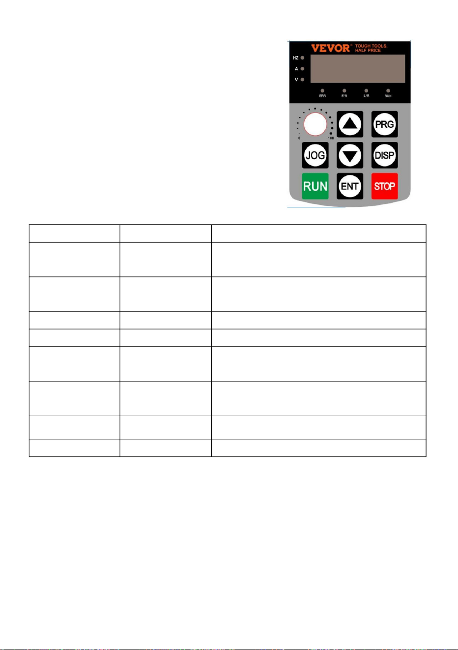
Begränsad till funktionskoden P08.01
Namn
ÿ Hz: Indikatorlampa för frekvensdisplay
Bestäm
visa innehållet
nyckel
Meny går in eller ut, med parameter
ÿ A: Strömindikatorlampa
driftläge
JOGGA
Skift-tangenten
1. Tryck på PRG -knappen för att visa P 0.00, 2. Knapparna
ÿ ÿ och DISP väljer parameternumret som ska ändras, och
ÿ F / R: Fram- och bakåtindikatorlampa
Ner-tangenten
Gå in i menyn och bekräfta
Beskrivning av funktionsindikatorlampa
PRG
nyckel
Ökning av data eller funktionskoder
ÿ RUN: Körindikatorlampa
ÿ
ÿ V: Spänningsindikatorlampa
Funktionsdeklaration
ÖNHN
Starta växelriktaren under tangentbordet
Kör nyckeln
Välj parametermodifieringsbiten och
Jogga nyckel
Övre nyckel
DISP
ÿ ERR: felindikatorlampa
modifiering
STOPP
3. ÿ ÿ och DISP- tangenterna ändrar parametervärden, ENTER- tangenten sparar parametrar, 4. Om du
behöver ändra andra parametrar, upprepa steg 2,3, såsom modifiering
ENTER -tangenten anger parametern,
ÿ L / R: Kontrollampa för kommunikation
parameterinställning
ÿ
SIKT
Programmering
Minskande data eller funktionskoder
Nyckelsymbol
Stopp/Återställ-knapp Stopp/återställningsfunktion,
slutförande, återgå till frekvensgränssnittet med PRG -tangenten.
- 8 -
Ställ in parametermetoden:
2. Drift och visning
Machine Translated by Google

- 9 -
3. Sammanfattningstabell över funktionella parametrar:
0,0V ~ 3000,0V
0 ~ 32767
0 ~ 100 kHz
P00.07
0 ~ 65535
-
P00.18
-
0,00 ~ 320,00 HzÿP01.22=2ÿ-
AI1 spänning (V)
linjär hastighet
PID-inställning
P00.22
0 ~ 65535m/min
-
-
räkna värde
0 ~ 32767
0,000V ~ 10,570V
Utström (A)
AI1 Spänning före korrigering
P00.00
-
Samlingsskena spänning (V)
0,00mA ~ 20,00mA
Återkopplingshastighet (Hz)
P00.25
-
Kommunikationsinställning
P00.06
P00.17
P00.10 AI2 Spänning (V) eller ström (mA)
-100,00 % ÿ 100,00 %
Ställ in frekvensen
-
Visning av lasthastighet
-
0.000mA ~ 20.000mA
-
Uteffekt (kW)
0 ~ 65535
0V ~ 1140V
-
-
P00.14
-
0 ~ 65535
P00.03
Pulsingångsfrekvens
P00.24
-
P00.21
OF ingångstillstånd
0,00V ~ 10,57V
0,0 ~ 6500,0 Min
0,0 ~ 3200,0 Hz (P01.22=1) -
0,0 ~ 6500,0 Min
korrektion
-
PLC-steg
0,00A–655,35A
0 ~ 65535
-
Aktuell körtid
P00.05
P00.16
P00.13
-
Utspänning (V)
P00, Övervakningsgrupp
0 ~ 1023
0 ~ 65535
P00.02
-3200.0Hz ~ 3200.0Hz
P00.09
-200,0 % ÿ 200,0 %
P00.28
P00.20
-
-
-
-
PID-feedback
-320,00 Hz ~ 320,00 Hz
P00.08
Utgående vridmoment (%)
-
Aktuell effekttid
0 ~ 65535
P00.04
P00.15
löpfrekvens
0,01V
0 ~ 6500 min
Körtid kvar
P00.26
Längdvärde
AI2 Spänning/ström före
DO-utgångstillstånd
-
0,000V ~ 10,570V
-
P00.19
-
P00.01
P00.12
Machine Translated by Google

P00.37
P00.42
-
-100,00 % ÿ 100,00 %
Växelriktartillstånd
modell)
P00.31
P00-59
läge
-
ÿ—inte modifierbar parameter under körstatus •—den
faktiska detekterade parametern, inte modifierbar
-
G/P typ
P00.44 Visuell display för DI-funktionsstatus 2
0V ~ Motorns märkspänning
P00.40 Utspänning av VF-separering
-
ändra
Målvridmoment, (%)
P00-61
P01.01
-
2: Typ P (fläkt och vattenpump
P00-60
-
P00.35
Ställ in räckvidd
1. Motorstyrning
-
ÿ—modifierbar parameter under alla förhållanden
IN-ingångsstatusdisplay
-
P00.39 Målspänning för VF-separering
P01 Grundläggande funktionsgrupp
kanal ("L/R" lyser släckt)
0,00 Hz ~ 500,00 Hz
-
2 ÿ
-
P01.00
DI-funktionsstatusdisplay 1
Löpfrekvens (%)
-
P00.32 Visa valfritt minnesadressvärde
-
FC
kommando
P00.41
0,0°ÿ 359,9°
P01.02
-
modell)
värde
0: Manöverpanelens körkommando
Effektfaktor Vinkel
Frekvens X Display
felmeddelande
0,00 Hz ~ 500,00 Hz
(Funktion 41. Funktion 80)-
-
0 ~ 65535
P00.43
Kontrollera
Fabrik
Drift
-
-100,00 % ÿ 100,00 %
DO-inmatningsstatusdisplay
0 ÿ
0 ~ 65535
-
1: Typ G (konstant vridmomentbelastning
Frekvens Y Display
Ställ in frekvensen på (%)
-
P00.30
2: V/F styrmodell
1 ÿ
P00-45
-
0V ~ Motorns märkspänning
0: Hastighetssensorlös vektor
(funktion 01. funktion 40)-
namn
- 10 -
Machine Translated by Google

P01.03
2: Kommunikationskommando
Begränsa urvalet av
Ensiffra: Val av frekvenskälla
P01.05
9: Kommunikationsset.
("L/R"-lampor blinkar)
1: Huvud- och sekundärdrift
00
1: Digital set (förinställd frekvens
P01.08, knappsats ÿ/ÿ knapp,
strömavbrottsminne)
Gräns för Y när
Samma som P01.03
(Huvudfrekvenskälla X ) inställd
1: Terminal Run-kanal ("L/R"
lyser)
4 ÿ
0: Jämfört med ÿP01.10ÿ Maximal
frekvens 1: Relativt till
frekvenskällan X
P01.04
Huvudfrekvens
P01.06
kanal
8: PID-kontrollset;
0 ÿ
0: Huvudfrekvenskälla X
frekvensöverlagring
Y när
frekvensöverlagring
P01.07 Frekvenskälla
0: Digital set (förinställd frekvens
P01.08, knappsats ÿ/ÿ knapp,
strömavbrott)
Sekundär
frekvenskälla
2: AI1 analog set (0-10V); 3:
AI2 analog set (0-10V eller
20mA);
4: Panelpotentiometer; 5:
Pulsuppsättning (0~50KHZ DI5);
6: Flerstegs
hastighetskörningssats 7: Enkel PLC-sats;
0 ÿ
100 % ÿ
OCH
0 % ~150 %
kanal
källa X
- 11 -
Machine Translated by Google

P01.12
källa
0,00 Hz ÿ
1:X-Y
Y-omkopplare för sekundär frekvens
Hz
Maximal utfrekvens
P01.08
Minimum av de två.
frekvens X och Main och
Hz
Övre
gränsfrekvensförspänning
ÿ
Hz
4: Frekvensen Y växlar med
P01.09 Löpriktning
Prepositionsfrekvens
2: Huvudfrekvens X och
0:X+Y
50.00
0: Konsekvent riktning, 1:
resultat
V/F:
3: Växla mellan huvud
2: Maximalt av de två,
ÿ
50.00
Övre
gränsfrekvens
2000,00 Hz
P01.11
0 ÿ
P01.10
Sekundära operationsresultat
3:
Övre
gränsfrekvens
50.00
ÿ
0.00Hz ÿÿP01.10ÿ
ÿP01.14ÿÿ ÿP01.10ÿ
P01.13
Huvud- och sekundärdrift
0.00Hz ÿ Maximal frekvens ÿP01.10ÿ
Vektor: 50.00Hz ~ 500.00Hz
0: ÿP01.12ÿ Setup 1: AI1
Setup 2ÿAl2
Setup 3: AI3
Setup 4: Puls
set (0~50KHZ DI5); 5:
Kommunikationsinställningar
Motsatt riktning
50,00 Hzÿ
resultat (driftsförhållandet bestäms av
tio siffror)
Tio siffror: Frekvensdriftsrelation
mellan X och Y
0 ÿ
- 12 -
Machine Translated by Google

0,5 kHz ~ 16,0 kHz
Accelerationstid
2: 0,01 sekunder
Val av
motorparametergrupp
0:1
0 ÿ
P01.15 Bärfrekvens
Retardationstid
0,00 Hz ÿ
Hänvisning
0: Motorparametergrupp 1,
1: Motorparametergrupp 2.
0,0s ÿ 6500,0sÿP01.19=1ÿ
Bias frekvens av
frekvens Y
när
1 ÿ
Stäng av
0 ÿ
För modell ÿ
Tidsenhet av
Digital
frekvensinställning
1: Ställa in frekvens
1
Frekvens
P01.14
Acceleration och
P01.21
0 ÿ
0: Nej, 1: Ja
retardationstid
Justera med
temperaturen
Körning
P01.19
2 ÿ
0: Inget minne 1: Minne
1
ReferensfrekvensÿP01.25ÿ
Upplösning av
0,00 Hz ÿ
1 ÿ
frekvens av
P01.16
1: 0,1 sekunder
minne för
0: Driftsfrekvens,
retardationstid
Bärvågsfrekvens
frekvens
0s ~ 65000sÿP01.19=0ÿ
sekunder
kommandon.
ÿ
P01.23
P01.17
UPP/NER
0: Maximal frekvensÿP01.10ÿ 1:
Inställningsfrekvens
2:100Hz
ÿ
0 ÿ
0,00s ~ 650,00sÿP01.19=2ÿ
Acceleration och
P01.22
frekvensinstruktion
0,00 Hz ÿÿP01.12ÿ
P01.18
superposition
Nedre gräns
För modell
P01.24
0.00Hz ÿ Maximal utfrekvens
ÿP01.10ÿ
P01.26
Upplösning av alla frekvenser
P01.25
- 13 -
Machine Translated by Google

(Invertereffekt > 55kW)
Av
P02.03
frekvenskälla
val av källa
urval
Märkspänning på
0: Vanlig asynkronmotor,
9: Kommunikationsuppsättning
1: Digital set
P02.01
P02.02
ÿ
ÿ
0,01A–655,35A
5: Pulsuppsättning (0~50KHZ DI5);
0 ÿ
P01.27
Ensiffrig: Bindningsfrekvens
för manöverpanelens kommando
buntade
Tusentalsiffror: Kör automatiskt
bindningsfrekvenskällan
urval
7: Enkel PLC
Motortyp
0: Ingen bindning
8:PID
P02 Asynkronmotor parametergrupp 1
Motor
ÿ
motor
Modell
1: Variabel frekvens
asynkronmotor
0,1kW ~ 400,0kW
2:AI1 3:AI2 4:AI3
0000 ÿ
Inverter
1V ~ 2000V
0,1A–6553,5A
Märkström av
(Invertereffekt <=55kW)
Motor
6: Flersegmenthastighet;
Tiosiffrig: Terminalkommando
bindningsfrekvenskälla
P02.00
Enligt
100 siffror: val av källa för
kommunikationskommando
bindande frekvens
Nominell effekt av
riktmärke
Kommandokälla
till
- 14 -
Machine Translated by Google

P03.00
motorn
30 ÿ
Statormotstånd
Nominell hastighet på
av Motor
P02.09
0,001Mh ~ 65,535mH
av motor
0,01Hzÿ Maximal utfrekvens
ÿP01.10ÿ
ÿ
0.1A ~ P02.03
(Invertereffekt > 55kW)
0 ÿ
P02.04
ÿ
Rotormotstånd
av motor
0,001ÿ ÿ 65,535ÿ (Invertereffekt
<=55kW) 0,0001ÿ ÿ
6,5535ÿ (Invertereffekt> 55kW) 0,001ÿ ÿ
65,535ÿ
(Invertereffekt <=05,000) 1ÿkW 6,5535ÿ
(växelriktareffekt>
55kW) 0,01mH ~ 655,35mH
Läckagemotstånd
ÿ
P02.05
P02.08
motor
P02.06
(Invertereffekt <=55kW)
av Motor
(Invertereffekt >
55kW) 0: ingen
funktion 1: Inställning vid
stillastående motor 1 2:
Dynamisk inställning av motor 3:
Inställning vid helt stillastående motor 2
Ömsesidigt motstånd
P02.10
Inställning
0,01mH ~ 655,35mH
ÿ
ÿ
ÿ
P02.37 Inställningsval
Hastighetsslinga
proportionell 1
1 ~ 100
P03 Vektorkontrollparametrar för motorgrupp1
ÿ
av Motor
Parameter
0.01A ÿ P02.03 (växelriktareffekt
<=55kW)
P02.07
(Invertereffekt> 55kW) 0,1mH
~ 6553,5mH (Invertereffekt <=55kW)
Nominell frekvens
1 rpm ~ 65535 rpm
Tom ström av
- 15 -
Machine Translated by Google

P03.02
20 ÿ
konstanter
Proportionell vinst på
P03.06
0,50 s ÿ
P03.05
4: Pulset (DI5);
P03.14
excitation
0.01s ~ 10.00s
hastighetskontroll
Integrationstid
för hastighetsslinga 2
0 ÿ
P03.15 Proportionell vinst
5.00Hz ÿ
100 % ÿ
kontrollläge
50 % ~ 200 %
7: MAX (AI1, AI2)
0.00 ÿ ÿP03.05ÿ
reglering
3: AI3;
Integral förstärkning
av excitation
1 ~ 100
0,000 s ~ 0,100 s
Hastighetsslinga proportionell 2
SVC-
momentfiltreringstid
150,0 % ÿ
0 ~ 60 000
P03.04
Vektorkontroll av
6: MIN (AI1, AI2)
0.01s ~ 10.00s
källa under
1300 ÿ
Växlingsfrekvens
P03.07
0,0 % ~ 200,0 %
0 ~ 60 000
1
Växlingsfrekvens
10.00Hz ÿ
skiftvinsten
Övre vridmomentgräns
under hastighet
Vridmoment övre gräns
P03.13
1.00s ÿ
0 ~ 60 000
0: P03.10 inställning 1ÿ
AI1; 2ÿAI2;
2000 ÿ
P03.03
0,050 s ÿ
P03.10
P03.01
2
5: Kommunikationsinställning;
Integrationstid
för hastighetsslinga 1
P03.02 ÿMaximal utfrekvens
ÿP01.10ÿ
reglering
läge
P03.09
2000 ÿ
- 16 -
Machine Translated by Google

6: Minskande vridmomentkurva
2 (1,6 effekt)
Inbyggd förstärkning
av vridmomentreglering
0,1 %–30,0 %
0,0 % ~ 100,0 %
50,00 Hz ÿ
10: VF helt separationsläge
P03.16
0,00 Hz ÿ
P04.06
P04 V/F-kontrollparametrar
P04.03
P04.00 VF-kurvans inställning
vridmomentreglering
4: Minskande vridmomentkurva
2 (1,4 effekt)
P04.01
Momentförstärkningsinställning Momentförstärkningsgränspunkt Flerpunkts V/F Frekv. 1 Flerpunkts V/F Spänning 1 Flerpunkts V/F Frekv. 2 Flerpunkts V/F-spänning 2
1: Flerpunktskurva V/F
2: Minskande vridmomentkurva
1 (kvadratkurva)
0,00 Hz ÿ
1300 ÿ
8: Minskande vridmomentkurva
2 (1,8 effekt)
0.00Hz ÿMaximal utfrekvens
ÿP01.10ÿ
ÿP04.03ÿ ÿ ÿP04.07ÿ
0,0 % ÿ
P04.04
P04.02
P04.05
0 ~ 60 000
0 ÿ
0: linjär kurva V/F
11: VF semi-separation läge 0,0%
(Automatiskt lyftmoment);
0.00Hz ÿ ÿP04.05ÿ
0,0 % ~ 100,0 %
Efter modell ÿ
0,0 % ÿ
av
3: Minskande vridmomentkurva
2 (1,2 effekt)
- 17 -
Machine Translated by Google

Spänning stadstid
för VF-separation
av VF-separation
0V ÿ Motorns märkspänning
P04.16
V/F över
frekvens ÿP02.04ÿ
0 ~ 100
Spänningskälla av
0: Digitala inställningar ÿP04.14ÿ
Svängning
P04.07
0 ÿ
Obs: Tid när 0V stiger till
0: Frekvensen och spänningsfallet
till 0 separat;
7: PID
0,0s ÿ
P04.08
2: AI2
undertryckande vinst
ÿP04.05ÿÿ Motorklassad
0,0 % ~ 200,0 %
0 ~ 200
Spänningsfall till 0 - 18 -
P04.17
64 ÿ
0,0 % ÿ
4: Pulsinställning (DI5)
0,00 Hz ÿ
excitationsvinst
Efter modell ÿ
VF separerade
Spänning för
VF-separering
6: Enkel PLC
P04.14
1:AI1
P04.13
0,0 % ÿ
P04.11
0,0s ~ 1000,0s
0V ÿ
motorns märkspänningÿ 0.0s
~ 1000.0s
0,0s ÿ
P04.15
Obs: Tid när märkspänningen för
motorn är 0V
1: Frekvensen faller efter
0,0 % ~ 100,0 %
för V/F
3: AI3
8: kommunikation
Inställning Obs: 100,0 %,
motsvarande motorns märkspänning
Avstängningsläge
0 ÿ
P04.10
5: Flera instruktioner
Flerpunkts V/F
Frekv.
3 Flerpunkts V/
F
Spänning 3 V/F-
kontroll
Slirfrekvenskompensation
P04.09
Spänningsökningstid
för VF-separation
Machine Translated by Google

50 % ~ 200 %
20 ÿ
1 ÿ
DI1 anslutning
760,0V ÿ
aktionsström
nuvarande stall
Maximal höjning
5: Omvänd jogkontroll (RJOG)
1
Ersättning
30 ÿ
ÿ
5Hz ÿ
150 % ÿ
Överspänningsstopp
aktionsspänning
Undertryckning av
överspänningsstoppssuppressions Frekv. förstärkning av överspänningsstopp Suppressions spänningsförstärkning av överspänningsstopp
2: Backkörning (REV) eller
50 % ÿ
0 ~ 50 Hz
Över nuvarande stall
0 ~ 100
3: tre-tråds körkontroll 4: framåt jog
kontroll (FJOG)
Suppressions
vinst av Over
P04.23
1: Aktivera.
650.0V ~ 800.0V
0: Ingen funktion;
P05.00
nuvarande stall
50 % ~ 200 %
Överspänningsstopp
P04.19
0 ~ 100
1
1: Aktivera.
Spring;
0: Inaktivera,
P04.18
handling över
P04.22
Grupp P05, Ingångsparametrar
P04.24
ÿ
0 ~ 100
30 ÿ
fungera
P04.20
0: Inaktivera,
1: Kör framåt (FWD) eller
Undertryckande av
P04.21
frekvensgräns för
Överströmsstopp
koefficient på
Omkopplare framåt/bakåt
P04.25
P04.26
- 19 -
Machine Translated by Google

10: Avbryt drift; 11: Externt
fel normalt öppen (NO) ingång 12: Multi-
speed 1 13:
Multi-speed 2 14: Multi-
speed 3 15: Multi-speed
4 16: ACC/DEC-tidsval
1( TT1)
20: Kör kommando Switch
31: Reserverad;
18: Frekvenskälla switch 19: UPP/
NER Frekv. nollrensning
(terminal, tangentbord)
27: Ingång för längdräkning
28: Längdåterställning
29: Vridmomentkontroll Avaktiverad
30: Pulsinställning (endast DI5-
burkinställning, P05.04=30)
22: PID-kontroll Paus
7: Frekv. minska(Terminal DOWN)
33: Extern felingång (normalt
6: Frekv. Öka (Terminal UPP)
terminal 1
21: VFD ACC/DEC förbjuder
9: Extern
återställningssignalingång (RST)
24: Pendelfrekvens Paus
32: DC-bromsning omedelbart;
8: Gratis avstängningskontroll
23: PLC-tillstånd återställs
17: ACC/DEC tidsval 2( TT2)
25: Räknarinmatning
26: Räknaren återställs
- 20 -
Machine Translated by Google

13 ÿ
43: Omkopplaren för PID-parametrar
Aktiverar
kontrollbrytare
fungera
DI2 terminal
45: Användardefinierat fel 2
36: Extern parkeringsterminal 1
4 ÿ
9 ÿ
terminal 2
DI3 terminal
47: Nödstopp
41: Motorvalsplint 1
34: Frekvensändring
51: Tvåtrådskontroll / Tretrådsstyrning
49: Långsamt åt DC-bromsning
39: Frekvens X växlar med den
förinställda frekvensen
DI4 terminal
35: PID-ingångssignal omvänd;
44: Användardefinierat fel 1
52: Återföring avaktiverad;
(endast DI5 kan
12 ÿ
DI5 terminal
P05.04
funktionell
P05.01
37: Kör kommando Switch
46: Hastighetskontroll /
Momentkontrollbrytare
38: PID-integral Paus;
48: Extern parkeringsterminal 2
funktionell
P05.02
50: Körtiden rensad;
funktionell
stängd, NC)
40: Frekvens Y växlar med den
förinställda frekvensen
P05.03
- 21 -
Machine Translated by Google

3: Tretrådskontrollläge 2.
Frekvens
P05.13 ÿ +10.00V
Motsvarande
P05.14
P05.10 DI-filtreringstid
kurva 1
-100,0 % ÿ +100,0 %
värdet på AI-kurvan
2:s min. input
0,001 Hz/s ~ 65,535 Hz/s
P05.16
Läge
P05.17
10,00V ÿ
2: Tretrådskontrollläge 1,
Motsvarande
input
0,00V ÿ P05.15
0,10s ÿ
1: Tvåtrådskontrollläge 2,
P05.18 ÿ +10.00V
100,0 % ÿ
Motsvarande
P05.11
kurva 1
Terminalstyrning
-100,0 % ÿ +100,0 %
0,0 % ÿ
P05.18
värdet på AI-kurvan
P05.12
P05.13
tid
0: Tvåtrådskontrollläge 1,
Motsvarande
-100,0 % ÿ +100,0 %
0 ÿ
1:s min. ingång
Max. ingång av AI
0,00V ÿ
P05.21
0,010s ÿ
funktion,
P05.04=30)
Min. ingång av AI
värdet på AI-kurvan
AI-kurva 2:s min.
P05.15
P05.19
1,00 Hz/s ÿ
2:a Max. input
10.00V ÿ
0,0 % ÿ
justeringssteg
-100,0 % ÿ +100,0 %
0.00V ~ P05.20
0.000 s ~ 1.000 s
0,00V ÿ
1:ans Max.
ingång AI-kurva 1 filtrering
inställning av puls
storlek
P05.20 Max. ingång för AI2
värdet på AI-kurvan
0.00s ~ 10.00s
100,0 % ÿ
- 22 -
Machine Translated by Google

P05.23
P05.24
P05.28
värdet av Pulse's
100,0 % ÿ
tid
Motsvarande
värdet av Pulse's
1: Jag har 1 horor
P05.32
P05.25
Motsvarande
Motsvarande
P05.23 ÿ +10.00V
(14.00, se P05.18 ~ P05.21.)
-10,00V ÿ
-100,0 % ÿ +100,0 %
P05.31
P05.26
-100,0 % ÿ +100,0 %
0.00s ~ 10.00s
2: Jag har 2 horor
P05.29
Enkelbit: Val av AI1-kurva
0,0 % ÿ
Min. värdet av
input
P05.33 Val av AI-kurva
P05.27
Pulsingång
tid
10,00V ÿ
3:or Max.
ingång AI kurva 3 filtrering
Max. värdet av
0,10s ÿ
Pulsingång
(14.00, se P05.13 ~ P05.16.)
värdet på AI-kurvan
tid
100,0 % ÿ
321 ÿ
-10.00V ÿ P05.25
P05.22
kurva 3
0,10s ÿ
P05.30
0,00V ÿ
Max.
ingång Pulsfiltrering
3:s min. ingång
Max. ingång av AI
0,10s ÿ
-10.00V ÿ P05.25
-100,0 % ÿ +100,0 %
-100,0 % ÿ +100,0 %
0.00s ~ 10.00s
Motsvarande
(14.00, se P05.23 ~ P05.26.)
AI-kurva 3:s min.
värdet på AI-kurvan
Min. input
AI-kurva 2-filtrering
P05.23 ÿ +10.00V
0.00s ~ 10.00s
0,0 % ÿ
10,00V ÿ
3: Jag har 3 horor
- 23 -
Machine Translated by Google

lägesval
minimum
5: Jag har horor 4
0,0s ~ 3600,0s
Enkel bit: DI1;
0,0s ~ 3600,0s
urval
Tio bitar: AI2 kurvval (samma som Single
bit 1~5)
Hundratals bitar: DI3;
Tio tusen bitar: DI5
P05.38
(samma som ovan)
0,0s ~ 3600,0s
P05.34
AI är nedan
(16.00, se P24.00–P24.07)
P05.37 DI3 fördröjningstid
P05.35 DI1 fördröjningstid
Tio bitar: AI2 under Min.
ingångsinställning (samma som Single bit 1~2)
DI1-DI5 terminal
(16.00, se P24.08–P24.15)
ingångsinställning
0,0s ÿ
Tio bitar: DI2;
0: Hög nivå effektiv, 1: Låg
lägesval
nivå effektiv
0,0s ÿ
Tusen bitar: DI4,
Hundra bitar: Val av AI3-kurva
000 ÿ
Enkelbit: DI6,
00 000 ÿ
P05.39
00 000 ÿ
Enkelbit: AI1 under Min.
ingångsinställning 0: Motsvarande
värde
på Min. ingång 1: 0,0 %
0,0s ÿ
0: Hög nivå effektiv, 1: Låg nivå effektiv
DI6-D17 terminal
P05.36 DI2 fördröjningstid
giltig
4: Jag har 4 horor
Hundra bitar: AI3 under Min.
ingångsinställning (samma som ovan)
giltig
- 24 -
Machine Translated by Google

7: Inverter överbelastning
DO1-utgång
(TA-TB-TC)
16:AI1>AI2
P06.02
8: The Set Count anländer
funktionsval
begränsa
19: Undertryckstillstånd utgång 20:
Kommunikationsinställning 21: Platsen
är klar (reserverad) - 25 -
3: Frekv. nivådetekteringssignal
1(P14T1)
Urval
9: Det angivna antalet har uppnåtts
0 ÿ
Grupp P06, utgångsparametrar
Relä
11: PLC-cykeln är klar
5: VFD
nollhastighetskörning (vid körning)
13: Frekvensbegränsning
P06.01
Tidig varning
2 ÿ
17: Utgångsfrekvens. når Övre
15: Redo att springa
Fungera
18: Utgångsfrekvens. når den nedre
gränsen (vid körning)
0: Ingen utgång
1: Driftindikator; 2:
Felutgång (för gratis avstängningsfel)
Kontrollstyrelsen
4: Frekvens
ankomstindikator (FAR)
10: Längden är uppnådd
anländer
12: Ackumulerad gångtid
14: Vridmomentbegränsning
Tio bitar: DI7
6: Motoröverbelastning Tidig varning
Machine Translated by Google

- 26 -
25: Frekv. nivådetekteringssignal
2(P14T2)
temperatur anländer
36: Utström utanför gräns
37:Utgångsfrekvens. når nedre
gräns (avstängning också utgång)
P06.07
35: Power-modulen
Val av AO2-
utgångsfunktion
23: Nollhastighetskörning 2
(utmatas även vid avstängning)
avstängningsfel och ingen under
P06.08
1 ÿ
22: Läge närhet (reserverad)
38: Felutgång (alla fel)
39: Motor överhettning
Tidig varning
40: Denna gångtid kommer
41: Felutgång (gratis
anländer
0: Driftsfrekv., 1:
Ställ in frekv.
0 ÿ
24: Ackumulerad starttid
tryckutgång)
26: Utgångsfrekvens. 1 nådde 27:
Utgångsfrekvens. 2 nådd 28:
utgångsström 1 nådd 29: utgångsström
2 nådd 30: regelbundet nådd 31:
ingångssignal Al1
överskridande 32: lastfall 33: VFD
går omvänd 34:
nollströmstillstånd
2: Utström, 3:
Utgående
vridmoment, 4:
Uteffekt, 5: Utspänning,
Val av AO1-
utgångsfunktion
Machine Translated by Google

- 27 -
14: Utgångsström. (100,0 %
i förhållande till motorstyrkan)
-10.00 ÿ +10.00
0,0s ~ 3600,0s
tid
8: AI2
AO2 noll-bias
0,0s ÿ
Tio bitar: RELÄ1
statusval
AO1 noll-bias
P06.13
Motsvarande 1000.0V)
RELA2 utgång
12: Kommunikationsinställning,
13: Motorhastighet
P06.17
P06.19
DO-utgångsfördröjning
fördröjningstid
11: Räknevärde
1.00 ÿ
P06.22
(Procentandel av verkligt värde
P06.11
15: Utspänning (100,0 %
P06.10
P06.18
DO-utgång giltig
i förhållande till VFD-betyg)
AO2 vinst
RELÄ-utgång
10: Längd
0,0 % ÿ
16: Motorns utgående vridmoment
1.00 ÿ
0,0s ÿ
Motsvarande 1000.0A)
7: AI1
AO1 vinst
0,0 % ÿ
0,0s ÿ
-100,0 % ÿ +100,0 %
Single Bit: GÖR
(Procentandel av verkligt värde
P06.12
0: Positiv logik, 1: Antilogik
17: VFD utgående vridmoment
-100,0 % ÿ +100,0 %
0,0s ~ 3600,0s
9: AI3
koefficient
0,0s ~ 3600,0s
6: Ingångspulsfrekvens.
koefficient
00 000 ÿ
-10.00 ÿ +10.00
fördröjningstid
Machine Translated by Google

- 28 -
0: Börja med avstängningen
P07.01
0 % ÿ
segment i S
P07.05
0: Direktstart
0,00 Hz ÿ
Accelererande
30,0 % ÿ
segment i S
Speed of Speed
spårning
P07.06
Hastighetsspårning
2: S-kurva Acc/Dec-läge B
P07.00 Startläge
DC-bromsström
P07.08
håll tid
1: S-kurva Acc/Dec-läge A
0 ÿ
uppstart
30,0 % ÿ
0 ÿ
0 % ~100 %
1: Börja med arbetsfrekvensen
0,0s ÿ
Inbromsande
läge
P07.09
1 ~ 100
Start-frekvens
0: linjärt Acc/Dec-läge
2: DC-bromsning + start vid
startfrekvens
0,0s ÿ
metod
0,0s ~ 100,0s
0.0%ÿÿ100.0%-P07.09ÿ
frekvens
P07 grupp, start- och stoppkontrollparametrar
P07.02
0,00 Hz–10,00 Hz
P07.07
DC-bromstid kl
Tidsförhållande för start
frekvens
kurva
vid uppstart
kurva
2: Börja på max
P07.04
Tidsförhållande för start
1: Börja med hastighetsspårning
P07.03 Startfrekvens
och
Hundra bitar: RELÄ2
20 ÿ
0.0%ÿÿ100.0%-P07.08ÿ
0,0s ~100,0s
0 ÿ
Machine Translated by Google

- 29 -
tröskel för DC
0,0s ÿ
ÿ
giltig
0,0s ÿ
ÿP01.10ÿ
stopp
P08.01 M nyckelfunktion
P08.03
Bit00: Körfrekvens 1 (Hz)
P07.13 DC-bromsström
0: M-nyckeln är ogiltig
tid
4: RJOG (omvänd jogkontroll)
Frekvens
nuvarande
1 ÿ
Hastighetsspårning
3: FJOG (joggning framåt)
Stoppläge
Kontroll (terminal eller
kommunikationskontroll) och
manöverpanelskontroll, när
ÿP01.02ÿ =1 eller 2
Bit02: Bussspänning (V)
P07.11
P07.15
DC-bromsfördröjning
0,0s ~ 100,0s
STOPP/ÅTERSTÄLL
Driftstatus
0 % ÿ
utnyttjandegrad
2: FWD/REV-omkopplare
P07.10
P08 Grupptangentbord och skärmparametrar
0,00 Hz ÿ
100 % ÿ
P08.02
broms
0.00Hz ~ Maximal frekvens.
DC-bromstid kl
P07.14
1: STOP/RES-knappen Alltid
30 % ~ 200 %
LED visar
parameter 1in
0,0s ~ 100,0s
1F ÿ
P07.18
0000ÿFFFF
P07.12
0 % ~ 100 %
nyckelfunktion
0 ÿ
DC-broms
0 ÿ
0ÿBrota till stopp 1ÿUtrullning till
stopp
0 % ~ 100 %
Bit01: Ställa in frekvens (Hz)
1: Växla mellan fjärrkontroll
0: STOP/RES-tangenten Gäller
endast i panelstyrningsläge
Machine Translated by Google

- 30 -
Bit14: Visning av lasthastighet
Bit05: Uteffekt (kW)
(V)
P08.04
(V)
0000ÿFFFF
Bit07: DI-ingångsstatus
(Timme)
Bit11:PULSE Ingångsfrekvens
Bit09: AI1-spänning (V)
(V)
Bit01: PLC-steg
Bit04: Utström (A)
Bit13: Längdvärde
Bit05:AI1-korrigerad frontspänning
Bit03: Körfrekvens 2 (Hz)
Bit11: AI3-spänning (V)
LED visar
parameter 2in
Bit06: Utgående vridmoment (%)
Bit15: PID-inställningar
Bit06:AI2-korrigerad frontspänning
Bit09: Aktuell effekttid
Bit12: Kommunikationsinställning
0 ÿ
Bit07:AI3-korrigerad frontspänning
Bit10: Aktuell körtid (min)
Bit08: DO-utgångsstatus
Bit00: PID-återkoppling
Bit10: AI2-spänning (V)
Bit02: PULSE Ingångsfrekvens (kHz)
Bit08: Linjehastighet
(Hz)
Bit04: Återstående körtid
Driftstatus
Bit03: Utspänning (V)
Bit12: Räknevärde
Värde
Machine Translated by Google

- 31 -
0h ~ 65535h
Jogga Acc tid
0,0 ÿ ~ 100,0 ÿ
-
Bit04: AI1-spänning (V)
Bit14: Huvudfrekvens X Display
(kHz)
P08.06
parameter i Stopp
Bit06: AI3-spänning (V)
Bit15: Sekundär frekvens Y
Strömmodul
-
ÿP01.10ÿ
P08.08 Produktnummer
-
0000ÿFFFF
33 ÿ
Bit08: Längdvärde
(Hz)
Bit03: DO-utgångsstatus
Bit12: PULSE Ingångsfrekvens
P09.00 Joggfrekvens
P09.01
Bit10: Lasthastighet
Bit01: Bussspänning (V)
Lasthastighet
(Hz)
Bit05: AI2-spänning (V)LED-displayer
0,0001 ~ 6,5000
körtid
1 0000 ÿ
P08.07
status
temperatur
Display (Hz)
Bit07: Räknevärde
•
•
P08.09
•
-
0.00Hz ~ Maximal frekvens.
2.00Hz ÿ
Bit00: Ställ in frekvens (Hz)
Bit09: PLC-steg
P08.05
Kumulativ
20.0s ÿ
0,0s ~ 6500,0s
Bit11: PID-inställningar
visningsfaktor
Bit13: Kodaråterkopplingshastighet
Bit02: DI-ingångsstatus
P09 grupp, hjälpfunktion
Machine Translated by Google

- 32 -
P09.03
2
Omvänd död
0,0s ÿ
4
frekv.
0,4–4,0KW
Accelerationstid
0h ÿ
ÿ
P09.13
Förbjuda
0,00 Hz–10,00 Hz
Retardationstid
P09.02
Retardationstid
ÿ
0: Kör med en nedre gränsfrekvens
15.0S
P09.08
0,01Hz ÿ
den nedre gränsen för
Retardationstid
ÿ
5,5–30,0KW
När inställningen
kumulativ kraft
ÿ
0 ÿ
P09.04
Positivt och
37.0 ~ 132.0KW 40.0S
2: nollhastighetsdrift
P09.10 Hoppfrekv. 2
ÿP01.10ÿ
vid ankomsttid
0: Tillåtet;
P09.15
3
4
ÿ
Accelerationstid
20.0s ÿ
tillstånd
0h ~ 65000h
160.0–630.0KW 60.0S
räckvidd
P09.11
P09.14
1: Stopp
2
Jogga dec tid
3
P09.09 Hoppfrekv. 1
0.00Hz ~ Maximal frekvens.
Motsatt
0,0s ~ 3000,0s
P09.05
0,00 Hz ÿ
frekvens
P09.16
tid
P09.12
Accelerationstid
Hopp frekv.
0,00 Hz ÿ
0 ÿ
7,5S
P09.07
15,0
Rekommenderad tid:
Miljö
P09.06
1:
ÿ
Släpp kontroll
0,00 Hz ÿ
frekv. är lägre än
Machine Translated by Google

- 33 -
0 ÿ
50.00
0: Ogiltig, 1: giltig
0 ÿ
når
P09.30
0h ÿ
0,0 % ~ 100,0 % (P14T1-nivå)
P09.26
detektionsvärde 2
Hz
Frekvensdetekteringsfördröjningsvärde (P14T1)
accelerationstid
detektionsvärde 1
ÿP01.10ÿ
Godtycklig
ankomstfrekvens
0: Oskyddad;
P09.21
Frekvens
ÿ
0,0 % ÿ
0.00Hz ~ Maximal frekvens.
löpande
ankomst P09.18 Startskydd
Frekvensdetekteringsfördröjningsvärde (P14T2)
Växlingsfrekv. av
P09.28
ÿP01.10ÿ
P09.22
P09.19
5,0 % ÿ
Frekvenshoppningsfunktion
0,00 Hz ÿ
50.00
(P14T1)
0,0 % ~ 100,0 % (Maximal
frekvens)
1 och tid 2
0h ~ 65000h
P09.25
(P14T2)
0.00Hz ~ Maximal frekvens.
0 ÿ
Terminal Jog-
prioritet
Hz
0,0 % ~ 100,0 % (P14T2-nivå)
Frekvens
kumulativ
P09.20
upptäckt bredd
ÿP01.10ÿ
Växlingsfrekv. av
0: Ogiltig, 1: giltig
ÿ
0.00Hz ~ Maximal frekvens
dec.
P09.27
Hz
Under Acc och
0,00 Hz ÿ
50.00
P09.17
5,0 % ÿ
retardationstid
Miljö
Frekvens
ÿ
1 och tid 2
0.00Hz ~ Maximal frekvens
0.00Hz ~ Maximal frekvens.
P09.29
Machine Translated by Google

- 34 -
Hz
0,0 % ~ 100,0 % (Maximal
frekvens)
0,0 % (upptäcker inte)
Godtycklig ankomst
Nuvarande värde på
0,0 % ~ 100,0 % (Maximal
frekvens)
5,0 % ÿ
P09.37
0,0 % ÿ
Timer funktion
0,0 % ~ 300,0 %
Fördröjningstid på
0.00Hz ~ Maximal frekvens
0,0 % ~ 300,0 % (motorns
märkström)
0,0 % ÿ
50.00
Aktuell detektera
nuvarande 1 bredd
0: P09.44 inställning,
Fördröjningstid på
Godtycklig
ankomstström 1
Godtycklig
ankomstfrekvens
0,0 % ~ 300,0 % (motorns
märkström)
0.00s ÿ
P09.39
Godtycklig
ankomstfrekvens
0,01s ~ 600,00s
P09.32
P09.42
nuvarande
100,0 % ÿ
nuvarande 2 bredd
upptäckt bredd 2
100,0 % motsvarar motorns
märkström
aktuell detektion
P09.31
P09.36
P09.40
detektionsvärde 2
P09.35
Godtycklig ankomst
P09.43 Timer körtid
0 ÿ
ÿ
Godtycklig
ankomstfrekvens detekterad bredd 1
detektionsnivå
utgång över
0,0 % ~ 300,0 % (motorns
märkström)
200,0 % ÿ
Godtycklig ankomst
0,0 % ÿ
100,0 % ÿ
0,1 % ~ 300,0 % (motorns
märkström)
nuvarande 2
P09.33
0,10s ÿ
P09.38
0: Ogiltig, 1: giltig
0,0 % ÿ
P09.34
0,00s ~ 600,00s
detektionsvärde 1
Nollström
urval
Utgång över
0 ÿ
0,0 % ~ 300,0 % (motorns
märkström)
P09.41
Machine Translated by Google

- 35 -
Korrigeringsfaktor
P09.51 Sömnfrekvens
av uteffekt
3,10V ÿ
2: AI2
P09.47
Vakna försening
1: Kör alltid när ström
0.00V ~ P09.46
Analogt ingångsområde motsvarar
ÿP09.44ÿ
0,00 Hz ÿ
0,0s ~ 6500,0s
0,0s ÿ
0,0s ÿ
Ankomsttid för detta
tid
kontrollera
6,80V ÿ
1:AI1
AI1 ingångsspänning
skyddsvärde nedre
gräns
75ÿ ÿ
0,0 min ÿ
0,00 % ~ 200,0 %
P09.45 ~ 10.00V
0,0 min ~ 6500,0 min
P09.48
3: AI3
P09.45
0: Fläkten går under VDF-drift
Vilolägesfrekvens (P09.51) ~
Maximal frekvens.ÿP01.10ÿ
0,0s ~ 6500,0s
Vakna
frekvens
0,00 Hz ~ Wake-Up Frequency
ÿP09.49ÿ
Kylfläkt
P09.49
Timer igång
AI1 ingångsspänning
skyddsvärde övre
gräns Över
temp.
skyddsvärde
0,00 Hz ÿ
P09.52 Fördröjningstid för sömn
drift
P09.54
P09.53
P10 grupp Fel och skydd
0,0 ~ 6500,0 Min
P09.44
P09.46
0 ÿ
P09.50
100,0 % ÿ
0ÿ ~ 100 ÿ
på;
urval
0,0 min ÿ
tid
Machine Translated by Google

- 36 -
1
80 % ÿ
återställa
0: Inaktivera,
startspänning
typ
Motor överbelastning
1: Aktivera
0 ~ 20
11 ÿ
Tio bitar: Indragningsskydd
för kraftrelä
Kortslutning till
690V ÿ
0.20 ~ 10.00
1: Action
0: Inget fel
P10,00
Bromsenheter
Single Bit: Ingångsfasförlustskydd
Första gången misslyckande
1 ÿ
0: Ingen åtgärd
ÿ
1: Aktivera
650.0V ~ 800.0V
P10.12
Motor överbelastning
automatiskt fel
P10.01
ÿ
återställa tider
1,0s ÿ
Indragningsskydd
för kraftrelä
–
faktor
jordskydd när
strömmen är på
P10.09
1: Aktivera
återställa
0: Inaktivera,
skyddsvinst
urval under
0,1 s ~ 100,0 s
1
Utgångsfasförlustskydd
1.00 ÿ
skydd
0: Inaktivera,
Automatiskt fel
P10.10
Automatiskt fel
Ingångsfasförlustskydd/
tidig varning
•
1: Aktivera
Intervall för
1: Aktivera
P10.02
GÖR åtgärd
P10.11
P10.13
0: Inaktivera,
P10.07
0 ÿ
Motor överbelastning
50 ~ 100 %
0: Inaktivera,
P10.08
P10.14
0 ÿ
1: (Reserverad)
Machine Translated by Google

- 37 -
40: Timeout för snabb flödesgräns
7: Överspänning i konstant hastighet
2: Överström i Acc-processen
16: Kommunikationsundantag
undantag
Tredje
(senaste) feltypen
9: Underspänning
4: Överström i konstant
23: Motorkortslutning till jord
42: Hastighetsavvikelsen är för stor
27: Användaranpassat fel 1
•
•
11: Motor överbelastning
typ
6: Överspänning i decemberprocessen
15: Externt fel
13: Utgångsfasförlust
hastighet
18: Onormal strömdetektering
3: Överström i decemberprocessen
8: Buffertmotstånd överbelastning
17: Strömreläet är onormalt
22: Annan hårdvara onormal
29: Starttiden kommer
21: Parameterläsa och skriva
31: Runtime PID-återkoppling går förlorad
P10.16
26: Run-time ankomst
P10.15
10: VFD överbelastning
41: Växla motorn under drift
–
12: Ingångsfasförlust
–
28: Användaranpassat fel 2
14: Strömmodulen är överhettad
19: Motorinställningen är onormal
Andra misslyckandet
5: Överspänning i Acc-process
30: Lastfall
Machine Translated by Google

- 38 -
P10.18
–
Starttid för
tredje
(senaste) misslyckandet
fel
Aktuell vid
(senast)
–
–
–
–
P10.21
Ingångsterminal
P10.23
andra misslyckandet
–
(senast)
P10.24
status på trean
–
–
Aktuell vid
–
•
–
fel
Bussspänning vid
det tredje
(senaste) felet
–
status på trean
–
–
–
Utgångsterminal
–
•
–
andra misslyckandet
•
(senast)
Körtid för
•
tredje
(senaste) felet
Frekvens vid det
tredje
(senaste) felet
P10,20
Invertern
•
–
•
•
–
•
Frekvens vid
P10.19
P10.22
–
–
P10.17
fel
•
43: Motor överhastighet
status på trean
P10.27
•
det tredje
(senaste) misslyckandet
P10.28
Machine Translated by Google

- 39 -
status vid
P10.33
P10.31
–
–
–
–
andra felet
första misslyckandet
P10,43
–
Ingångsterminal
•
P10.42
andra misslyckandet
P10.32
status vid
•
•
Utgångsterminal
•
–
–
•
–
fel
–
andra misslyckandet
fel
Starttid för
–
–
Starttid för
–
Invertern
Utgångsterminalens
status vid den första
–
P10.30
•
–
P10,39
status först
P10,34
P10,38
–
status för
–
status först
•
andra misslyckandet
–
•
–
•
–
–
andra misslyckandet
P10,29
P10,37
–
–
–
Bussspänning vid
första felet
Körtid för
Invertern
P10,40
det första misslyckandet
•
–
det andra misslyckandet
P10.44 Körtid för
•
–
P10.41
Ingångsterminal
Aktuell vid första
•
Bussspänning vid
•
fel
Frekvens vid
–
•
fel
–
–
Machine Translated by Google

- 40 -
00 000 ÿ
Tio bitar: Ingångsfasförlust, (Err12)
Tio tusen bitar: Run-time
handling
P10,48
Kommunikationsundantag,
(Err16)
(Err13)
anländer (Err29)
0: Coast to stop; 1:
Stop by Stop-lägeÿP07.10ÿ 2: Hoppa
till 7% av den nominella frekvensen.
av motorn och fortsätt att gå, Kör
tillbaka till inställd frekv. när
(Err15)
0: Coast to stop; 1:
Stop by Stop-lägeÿP07.10ÿ Single
Bit: User Custom fel 1 (Err27)
Tio bitar: Parameterläs och
Enkelbit: Motoröverbelastning (Err11)
urval 1
skriv undantag (Err21)
handling
Felskydd
(Err28)
Hundra bitar: Utgångsfasförlust,
P10,47
00 000 ÿ
urval 3
P10,49
Felskydd
ankomst (Err26)
Tusen bitar: Lastfall (Err30)
Tusen bitar: Externt fel
0: Coast to stop; 1:
Stopp vid stopplägeÿP07.10ÿ 2:
Fortsätt köra;
Enkelbitar/hundrabitar/tusenbitar:
(Reserverad)
Tio tusen bitar:
Felskydd
Ten Bit:: Användaranpassat fel 2
00 000 ÿ
urval 2
Hundra bitar: Starttid
första misslyckandet
handling
Machine Translated by Google

- 41 -
Fortsätt köra
frekv. val vid fel
förlust (Err31)
0: Ogiltig
Spänningsåtervinning
1: Minska
P10,54
Tio bitar: Motoröverfart (Err43)
Omedelbar kraft
90,0 % ÿ
Tusen bitar:
hastighetsåterkopplingsfel (Err52)
0 ÿ
Onormal reserv
Tio tusen bitar: PID-feedback
P10,50
Omedelbar kraft
utan avbrott
frekvens
Val av felskyddsåtgärd
4
Pausen
0: Coast to stop;
1: Stopp vid stopplägeÿP07.10ÿ
2: Fortsätt köra;
Enkelbit: Hastighetsavvikelsen
för stor (Err42)
0 ÿ
hastighet;
Domstid för
0,00s ~ 100,00s
bedömningsspänning
för Instant power
non-stop
2: Retardationsstopp
P10,60
Hundra bitar: (Reserverad)
frekvens
0,0%~100,0% (100,0%
motsvarar Max frekv ÿP01.10ÿ
0: Coast to stop; 1:
Stopp vid stopplägeÿP07.10ÿ 2: Fortsätt
köra; 0: Aktuell
frekvens 1: Inställningsfrekvens
2: Kör vid övre gränsfrekvens
3: Kör vid nedre gränsfrekvens 4: Kör
vid onormal reserv
P10,55
P10,59
P10,61
100,0 % ÿ
80,0 % ÿ 100,0 % (Standard
bussspänning)
belastningsåtervinning
00 000 ÿ
0,50 s ÿ
Machine Translated by Google

- 42 -
0 ~ 100
P10,72
Lastfall
stor
P10,63
Vinst av Instant
Lastfallsskydd
0,0 % ~ 50,0 % (Max
frekv ÿP01.10ÿ)
P10,69
stor
20.0s ÿ
P10,65
Väsentlig
0,0s: Ej detekterbar
P10,71
0 ÿ
avvikelse också
1: giltig
Tid för upptäckt
av överhastighet
P10,62
0,0s: 0,1 ~ 60,0s
1,0s ÿ
20,0 % ÿ
P10,64
30 ÿ
ström non-stop
Nivå för
detektering av belastningsfall
P10,68
avvikelse också
Retardationstid
0: Ogiltig,
P10,67
80,0 % ÿ
detektionsvärde
P10,70
koefficient på
10,0 % ÿ
värde för Speed
40 ÿ
Bedömningsspänningen för Instant power non-stop
av Instant power
non-stop
urval
1,0s ÿ
Överhastighet
dags för Speed
Omedelbar kraft
utan avbrott
5,0s ÿ
upptäcktstid
Detektionen
0 ~ 100
0,0 ~ 100,0ÿ
Detektionen
20,0 % ÿ
60,0 % ~ 100,0 % (Standard
bussspänning)
0 ~ 300,0s
nonstop
P10,73
0,0–60,0s
0,0 % ~ 50,0 % (Max
frekv ÿP01.10ÿ)
0,1–60,0s
Machine Translated by Google

- 43 -
4: Pulsinställning (DI5)
0,0–10,00
P11.03
Tdl
8ÿMIN ÿ|AI1|, |AI2|ÿ
1: AI1
kanal
10.00 ÿ
0.000 s ~ 10.000 s
avvikelse
2: AI3
Proportionell vinst
7: Inställningar för tangentbordskodare
0,0 ~ 100,0
0,0 % ~ 100,0 %
P11.00 PID-ingångskanal
7ÿMAXÿ|AI1|, |AI2|ÿ
Derivattid
6: AI1+AI2
P11.05
0 ÿ
0,00 ~ Maximal frekvens
0 ÿ
P11.07
0 ~ 100,00 kg
P11.01
6: Flerstegshastighet
P11.02
P11.06
Gränsen för PID
1: AI2
5: Kommunikationsinställning
20.0 ÿ
3: AI3
feed-back
P11.08
Digital
referensingångsinställning
1: Negativ riktning
14.00 ÿ
P11.09
5: Kommunikationsinställning
0: P11.01 inställning
PID-feedback
0 ÿ
Ti1
Omfång av PID
cutoff frekv
3.00 ÿ
2.00Hz ÿ
PID-polaritet
PID-omkastning
0: AI1
0: Positiv riktning,
0.01s ~ 10.00s
P11.04
2: AI2
4: Pulsinställning (DI5)
P11 grupp PID funktion
3: AI1-AI2
KP02
0.000-tal ÿ
Integrationstid
1,0 % ÿ
Machine Translated by Google

- 44 -
P11.11
filtreringstid
P11.17
parameterväxling
14.00 ÿ
av PID
P11.15
parameterväxling
0,0 % ~ 100,0 %
Avvikelse 2
P11.13
2: Automatisk omkoppling enl
0.00 ~ 60.00s
PID
P11.22
0.00s ÿ
Ti2
PID
produktion
Integrationstid
villkor
Ändringstid för PID-
ingångssignal
0.00s ÿ
0.000-tal ÿ
P11.21 Initialt värde för PID
PID
P11.12
PID-feedback
1,00 % ÿ
0.01s ~ 10.00s
20,0 % ÿ
80,0 % ÿ
0.00s ÿ
KP03
P11.18
0,00 % ~ 100,00 %
1: Omkoppling via DI-terminalen
PID initial
0.00s ÿ
Td2
Avvikelse 1
0,00 % ~ 100,00 %
Max positiv
avvikelse på två
0,00 ~ 650,00s
P11.10
20.0 ÿ
P11.16
0,0 % ÿ P11,20
0: Ingen switch
P11,19 ~ 100,0 %
Proportionell vinst
Hålltid för
0.000 s ~ 10.000 s
P11.20
PID-utgångens
filtreringstid
Derivattid
P11.19
P11.23
0 ÿ
0,10 % ÿ
0,0 ~ 100,0
Differentialbegränsare
0.00 ~ 60.00s
avvikelsen
0,0 % ÿ
parameterväxling
0,00 ~ 650,00s
Machine Translated by Google

- 45 -
0: Ogiltig, 1: giltig
P11.25
0,0s ÿ
0,0 % ÿ
stängning
produktion
värden
Läge för Swing
freq inställning
P12.04
P12.03
(0,0 %:
1: Stopp med PID-drift
0: Fortsätt integrerad reglering,
Cykel av
svängningsfrekvens
Single Bit: Integral separation
PID
0,0 % ~ 100,0 %
tid
Räckvidden för
hoppfrekvensen
0,00 % ~ 100,00 %
0 ÿ
50,0 % ÿ
P11.26
00 ÿ
PID-integralegenskapen
P12 grupp - Svängfrekvens, Fast längd och Räkning
0 ÿ
10,0s ÿ
Ej upptäckt)
förlustdetektering
Omfång för
svängningsfrekvens
P11.24
0: Stopp utan PID-drift,
0,1 % ~ 100,0 %
1: Stoppa integrerad reglering
0,0 % ÿ
P12.01
Tio bitar: när frekvensen
avvikelse på två
förlustdetektering
drift
P12.00
0,0s ~ 20,0s
0,0 % ~ 50,0 %
0,1 % ~ 100,0 %
swing freqs
triangulära våg
P11.27
P12.02
når gränserna
0: I förhållande till centralen
0,0 % ÿ
frekvensÿP01.07ÿ 1:
Relativt till maxfrekvensen
ÿP01.10ÿ
1,00 % ÿ
PID-feedback
Max avvikelse
PID-feedback
P11.28
0,1s ~ 3000,0s
Uppgångstid för
Machine Translated by Google

0m ~ 65535m
1000 ÿ
4 (MS4)
P13.02
1 (MS1)
P12.05
1000 ÿ
Flerstegshastighet
P13.05
P13.04
Anger Count värde
6 (MS6)
100,0 ÿ
Flerstegshastighet
P13.07
P12.06
Flerstegshastighet
0,0 % ÿ
P13.10
0 (MS0)
9 (MS9)
0m ~ 65535m
0,0 % ÿ
7 (MS7)
0,0 % ÿ
Flerstegshastighet
0,1 ~ 6553,5
Inställningsräkning
P13.09
2 (MS2)
P13.00
0,0 % ÿ
värde
Flerstegshastighet
Flerstegshastighet
Verklig längd
Flerstegshastighet
0,0 % ÿ
P12.07
3 (MS3)
P13.01
0,0 % ÿ
P13.08
Antal pulser per
meter
0m ÿ
1 ~ 65535
Flerstegshastighet
0,0 % ÿ
5 (MS5)
0,0 % ÿ
1 ~ 65535
P13.06
Flerstegshastighet
P13.03
P12.08
Flerstegshastighet
0,0 % ÿ
0,0 % ÿ
8 (MS8)
Inställningslängd
P13 grupp Flerstegshastighet, enkel PLC
1000m ÿ
P12.09
Flerstegshastighet
-100,0 % ÿ 100,0 % (Maxfrekvens
ÿP01.10ÿ)
10 (MS10)
0,0 % ÿ
- 46 -
Machine Translated by Google

14 (MS14)
P13.12
0: Spara inte
0 ÿ
Enkelt PLC-
driftläge
0 ~ 3
Flerstegshastighet
0: Slut på enstaka operation
MS 0
0 ~ 3
0,0s (h) ÿ
P13.14
P13.18
0,0 % ÿ
MS 1
P13.23
Flerstegshastighet
Tio bitar: när Stopp
MS 2
P13.25 Acc/Dec tid för
Single Bit: när Power faller
Acc/Dec tid för
13 (MS13)
0 ÿ
Acc/Dec tid för
P13.21
P13.17
0,0 % ÿ
15 (MS15)
0.0sÿhÿ ~ 6553.5sÿhÿ
P13.16
0.0sÿhÿ ~ 6553.5sÿhÿ
0.0sÿhÿÿ 6553.5sÿhÿ
0,0 % ÿ
2: Cykla alltid
1 körtid
Flerstegshastighet
Flerstegshastighet 0
körtid
0,0s (h) ÿ
P13.11
00 ÿ
Acc/Dec tid för
P13.24
Flerstegshastighet 3
körtid
Flerstegshastighet
11 (MS11)
P13.15
0 ÿ
P13.22
0.0sÿhÿÿ6553.5sÿhÿ
0 ~ 3
P13.13
0 ÿ
1: Spara.
P13.19
0,0 % ÿ
PLC kör tillstånd
sparas efter
strömavstängning
2 körtid
0,0s (h) ÿ
Flerstegshastighet
12 (MS12)
1: Slutvärde vid slutet av enstaka
operation
Flerstegshastighet
0,0 % ÿ
0,0s (h) ÿ
P13.20
0 ÿ
Flerstegshastighet
0 ~ 3
- 47 -
Machine Translated by Google

0,0s (h) ÿ
0.0sÿhÿ ~ 6553.5sÿhÿ
0,0s (h) ÿ
Acc/Dec tid för
0.0sÿhÿ ~ 6553.5sÿhÿ
11 körtid
P13,26
6 körtid
P13,40
P13.33
0 ÿ
0 ÿ
0 ~ 3
MS 5
P13.31
0 ~ 3
0,0s (h) ÿ
P13,38
MS 4
P13.32
9 körtid
Flerstegshastighet
Flerstegshastighet
0.0sÿhÿ ~ 6553.5sÿhÿ
Acc/Dec tid för
Flerstegshastighet
10 körtid
0,0s (h) ÿ
0 ÿ
0.0sÿhÿ ~6553.5sÿhÿ
0 ~ 3
P13.28
P13,27
Acc/Dec tid för
Acc/Dec tid för
MS 8
0 ~ 3
0 ~ 3
0 ÿ
P13,29
MS 6
Flerstegshastighet 8
körtid
4 körtid
0 ÿ
0 ~ 3
P13,41
Flerstegshastighet 5
körtid
0 ÿ
P13,36
MS 10
0,0s (h) ÿ
0 ÿ
Flerstegshastighet
0.0sÿhÿ ~ 6553.5sÿhÿ
7 körtid
Acc/Dec tid för
0 ~ 3
P13.35
Acc/Dec tid för
MS 11
P13,37
0 ÿ
P13.30
MS 9
0,0s (h) ÿ
MS 7
Flerstegshastighet
P13,39
0 ~ 3
0.0sÿhÿ ~ 6553.5sÿhÿ
Acc/Dec tid för
MS 3
0.0sÿhÿÿ6553.5sÿhÿ
Flerstegshastighet
0,0s (h) ÿ
0,0s (h) ÿ
Acc/Dec tid för
P13,34
0.0sÿhÿ ~ 6553.5sÿhÿ
- 48 -
Machine Translated by Google

0 ÿ
P13,44
P13,46
5: PID
15 körtid
0.0sÿhÿ ~ 6553.5sÿhÿ
Acc/Dec tid för
0 ~ 3
P14 grupp RS485 Kommunikationsparametrar
6: Prepositionsfrekvens
ÿP01.08ÿ
7: Kan modifieras med ÿ/ÿ-tangenten
Flerstegshastighet
0,0s (h) ÿ
Flerstegshastighet 3
körtid
P13,50
4:4800BPS 5:9600BPS
0,0s (h) ÿ
0.0sÿhÿ ~ 6553.5sÿhÿ
4: Puls (DI5)
P13,48
0 ÿ
MS 12
2:1200BPS 3:2400BPS
P13,49
P13,51
0,0s (h) ÿ
0,0s (h) ÿ
0 ~ 3
Baudhastighetsinställning
för RS485
MS 15
1: AI1
0 (MS0)
MS 3
Flerstegshastighet
0: s (sekunder)
1: h (timmar)
Acc/Dec tid för
0 ~ 3
0:300BPS 1:600BPS
0.0sÿhÿ ~ 6553.5sÿhÿ
0 ~ 3
3: AI3
P14.00
P13,43
P13,42
14 körtid
Acc/Dec tid för
0: Parameter ÿP13.00ÿ
P13,47
Flerstegshastighet
P13.45
Enkelbit: MODBUS
0 ÿ
Signalkälla för
Acc/Dec tid för
0 ÿ
2: AI2
5 ÿ
Enhet för
flerstegshastighetens Acc/Dec
12 körtid
MS 14
Flerstegshastighet
0.0sÿhÿ ~ 6553.5sÿhÿ
0 ÿ
0 ÿ
tid
6:19200BPS 7:38400BPS
- 49 -
Machine Translated by Google

0 ÿ
1
1: Standard MODBUS-protokoll
tryck
0,0 ÿ
1: Paritetskontroll (8.E-1)
0 ~ 20 ms
1:0,1A
P15.02
Fördröjningstid på
RS485
Upplösning på 485
1ÿ247ÿ(MODBUS)
1: En drivning två pumpar
2: Vattenförsörjning i
byggnadsgemenskapen
3: Hotellvattenförsörjning
4:
Brandvattenförsörjning
5: Boosterpump 6: Djupt vattenpump 0~ Sömntryck ÿP15.04ÿ
3,50 kg ÿ
formatera
P14.04
Vakna
0: Icke-standard MODBUS
0: Ingen funktion
MODBUS-data
P15.03 Sömntryck
0:0,01A
0s ÿ
protokoll
P14.02 Lokal adress
0ÿsändningsadress
P14.05
P15.00
KG(1KG=0,1Mpa)
Timeout tid för
0,1 ~ 60,0 s
Grupp P15 Specialparametrar för vattenförsörjning med konstant tryck
3: Ingen kontroll (8.N-1)
P14.06
Vakna upp pres ÿP15.01ÿ ~
Manometerområde (0.1Mpa)
ÿ
ÿ
0
P14.01
0: Ingen kontroll (8.N-2)
P14.03
MODBUS
ÿ
Nuvarande
P15.01
Svarsfördröjning
0,0s–6500,0s
1
2,50 kg ÿ
MODBUS
Val av protokoll
fungera
0 ÿ
2: Udda check (8.O-1)
0.0: Ogiltig
8:57600BPS 9:115200BPS
2 ÿ
läsa
Vakna
Enkel
makrofelsökning
- 50 -
Machine Translated by Google

P15.05
0~100.0Bar(Kg,0.1Mpa)
Parametern öppnar larmet för
lågtrycksräckvidd.
0~Manometerområde KG
9,00 kg ÿ
Tryck
Övertryck
0-6553,5S
P15.14
Antal
Övertryckslarmvärde
P15.10
1
P15.12
Hjälppump
ÿ
P15.08
För spänningssensorn, byt AI2-bygeln
0~100,0 bar (Kg)
vattenintag
1: Aktivera
hjälppumpar
väntetid på
P15.11
P15.13
0,00~Träckvidd KG(1KG=0,1Mpa=1Bar)
P15.06
Vakna upp
0~1000,0S
P15.09
Vatteninloppet måste använda
tryck
Skillnad i sömntryck
P15.07
0~Manometerområde KG Öppna vattenintag
start-stopp-kontroll via P01.02=3
0: Inaktivera;
0,0 kg ÿ
0 ÿ
0,50 kg ÿ
larm
3,00 kg
P15.15
proportionell
koppling
P15.04 Fördröjningstid för sömn
Fördröjningstid av
0,0S ÿ
ÿ
larmvärde
Inloppsavstängning
skillnad
0~3
Lågt tryck
(Bar)
tryck
0-6553,5S
strömsensor för AI2
20.0S ÿ
0,0s–6500,0s
0,50 kg ÿ
60,0s ÿ
0,00~Träckvidd KG(1KG=0,1Mpa=1Bar)
Fördröjningstid
för lågtryckslarm
3,20 kg ÿ
starttryck
60.0S ÿ
- 51 -
Machine Translated by Google

Sömnventil för
dröjsmål
Väntetid för
hjälppumpens
brytare
P15.17
2: AI2
Reläet kommer att PÅ
0: Funktionen är inte giltig
P15.19
Full vattennivå
P15.21
P15.22
nivåregulator
RO1 Relä PÅ
frekvensinställning
kontroller
P15.18
Kontroller
I tillståndet för varning för fullt vatten
(ErrH), när vattennivåkontrollsignalen är
högre än P15.20 och fortsätter
ÿP15.22ÿ gånger, är varningen för fullt
vatten klar och återställs till det normala
0~1000,0S
Signalkälla för
När värdet når värdet
P15,20
6.0S ÿ
tidsinställning.
ange.
0~50HZ
5.0S ÿ
1:AI1
3: AI3
(P15.20,P15.21,P15.22,P15.23)
inställningen är giltig, P15.19=0,
parametrar ej giltiga. 0,0–
100,0 %
ÿP15.20ÿs fördröjning
0~1000.0S
60.0S ÿ
tänds
50.00 ÿ
När värdet når värdet
30.00 ÿ
0 ÿ
25,0 % ÿ
Vattentömningsfördröjning för vatten
0~50HZ
Reläet kommer att AV
Vattennivå
vattennivån
0~1000.0S
P15.16
RO1 Relä AV
frekvensinställning
P15.19=1~3 ,The
Signalen är mindre än denna
parameter fortsättÿP15.21ÿ tid, sömn
och varning för fullt vatten (ErrH)
- 52 -
Machine Translated by Google

Fördröjningstid för vattenbristfelslarm
Dom.
Dags för inkommande vatten
Vattenbristskydd
Gäller när P15.19=1, Vattenbristen
bestäms när återkopplingen
0–50,00 HZ
fel och stäng av
0,50 ÿ
frekvens
P15,28
Inkommande vatten
och starta om
0ÿ Manometerområde KG (bar/0,1Mpa)
0,0 % ÿ
P15,26
P15,25
upptäckt
P15,29
P15,23
driftfrekvensen är större än eller
lika med denna frekvens, och trycket
är lägre än eller lika med 15,25, Domare
vattenbrist.
fungera
0ÿ Manometerområde KG Effektivt tryck
(Bar/0,1Mpa) för
inkommande vatten
upptäckt
upptäcktstid
P15.30
ÿ
P15,24
0,0% : Ogiltig funktion.
värdet är mindre än detta värde
Gäller när P15.19=1 när
Fördröjningstid
för vattenbristskydd
P15,27
0ÿ9999S
avvikelsebelopp
Bedömningsvärde
för skada på
hydraulsond
(vattennivåkontroll)
0: Inaktivera;
1: Aktivera och bedöm
efter frekvens och tryck
0.00 ÿ Inställningsvärde KG
(Bar/0.1Mpa)
,
felkontrollvärde
upptäckt
3.00 ÿ
Vattenläckage
styrenhetens signal är större än
ÿP15.23ÿ-
showen (E.tSF)
Vattenbrist
50.00 ÿ
10 ÿ
20.0S ÿ
0
0,1–100,0 %: när vattennivån
0 ÿ
Vattenbristskydd
0ÿ6553.5S
- 53 -
Machine Translated by Google

Parameter
fastigheter
P15.31
P15,32
0
0.1.10.0S
Viloläge
P17.00 Användarlösenord
P17.04
0: Modifierbar
1: Momentkontroll
P18.00
Vattenläckage
och starta sedan
P17-grupp Funktionskodhantering
3: Sov när trycket är högre än
sömntrycket och löpfrekvensen är mindre
än sömnfrekvensen.
P17.01
Hastighet/
vridmoment kontrollläge
0ÿ Manometerområde KG (bar/0,1Mpa)
P15,34
0: Inaktivera
initiering
P18 grupp Momentkontrollparametrar
1: Ej modifierbar
returvärde
och starta sedan
P15,33
Sömnutgångsfrekvens
0 ~ 65535
01: Återställ fabriksparametrar, exklusive
motorparametrar 02: rensa
registreringsinformation
koden ändrar
0 ÿ
Vattenläckage
2.0S ÿ
0: NO-funktion
ÿ
0 ÿ
Funktionen
0: Hastighetskontroll,
0 ÿ
1: Sov när trycket är högre
än sömntrycket; 2: Sömn när
löpfrekvensen är lägre än
sömnfrekvensen (påverkas
av P15.29)
0ÿP01.12
0 ÿ
0 ÿ
returvärde
upptäcktstid
20,0 Hz ÿ
0: Ingen operation
- 54 -
Machine Translated by Google

3: AI3
7: MAX (AI1, AI2)
Acc tid
1: Aktivera
Vridmomentkontroller
Momentinställning
framåt frekv för
Övre
gränsfrekvens för
Snabbt flöde
djup
Max
P18.08
4: PLUS-inställning
PWM-modulering
2: AI2
omvänd frekv för
0: Inaktivera,
P18.06
DPWM-omkopplare
kontrollläge
P23.04
P23 grupp Styroptimeringsparametrar
P23.03
0,00s ~ 65000s
6: MIN (AI1, AI2)
P18.01
0.00Hz ÿ MaxfrekvensÿP01.10ÿ 50.00Hz ÿ
1: Synkron modulering
Slumpmässig PWM
P18.03
Max
P23.00
under vridmoment
0.00s ÿ
1 ÿ
5: Kommunikationsinställning
P18.07
1 ~ 10: Slumpmässigt djup av
PWM-bärvågsfrekvens
0 ÿ
1: AI1
P18.05
Vridmomentkontroller
0: Asynkron modulering,
Dec tid
P23.01
-200,0 % ÿ 200,0 % (P18,01=0) 150,0 % ÿ
begränsande
Vridmomentkontroller
0 ÿ
Digital inställning
under
vridmomentkontrollläget
0.00s ÿ
0: Ogiltig slumpmässig PWM
5.00Hz ÿ MaxfrekvensÿP01.10ÿ 8.00Hz ÿ
val av källa
Vridmomentkontroller
0: Digitala
inställningar 1: (P18.03)
0.00Hz ÿ MaxfrekvensÿP01.10ÿ 50.00Hz ÿ
0,00s ~ 65000s
0 ÿ
läge
- 55 -
Machine Translated by Google

270V ÿ
1 ÿ
Minsta ingång av AI
Max ingång av
Effektfasförlust
Övertryck
0: Inaktivera,
0,0 % ÿ
-100,0 %ÿ+100,0 %
3,00V ÿ
Noll hastighet
förhållande på P24,00
Automatisk bärare
Jag har horor 4
60,0 % ÿ
200,0V ~ 2200,0V
Känslighet av
förhållandet P24,04
P23.11
Att vända 1 av
P23.06
6,00V ÿ
-10.00VÿP24.02
P24.03
P24 grupp AI kurvinställning
1: Aktivera
200,0V ~ 2200,0V
P24.06
13,0 % ÿ
Att vända 2 av
P24.00–P24.04
låg frekvens
1 ÿ
-100,0 %ÿ+100,0 %
350V ÿ
Motsvarande
P24.02–P24.06
0: Inaktivera,
0–30,0 %
Motsvarande
10.00V ÿ
-100,0 %ÿ+100,0 %
P23.09
värdeinställning
kontrollera
skydd
förhållandet P24,02
kurva 4
P24.02
frekvensändring kl
P24.04
P24.00
Jag har horor 4
P23.10
P23.12
Jag har horor 4
P24,06ÿ+10,00V
P24.01
Värdeinställning
1: Aktivera
Underspänning
löpande utgång
0,00V ÿ
30,0 % ÿ
Motsvarande
P24.05
- 56 -
Machine Translated by Google

- 57 -
kurva 5
P24.09
förhållande på P24,12
-100,0 %–100,0 %
Att fylla 2 av
P24.07
Motsvarande
förhållandet P24,14
Al2
0,0 %–100,0 %
kurva 5
Max ingång av
Motsvarande
100,0 % ÿ
Hoppa utbud av
P24.08
-100,0 %–100,0 %
P24.24
P24.11
P24,12ÿ+10,00V
Minsta ingång av AI
-100,0 %–100,0 %
Motsvarande
Hoppa punkt av
Motsvarande
-100,0 % ÿ
-10.00VÿP24.10
0,0 %–100,0 %
P24.12
Hoppa punkt av
P24,25
P24.10
-30,0 % ÿ
P24.14
100,0 % ÿ
30,0 % ÿ
P24,26
förhållande på P24,08
3,00V ÿ
0,0 % ÿ
P24,27
-10,00V ÿ
förhållandet P24,06
P24.08–P24.12
AI-kurvan 5
-100,0 %–100,0 %
-100,0 %–100,0 %
den Al1
Vänd 1 av AI
0,0 % ÿ
P24.13
Hoppa utbud av
-100,0 %ÿ+100,0 %
P24.10–P24.14
den Al1
0,5 % ÿ
10.00V ÿ
-100,0 %ÿ+100,0 %
förhållande på P24,10
Motsvarande
-3,00V ÿ
AI-kurvan 5
0,5 % ÿ
P24.15
Al2
Machine Translated by Google

- 58 -
0,5 % ÿ
spänning 1
P30.03
Fabrik
AI1 uppmätt
AI3
displayspänning 1
0,0 % ÿ
Fabrikskorrigering
spänning 2
P30.04
ÿ
Fabrik
P30,09
0,500V–4,000V
spänning 1
P30-grupp Korrigering för AI och AO
Fabrik
P30.07
Al3
0,500V–4,000V
ÿ
spänning 2
-9.999V~10.000V
P30.01
AI2
displayspänning 1
Hoppa utbud av
ÿ
AI3 uppmätt
korrektion
6 000 V–9,999 V
AI1
displayspänning 2
Fabrik
0,0 %–100,0 %
spänning 1
P30.02
P30,05
-9.999V~10.000V
korrektion
ÿ
P30,00
ÿ
ÿ
-100,0 %–100,0 %
AI2 Uppmätt
AI2
displayspänning 2
P30.10
AI1 Uppmätt
ÿ
AI2 uppmätt
P30.08
AI3 Uppmätt
P24,29
Al3
Fabrikskorrigering
spänning 2
ÿ
ÿ
Fabrik
ÿ
korrektion
P30.06
Fabrikskorrigering
6 000 V–9,999 V
korrektion
korrektion
6 000 V–9,999 V
0,500V–4,000V
ÿ
0,500V–4,000V
P24,28
Fabrikskorrigering
Hoppa punkt av
-9.999V~10.000V
AI1
displayspänning 1
Fabrik
korrektion
Fabrik
korrektion
6 000 V–9,999 V
Machine Translated by Google

4. Fellarm och motåtgärder
P30.11
Mätt
korrektion
ÿ
Mätt
Ingångsspänningen är
onormal eller strömreläet är
inte inkopplat eller
spänningsdetekteringen
Fabrik
AO1
målspänning 2
AO2
målspänning 1
Fabrik
Mätt
Underspänningsfel
0,500V–4,000V
P30,15
0,500V–4,000V
AO2
6 000 V–9,999 V
ÿ
AO1
AO2
målspänning 2
Strömmodulen skadad
6 000 V–9,999 V
0,500V–4,000V
korrektion
P30,19
spänning 2
Fabrik
AO1
P30.12
Felsökning
korrektion
P30,17
AO2
Err01
P30.13
P30.14
P30.16
Fabrik
ÿ
ÿ
ÿ
korrektion
spänning 1
Motoreffekten är för hög
eller ledningar kortslutning eller
Visar felnamn
-9.999V~10.000V
AO1
målspänning 1
spänning 1
Fabrik
ÿ
korrektion
6 000 V–9,999 V
Fabrikskorrigering
Kraftmodulskydd
korrektion
Fabrik
P30.18
Fabrikskorrigering
Fabrik
0,500V–4,000V
Ta bort motorkabeln och starta
den igen. Om det finns
något problem, reparera
växelriktaren
ÿ
korrektion
ÿ
AI3
displayspänning 2
Err02
ÿ
6 000 V–9,999 V
spänning 2
Kontrollera nätspänningen eller
sök service från tillverkaren
Mätt
Möjlig orsak till fel
- 59 -
Machine Translated by Google

- 60 -
Överström under
acceleration
Ingångsspänningen är
onormal
Err31
Kontrollera nätspänningen
Kontrollera strömförsörjningen
Justera V/F-kurvan och
vridmomentförstärkningen
Förläng accelerationstiden
Förläng retardationstiden
Inverter
Ingångsspänningen är
onormal
Ställ in att starta efter DC-
bromsning
Motorbelastningen är för
tung
Ingångsspänningen är
onormal
Err61
Överspänning
under
retardation
Kontrollera strömförsörjningen
Felaktig inställning av V/F-
kurva eller vridmoment.
Accelerationstiden är för kort
Låg inspänning.
Err60
fel
Överspänning
under
acceleration
Kontrollera strömförsörjningen
Err33
Accelerationstiden är för kort
Retardationstiden är för kort
Överspänning vid
konstant hastighet
Välj en mer kraftfull
Starta om när motorn roterar
Err32
Förläng accelerationstiden
Inverter
överbelastning
Machine Translated by Google

- 61 -
Välj Inverter med hög effektnivå
Kontrollera nätspänningen
Justera V/F-kurvan eller
vridmomentförstärkningen
Inverterns effekt är för liten
Err63
Kontrollera lasten
Överström under
retardation
Err64
Inverter
Retardationstiden är för kort
Låg inspänning.
motorstopp eller
belastningsmutation är för stor
Låg inspänning.
Justera V/F-kurvan eller
vridmomentförstärkningen
Kontrollera lasten
Felaktig inställning av V/F-
kurva eller vridmoment.
Motorns
överbelastningsskyddskoefficient
är inte korrekt inställd
Inverterns effekt är för liten
Välj växelriktare med hög
effektnivå
Err62
Inverterns effekt är för liten
motorstopp eller
belastningsmutation är för stor
Förläng retardationstiden
Välj en mer kraftfull
Motor
överbelastning
Felaktig inställning av V/F-
kurva eller vridmoment.
Överström vid
konstant hastighet
Kontrollera nätspänningen
Ställ in motorns
överbelastningsskyddskoefficient
korrekt
Machine Translated by Google

- 62 -
Err11
Koppla bort den externa
felterminalen och åtgärda felet
(var uppmärksam för att
kontrollera orsaken)
Samma sak med motor
Kontrollera
strömavbrott
Strömsamplingskretsfel
EEPROM
Justera spänningen till
specifikationskraven
Extern
utrustningsfel
1
Rensa rekord av
Err13
Parameterinitieringsfunktion
rensa poster
omstart kan inte återgå till
fabriksreparationen
Fel på drivkretsen
EEPROM-koppling
Ackumulerad
körtid
anländer
Den ackumulerade effekten på tid
når det inställda värdet
Överbelastning
Aktuellt
detekteringsfel
Sök en service från tillverkaren
Kontrollera 485-
anslutningen
Extern
utrustningsfel
2
Externt felingång 2 är
stängd
Err40
Överbelastning
Err42
Sök en service från tillverkaren
Externt felingång 1 är
stängd
485 Kommunikation
misslyckades
Parameterinitieringsfunktion
Err16
Våg för våg
strömbegränsningsfel
R/W-fel
maskinvarufel
Ingångsströmförsörjningen ligger
inte inom specifikationsområdet
Koppla bort den externa
felterminalen och åtgärda felet
(var uppmärksam för att
kontrollera orsaken)
Den ackumulerade drifttiden
når det inställda värdet
Power on-tiden
kommer
Err65
Err41
Err46
Err12
Err15
Samma sak med motor
Vatten, insekter etc
Sök en service från tillverkaren
Kommunikation n
misslyckande
Machine Translated by Google

- 63 -
Kontrollera om lasten har
annan kraft
Lastfallsfel
Kontrollera fläkten eller
värmeavledning eller vänta
på kylning för att försöka igen
Strömmodulen
överhettad
Kontrollera ingående kraftledning
Omkopplingsmotorfel vid körning
Sök en service från tillverkaren
PID-feedback
förlust
under körning
Err96
Err97
Err17
Motorns
överhastighetsfel
Kort till jordfel
Err95
Err98
Kontakt/reläfel
Utgångsfasförlust
Kortslutningsfel i
jord
Err94
Motor över
temperatur
Kontrollera motorledningen
Err08
Omriktaren måste anslutas
direkt till motorn för att
kontrollera att motorledningen
är lös
Err92
utgångsströmförlust eller en
faskrets för att detektera
ström är onormal
Dålig kontakt med PID-
sensorsignalen
Motorhastigheten överstiger den
normala hastigheten
Kontrollera sensorsignalen
Koppla bort den externa
felterminalen och åtgärda felet
(var uppmärksam för att
kontrollera orsaken)
Dålig kontakt av
motorledningen eller växla
mellan motor och växelriktare
Dålig kylfläkt eller
överhettad
omgivningstemperatur
Ingångsfasförlust
Hastighetsavvikelse misslyckande
Kontrollera motorbelastningen
Motorn överhettas
Ingångsfel på extern utrustning
Err91
Err93
Hastighetsgapet är för stort
än den normala hastigheten
Kontrollera
motortemperaturen
Koppla bort jordledningen (var
uppmärksam för att kontrollera
orsaken)
Err90
Kontrollera
utspänningen och
Kontrollera utmatningsledningen
Motorledningen
är frånkopplad
Machine Translated by Google

Gruppen P01ÿP23 är grundläggande
funktionsparameter, P00-gruppen övervakar funktionsparametern.
Parametermenyn i användaranpassat parameterläge är inte lösenord
Symbolerna i funktionstabellen beskrivs enligt följande: "ÿ":
Inställningsvärdet för denna parameter kan ändras när omriktaren är
Stopp och körtillstånd; "ÿ":
Det inställda värdet för denna parameter kan inte ändras när växelriktaren
är inställd. Du måste ange lösenordet innan du ändrar parametrarna.
skyddas.
Avbryt lösenordet och P17.00 måste ställas in på 0.
När P17.00 är inställd på icke-0 värde, parameterskyddslösenordet
är i drifttillstånd; "•":
Värdet på parametern är det faktiska detekterade postvärdet och
begränsad till tillverkarens inställning för att förbjuda användaren från att använda.
Tillverkad i Kina
kan inte ändras; "*":
Det betyder att parametern är "Manufacturer Parameter" och är
- 64 -
5. Inställningsbeskrivning
ErrH3
är inte inställda enligt
Motoravstämning
Err99
kontrollera ledningen från
tryck
Vattnet är fullt
parametrar enligt
tryck
tidig varning
kontakta
Kontrollera om det saknas vatten
brist
Tvinga avstängningsfel
fel
namnskylten eller
fel
ErrH1
För högt vatten
vattentrycket
Motorparametrarna
Växelriktare till motorn
namnskylten och
Högt vatten
ErrH2
Ställ in motorn
Fullt vatten Återställ normalt vatten
motorledningen är dålig
Vatten
Vattenbristfel
tryck, kontrollera
Machine Translated by Google