Panaray MSA12X
Modular Steerable Array Loudspeaker
Design Guide

2 - Design Guide Design Guide - 3
Table of ContentsTable of Contents
For the latest documentation and technical information, please visit PRO.BOSE.COM.
Selecting Loudspeaker Models, Modules and Beam Patterns
Is the MSA12X the Right Choice for the Application? ............................................................................................................ 4
Choosing Between 1, 2 or 3 Modules............................................................................................................................................. 5
Max SPL, Throw Distance and Low-Frequency ................................................................................................................. 5
Array Location (Height) .............................................................................................................................................................. 5
Dual Beam Mode ............................................................................................................................................................................ 5
Reverberant Spaces ...................................................................................................................................................................... 5
Choosing Beam Patterns .................................................................................................................................................................... 6
Basic Steer/Spread ........................................................................................................................................................................ 6
Flat-Floor Optimized .................................................................................................................................................................... 7
Raked-Floor Optimized ............................................................................................................................................................... 8
Dual Beam Mode ............................................................................................................................................................................ 8
Selecting Beam Steering Software Tool
When to Choose Which Tool ............................................................................................................................................................ 9
Beam Steering in CSD ......................................................................................................................................................................... 9
Beam Steering in BAT .......................................................................................................................................................................... 9
Beam Steering in Modeler ................................................................................................................................................................. 9
*BAT and Modeler allow system design without speaker present
BAT Properties and Operations
BAT Workflow ......................................................................................................................................................................................... 9
Modeler Properties and Operation
Modeler Properties and Operation................................................................................................................................................10
Place Array ......................................................................................................................................................................................10
Array Tab ..........................................................................................................................................................................................12
Beam Tab ..........................................................................................................................................................................................13
User Interface for Beam Shaping
User Interface for Beam Shaping ...................................................................................................................................................14
Basic Steer/Spread ....................................................................................................................................................................... 14
Flat-Floor Optimized ................................................................................................................................................................... 15
Raked-Floor Optimized ..............................................................................................................................................................17
Dual Beam Mode ........................................................................................................................................................................... 18
Map Tab ............................................................................................................................................................................................. 19
Send to CSD ....................................................................................................................................................................................19
Manage Multiple Beam Patterns ............................................................................................................................................20
Array Setup
Array Setup ............................................................................................................................................................................................. 21
Wiring ................................................................................................................................................................................................21
Mounting..........................................................................................................................................................................................22
CSD Properties and Operation
CSD Properties and Operation ......................................................................................................................................................23
MSA12X Device Block in Project View .................................................................................................................................23
MSA12X Control Panel ................................................................................................................................................................24
Advanced Window ......................................................................................................................................................................26
CSD Workflow ............................................................................................................................................................................... 27
Initial Configuration in Project View ..................................................................................................................................... 27
Associate ESP and MSA12X .................................................................................................................................................... 30
Dante® Subscription ....................................................................................................................................................................33
Adjust Input Settings ..................................................................................................................................................................32
Send Beam Settings from Bose Array Tool or Modeler ...............................................................................................34
Bose Array Tool (BAT) ...............................................................................................................................................................34
Adjust Beam Gain and Beam EQ ...........................................................................................................................................36
Beam Preset and Power On State.........................................................................................................................................37
Assign Beam Preset to Parameter Set ............................................................................................................................... 40
Beam Shaping in CSD ................................................................................................................................................................42
Template Files .......................................................................................................................................................................................43
Frequently Asked Questions
Frequently Asked Questions ......................................................................................................................................................... 44
Appendix: How to Set Up IP Address
How To Set Up IP Address ............................................................................................................................................................... 47
With EX-1280C or 1U ESP with Dante® Card, No Router..............................................................................................47
With 1U ESP without Dante® Card, Analog Input to MSA12X, No Router .............................................................49
Without ESP/EX-1280C, Analog Input to MSA12X, No Router ...................................................................................51

4 - Design Guide Design Guide - 5
Selecting Loudspeaker Models, Modules and Beam PatternsSelecting Loudspeaker Models, Modules and Beam Patterns
Is the MSA12X the Right Choice for the Application?
When considering the Panaray MSA12X modular steerable array loudspeaker vs. the passive Panaray MA12EX
modular line array loudspeaker, the MSA12X would be a good choice in the following scenarios:
Rooms that need a columnar loudspeaker installed vertically and tight-to-the wall for improved
aesthetics, allowing the loudspeaker to visually blend into the room. Panaray MSA12X arrays do not need
mechanical aiming, or pitch. They can also be mounted high on the wall, using digital steering to focus
sound down to audience areas.
Dicult rooms with high reverberation times that need the radiation pattern control oered by digital
beam steering. MSA12X arrays allow more precise targeting of audience areas, so you can decide where
you want to place (and not place) the acoustic energy. This level of control leads to better direct-to-
reverberant sound ratios and speech intelligibility in dicult rooms.
Rooms that require two audience zones to be covered by a single-column array.
Rooms that need a columnar loudspeaker recessed into surfaces.
Rooms with structural or design constraints that require the loudspeaker to be installed in non-ideal
locations.
Rooms that do not have an amplifier rack and can benefit from using a powered loudspeaker.
Rooms that already use, or are planning to use Dante® digital audio and control over Ethernet-based
networks.
Choosing Between 1, 2 or 3 Modules
When choosing the number of modules of an array, there are many elements to consider.
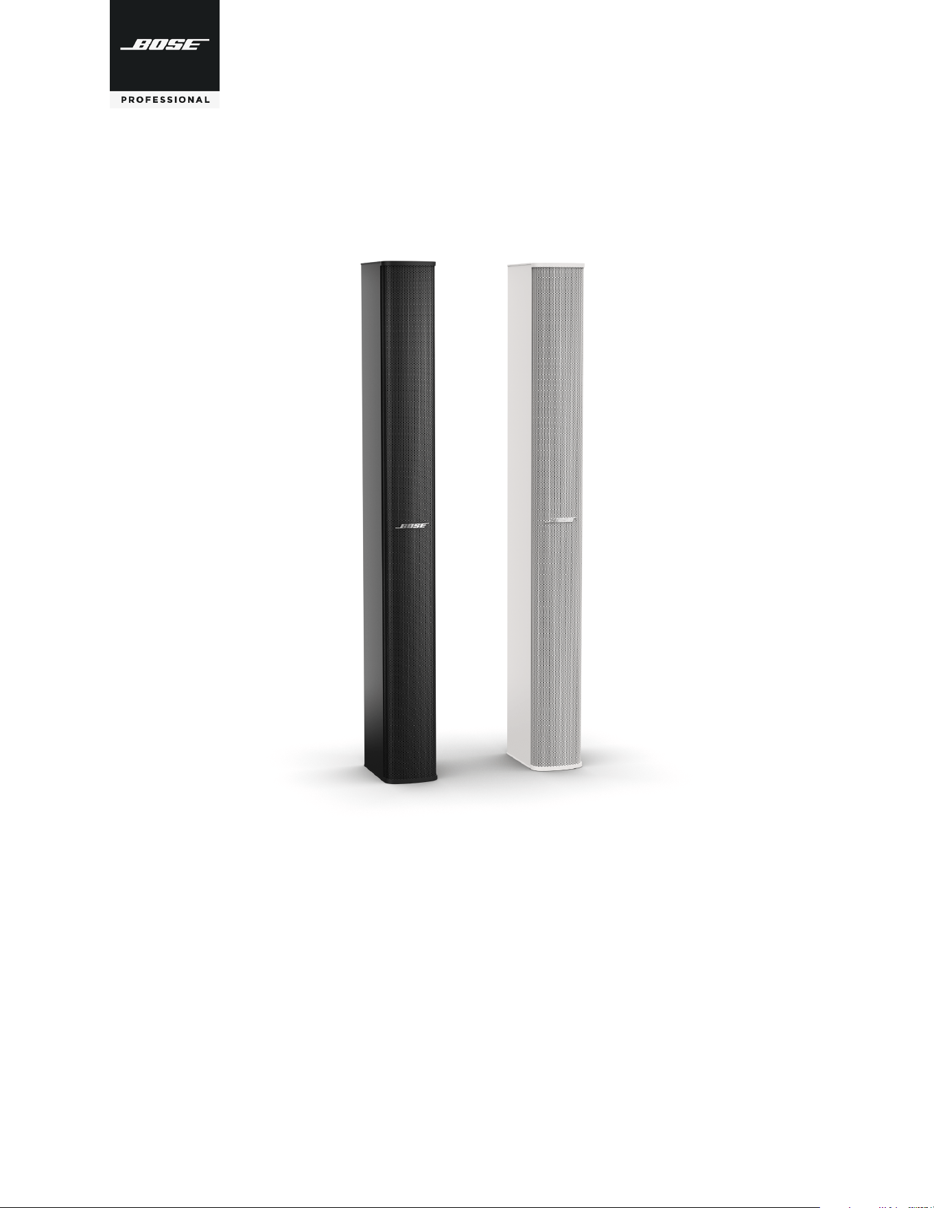
Max SPL, Throw Distance and Beam Control of Low-Frequency Content
The longer the array, the higher the maximum SPL and the longer the throw distance. Also, longer arrays can
vertically and digitally steer audio content down to a lower frequency, as indicated by Beam Control Limit.
The table below is a guide for these items:
Typical Usable
Throw Distance
1
Max SPL
2
Beam Control
LF Limit
Modules 10 m 20 m 30 m
1 10 m (33 ft) 97 dB 91 dB 88 dB 500 Hz
2 25 m (82 ft) 100 dB 96 dB 94 dB 250 Hz
3 35 m (115 ft) 101 dB 97 dB 95 dB 160 Hz
1
Typical Maximum Usable Throw Distance includes considerations for reverberation and speech intelligibility.
2
Max SPL calculated based on free-field (no boundary loading gain) sensitivity, exclusive of power compression, and without beam
steering, spreading or smoothing functions applied.
All calculations based on typical conditions with complex acoustic summation by Bose Modeler software; many competitor specifications
based on less accurate, distance-loss approximations.
For applications that exceed the general guidelines listed above, use Bose Modeler to predict SPL for a specific acoustic environment, or
contact your Bose Professional representative.
Conference rooms with lower ceilings and smaller steering angles may not have the same reverberation concerns and can mainly consider
Max SPL as a guiding factor for choosing between 1, 2 and 3 array modules.
Array Location (Height)
If you mount the array high on the wall and utilize a more significant steering angle closer to –20° and a wide
spreading angle to cover the front rows, a 2- or 3-module MSA12X configuration is highly recommended.
Dual Beam Mode
When using Dual Beam mode, it is recommended to use a 2- or 3-module MSA12X array for better pattern
control due to the longer array.
Reverberant Spaces
Generally, the primary use of columnar arrays is for speech reproduction. Also, most of these columnar arrays
tend to be highly used in reverberant spaces for the vertical pattern control.
The rule for these venues is, as reverberation time increases, stack more modules.
RT60* for Medium
to Large Venues
1 module 1.5 sec
2 module 3.0 sec
* These recommendations apply to “typical” medium sized venues with some rever-
beration concerns. In cases where your application exceeds the guidelines, design
tools such as Modeler software, should be used to determine system performance.
4 - Design Guide Design Guide - 5
Selecting Loudspeaker Models, Modules and Beam PatternsSelecting Loudspeaker Models, Modules and Beam Patterns
Is the MSA12X the Right Choice for the Application?
When considering the Panaray MSA12X modular steerable array loudspeaker vs. the passive Panaray MA12EX
modular line array loudspeaker, the MSA12X would be a good choice in the following scenarios:
Rooms that need a columnar loudspeaker installed vertically and tight-to-the wall for improved
aesthetics, allowing the loudspeaker to visually blend into the room. Panaray MSA12X arrays do not need
mechanical aiming, or pitch. They can also be mounted high on the wall, using digital steering to focus
sound down to audience areas.
Dicult rooms with high reverberation times that need the radiation pattern control oered by digital
beam steering. MSA12X arrays allow more precise targeting of audience areas, so you can decide where
you want to place (and not place) the acoustic energy. This level of control leads to better direct-to-
reverberant sound ratios and speech intelligibility in dicult rooms.
Rooms that require two audience zones to be covered by a single-column array.
Rooms that need a columnar loudspeaker recessed into surfaces.
Rooms with structural or design constraints that require the loudspeaker to be installed in non-ideal
locations.
Rooms that do not have an amplifier rack and can benefit from using a powered loudspeaker.
Rooms that already use, or are planning to use Dante® digital audio and control over Ethernet-based
networks.
Choosing Between 1, 2 or 3 Modules
When choosing the number of modules of an array, there are many elements to consider.
Max SPL, Throw Distance and Beam Control of Low-Frequency Content
The longer the array, the higher the maximum SPL and the longer the throw distance. Also, longer arrays can
vertically and digitally steer audio content down to a lower frequency, as indicated by Beam Control Limit.
The table below is a guide for these items:
Typical Usable
Throw Distance
1
Max SPL
2
Beam Control
LF Limit
Modules 10 m 20 m 30 m
1 10 m (33 ft) 97 dB 91 dB 88 dB 500 Hz
2 25 m (82 ft) 100 dB 96 dB 94 dB 250 Hz
3 35 m (115 ft) 101 dB 97 dB 95 dB 160 Hz
1
Typical Maximum Usable Throw Distance includes considerations for reverberation and speech intelligibility.
2
Max SPL calculated based on free-field (no boundary loading gain) sensitivity, exclusive of power compression, and without beam
steering, spreading or smoothing functions applied.
All calculations based on typical conditions with complex acoustic summation by Bose Modeler software; many competitor specifications
based on less accurate, distance-loss approximations.
For applications that exceed the general guidelines listed above, use Bose Modeler to predict SPL for a specific acoustic environment, or
contact your Bose Professional representative.
Conference rooms with lower ceilings and smaller steering angles may not have the same reverberation concerns and can mainly consider
Max SPL as a guiding factor for choosing between 1, 2 and 3 array modules.
Array Location (Height)
If you mount the array high on the wall and utilize a more significant steering angle closer to –20° and a wide
spreading angle to cover the front rows, a 2- or 3-module MSA12X configuration is highly recommended.
Dual Beam Mode
When using Dual Beam mode, it is recommended to use a 2- or 3-module MSA12X array for better pattern
control due to the longer array.
Reverberant Spaces
Generally, the primary use of columnar arrays is for speech reproduction. Also, most of these columnar arrays
tend to be highly used in reverberant spaces for the vertical pattern control.
The rule for these venues is, as reverberation time increases, stack more modules.
RT60* for Medium
to Large Venues
1 module 1.5 sec
2 module 3.0 sec
* These recommendations apply to “typical” medium sized venues with some rever-
beration concerns. In cases where your application exceeds the guidelines, design
tools such as Modeler software, should be used to determine system performance.
6 - Design Guide Design Guide - 7
Selecting Loudspeaker Models, Modules and Beam PatternsSelecting Loudspeaker Models, Modules and Beam Patterns
Choosing Beam Patterns
There are three beam pattern options for the Panaray MSA12X. You can choose the beam type depending on
the location of the array and shape of the coverage area.
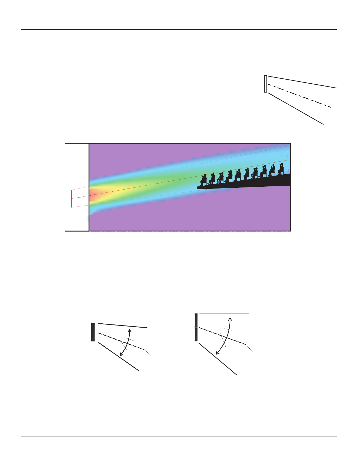
Basic Steer/Spread
Basic Steer/Spread is the most basic beam pattern. First, steer the axis of the
beam vertically, then spread the beam from that axis. Steering and Spreading
are independent from each other. If spreading is applied, the beam is spread
symmetrically from the steer axis. When the Steer angle = 0 and the Spread
angle=0, the radiation pattern of the array is the same as that of a (passive) non-
steerable columnar array, such as the Panaray MA12EX loudspeaker. Steer/Spread
works for the vertical plane only; horizontal steering/spreading is not supported.
Vocal Range Smoothing Option
Basic Steer/Spread has an option called Vocal Range Smoothing. With this option enabled (ON), the tonal
balance inside of the coverage becomes more consistent, and the sidelobes from the beam are suppressed.
The beam shape also becomes smoother, specifically around the vocal range. The trade-o of using this
option is that you lose a few dB of headroom.
Angular Limits
1-module array
Steer: ± 20°
Spread: Up to 30° (± 15°)
−20°
15°
15°
2- or 3-module array
Steer: ± 20°
Spread: Up to 40° (± 20°)
−20°
20°
20°
30°
40°
Ear
Height
0.3-0.8 m
(1’-2.5’)
Max Recommended
Vocal Range Smoothing Option
The Flat-Floor Optimized beam pattern also has an option called Vocal Range Smoothing. With this option
enabled, the tonal balance from front to back of the room becomes consistent around the vocal range, and
the sidelobes from the beam are suppressed. Again, the trade-o of this option is that you lose a few dB of
headroom. This feature is ON by default and recommended for this beam type.
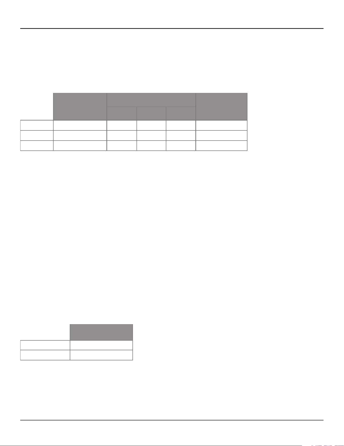
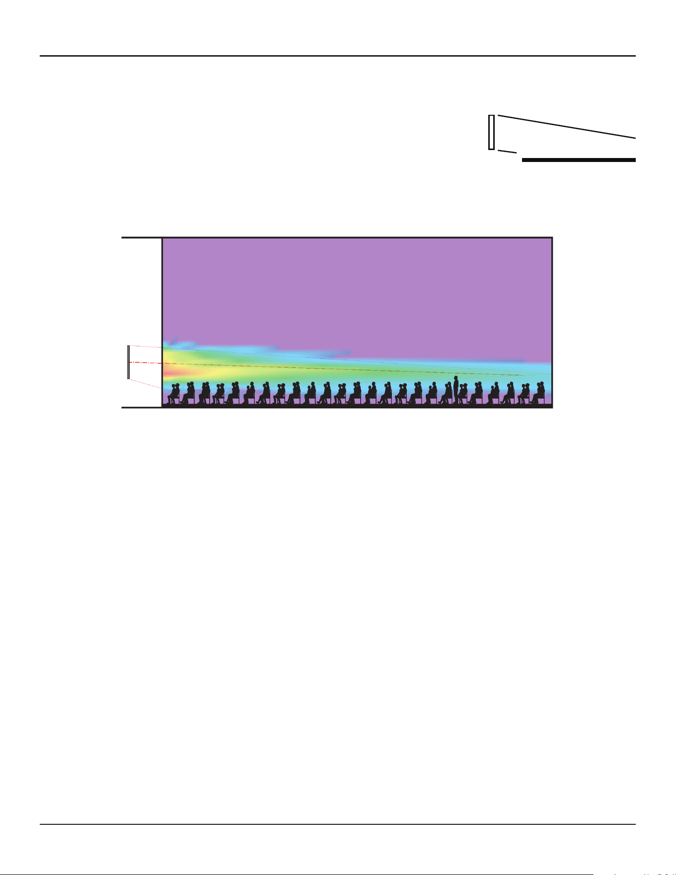
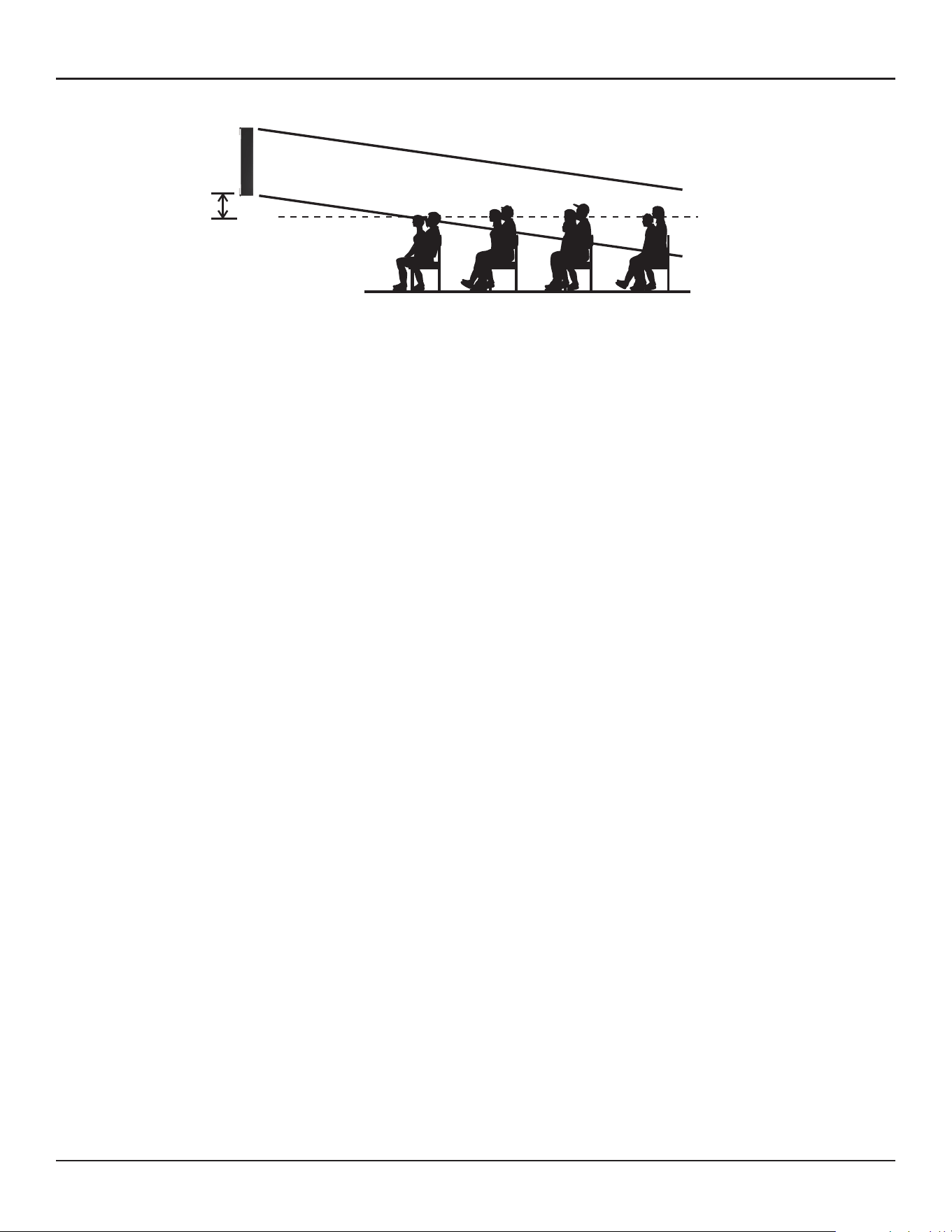
Flat-Floor Optimized
As the name suggests, Flat-Floor Optimized is a beam pattern that is optimized
for flat floors. With this beam type, you can only steer the beam. Spreading is
not available in this pattern. This beam type achieves consistent coverage from
the front row to the back row of the room, specifically around the vocal range.
Keep in mind that this beam pattern works best when the array is mounted at a
certain height: The bottom plate of the array should be mounted 0.3 to 0.8 m (1
to 2.5 feet) above the ear height of the audience. If the array is mounted higher
than this, or the floor is raked, choose a dierent beam type.
6 - Design Guide Design Guide - 7
Selecting Loudspeaker Models, Modules and Beam PatternsSelecting Loudspeaker Models, Modules and Beam Patterns
Choosing Beam Patterns
There are three beam pattern options for the Panaray MSA12X. You can choose the beam type depending on
the location of the array and shape of the coverage area.
Basic Steer/Spread
Basic Steer/Spread is the most basic beam pattern. First, steer the axis of the
beam vertically, then spread the beam from that axis. Steering and Spreading
are independent from each other. If spreading is applied, the beam is spread
symmetrically from the steer axis. When the Steer angle = 0 and the Spread
angle=0, the radiation pattern of the array is the same as that of a (passive) non-
steerable columnar array, such as the Panaray MA12EX loudspeaker. Steer/Spread
works for the vertical plane only; horizontal steering/spreading is not supported.
Vocal Range Smoothing Option
Basic Steer/Spread has an option called Vocal Range Smoothing. With this option enabled (ON), the tonal
balance inside of the coverage becomes more consistent, and the sidelobes from the beam are suppressed.
The beam shape also becomes smoother, specifically around the vocal range. The trade-o of using this
option is that you lose a few dB of headroom.
Angular Limits
1-module array
Steer: ± 20°
Spread: Up to 30° (± 15°)
−20°
15°
15°
2- or 3-module array
Steer: ± 20°
Spread: Up to 40° (± 20°)
−20°
20°
20°
30°
40°
Ear
Height
0.3-0.8 m
(1’-2.5’)
Max Recommended
Vocal Range Smoothing Option
The Flat-Floor Optimized beam pattern also has an option called Vocal Range Smoothing. With this option
enabled, the tonal balance from front to back of the room becomes consistent around the vocal range, and
the sidelobes from the beam are suppressed. Again, the trade-o of this option is that you lose a few dB of
headroom. This feature is ON by default and recommended for this beam type.
Flat-Floor Optimized
As the name suggests, Flat-Floor Optimized is a beam pattern that is optimized
for flat floors. With this beam type, you can only steer the beam. Spreading is
not available in this pattern. This beam type achieves consistent coverage from
the front row to the back row of the room, specifically around the vocal range.
Keep in mind that this beam pattern works best when the array is mounted at a
certain height: The bottom plate of the array should be mounted 0.3 to 0.8 m (1
to 2.5 feet) above the ear height of the audience. If the array is mounted higher
than this, or the floor is raked, choose a dierent beam type.
8 - Design Guide Design Guide - 9
Modeler Properties and OperationSelecting Loudspeaker Models, Modules and Beam Patterns
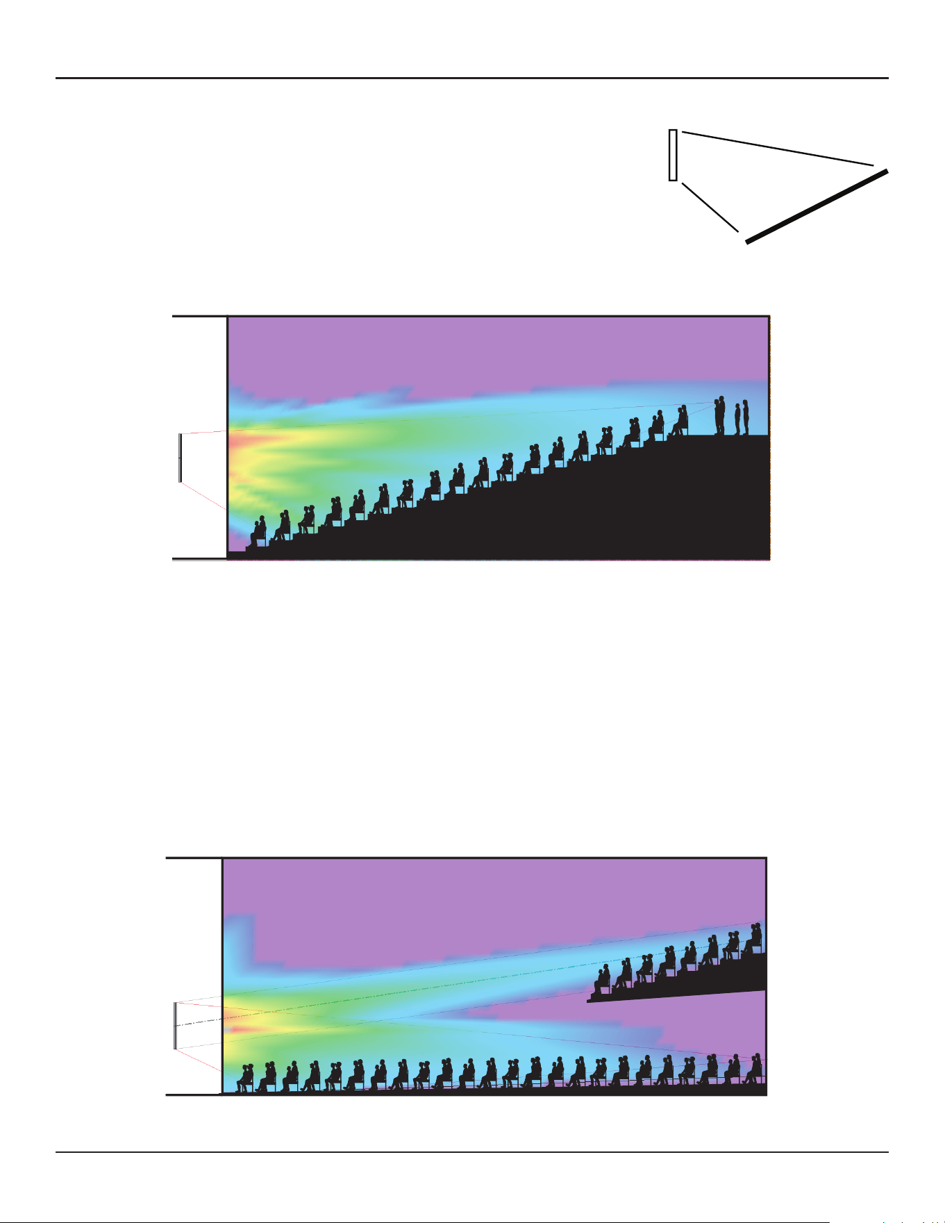
Raked-Floor Optimized
As the name suggests, Raked-Floor Optimized is a beam pattern that is
optimized for raked floors. The Raked-Floor Optimized beam type achieves a
vertically-asymmetrical beam radiation, which is suitable for covering a raked
floor, or covering a flat floor from a relatively high array position, such as when
the bottom plate of the array is more than 1 m (3.3 feet) above the ear height
of the audience.
This pattern does not oer the Vocal Range Smoothing option.
Dual Beam Mode
Up to two beams can be radiated from an MSA12X array built from 1, 2 or 3 modules, with any beam pattern
selected independently for each beam. You can also apply individual gain and Room EQ* for each beam.
Note: Dual Beam Mode is only available when using Dante® input.
Dual beams for the MSA12X is achieved by utilizing all the drivers of the array for both beams simultaneously.
By utilizing all the available drivers, better low-frequency directivity control for both beams can be achieved.
Other manufacturers may split their array into 2 smaller arrays (one on top of the other) to achieve dual
beams, but at the cost of performance.
* Supported Bose ControlSpace processor with Dante card required to apply individual room EQ for each beam
Dual Beam Mode, using Basic Steer/Spread and Raked-Floor Optimized
Selecting Beam Steering Software Tool
There are three options of methods to steer the vertical coverage of MSA12X. This will help you choose the
right software tool for your job.
1. Beam Steering in CSD
Choose this option when Basic/Steer is needed, and you do not need to see the coverage in the room.
Note: Vocal range smoothing is not available with this method.
2. Beam Steering in Bose Array Tool (Recommended)
Choose this option to quickly model an acoustic space and determine the loudspeaker array configuration
using all three beam pattern types and beam options.
Note: Windows OS version must be used to push array configuration to Control Space Designer to update
array.
3. Beam Steering in Modeler
Choose this option to create a detailed model of an acoustic space and determine the loudspeaker array
configuration using all three beam pattern types and options. Modeler is recommended for complex or
dicult spaces and includes computationally intensive predictions, including the full Speech Transmission
Index (STI).
Note: Both Bose Array Tool and Modeler allow system design without speaker present
How to use the Bose Array Tool (BAT) with MSA12X
1. Download the Bose Array Tool (BAT) for free from our website. bosepro.link/bat
2. Create your design in the BAT
3. When you are ready to update your array with the new beam pattern, click “Send to CSD”.
For additional details, including CSD actions, see “Send beam settingsfrom Bose Array Tool” or “Modeler”
section of this guide.
4. For additional help using the BAT, launch “Help” from within the BAT software.
8 - Design Guide Design Guide - 9
Modeler Properties and OperationSelecting Loudspeaker Models, Modules and Beam Patterns
Raked-Floor Optimized
As the name suggests, Raked-Floor Optimized is a beam pattern that is
optimized for raked floors. The Raked-Floor Optimized beam type achieves a
vertically-asymmetrical beam radiation, which is suitable for covering a raked
floor, or covering a flat floor from a relatively high array position, such as when
the bottom plate of the array is more than 1 m (3.3 feet) above the ear height
of the audience.
This pattern does not oer the Vocal Range Smoothing option.
Dual Beam Mode
Up to two beams can be radiated from an MSA12X array built from 1, 2 or 3 modules, with any beam pattern
selected independently for each beam. You can also apply individual gain and Room EQ* for each beam.
Note: Dual Beam Mode is only available when using Dante® input.
Dual beams for the MSA12X is achieved by utilizing all the drivers of the array for both beams simultaneously.
By utilizing all the available drivers, better low-frequency directivity control for both beams can be achieved.
Other manufacturers may split their array into 2 smaller arrays (one on top of the other) to achieve dual
beams, but at the cost of performance.
* Supported Bose ControlSpace processor with Dante card required to apply individual room EQ for each beam
Dual Beam Mode, using Basic Steer/Spread and Raked-Floor Optimized
Selecting Beam Steering Software Tool
There are three options of methods to steer the vertical coverage of MSA12X. This will help you choose the
right software tool for your job.
1. Beam Steering in CSD
Choose this option when Basic/Steer is needed, and you do not need to see the coverage in the room.
Note: Vocal range smoothing is not available with this method.
2. Beam Steering in Bose Array Tool (Recommended)
Choose this option to quickly model an acoustic space and determine the loudspeaker array configuration
using all three beam pattern types and beam options.
Note: Windows OS version must be used to push array configuration to Control Space Designer to update
array.
3. Beam Steering in Modeler
Choose this option to create a detailed model of an acoustic space and determine the loudspeaker array
configuration using all three beam pattern types and options. Modeler is recommended for complex or
dicult spaces and includes computationally intensive predictions, including the full Speech Transmission
Index (STI).
Note: Both Bose Array Tool and Modeler allow system design without speaker present
How to use the Bose Array Tool (BAT) with MSA12X
1. Download the Bose Array Tool (BAT) for free from our website. bosepro.link/bat
2. Create your design in the BAT
3. When you are ready to update your array with the new beam pattern, click “Send to CSD”.
For additional details, including CSD actions, see “Send beam settingsfrom Bose Array Tool” or “Modeler”
section of this guide.
4. For additional help using the BAT, launch “Help” from within the BAT software.
10 - Design Guide Design Guide - 11
Modeler Properties and OperationModeler Properties and Operation
Modeler Properties and Operation
In Modeler, you can look at the coverage both on the horizontal plane and the vertical plane in real time, and
adjust the beam shape to match the room. You can also specify parameters for the Basic Steer/Spread beam
type within ControlSpace Designer software (CSD) directly, without needing Modeler. Refer to the “Setting Up
MSA12X Basic Beam Steering and Spreading” topic in the CSD help system for more information.
Note: Room modeling using Modeler software is not covered in this document. For room modeling, refer to
Modeler help materials.
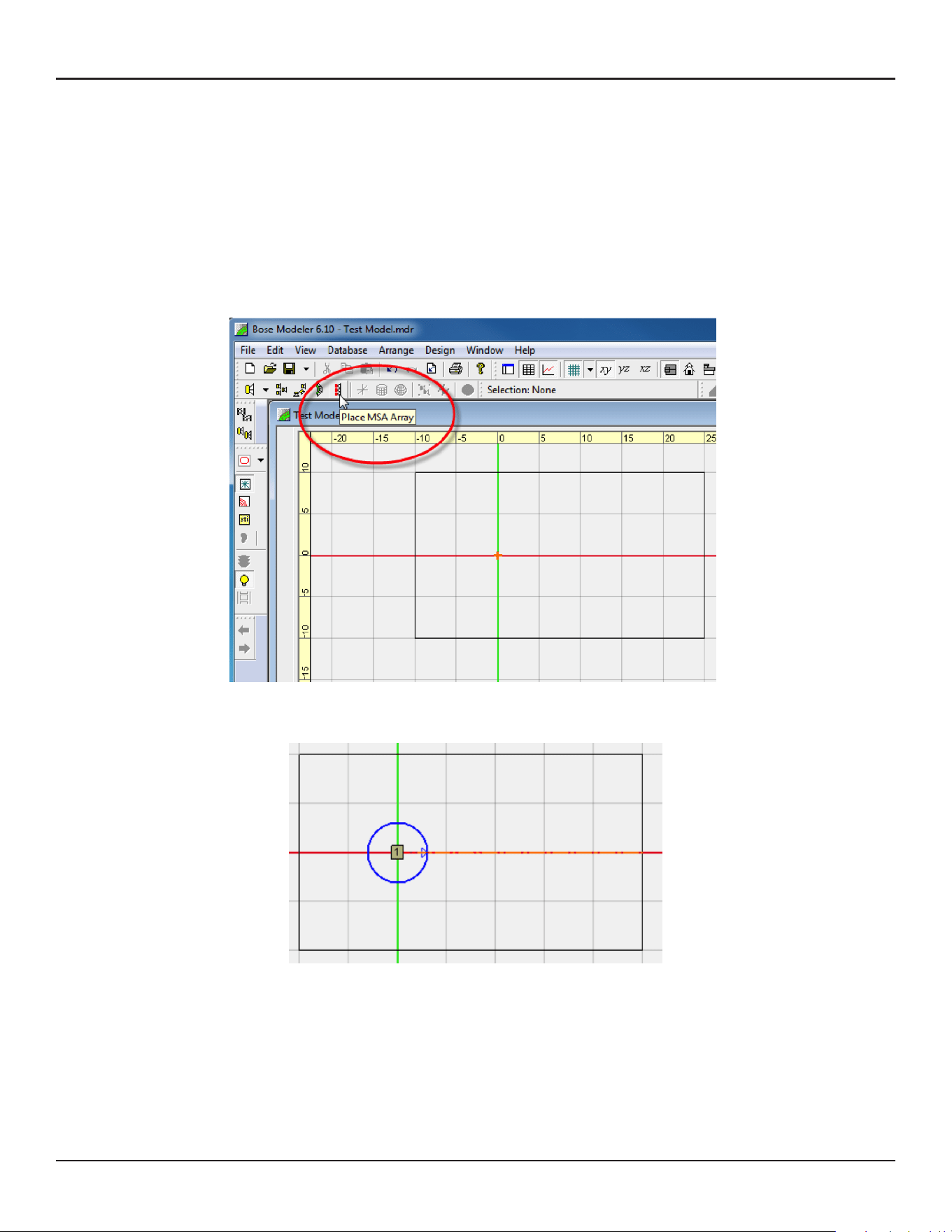
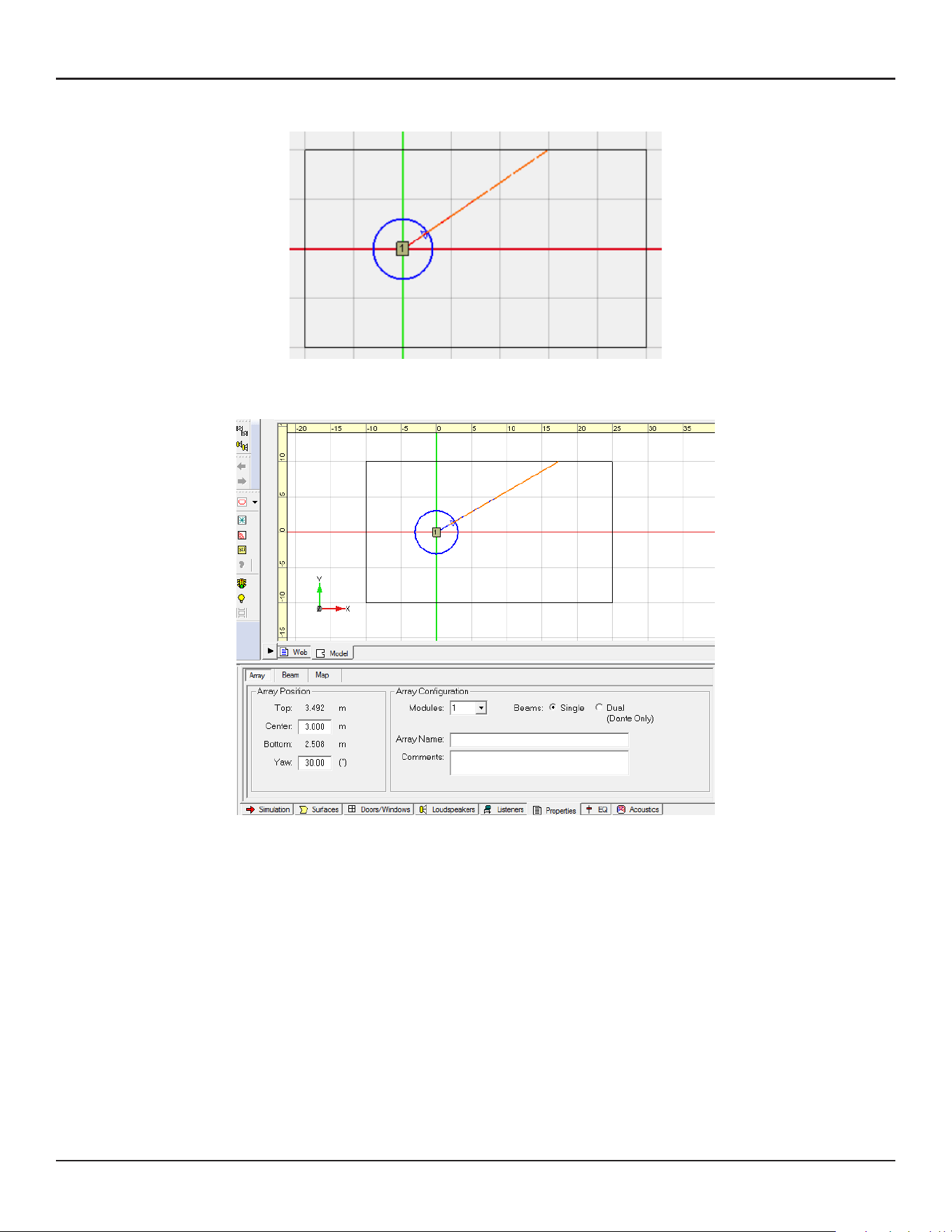
Place Array
Select ‘Place MSA Array’ Tool.
Click the surface in the Plan view and place an array.
Yaw the array if necessary. Select the blue arrow of the array aiming tool and move.
Click and select the array. Go to the Properties tab in the Detail View.
Change the array mounting position (height) in the Array Position frame. Center is the Z-coordinate of the
array center; Top is the MSA12X top plate; Bottom is MSA12X bottom plate.
10 - Design Guide Design Guide - 11
Modeler Properties and OperationModeler Properties and Operation
Modeler Properties and Operation
In Modeler, you can look at the coverage both on the horizontal plane and the vertical plane in real time, and
adjust the beam shape to match the room. You can also specify parameters for the Basic Steer/Spread beam
type within ControlSpace Designer software (CSD) directly, without needing Modeler. Refer to the “Setting Up
MSA12X Basic Beam Steering and Spreading” topic in the CSD help system for more information.
Note: Room modeling using Modeler software is not covered in this document. For room modeling, refer to
Modeler help materials.
Place Array
Select ‘Place MSA Array’ Tool.
Click the surface in the Plan view and place an array.
Yaw the array if necessary. Select the blue arrow of the array aiming tool and move.
Click and select the array. Go to the Properties tab in the Detail View.
Change the array mounting position (height) in the Array Position frame. Center is the Z-coordinate of the
array center; Top is the MSA12X top plate; Bottom is MSA12X bottom plate.
12 - Design Guide Design Guide - 13
Modeler Properties and OperationModeler Properties and Operation
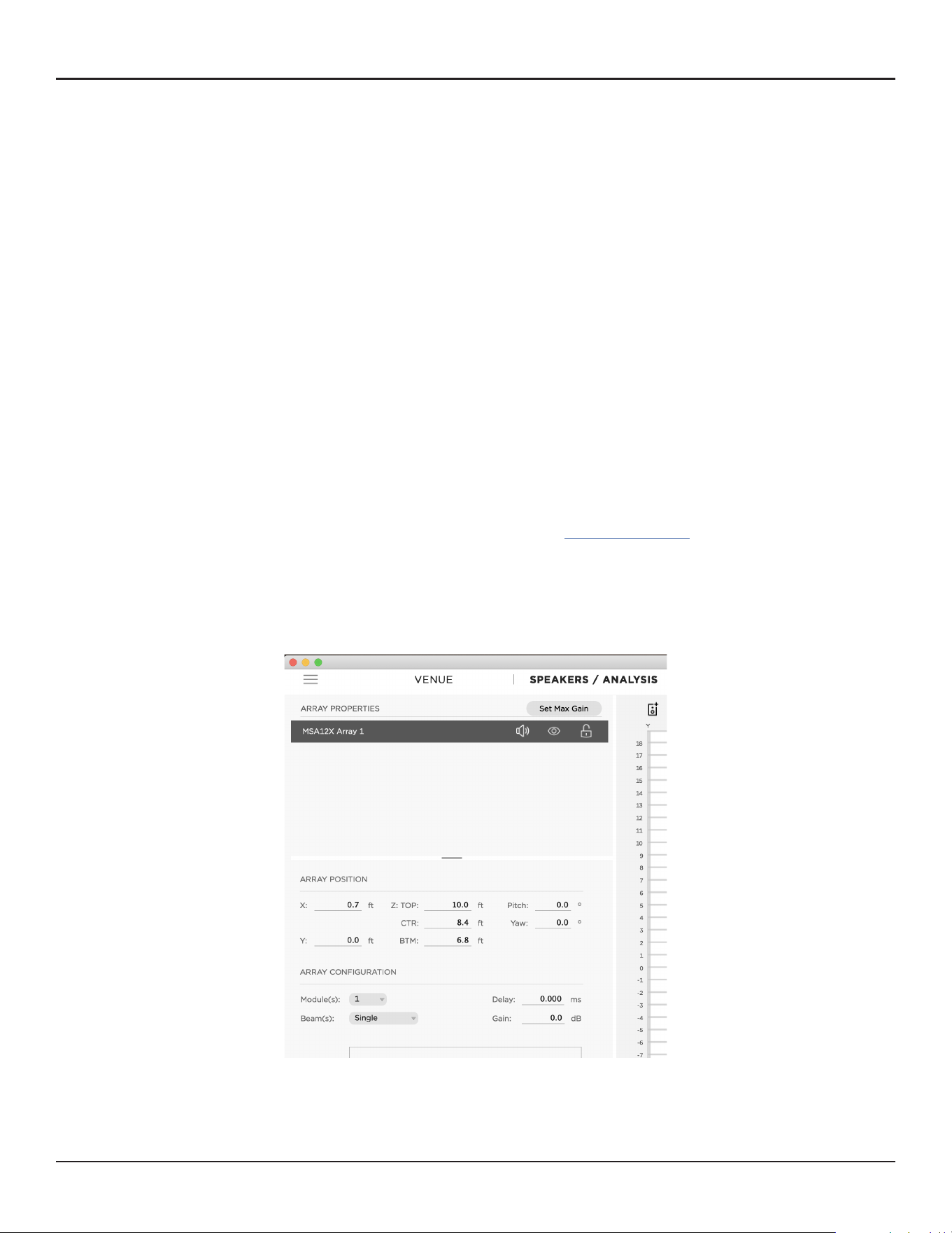
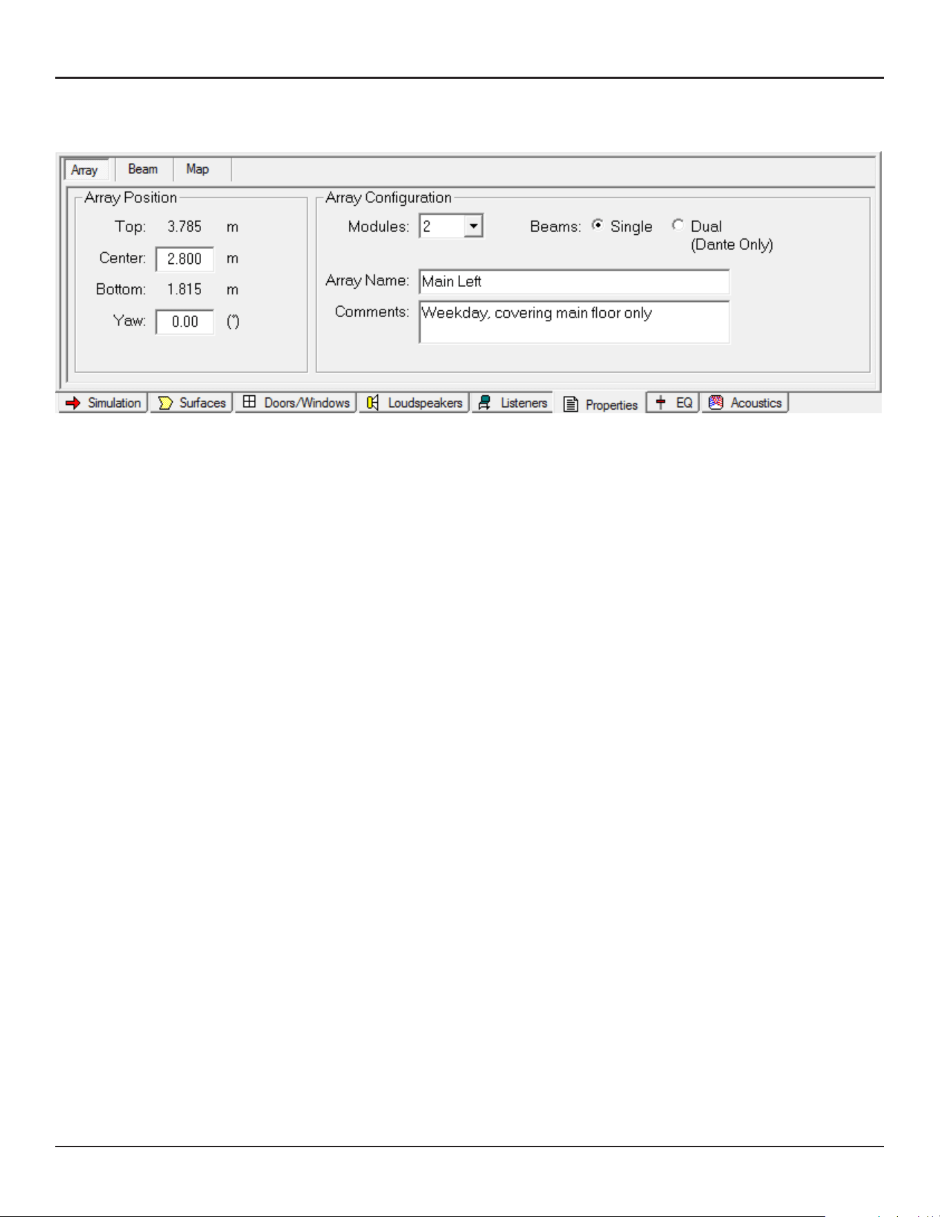
Array Tab
Basic properties of the array are set In the Array tab.
Array Position
Top/Center/Bottom: Set the Z-coordinate of the array. Center is for the array center; Top/Bottom are
for top/bottom plate of the array. Top/Bottom are linked to the Center. You can use the Top/Bottom
coordinate to specify the mounting height on site. Note that this is the Z-coordinate of the model, which
may not necessarily be the distance from floor (when the Z-coordinate of the floor is 0, they match).
Yaw: Set the yaw of the array.
Array Configuration
Modules: Specify the number of the modules in an array. Select from 1, 2 or 3.
Beams: Specify the number of the beams radiated from the array. Either Single beam or Dual beams.
Note: For the actual system, Dual beams are possible only using the Dante® input.
Array Name: You can name the array, such as ‘Main Left’. This name is used to manage the link between
Modeler and CSD later in the workflow.
Comments: This field can be used to describe the beam pattern (e.g. ‘Weekday, covering main floor only’,
‘Sunday, covering main floor + balcony’). The comments chosen in this field are indicated in CSD later in
the workflow. This can be useful when comparing multiple beam patterns for an array rather than looking
at parameter values (e.g. Steer -10°, Spread +10°).
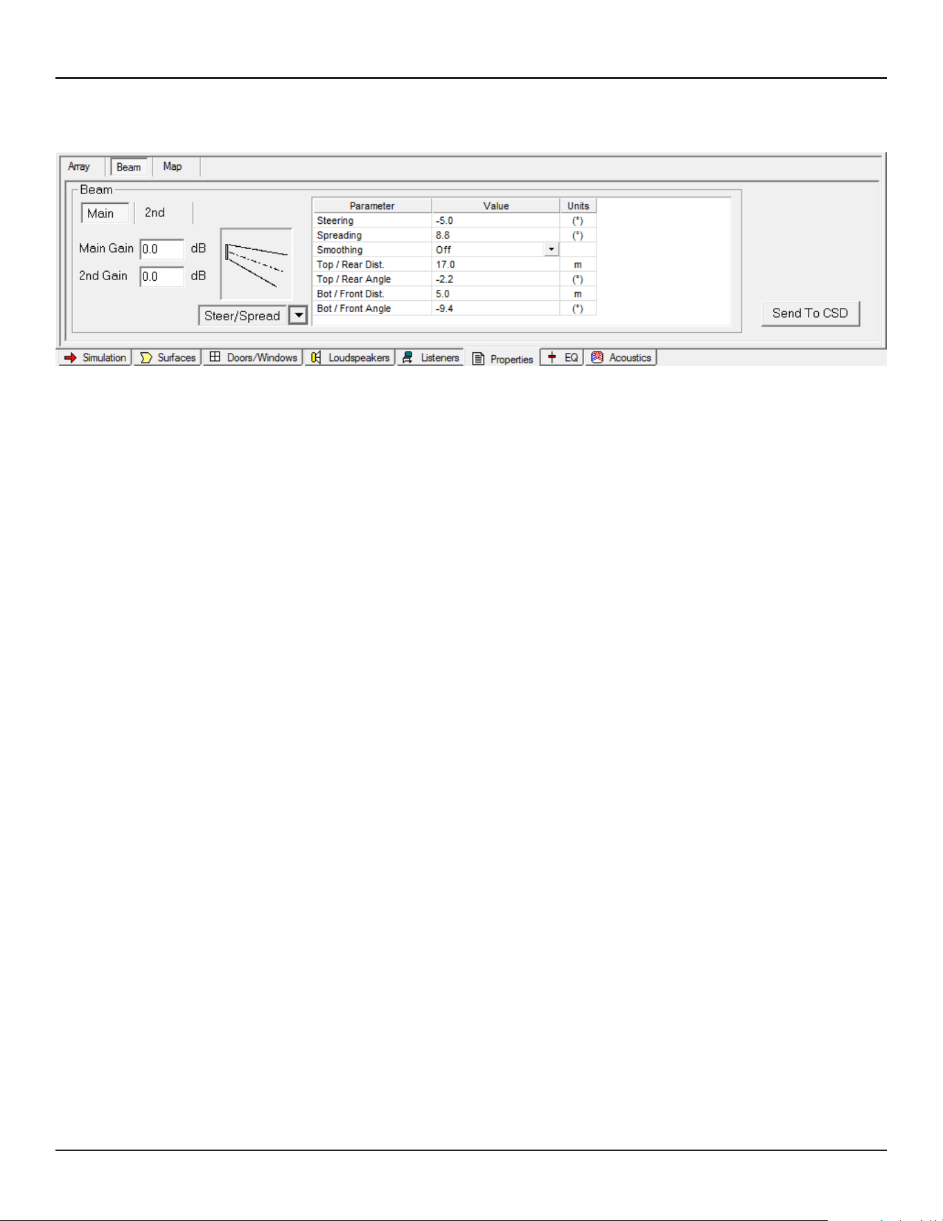
Beam Tab
In the Beam tab, you can specify the beam type and beam parameters.
Main/2nd: Selection for Main beam or Secondary beam. ‘2nd’ beam tab appears only when ‘Dual beam’ is
selected in the Array tab.
Main Gain/2nd Gain: Beam gain for main beam and second beam. ‘2nd Gain’ is grayed out when ‘Single
beam’ is selected in the Array tab.
Beam type selector: Select beam type from the drop-down box.
Beam parameters: Parameters to specify the beam shape.
Send to CSD: A button to export the computed beam coecients to CSD.
12 - Design Guide Design Guide - 13
Modeler Properties and OperationModeler Properties and Operation
Array Tab
Basic properties of the array are set In the Array tab.
Array Position
Top/Center/Bottom: Set the Z-coordinate of the array. Center is for the array center; Top/Bottom are
for top/bottom plate of the array. Top/Bottom are linked to the Center. You can use the Top/Bottom
coordinate to specify the mounting height on site. Note that this is the Z-coordinate of the model, which
may not necessarily be the distance from floor (when the Z-coordinate of the floor is 0, they match).
Yaw: Set the yaw of the array.
Array Configuration
Modules: Specify the number of the modules in an array. Select from 1, 2 or 3.
Beams: Specify the number of the beams radiated from the array. Either Single beam or Dual beams.
Note: For the actual system, Dual beams are possible only using the Dante® input.
Array Name: You can name the array, such as ‘Main Left’. This name is used to manage the link between
Modeler and CSD later in the workflow.
Comments: This field can be used to describe the beam pattern (e.g. ‘Weekday, covering main floor only’,
‘Sunday, covering main floor + balcony’). The comments chosen in this field are indicated in CSD later in
the workflow. This can be useful when comparing multiple beam patterns for an array rather than looking
at parameter values (e.g. Steer -10°, Spread +10°).
Beam Tab
In the Beam tab, you can specify the beam type and beam parameters.
Main/2nd: Selection for Main beam or Secondary beam. ‘2nd’ beam tab appears only when ‘Dual beam’ is
selected in the Array tab.
Main Gain/2nd Gain: Beam gain for main beam and second beam. ‘2nd Gain’ is grayed out when ‘Single
beam’ is selected in the Array tab.
Beam type selector: Select beam type from the drop-down box.
Beam parameters: Parameters to specify the beam shape.
Send to CSD: A button to export the computed beam coecients to CSD.
14 - Design Guide Design Guide - 15
User Interface for Beam ShapingUser Interface for Beam Shaping
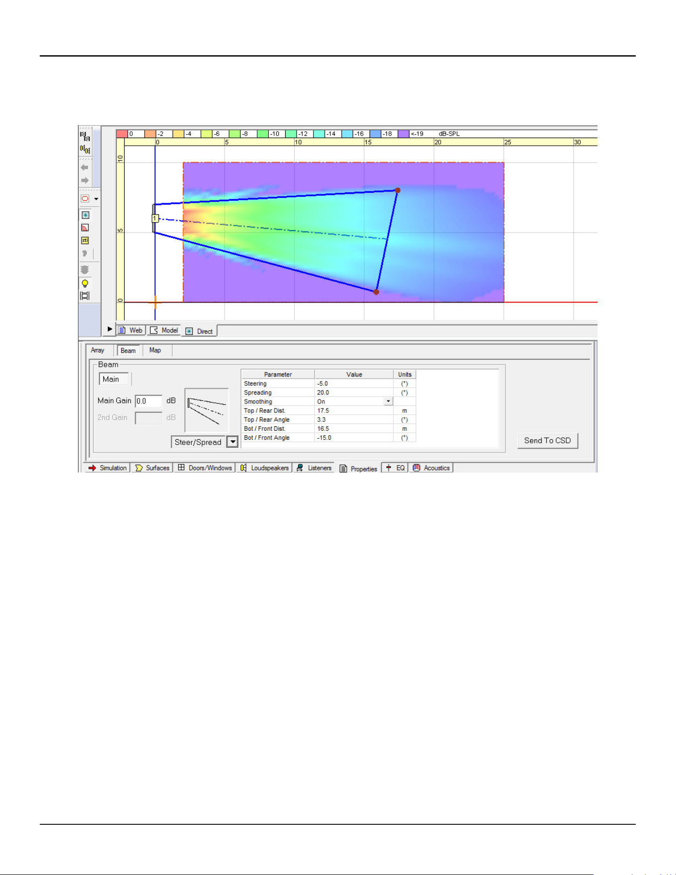
User Interface for Beam Shaping
Basic Steer/Spread
Select Steer/Spread from the beam type drop-down selector. With this beam type, the beam axis can be
steered vertically, and the beam can be spread symmetrically from that axis. You can adjust the beam shape
with one of the following:
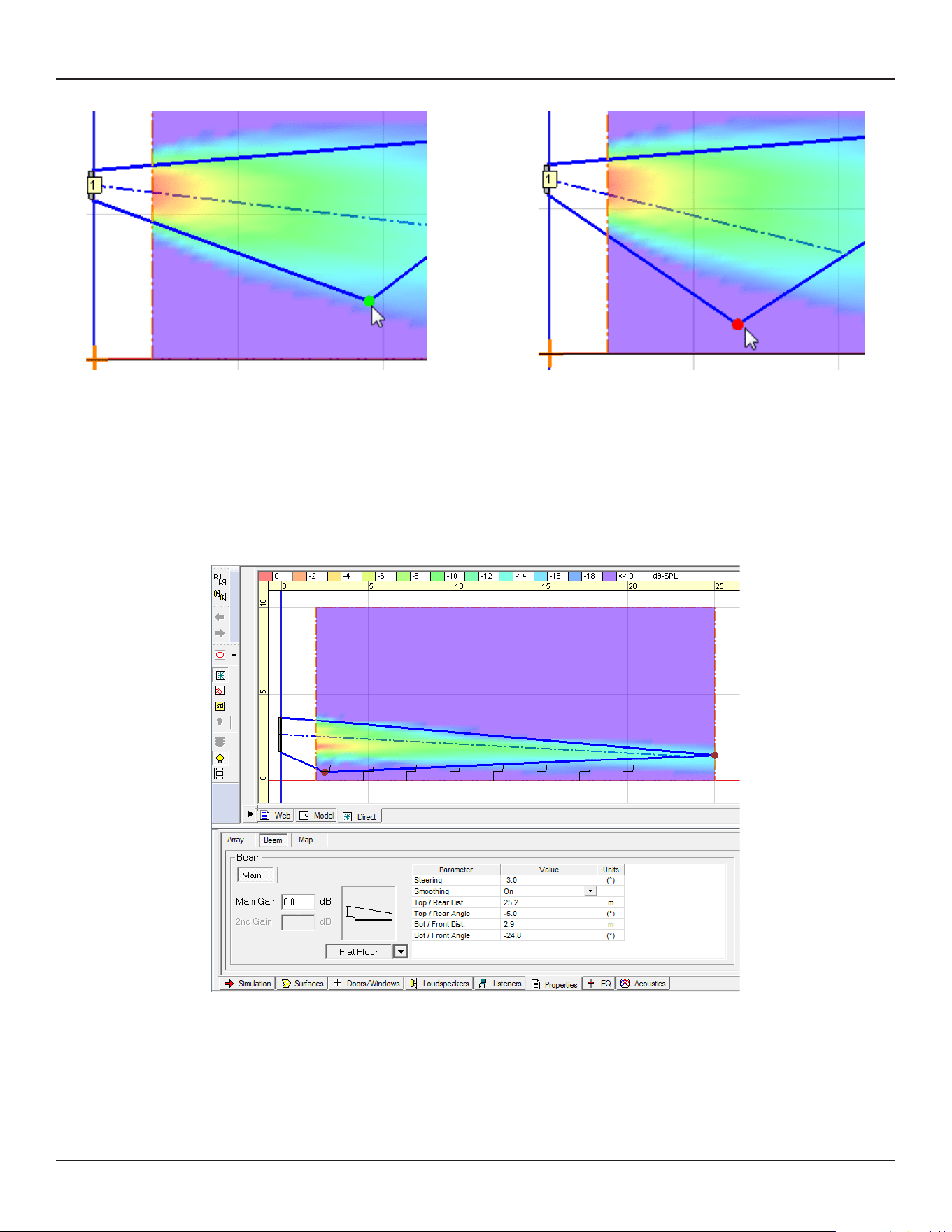
A: Enter Steering/Spreading angle values in the cell (Positive steering angle aims the beam upward).
B: Select and move the edges of Top (Rear) throw line and Bottom (Front) throw line on the Vertical
Coverage Map.
C: Enter the distance and angle values of the above throw lines in the cell.
A, B and C are linked and are automatically updated when the beam shape is changed.
When you move the edges on the Vertical map, select the Top (Rear) throw line edge and move to the target
point of far throw. Remember to take the ear height of the far-end listener into account. Repeat the same for
the Bottom (Front) throw.
Note: A sum of Top/Rear Angle and Bottom/Front Angle may not necessarily be the same as the Spreading
angle. This is because Modeler is adjusting the Steer/Spread angle to eectively cover the far throw target
point.
Each Beam type has its own limitation for the Beam Parameters. For example, you cannot spread the beam
too wide with Basic Steer/Spread. When you drag the edge, observe the color of the circle of the line edge; if
it is green, the edge is within the limitation. When it turns red, it is outside the limitation and the edge snaps
back to the original position.
Flat-Floor Optimized
Select Flat Floor from the beam type drop-down selector. This beam type is optimized for a flat-floor seating
arrangement. With this beam pattern, you can only steer the beam vertically, without any spreading. This
beam type can deliver consistent coverage from front to back specifically around the vocal range when the
array location (height) is appropriate, but if the array is located too high, you may not be able to achieve the
coverage you expect. Make sure the Bottom plate of the array is located 0.3 to 0.8 m (1 to 2.5 feet) above the
ear height of the audience.
Vocal Range Smoothing Option: Select either ON or OFF. With this option ON, the tonal balance inside the
coverage becomes more consistent and the sidelobes from the beam are suppressed and the beam shape
becomes smoother, specifically around voice range. The trade-o of this option is that you lose a few dB of
headroom. By default, Vocal Range Smoothing is OFF with Basic Steer/Spread.
Within the limitation (green) Outside of the limitation (red)
14 - Design Guide Design Guide - 15
User Interface for Beam ShapingUser Interface for Beam Shaping
User Interface for Beam Shaping
Basic Steer/Spread
Select Steer/Spread from the beam type drop-down selector. With this beam type, the beam axis can be
steered vertically, and the beam can be spread symmetrically from that axis. You can adjust the beam shape
with one of the following:
A: Enter Steering/Spreading angle values in the cell (Positive steering angle aims the beam upward).
B: Select and move the edges of Top (Rear) throw line and Bottom (Front) throw line on the Vertical
Coverage Map.
C: Enter the distance and angle values of the above throw lines in the cell.
A, B and C are linked and are automatically updated when the beam shape is changed.
When you move the edges on the Vertical map, select the Top (Rear) throw line edge and move to the target
point of far throw. Remember to take the ear height of the far-end listener into account. Repeat the same for
the Bottom (Front) throw.
Note: A sum of Top/Rear Angle and Bottom/Front Angle may not necessarily be the same as the Spreading
angle. This is because Modeler is adjusting the Steer/Spread angle to eectively cover the far throw target
point.
Each Beam type has its own limitation for the Beam Parameters. For example, you cannot spread the beam
too wide with Basic Steer/Spread. When you drag the edge, observe the color of the circle of the line edge; if
it is green, the edge is within the limitation. When it turns red, it is outside the limitation and the edge snaps
back to the original position.
Flat-Floor Optimized
Select Flat Floor from the beam type drop-down selector. This beam type is optimized for a flat-floor seating
arrangement. With this beam pattern, you can only steer the beam vertically, without any spreading. This
beam type can deliver consistent coverage from front to back specifically around the vocal range when the
array location (height) is appropriate, but if the array is located too high, you may not be able to achieve the
coverage you expect. Make sure the Bottom plate of the array is located 0.3 to 0.8 m (1 to 2.5 feet) above the
ear height of the audience.
Vocal Range Smoothing Option: Select either ON or OFF. With this option ON, the tonal balance inside the
coverage becomes more consistent and the sidelobes from the beam are suppressed and the beam shape
becomes smoother, specifically around voice range. The trade-o of this option is that you lose a few dB of
headroom. By default, Vocal Range Smoothing is OFF with Basic Steer/Spread.
Within the limitation (green) Outside of the limitation (red)
16 - Design Guide Design Guide - 17
User Interface for Beam ShapingUser Interface for Beam Shaping
1-module array
Steer: ± 20°
Spread: Up to 30° (± 15°)
−20°
15°
15°
2- or 3-module array
Steer: ± 20°
Spread: Up to 40° (± 20°)
−20°
20°
20°
30°
40°
Ear
Height
0.3-0.8 m
(1’-2.5’)
Max Recommended
The beam shape can be adjusted with one of the following:
A: Enter Steering angle value in the cell (Positive steering angle aims the beam upward).
B: Select and move the edges of Top (Rear) throw line and Bottom (Front) throw line on the Vertical
Coverage Map.
C: Enter the distance and angle values of the above throw lines in the cell.
A, B and C are linked and are automatically updated when the beam shape is changed.
When you move the edges on the Vertical map, select the Top (Rear) throw line edge and move to the target
point of far throw. Remember to take the ear height of the far-end listener into account. You can move the
Bottom (Front) throw line edge but it does not aect the beam shape.
Note: The Top/Rear Angle and Steering Angle may not necessarily be the same. This is because Modeler is
adjusting the Steer angle to eectively cover the far throw target point.
Each Beam type has its own limitation for the Beam Parameters. When you drag the edge, observe the color
of the circle of the line edge; if it is green, the edge is within the limitation. When it turns red, it is outside the
limitation and the edge snaps back to the original position.
Vocal Range Smoothing Option: Select either ON or OFF. With this option ON, the tonal balance inside the
coverage becomes more consistent, and the sidelobes from the beam are suppressed and the beam shape
becomes smoother, specifically around voice range. The trade-o of this option is that you lose a few dB of
headroom. By default, Vocal Range Smoothing is ON with Flat-Floor Optimized.
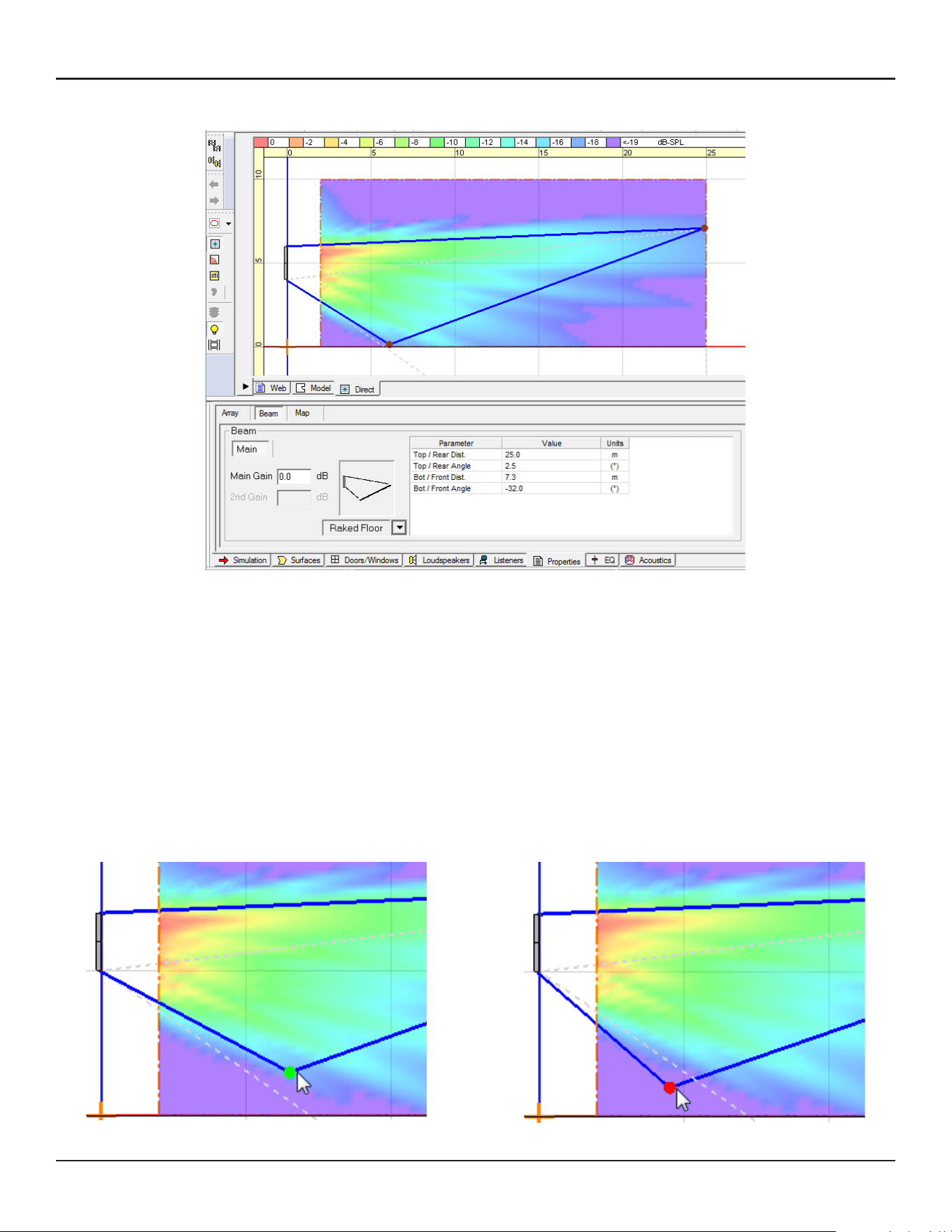
Raked-Floor Optimized
Select Raked Floor from the beam type selection. This beam type achieves a vertically asymmetrical beam
radiation, which is suitable for covering a raked floor, or covering a flat floor from a relatively high array
position.
The beam shape can be adjusted with one of the following:
A: Select and move the edges of Top (Rear) throw line and Bottom (Front) throw line on the Vertical
Coverage Map.
B: Enter the distance and angle values of the above throw lines in the cell.
A and B are linked and are automatically updated when the beam shape is changed.
Each Beam type has its own limitation for the Beam Parameters. For example, you cannot spread the beam
too much with Raked-Floor Optimized. When you drag the edge, observe the color of the circle of the line
edge; if it is green, the edge is within limitation. When it turns red, it is outside the limitation and the edge
snaps back to the original position.
Within the limitation (green) Outside of the limitation (red)
16 - Design Guide Design Guide - 17
User Interface for Beam ShapingUser Interface for Beam Shaping
1-module array
Steer: ± 20°
Spread: Up to 30° (± 15°)
−20°
15°
15°
2- or 3-module array
Steer: ± 20°
Spread: Up to 40° (± 20°)
−20°
20°
20°
30°
40°
Ear
Height
0.3-0.8 m
(1’-2.5’)
Max Recommended
The beam shape can be adjusted with one of the following:
A: Enter Steering angle value in the cell (Positive steering angle aims the beam upward).
B: Select and move the edges of Top (Rear) throw line and Bottom (Front) throw line on the Vertical
Coverage Map.
C: Enter the distance and angle values of the above throw lines in the cell.
A, B and C are linked and are automatically updated when the beam shape is changed.
When you move the edges on the Vertical map, select the Top (Rear) throw line edge and move to the target
point of far throw. Remember to take the ear height of the far-end listener into account. You can move the
Bottom (Front) throw line edge but it does not aect the beam shape.
Note: The Top/Rear Angle and Steering Angle may not necessarily be the same. This is because Modeler is
adjusting the Steer angle to eectively cover the far throw target point.
Each Beam type has its own limitation for the Beam Parameters. When you drag the edge, observe the color
of the circle of the line edge; if it is green, the edge is within the limitation. When it turns red, it is outside the
limitation and the edge snaps back to the original position.
Vocal Range Smoothing Option: Select either ON or OFF. With this option ON, the tonal balance inside the
coverage becomes more consistent, and the sidelobes from the beam are suppressed and the beam shape
becomes smoother, specifically around voice range. The trade-o of this option is that you lose a few dB of
headroom. By default, Vocal Range Smoothing is ON with Flat-Floor Optimized.
Raked-Floor Optimized
Select Raked Floor from the beam type selection. This beam type achieves a vertically asymmetrical beam
radiation, which is suitable for covering a raked floor, or covering a flat floor from a relatively high array
position.
The beam shape can be adjusted with one of the following:
A: Select and move the edges of Top (Rear) throw line and Bottom (Front) throw line on the Vertical
Coverage Map.
B: Enter the distance and angle values of the above throw lines in the cell.
A and B are linked and are automatically updated when the beam shape is changed.
Each Beam type has its own limitation for the Beam Parameters. For example, you cannot spread the beam
too much with Raked-Floor Optimized. When you drag the edge, observe the color of the circle of the line
edge; if it is green, the edge is within limitation. When it turns red, it is outside the limitation and the edge
snaps back to the original position.
Within the limitation (green) Outside of the limitation (red)
18 - Design Guide Design Guide - 19
User Interface for Beam ShapingUser Interface for Beam Shaping
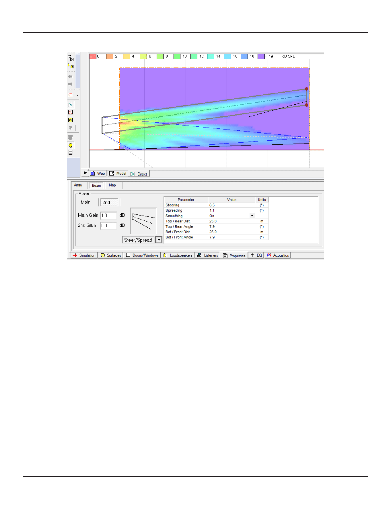
Dual Beam Mode
Dual Beam mode radiates two beams from a MSA12X array. When you have selected Dual in the Array tab
(see page 11), a 2nd tab appears for the secondary beam. You can choose any of the three beam types for
each beam (Main beam and Secondary beam) independently. You can also apply beam gains for each beam
to balance the level at the seating area.
By selecting the ‘Main’ and ‘2nd’ tab, the beam type selection and corresponding parameters displayed are
switched.
Note: Dual beam is only possible by using the Dante® input with the actual system (Modeler does not have
property to set the input type). When saving Modeler steering in CSD with Dual Beams, ensure Dante input is
selected before saving.
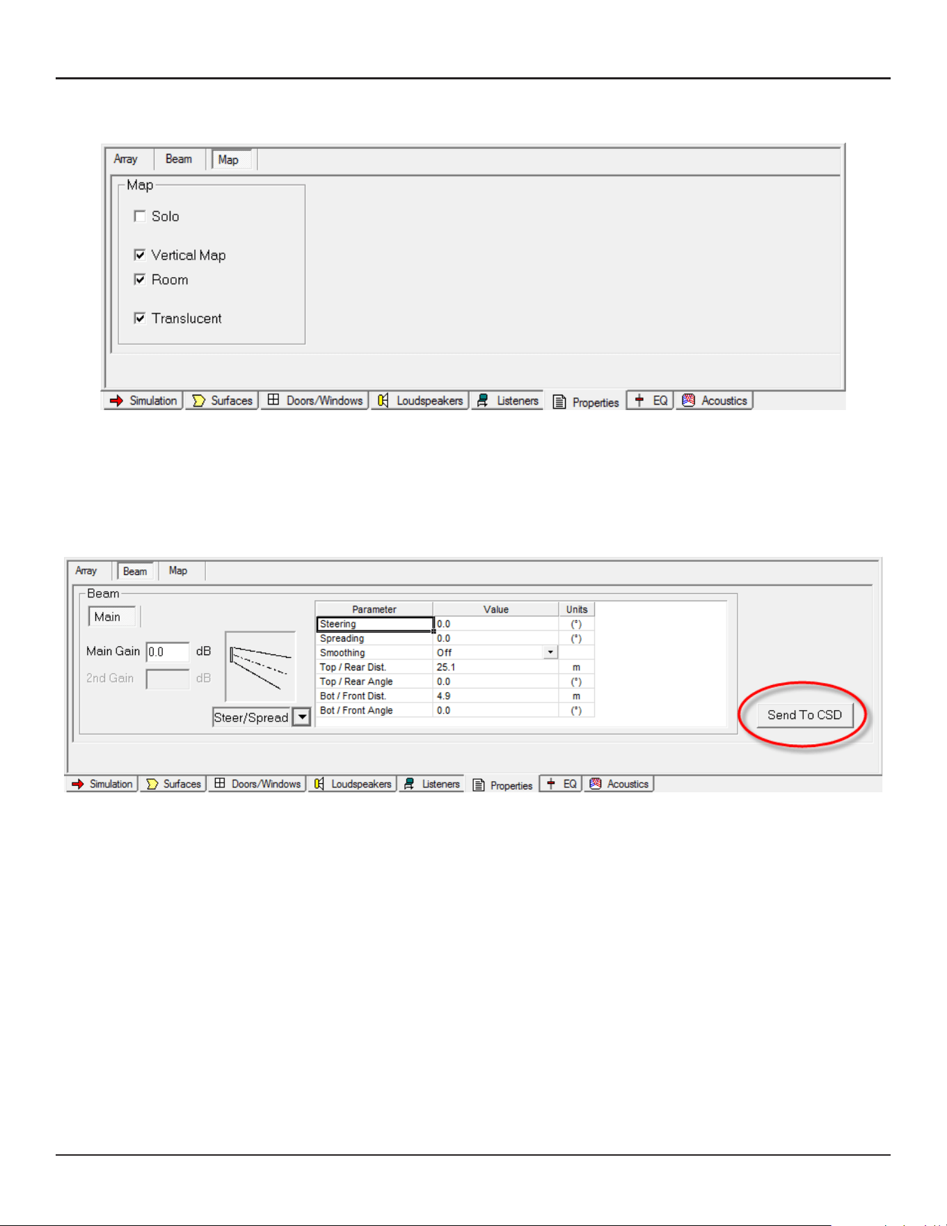
Map Tab
The Map tab is used for changing the properties for SPL mapping.
Solo: Mutes/Unmutes the array and loudspeakers in the model.
Vertical Map: Activate/Deactivate the Vertical Map.
Room: Activate/Deactivate the SPL map for the room surfaces specified in the Simulation tab.
Translucent: Activate/Deactivate the Translucent option for the SPL map.
Send to CSD
When you finish the beam shape design in Modeler, and save the file, the next step is to transfer the data that
Modeler computes based on your setting into ControlSpace Designer software (CSD).
Launch CSD. Return to Modeler and select the Beam tab again. Then, click the ‘Send to CSD’ button on the
far right.
Note: CSD must be open and running on the same machine as Modeler for the data transfer to work. Ensure
you have CSD 5.0 or later.
18 - Design Guide Design Guide - 19
User Interface for Beam ShapingUser Interface for Beam Shaping
Dual Beam Mode
Dual Beam mode radiates two beams from a MSA12X array. When you have selected Dual in the Array tab
(see page 11), a 2nd tab appears for the secondary beam. You can choose any of the three beam types for
each beam (Main beam and Secondary beam) independently. You can also apply beam gains for each beam
to balance the level at the seating area.
By selecting the ‘Main’ and ‘2nd’ tab, the beam type selection and corresponding parameters displayed are
switched.
Note: Dual beam is only possible by using the Dante® input with the actual system (Modeler does not have
property to set the input type). When saving Modeler steering in CSD with Dual Beams, ensure Dante input is
selected before saving.
Map Tab
The Map tab is used for changing the properties for SPL mapping.
Solo: Mutes/Unmutes the array and loudspeakers in the model.
Vertical Map: Activate/Deactivate the Vertical Map.
Room: Activate/Deactivate the SPL map for the room surfaces specified in the Simulation tab.
Translucent: Activate/Deactivate the Translucent option for the SPL map.
Send to CSD
When you finish the beam shape design in Modeler, and save the file, the next step is to transfer the data that
Modeler computes based on your setting into ControlSpace Designer software (CSD).
Launch CSD. Return to Modeler and select the Beam tab again. Then, click the ‘Send to CSD’ button on the
far right.
Note: CSD must be open and running on the same machine as Modeler for the data transfer to work. Ensure
you have CSD 5.0 or later.

20 - Design Guide Design Guide - 21
Array SetupUser Interface for Beam Shaping
Manage Multiple Beam Patterns
If you have a select Bose ControlSpace processor in your system (see table below), you can set multiple beam
patterns in an array and set up end user recall of these settings.
Below is the process to keep each beam pattern in a Modeler .mdr file:
1. Name the Array Name (e.g. ‘Main Left’) in the Array tab.
2. Design the beam shape (pattern A) and add short description of the beam in the ‘Comments’ field (e.g.
“Weekday, covering main floor only”).
3. Save the .mdr file with an appropriate name (e.g. ‘Weekday.mdr’).
4. Duplicate the .mdr file and rename (e.g. ‘Sunday.mdr’).
5. Design the beam shape (pattern B) for the same array and change the short description in the ‘Comments’
field (e.g. “Sunday, covering main floor and balcony).
Note: At this point, the Array Name and number of modules of the array should be the same as before.
6. Save the .mdr file.
Later in the workflow, we link the array in Modeler and the actual array through ControlSpace Designer
software, and as long as the array name and number of modules are the same, we can maintain that link for
dierent beam patterns stored in multiple .mdr files.
Supported ControlSpace Processor Models
EX-1280C
ESP-880A
ESP-880AD
ESP-1240A
ESP-1240AD
ESP-880A (discontinued)
ESP-1240 (discontinued)
ESP-4120 (discontinued)
ESP-1600 (discontinued)
Array Setup
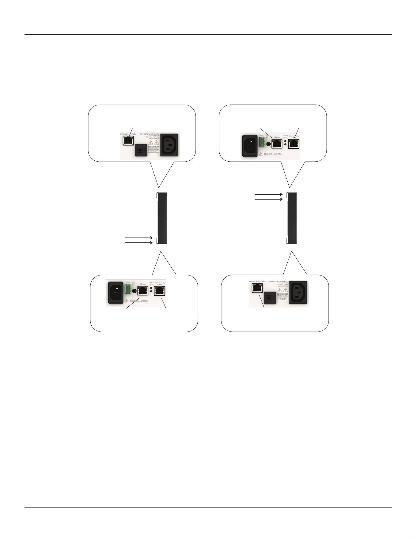
Wiring
When you mount a MSA12X, you can choose the orientation: Control from Bottom or Control from Top. Once
you mount the array, you have to specify the orientation in ControlSpace Designer software (CSD), otherwise
the beam could point toward the ceiling!
RJ-45
(Ethernet)
RJ-50
(Expansion)
RJ-50
(Expansion)
Control
(Ethernet)
Power
RJ-45
(Ethernet)
RJ-50
(Expansion)
RJ-50
(Expansion)
Control
(Ethernet)
Power
Contr
ol from Bottom Control from Top
(Default Orientation)
20 - Design Guide Design Guide - 21
Array SetupUser Interface for Beam Shaping
Manage Multiple Beam Patterns
If you have a select Bose ControlSpace processor in your system (see table below), you can set multiple beam
patterns in an array and set up end user recall of these settings.
Below is the process to keep each beam pattern in a Modeler .mdr file:
1. Name the Array Name (e.g. ‘Main Left’) in the Array tab.
2. Design the beam shape (pattern A) and add short description of the beam in the ‘Comments’ field (e.g.
“Weekday, covering main floor only”).
3. Save the .mdr file with an appropriate name (e.g. ‘Weekday.mdr’).
4. Duplicate the .mdr file and rename (e.g. ‘Sunday.mdr’).
5. Design the beam shape (pattern B) for the same array and change the short description in the ‘Comments’
field (e.g. “Sunday, covering main floor and balcony).
Note: At this point, the Array Name and number of modules of the array should be the same as before.
6. Save the .mdr file.
Later in the workflow, we link the array in Modeler and the actual array through ControlSpace Designer
software, and as long as the array name and number of modules are the same, we can maintain that link for
dierent beam patterns stored in multiple .mdr files.
Supported ControlSpace Processor Models
EX-1280C
ESP-880A
ESP-880AD
ESP-1240A
ESP-1240AD
ESP-880A (discontinued)
ESP-1240 (discontinued)
ESP-4120 (discontinued)
ESP-1600 (discontinued)
Array Setup
Wiring
When you mount a MSA12X, you can choose the orientation: Control from Bottom or Control from Top. Once
you mount the array, you have to specify the orientation in ControlSpace Designer software (CSD), otherwise
the beam could point toward the ceiling!
RJ-45
(Ethernet)
RJ-50
(Expansion)
RJ-50
(Expansion)
Control
(Ethernet)
Power
RJ-45
(Ethernet)
RJ-50
(Expansion)
RJ-50
(Expansion)
Control
(Ethernet)
Power
Contr
ol from Bottom Control from Top
(Default Orientation)
22 - Design Guide Design Guide - 23
CSD Properties and OperationArray Setup
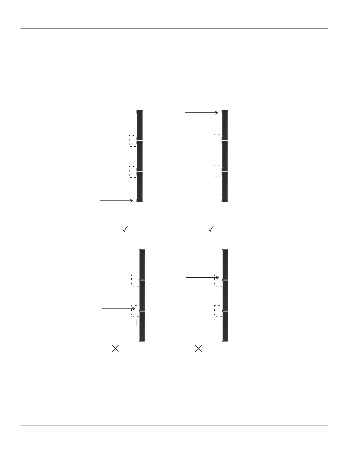
You can configure a longer array by stacking multiple modules and connect the modules by an expansion
cable. Up to a 3-module array is supported. The end connectors of an expansion cable are RJ-50 (cable
supplied), which is dierent from the RJ-45 for Control/Dante® (Ethernet), although they look similar. Take
notice when setting up a multi-module array.
For a multi-module array, the Ethernet cable has to be inserted to the receptacle located at the end of
the array, and the module in which the Ethernet cable is inserted becomes the Master module of the array
automatically. Audio signal and control signal are passed to the slave module(s) via the RJ-50 expansion
cable between the modules. You cannot insert the Ethernet cable into the modules other than the one
mentioned above. The array does not work when you insert the Ethernet cable into the wrong modules.
The master module represents the entire array; the IP address of the master module applies to the entire
array. i.e. a multi-module array can be seen as a single device; it is just a long array with more drivers than a
single-module array.
Mounting
Refer to the MSA12X Installation Guide available on PRO.BOSE.COM.
Control from Top
Master
Module
Ethernet
RJ-45
Expansion
Master
Module
Control from Bottom
Ethernet
RJ-45
Expansion
Expansion
Expansion
No Good
Ethernet
RJ-45
Expansion
Expansion
No Good
RJ-45
Expansion
Expansion
Good
Ethernet
Good
CSD Properties and Operation
ControlSpace Designer software (CSD) is used to transfer the beam pattern and mode (single or dual beam)
configuration to MSA12X loudspeakers.
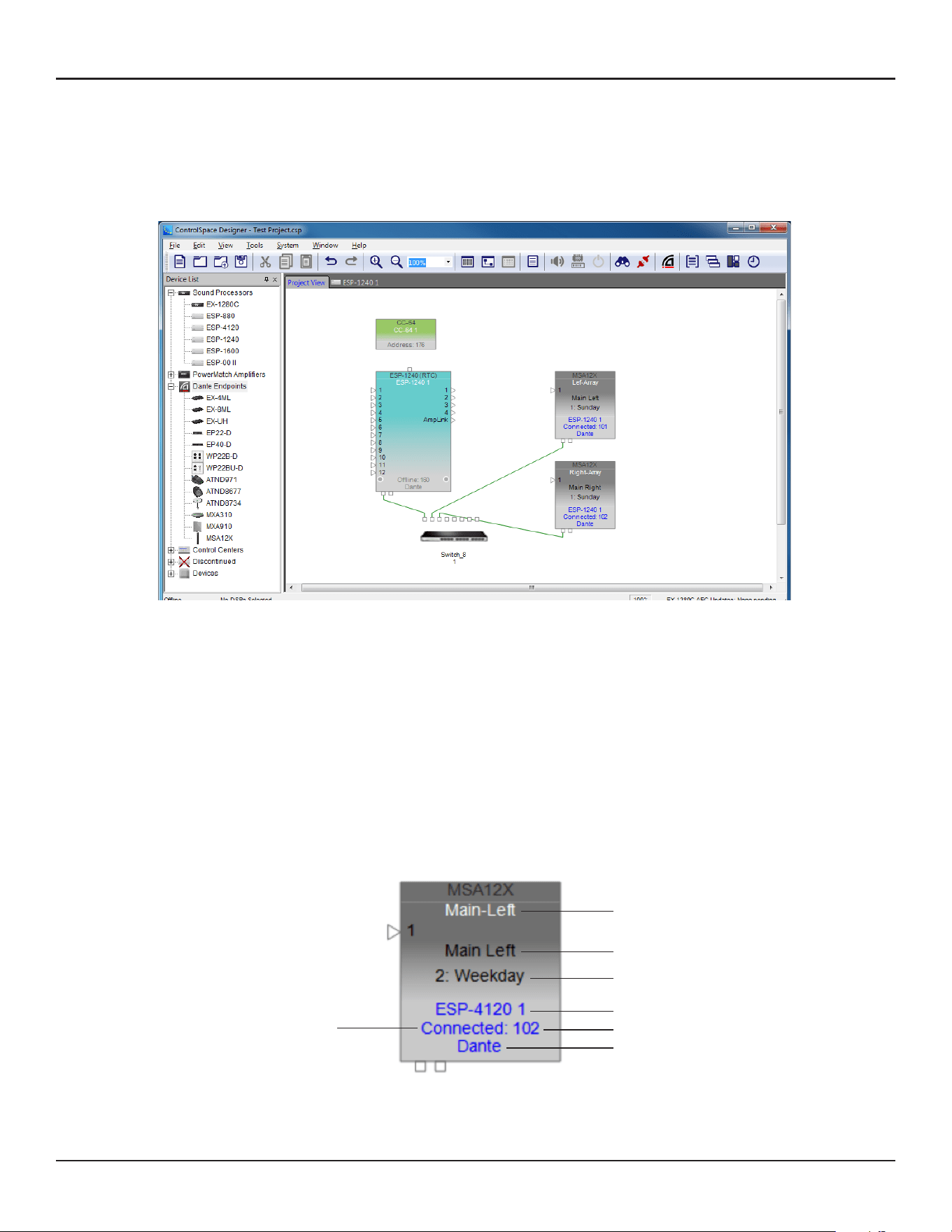
MSA12X Device Block in Project View
When you add a MSA12X to a CSD Project, the device block appears in the Project view. There are a few ways
to add a MSA12X to a CSD Project.
On the device block, the following can be seen:
1. Device Name
2. Array Name in design (blank if not set)
3. Current Beam Preset
4. Device name of signal processor that the array is associated with (blank if not associated)
5. Connection status between CSD and the device
6. Last octet of IP address
7. Input type (Dante® or Analog)
You can rename the Device Name by right-clicking (or press F2 key).
q
w
e
r
y
u
t
22 - Design Guide Design Guide - 23
CSD Properties and OperationArray Setup
You can configure a longer array by stacking multiple modules and connect the modules by an expansion
cable. Up to a 3-module array is supported. The end connectors of an expansion cable are RJ-50 (cable
supplied), which is dierent from the RJ-45 for Control/Dante® (Ethernet), although they look similar. Take
notice when setting up a multi-module array.
For a multi-module array, the Ethernet cable has to be inserted to the receptacle located at the end of
the array, and the module in which the Ethernet cable is inserted becomes the Master module of the array
automatically. Audio signal and control signal are passed to the slave module(s) via the RJ-50 expansion
cable between the modules. You cannot insert the Ethernet cable into the modules other than the one
mentioned above. The array does not work when you insert the Ethernet cable into the wrong modules.
The master module represents the entire array; the IP address of the master module applies to the entire
array. i.e. a multi-module array can be seen as a single device; it is just a long array with more drivers than a
single-module array.
Mounting
Refer to the MSA12X Installation Guide available on PRO.BOSE.COM.
Control from Top
Master
Module
Ethernet
RJ-45
Expansion
Master
Module
Control from Bottom
Ethernet
RJ-45
Expansion
Expansion
Expansion
No Good
Ethernet
RJ-45
Expansion
Expansion
No Good
RJ-45
Expansion
Expansion
Good
Ethernet
Good
CSD Properties and Operation
ControlSpace Designer software (CSD) is used to transfer the beam pattern and mode (single or dual beam)
configuration to MSA12X loudspeakers.
MSA12X Device Block in Project View
When you add a MSA12X to a CSD Project, the device block appears in the Project view. There are a few ways
to add a MSA12X to a CSD Project.
On the device block, the following can be seen:
1. Device Name
2. Array Name in design (blank if not set)
3. Current Beam Preset
4. Device name of signal processor that the array is associated with (blank if not associated)
5. Connection status between CSD and the device
6. Last octet of IP address
7. Input type (Dante® or Analog)
You can rename the Device Name by right-clicking (or press F2 key).
q
w
e
r
y
u
t
24 - Design Guide Design Guide - 25
CSD Properties and OperationCSD Properties and Operation
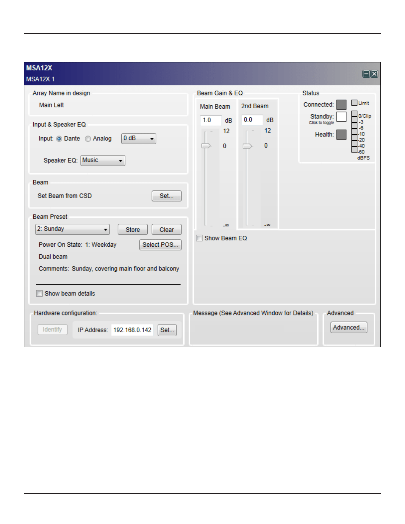
MSA12X Control Panel
By double-clicking the device block in the Project View, the MSA12X control panel appears.
Array Name in Design
The name of the array specified in Modeler. By default, this is blank.
Input & Speaker EQ
Input: Select from Dante® or Analog, followed by the input gain. The input gain is independent between
Dante and Analog.
Speaker EQ: Select from Music or Voice.
Beam
Set Beam from CSD: You can set the beam steering and spreading without needing Modeler.
Note: This is limited to the Basic Steer/Spread.
Beam Preset
You can store/recall the beam pattern and Power On State here.
Basic beam description: Shows beam mode and comments details as entered in Modeler.
Show beam details: Indicates the detailed beam parameters specified in Modeler.
Beam Gain & EQ
Beam Gain: Gain for each beam.
Show Beam EQ: Indicates the Beam EQ. A Beam EQ is a filter that compensates the tonal balance of each
beam corresponding to the beam shape. The filter curve is automatically computed and updated every
time the beam pattern is sent from Modeler. You can change the curve shape manually and store to a
Beam Preset.
Freq: Center frequency.
Slope: Slope of the curve.
Gain: Hi-boost gain.
Restore Defaults: Return to the setting that was originally suggested from Modeler for that beam pattern.
Bypass: Bypass the beam EQ filter.
Status
Connected: Blue, when the connection between the array and CSD is active.
Standby: Red, when the array is in Standby. You can toggle the standby status by clicking the icon.
Health: Yellow, if there is a temperature warning. Red if there is a temperature fault or a driver fault.
Green otherwise.
Limit: Yellow, when output limiter is active for the array.
Level Meter: Level of input signal after the input Gain.
Hardware Configuration
Identify: When Dante® is enabled and the device is online, clicking this button triggers a flashing LED on
the back of the array.
IP Address: IP address of the MSA12X array. ‘Set…’ opens the Dante Properties window when Dante
connection is enabled.
Advanced…: Opens the Advanced Window.
Beam Shaping in CSD
You can set the Beam Shaping within CSD for Basic Steer/Spread without needing Modeler on your PC.
This is helpful when you set the beam in a room that requires only basic steering and spreading without
the visual guide from the Vertical SPL map of Modeler.
1. Click ‘Set…’ button under Beam.
1. Beam Control window appears. Set the Steer angle and Spread angle for each beam. A red wire frame
corresponds to the Main Beam; a blue wire frame corresponds to the Secondary Beam. ‘Vocal Smoothing
Option’ is not available for this tool. Press ‘Set’ when you finish.
Note: The beam wireframes may look dierent from those in Modeler, even when the steering (and/or
spreading angle) is the same. This is because in Modeler, a user can specify the Distance (length) of the beam
lines, which does not aect the beam of this beam type. As long as the steering (spreading) angle is identical,
the radiated beam pattern is identical.
2. Now the beam pattern is transferred to the array, and you will be able to hear the change of the beam
pattern. If you like this pattern, store it to a Beam Preset (see page 35).
This function is available when either
The MSA12X device in CSD is already associated to a Physical array.
The MSA12X device in CSD has already received a beam pattern sent from Modeler.
Otherwise, the ‘Set…’ button is grayed out.
Template Files
Template files will be available on PRO.BOSE.COM to get you started using CSD and Modeler with
MSA12X. These will include arrays for typical systems, including a 2-module Left-Right system with a
single beam and a 2-module Left-Right system with dual beams. If you are new to CSD or Modeler, it is
recommended to use these template files to start your projects.

24 - Design Guide Design Guide - 25
CSD Properties and OperationCSD Properties and Operation
MSA12X Control Panel
By double-clicking the device block in the Project View, the MSA12X control panel appears.
Array Name in Design
The name of the array specified in Modeler. By default, this is blank.
Input & Speaker EQ
Input: Select from Dante® or Analog, followed by the input gain. The input gain is independent between
Dante and Analog.
Speaker EQ: Select from Music or Voice.
Beam
Set Beam from CSD: You can set the beam steering and spreading without needing Modeler.
Note: This is limited to the Basic Steer/Spread.
Beam Preset
You can store/recall the beam pattern and Power On State here.
Basic beam description: Shows beam mode and comments details as entered in Modeler.
Show beam details: Indicates the detailed beam parameters specified in Modeler.
Beam Gain & EQ
Beam Gain: Gain for each beam.
Show Beam EQ: Indicates the Beam EQ. A Beam EQ is a filter that compensates the tonal balance of each
beam corresponding to the beam shape. The filter curve is automatically computed and updated every
time the beam pattern is sent from Modeler. You can change the curve shape manually and store to a
Beam Preset.
Freq: Center frequency.
Slope: Slope of the curve.
Gain: Hi-boost gain.
Restore Defaults: Return to the setting that was originally suggested from Modeler for that beam pattern.
Bypass: Bypass the beam EQ filter.
Status
Connected: Blue, when the connection between the array and CSD is active.
Standby: Red, when the array is in Standby. You can toggle the standby status by clicking the icon.
Health: Yellow, if there is a temperature warning. Red if there is a temperature fault or a driver fault.
Green otherwise.
Limit: Yellow, when output limiter is active for the array.
Level Meter: Level of input signal after the input Gain.
Hardware Configuration
Identify: When Dante® is enabled and the device is online, clicking this button triggers a flashing LED on
the back of the array.
IP Address: IP address of the MSA12X array. ‘Set…’ opens the Dante Properties window when Dante
connection is enabled.
Advanced…: Opens the Advanced Window.
Beam Shaping in CSD
You can set the Beam Shaping within CSD for Basic Steer/Spread without needing Modeler on your PC.
This is helpful when you set the beam in a room that requires only basic steering and spreading without
the visual guide from the Vertical SPL map of Modeler.
1. Click ‘Set…’ button under Beam.
1. Beam Control window appears. Set the Steer angle and Spread angle for each beam. A red wire frame
corresponds to the Main Beam; a blue wire frame corresponds to the Secondary Beam. ‘Vocal Smoothing
Option’ is not available for this tool. Press ‘Set’ when you finish.
Note: The beam wireframes may look dierent from those in Modeler, even when the steering (and/or
spreading angle) is the same. This is because in Modeler, a user can specify the Distance (length) of the beam
lines, which does not aect the beam of this beam type. As long as the steering (spreading) angle is identical,
the radiated beam pattern is identical.
2. Now the beam pattern is transferred to the array, and you will be able to hear the change of the beam
pattern. If you like this pattern, store it to a Beam Preset (see page 35).
This function is available when either
The MSA12X device in CSD is already associated to a Physical array.
The MSA12X device in CSD has already received a beam pattern sent from Modeler.
Otherwise, the ‘Set…’ button is grayed out.
Template Files
Template files will be available on PRO.BOSE.COM to get you started using CSD and Modeler with
MSA12X. These will include arrays for typical systems, including a 2-module Left-Right system with a
single beam and a 2-module Left-Right system with dual beams. If you are new to CSD or Modeler, it is
recommended to use these template files to start your projects.
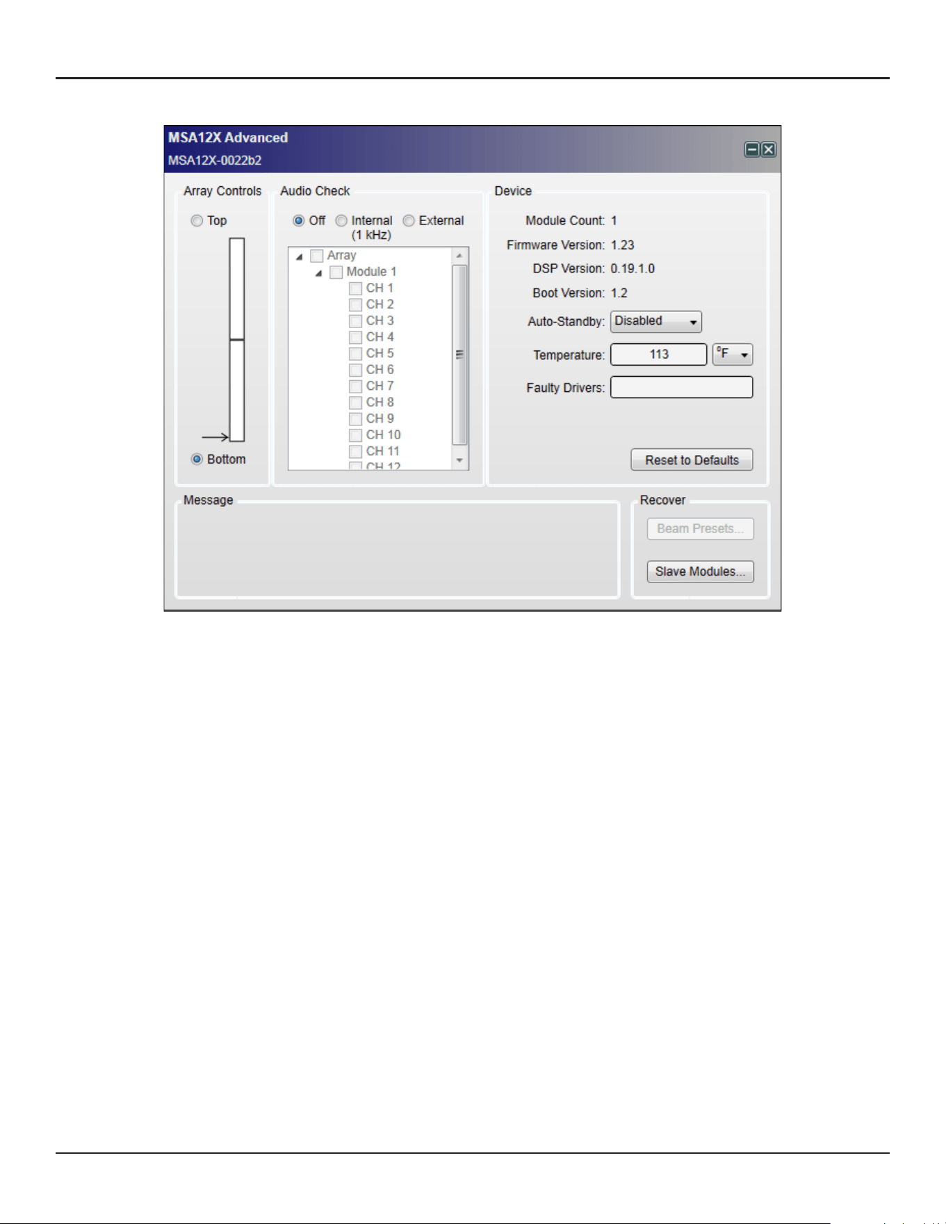
26 - Design Guide Design Guide - 27
CSD Properties and OperationCSD Properties and Operation
Advanced Window
Array Controls
When you mount an MSA12X array on the wall, you can choose the orientation of the module(s) by
specifying the array end that has the RJ-45 and power input panel. This defaults to Bottom, and in this
situation, your RJ-45 and power cables enter the master module at the bottom. In some installations,
installers prefer to send the RJ-45 and power into the top of the array. In those situations, you should
select Top from this menu; you should physically invert the array so the RJ-45 and power inputs are at
the top (and don’t forget to rotate the Bose logo on the front grille). This software setting orients the
software so it knows if the master module is on the top or bottom, which way the arrays are oriented, and
can plan the beam types and steering correctly.
Audio Check
You can check each array/module/driver with either an internal or external audio signal. With Internal
option, an internal signal generator feeds 1 kHz sine wave to the device. This is useful to identify the array
even before subscribing Dante® routing.
Device
Module Count: Number of modules of the array.
Firmware Version
DSP Version
Boot Version
Auto-Standby: You can specify the signal absence time before the array goes to Standby mode. The array
recovers from Standby mode when the input signal is present for 6-10 seconds.
Temperature: Indicates the temperature of internal amplifier.
Faulty Drivers: Indicates the number of faulty drivers and/or amplifier channels that are shorted or with
excessive high current beyond the design’s capability.
Reset to Defaults: Clears all the stored beam presets and sets the array to factory default.
CSD Workflow
There are many dierent ways to configure a MSA12X system. In this document we describe an on-site setup
process. The assumption in this document is that you have an ESP with a Dante® card in the system, and the
IP address of the devices are already set. For guidance for IP setup, see Appendix.
Initial Configuration in Project View
1. Connect the PC to the network and launch CSD. A blank Project appears.
After 5-10 seconds (depending on the network status), MSA12X device blocks appear on the Project View.
Note: This is not related to the ControlSpace Scan.
MSA12X is a Dante device, and it is recognized and controlled by CSD even without the CSD Network Scan or
CSD Go Online. If an MSA12X device block does not appear,
Go to System > Enable Dante Control.
Make sure the PC and MSA12X array(s) are both connected to the network.
Make sure the IP address for both the PC and the MSA12X array(s) are set properly. For details, see
Appendix.
2. It is highly recommended to enable Endpoint Control prior to the following operations. When Endpoint
Control is disabled, Dante endpoints (including MSA12X) are under the control of the firmware of ESP
or EX-1280C, and you cannot program MSA12X controls from CSD. If Endpoint Control is disabled, many
of the controls of the MSA12X control panel will be grayed out and a warning message will be indicated.
Endpoint Control is disabled by default.
To enable Endpoint Control, go to System > Enable Endpoint Control.
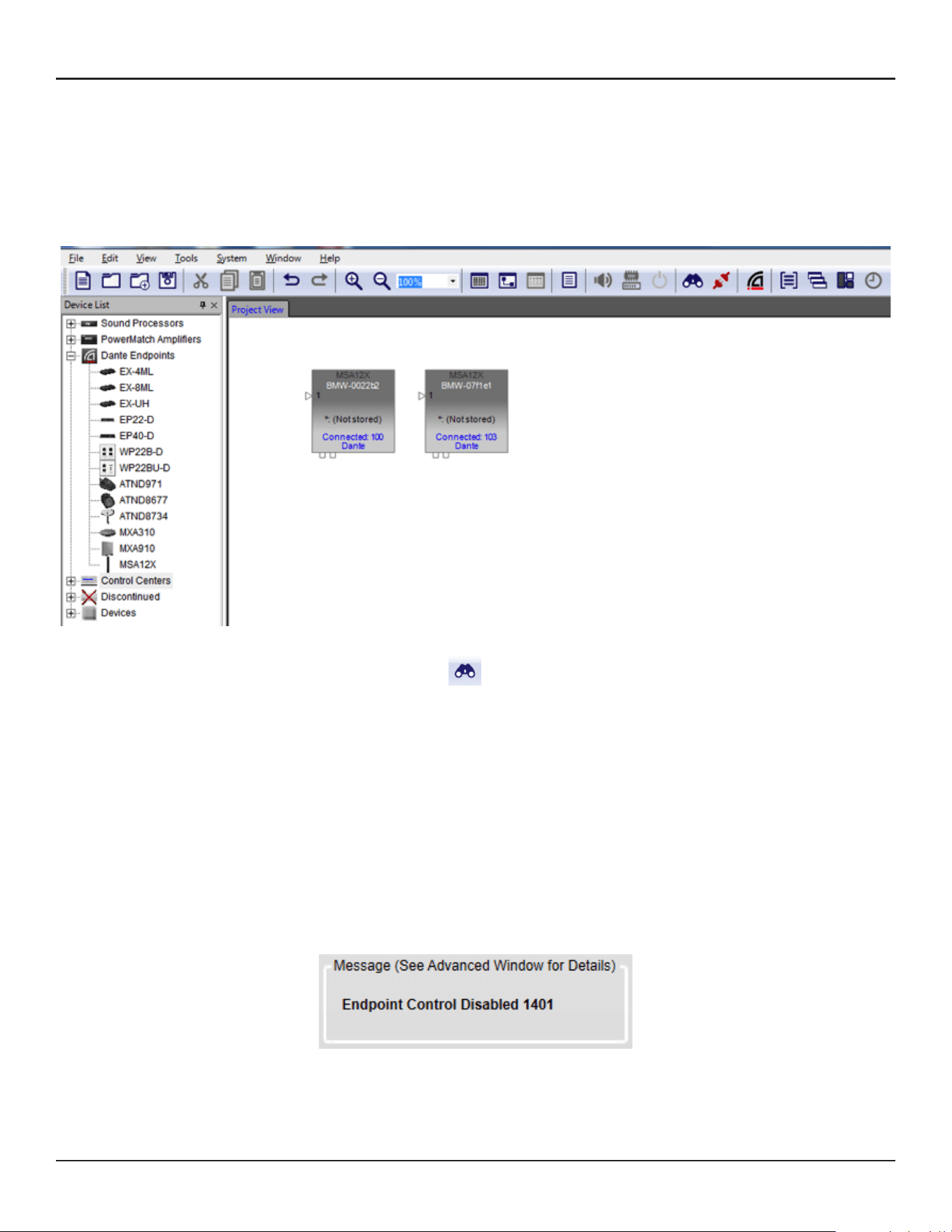
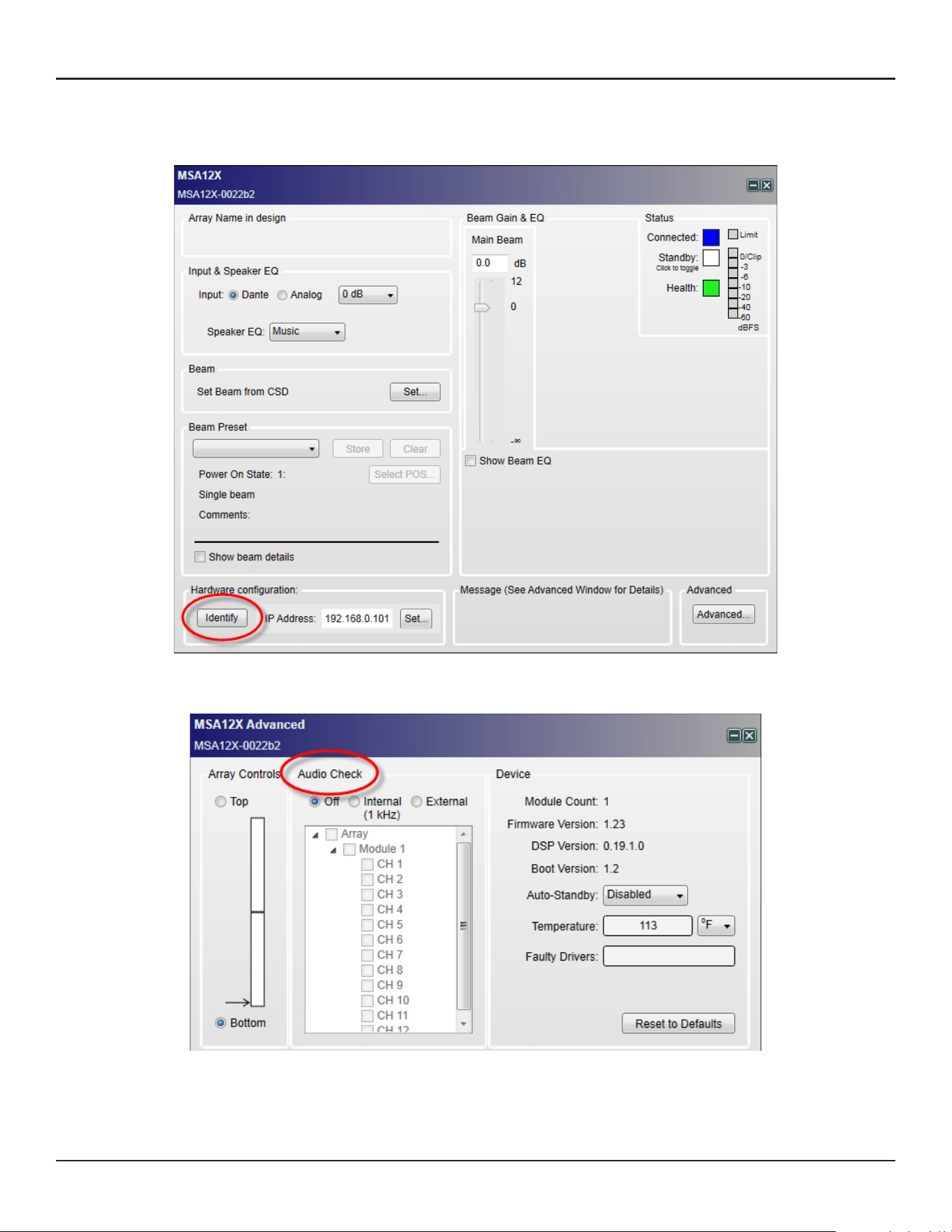
28 - Design Guide Design Guide - 29
CSD Properties and OperationCSD Properties and Operation
3. The next step is to identify which MSA12X device block represents which physical array on the network. To
do this, double-click the device block and open the MSA12X control panel, and press the ‘Identify’ button at
the bottom. An LED at the back of the physical array flushes and you can identify the device block.
If you cannot access the back of the array to see the LED, another option is to push ‘Advanced…’ button and
use the Audio Check mode.
With the ‘Internal’ option, an internal signal generator feeds a 1 kHz signal to the array and the array can be
identified by that sound.
4. Once you identify the array, rename the device, such as ‘Left-Array, ‘Right-Array. This is the device name
used for Dante® routing later. The device name can be the same as the Array name already defined in
Modeler, but they can be dierent.
You can rename the device by right-clicking the device icon in the Project View.
Note: The device name should follow the rule for Dante device labeling: Legal characters are A-Z, a-z, 0-9, and
‘-’ (dash or hyphen). Device labels must begin with A-Z (or a-z).
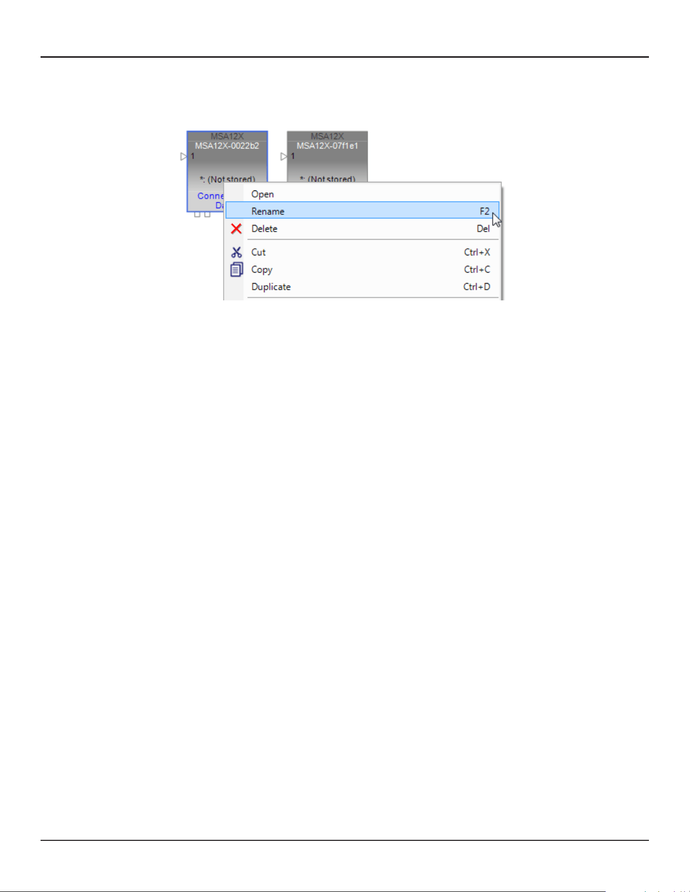
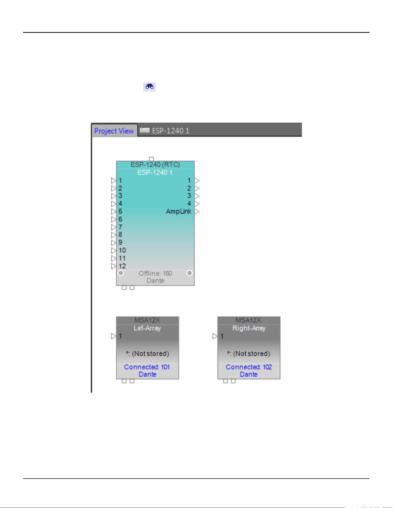
30 - Design Guide Design Guide - 31
CSD Properties and OperationCSD Properties and Operation
Associate ESP and MSA12X
In order to set multiple beam patterns for an MSA12X array and invoke changes from external devices, such as
a Bose CC-64 controller, you need a supported Bose ControlSpace processor. Then, associate the MSA12X to
the ControlSpace processor in CSD. Also through this process you can setup Dante® routing. If you use analog
for your audio signal and do not need to set/invoke multiple beam patterns, you can skip this section.
1. Scan the network with CSD Scan.
2. An ESP device block appears on the Project View.
3. Double-click the ESP device block and go to the device view of the ESP. Now you see MSA12X devices in
the list under Dante Endpoints in the SP Tool Kit. Drag-drop these devices from the SP Tool Kit into the
device view. This means that these devices are associated with the ESP currently selected.
4. When you drag-drop the devices from SP Tool Kit, red blocks appear in the Device View. These represent
the Dante output blocks for the MSA12X devices. Notice you have two output channels for each MSA12X
array. These 2 channels correspond to the two beams when the array is in dual beam mode; Ch1 is for Main
Beam, and Ch2 is for Secondary Beam. If the array is in Single beam mode, signal for Ch2 is not radiated
from MSA12X array.
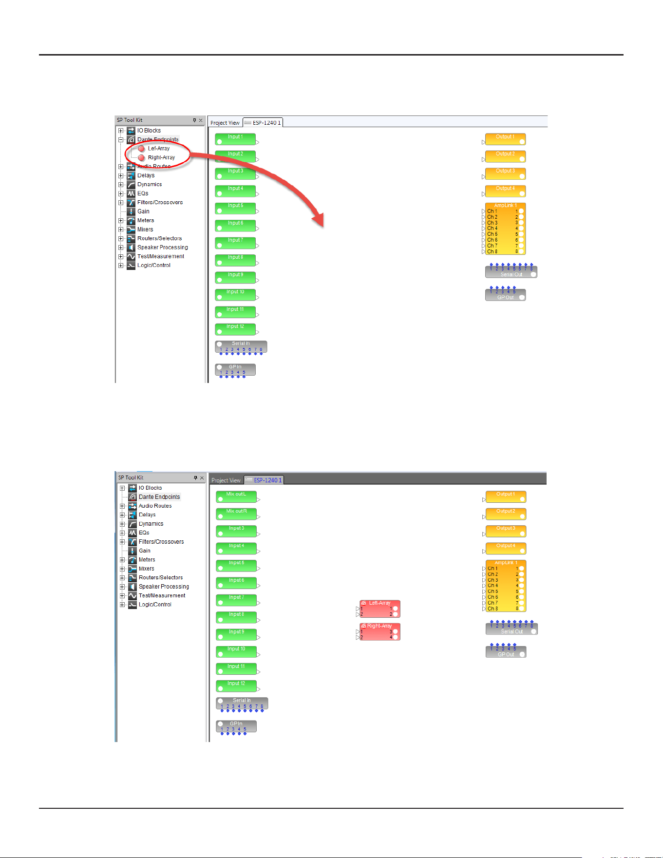
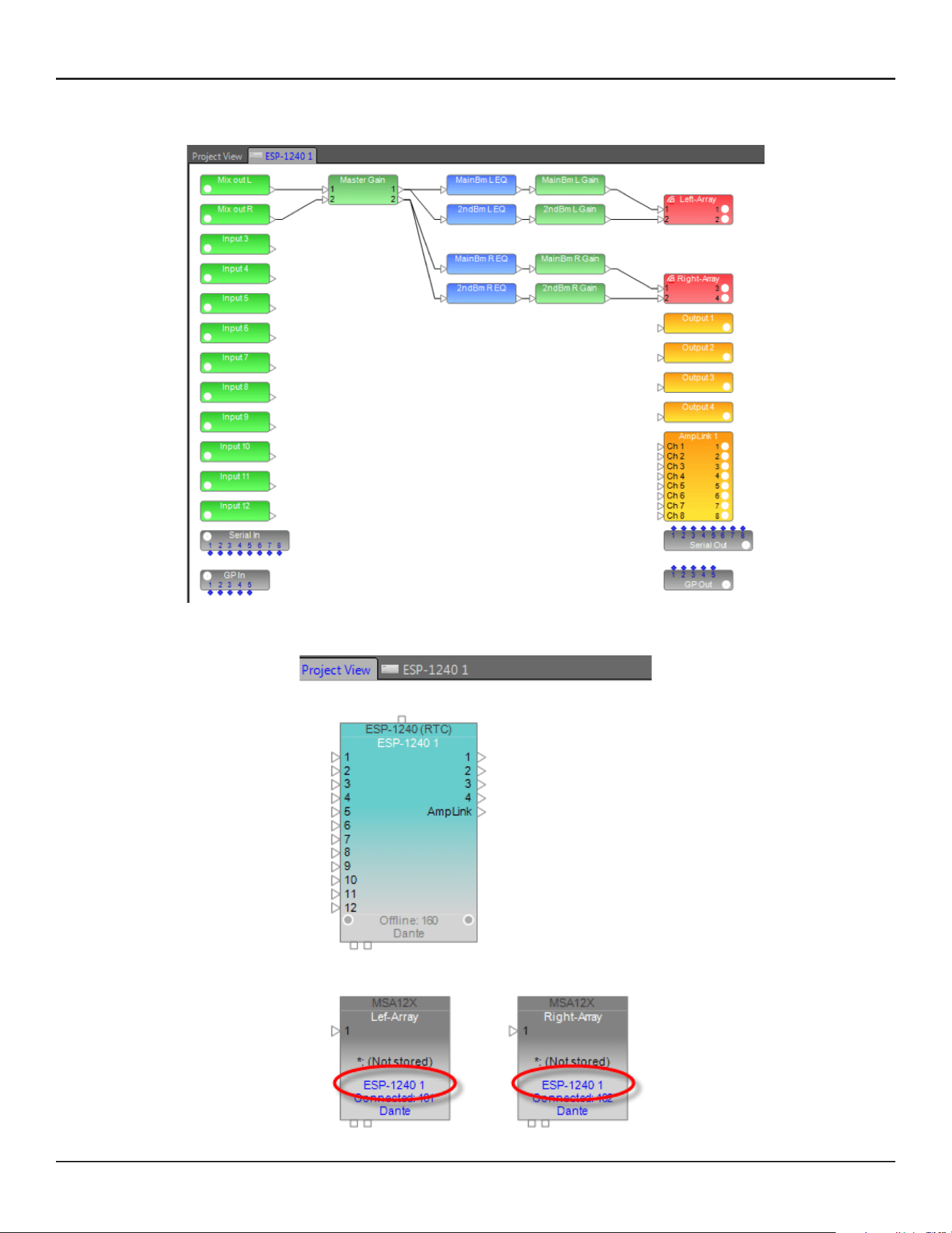
32 - Design Guide Design Guide - 33
CSD Properties and OperationCSD Properties and Operation
5. Add other signal processing blocks in the Device view and complete the system. You can apply dierent
gain/EQ for each beam by feeding signals for output 1 and 2 of each MSA12X array.
6. Go back to the Project View. Now the MSA12X device block indicates the ESP that it is associated with.
Dante® Subscription
When MSA12X is associated to an ESP, Dante channel subscription from the ESP to the MSA12X is executed
automatically. Open the Dante Properties window by clicking the Dante icon ( ) in the tool bar (or select
from System > Dante Properties...) to see that Dante channel subscriptions have already been made.
The Dante channel subscription can also be changed manually.
Adjust Input Settings
Adjust input settings to match your system. In the MSA12X control panel, you can
Select input type from Dante or Analog.
Select input gain (0 dB / +14 dB / +24 dB).
Select Speaker EQ (Music or Voice).
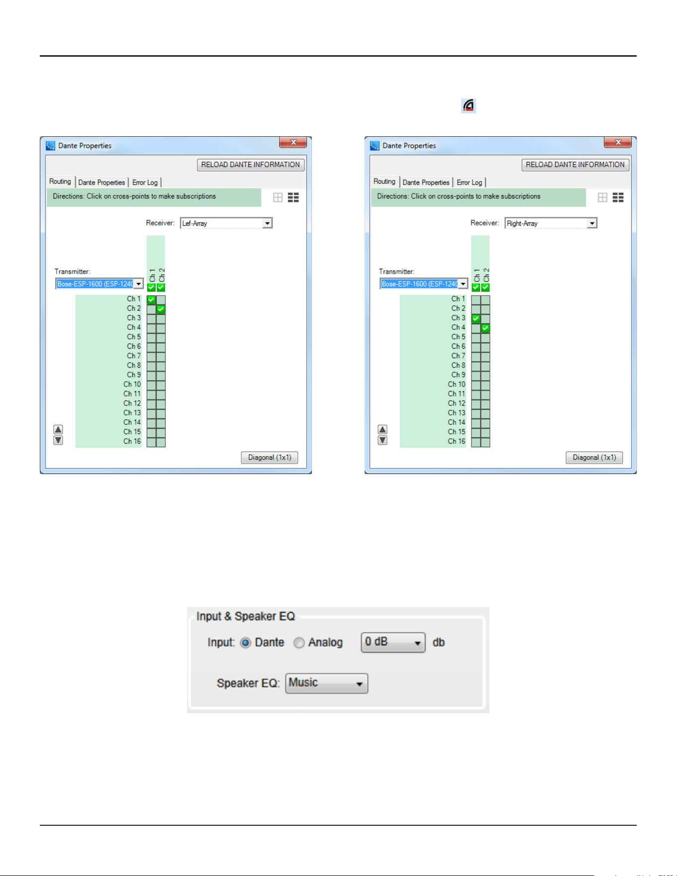
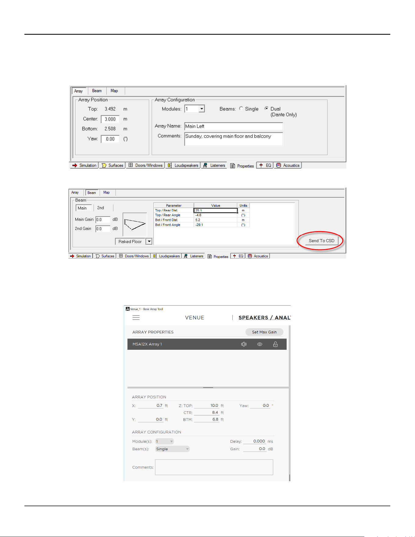
34 - Design Guide Design Guide - 35
CSD Properties and OperationCSD Properties and Operation
Send Beam Settings from Bose Array Tool or Modeler
Now you are ready to send beam settings designed in Bose Array Tool or Modeler to the MSA12X arrays.
1. Go to Modeler. Select the array and go to the Properties tab. Make sure the number of Modules (module
count) in the Array Configuration matches that of the physical array.
2. Go to the Beam tab and click the ‘Send to CSD’ button.
Send Beam Settings from the Bose Array Tool
1. Go to Bose Array Tool. Design your Array in the Speakers/Analysis tab. Make sure the number of
Modules (module count) in the Array Configuration matches that of the physical array.
2. Go to the Beam tab and click the ‘Send to CSD’ button.
Note: CSD should have been launched on the same PC.
Receive Beam Settings within CSD
Beam Configuration Destination dialog box appears. The arrays
that are selectable in this dialog box are the ones with the same
number of modules (module count) in CSD. The number in
parentheses after the device name indicates the module count.
If the module count does not match, you cannot send beam
settings to the array.
You can select multiple devices if needed. This is helpful when
you have multiple arrays that require the same beam settings.
Now the beam setting has been sent to the array. If you are
feeding audio signal to the array, you will be able to hear the
beam pattern change. If you do not like the coverage, go back
to Modeler or Bose Array Tool, adjust the parameters and repeat
this process.
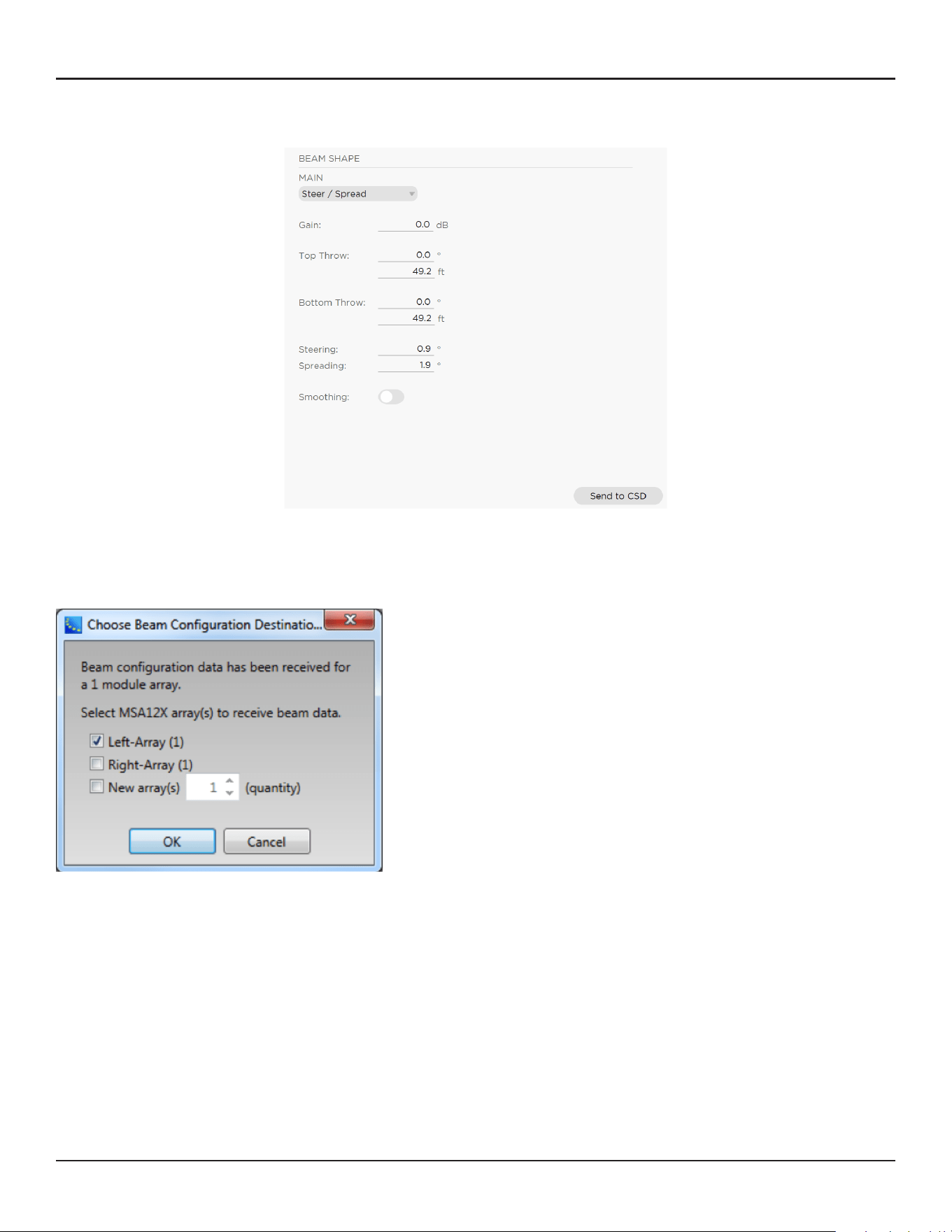
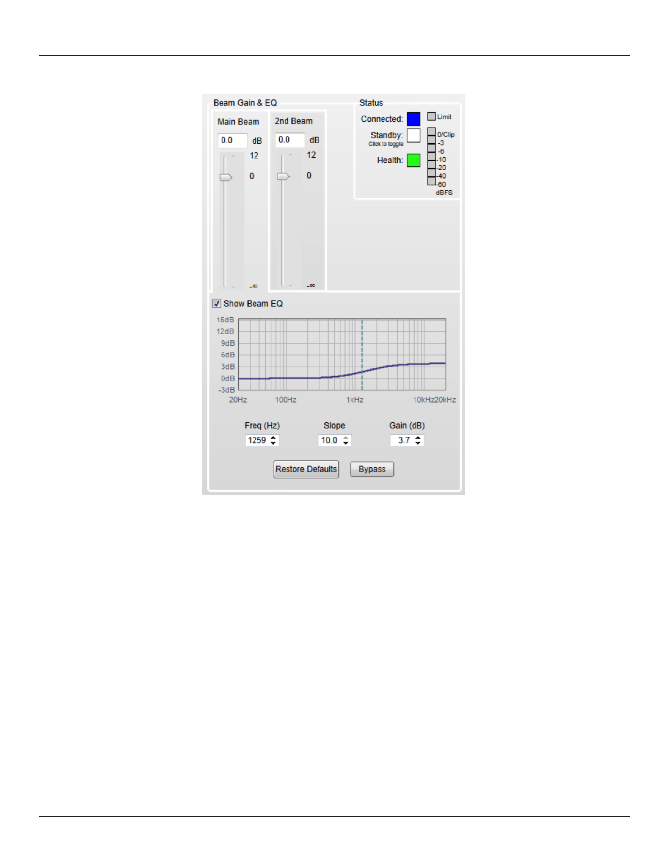
36 - Design Guide Design Guide - 37
CSD Properties and OperationCSD Properties and Operation
Adjust Beam Gain and Beam EQ
The Beam Gain and Beam EQ can be changed.
Beam Gain is for balancing gains between two beams when in Dual Beam mode.
Note: Beam gain cannot be assigned to ControlSpace wall panels, such as CC-64 or ControlSpace Remote.
Beam EQ is a filter to compensate for the tonal balance change depending on the beam spreading. The Beam
EQ curve is calculated in Modeler for each beam automatically, and sent to CSD. The shape of the curve can
also be adjusted. By clicking the beam gain for each beam, the Beam EQ display is toggled for that beam.
Beam Preset and Power On State
When you are satisfied with the coverage, Beam Gain and Beam EQ, the next step is to store that beam
pattern to the array. Unless you store the beam pattern to a Beam Preset, the beam pattern is lost after the
power cycle of the array. There are 10 memory banks for each MSA12X array, and you can store up to 10
dierent beam patterns along with other hardware properties (Beam Preset) to each MSA12X array. Beam
Preset is a ‘snapshot’ of the state of the array.
Items below are stored in a Beam Preset:
Input type, Input gain
Speaker EQ
Beam parameters such as Steer Angle, Spread Angle, etc.
Comments
Beam Gains
Beam EQs
Store Beam Preset
1. Click ‘Store’ button.
2. Store Beam Preset dialog box appears. Select the Preset number that you want to store the current state
to. Change the label for that Preset. You can also edit the Comments field (up to 50 characters).
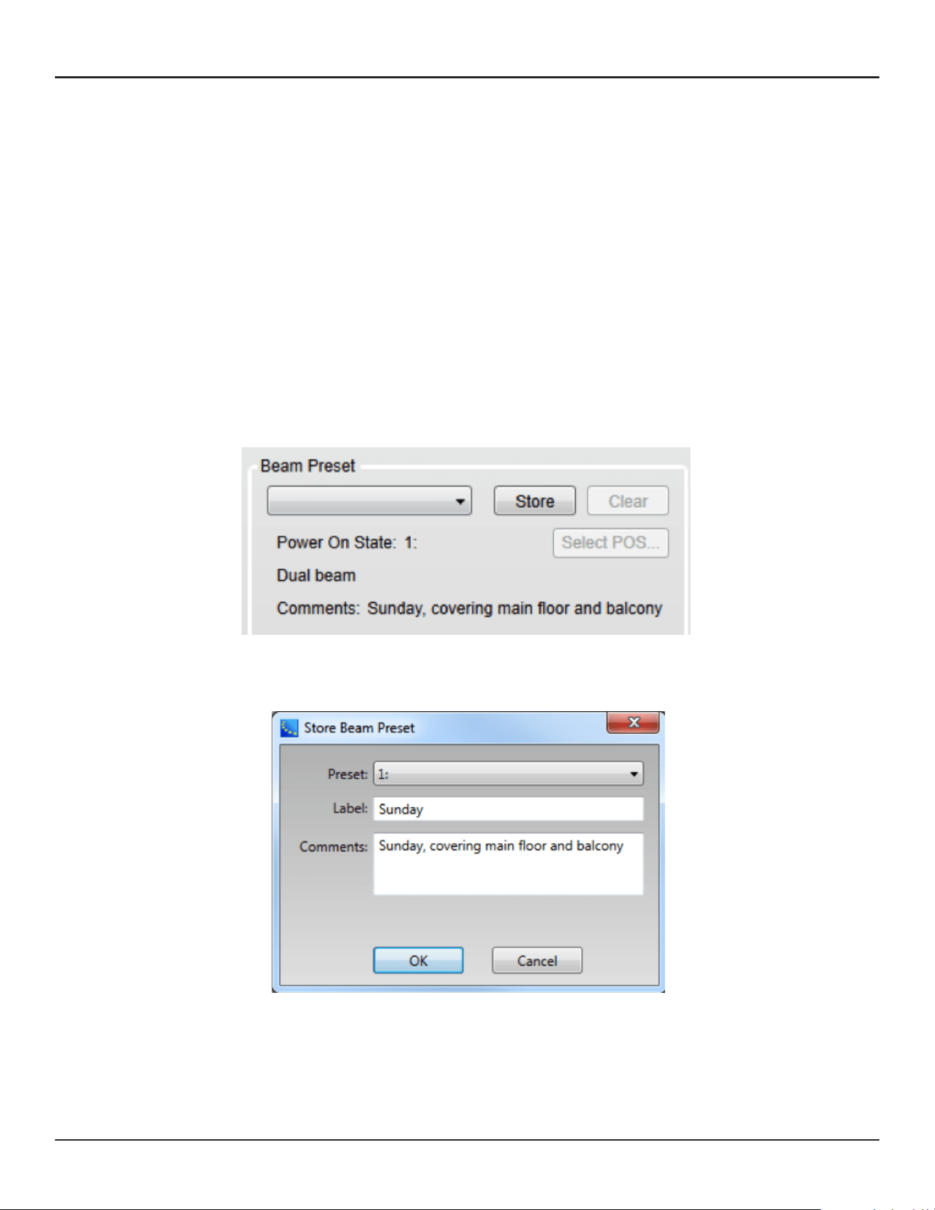
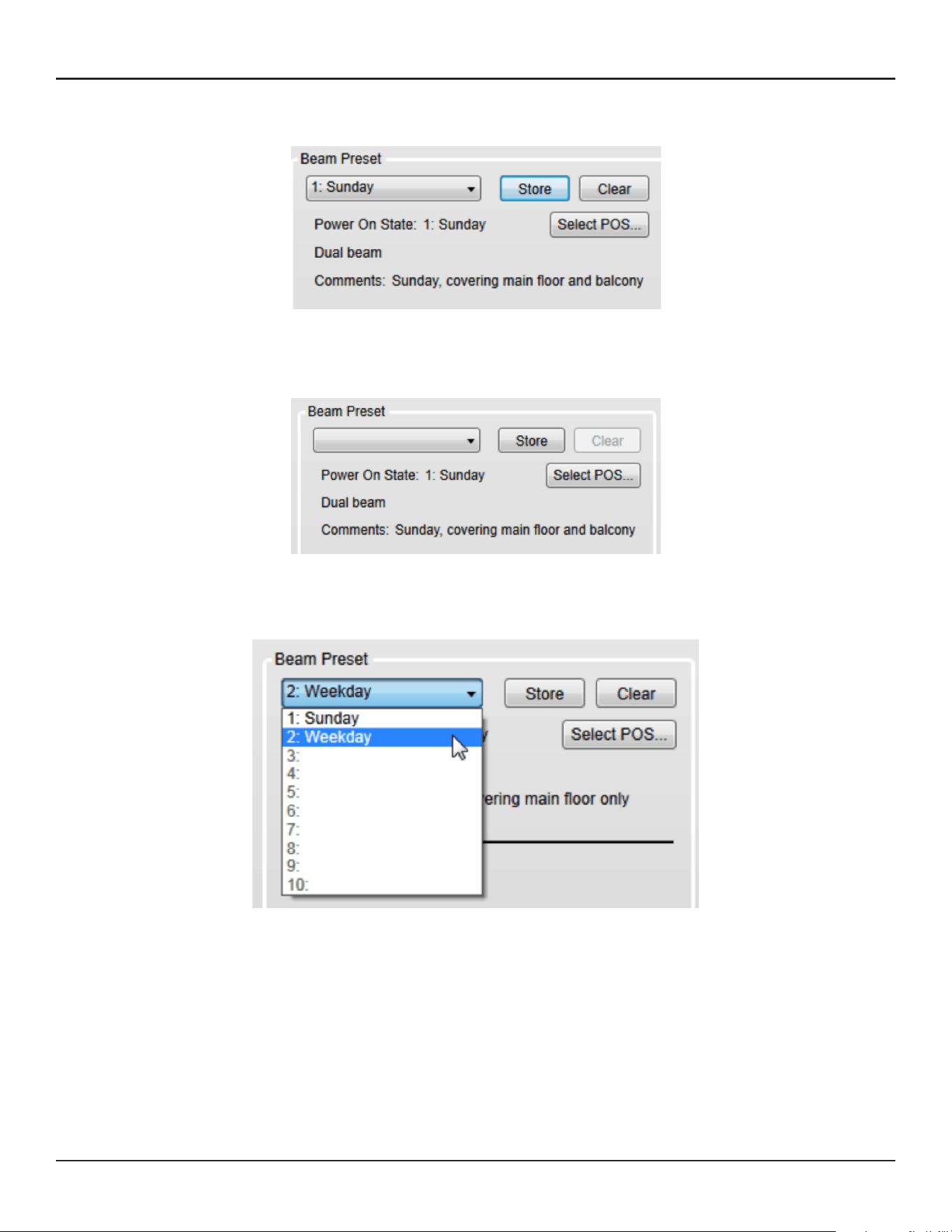
38 - Design Guide Design Guide - 39
CSD Properties and OperationCSD Properties and Operation
3. Now the current state is stored to the selected Preset. You can see the currently selected preset on the
Beam Preset menu (‘Preset 1: Sunday’ in this case).
4. If you change any parameter (such as Beam pattern, Beam Gain) from here, the Beam Preset menu
becomes blank. This means that the settings have changed, and the current state of the array has not been
stored to a Beam Preset.
Above: Menu becomes blank after changing Beam EQ.
5. Once you store a beam preset(s), you can recall that beam preset from the drop-down list.
Power On State
Power On State is a Beam Preset that is automatically recalled right after the power cycle of the array. By
default, the first stored Beam Preset is assigned to the Power On State. The Power On State is indicated
below the Beam Preset menu.
You can change the Power On State to a dierent Beam Preset.
1. Click ‘Select POS…’ button
2. Select Power On State dialog box appears. Select the Beam Preset that you want to assign to the Power
On State.
3. Click OK. Now the Power On State has been changed.
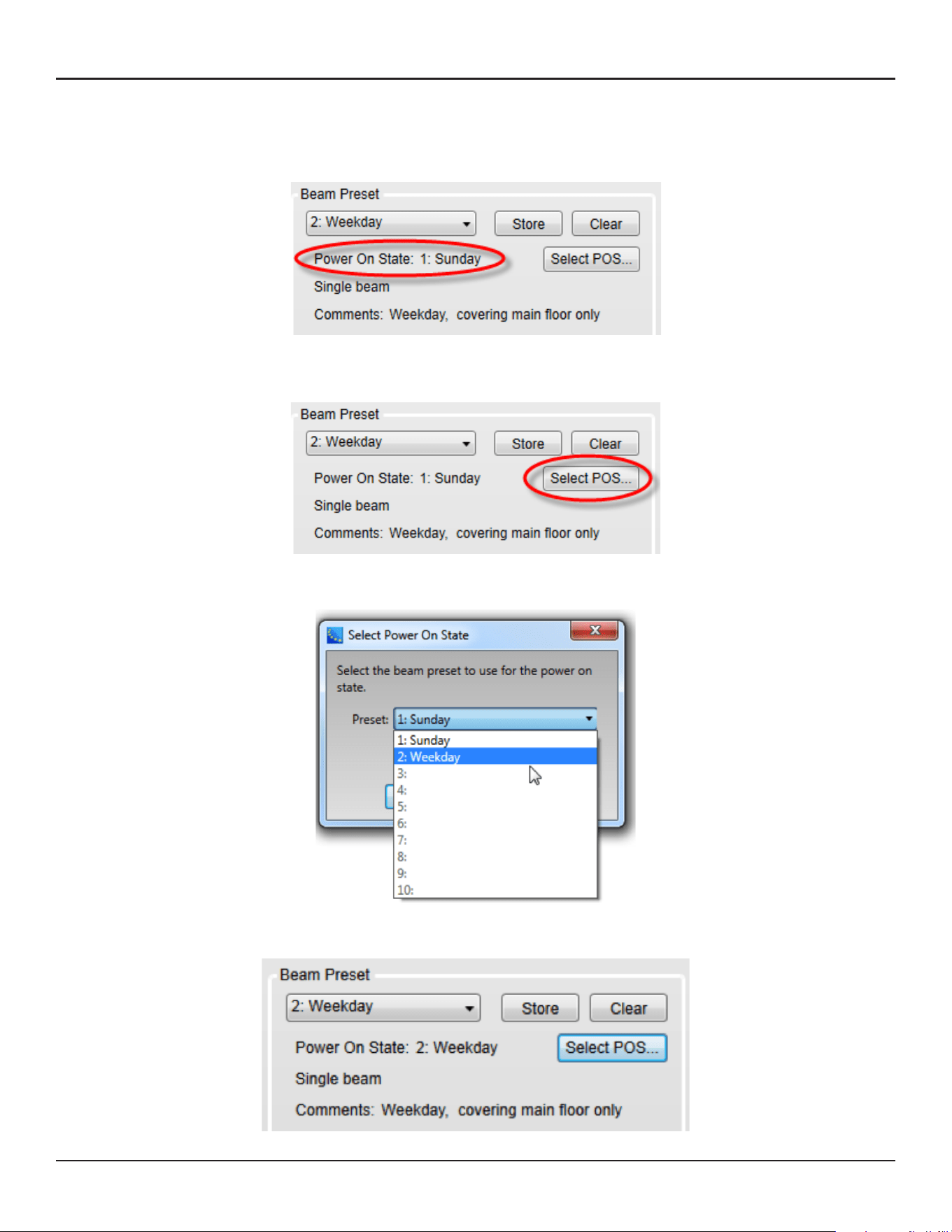
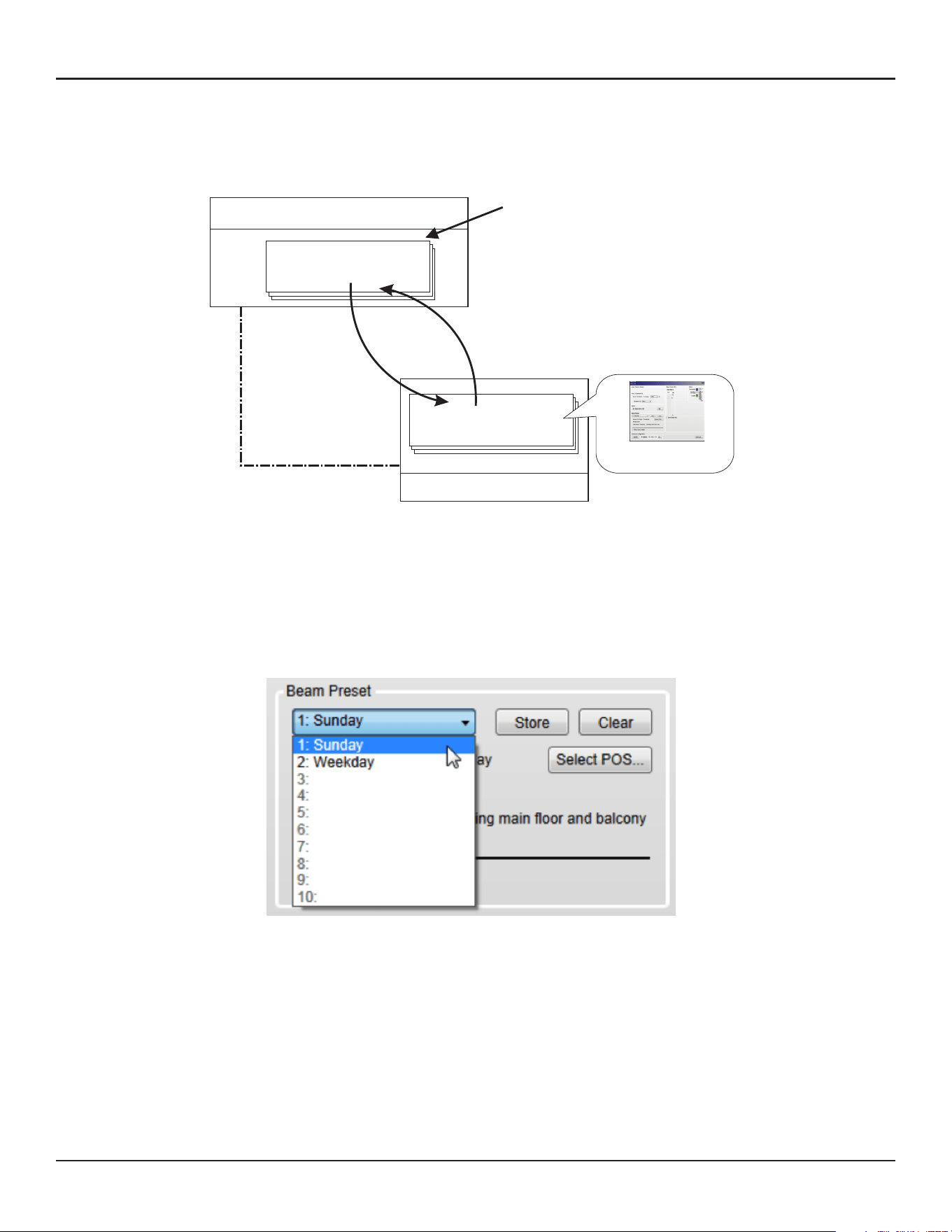
40 - Design Guide Design Guide - 41
CSD Properties and OperationCSD Properties and Operation
Assign Beam Preset to Parameter Set
Once you assign Beam Presets for each array, you can recall a Beam Preset by invoking a Parameter set from
other ControlSpace control families (such as CC-64, GPIO, Timer in ESP, ControlSpace Remote). To do this,
you have to assign the Beam Preset to the Parameter set.
Note: You cannot assign each individual Parameter of an MSA12X device (such as Beam Gain, Beam EQ) to a
Parameter set directly. Only a Beam Preset (which is a ‘snapshot’ of the state of the array) can be assigned to
and recalled from a Parameter set.
This operation can be done while Dante is enabled, but cannot be done when CSD is online (blue
background), which is a standard CSD programming procedure. You have to go oine before setting
Parameter sets.
1. Recall the Beam Preset for the state that you want to assign to a Parameter set.
ESP/EX-1280C processor
Parameter Set
Beam Preset
Associate
MSA12X loudspeaker
Assign Beam Preset
to Parameter Set
Recall
Snapshot of status
Invoke Parameter Set with
- CC-64
- GPI trigger
- ControlSpace Remote
...etc.
2. Go to the device view of the ESP that the MSA12X device is associated with, and select the output block
that represents the MSA12X device.
3. Drag that output block into the parameter set tree in the Parameter Set window. Rename the parameter
set if needed.
4. Select Properties window appears. Select ‘Endpoint properties’. Click OK.
5. Now the Beam Preset has been assigned to the Parameter set.
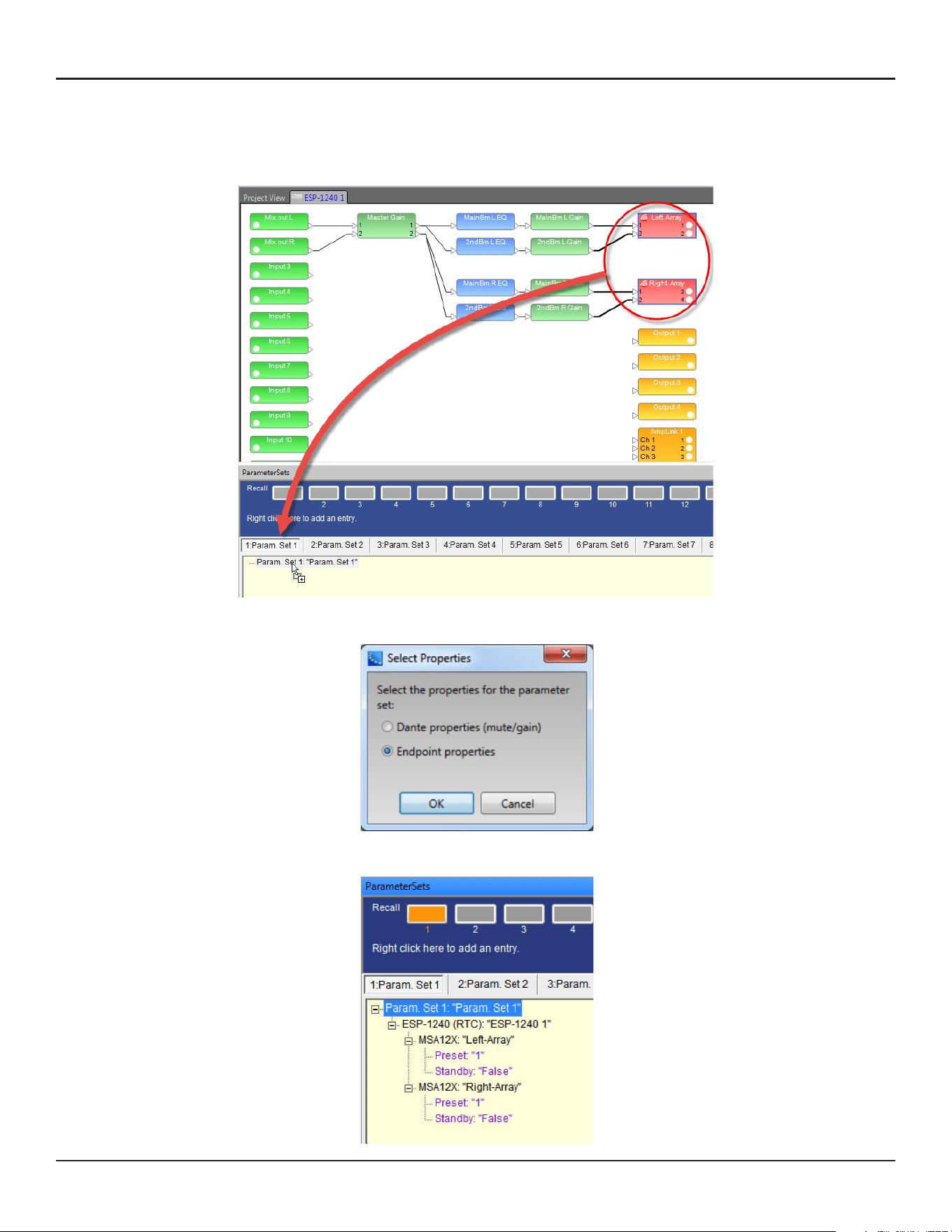
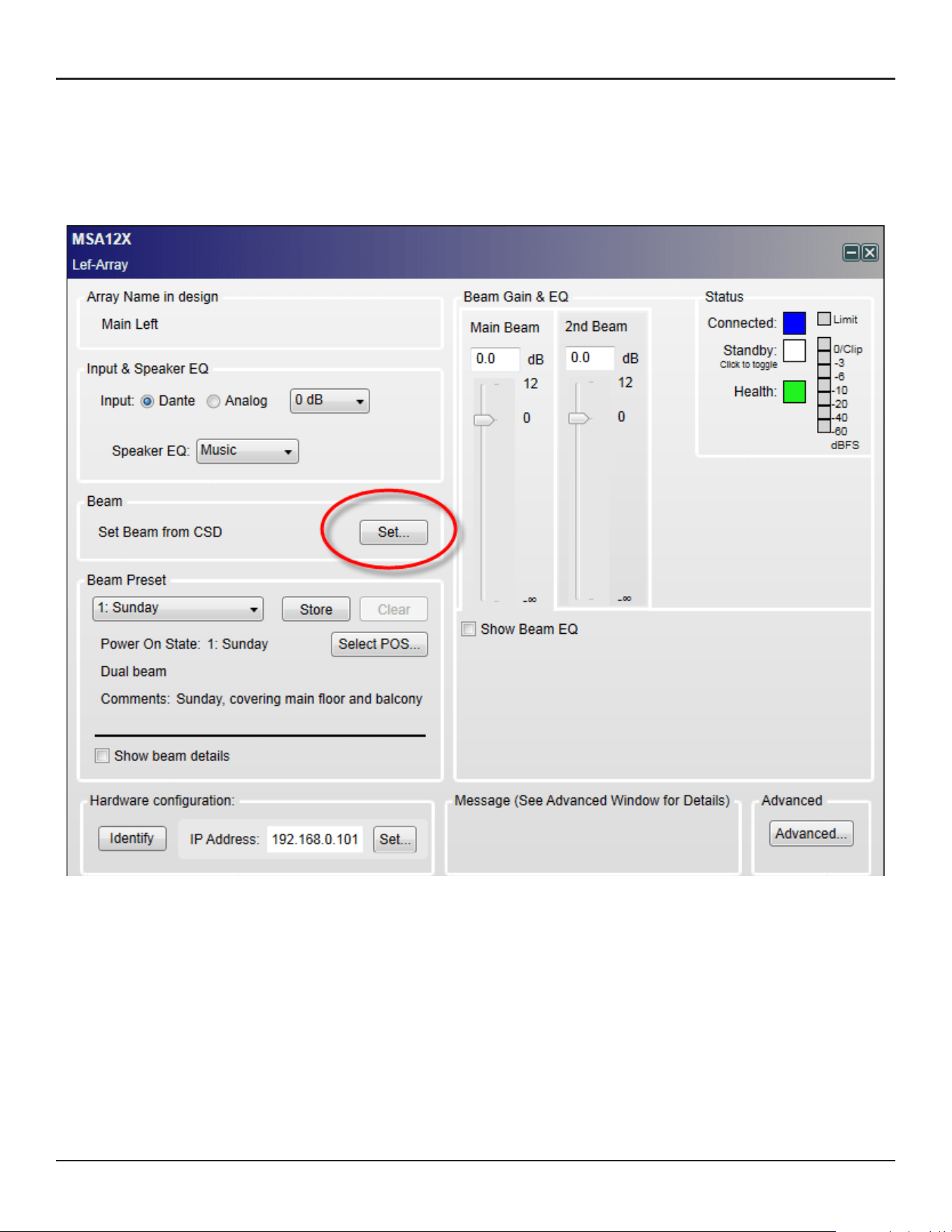
42 - Design Guide Design Guide - 43
CSD Properties and OperationCSD Properties and Operation
Beam Shaping in CSD
You can set the Beam Shaping within CSD for Basic Steer/Spread without needing Modeler on your PC. This
is helpful when you set the beam in a room that requires only basic steering and spreading without the visual
guide from the Vertical SPL map of Modeler.
1. Click ‘Set…’ button under Beam.
2. Beam Control window appears. Set the Steer angle and Spread angle for each beam. A red wire frame
corresponds to the Main Beam; a blue wire frame corresponds to the Secondary Beam. ‘Vocal Smoothing
Option’ is not available for this tool. Press ‘Set’ when you finish.
Note: The beam wireframes may look dierent from those in Modeler, even when the steering (and/or
spreading angle) is the same. This is because in Modeler, a user can specify the Distance (length) of the beam
lines, which does not aect the beam of this beam type. As long as the steering (spreading) angle is identical,
the radiated beam pattern is identical.
3. Now the beam pattern is transferred to the array, and you will be able to hear the change of the beam
pattern. If you like this pattern, store it to a Beam Preset (see page 35).
This function is available when either
The MSA12X device in CSD is already associated to a Physical array.
The MSA12X device in CSD has already received a beam pattern sent from Modeler.
Otherwise, the ‘Set…’ button is grayed out.
Template Files
Template files will be available on PRO.BOSE.COM to get you started using CSD and Modeler with MSA12X.
These will include arrays for typical systems, including a 2-module Left-Right system with a single beam and
a 2-module Left-Right system with dual beams. If you are new to CSD or Modeler, it is recommended to use
these template files to start your projects.
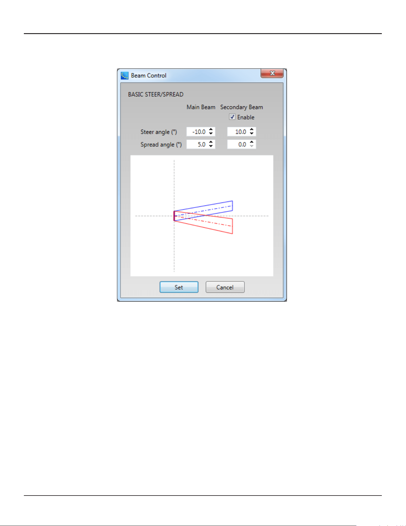
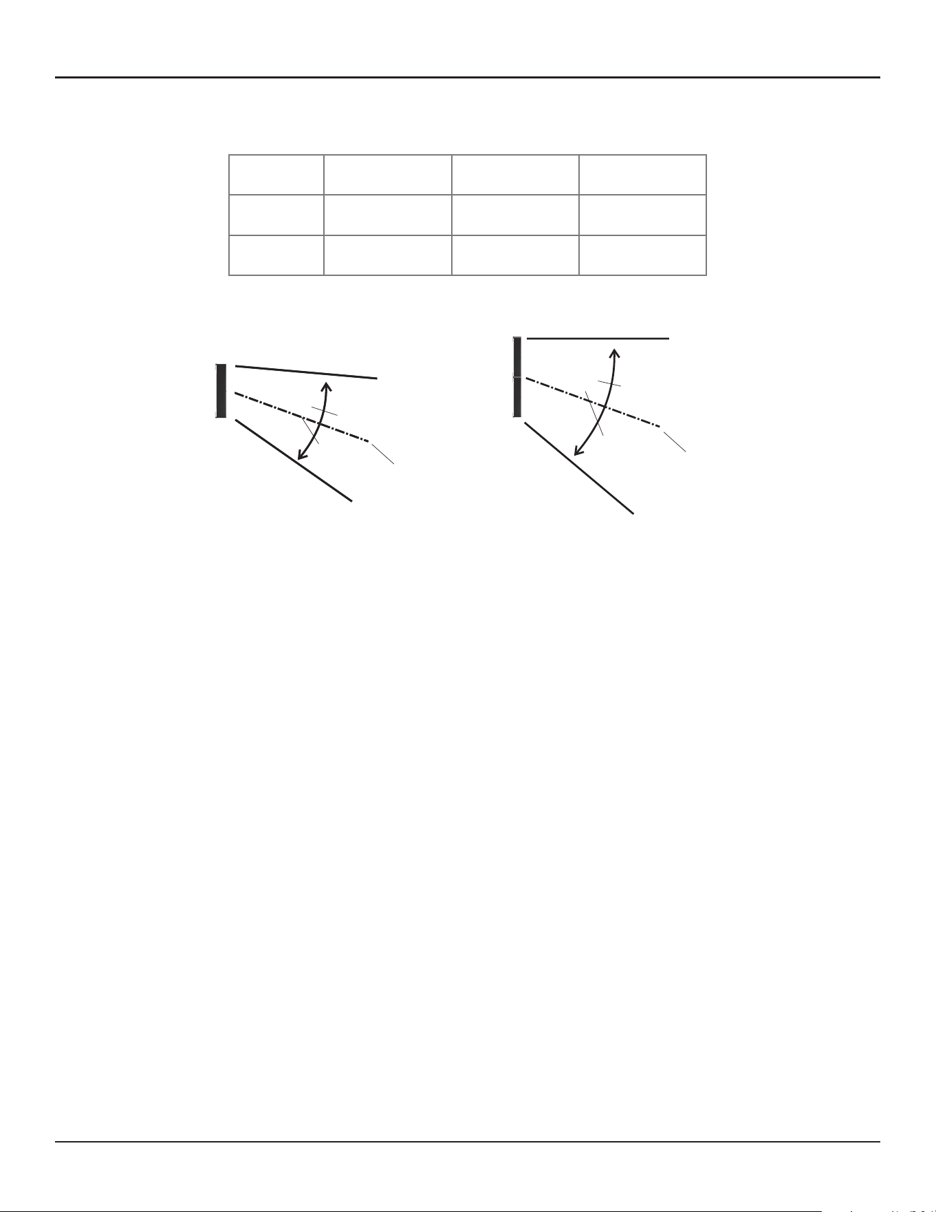
44 - Design Guide Design Guide - 45
Frequently Asked QuestionsFrequently Asked Questions
Frequently Asked Questions
What is the angular limit for Basic Steering/Spreading?
Array 1-module 2-module 3-module
Steer –20° to +20° –20° to +20° –20° to +20°
Spread 0° to 30° 0° to 40° 0° to 40°
What is the frequency limit for the beam control?
It depends on the length of the array. The longer the array, the lower the frequency limit for the beam control.
A rough guide is shown below:
1-module array: 500 Hz
2-module array: 250 Hz
3-module array: 160 Hz
How many modules per array are supported?
Up to 3 modules stack per array is supported.
How many modules do I need for the dual beam?
Regardless of number of modules of an array, up to two beams (single beam or dual beam) can be radiated. It
is recommended to use a 2- or 3-module MSA12X array for better directivity control due to the longer array.
How many beams can be radiated from one array?
Currently, up to two beams per array (dual beam) are supported.
Do I need a power amplifier for driving a MSA12X array?
No. MSA12X is a powered loudspeaker with amplifiers in it, and you do not need additional power amplifiers.
Does MSA12X have DSP inside? Do I need an external signal processor?
MSA12X has on-board DSP inside, which manages Speaker EQ, beam shaping, beam gain and Beam EQ. If you
need to apply more signal processing such as Room EQ or signal delay for rear arrays, you need an additional
signal processor such as Bose ESP in the upstream of the system.
1-module array
Steer: ± 20°
Spread: Up to 30° (± 15°)
−20°
15°
15°
2- or 3-module array
Steer: ± 20°
Spread: Up to 40° (± 20°)
−20°
20°
20°
30°
40°
Ear
Height
0.3-0.8 m
(1’-2.5’)
Max Recommended
What EQ options does MSA12X oer?
MSA12X has 2 layers of EQ in its on-board DSP. First, it has an on-board Speaker EQ, with a Music and Speech
option that updates for 1-module, 2-module and 3-module arrays. This provides the basic sound profile for
MSA12X and the Music setting closely matches the MA12EX sound profile. Second, there is Beam EQ which
compensates for the tonality change when spreading is applied. Beam EQ is automatically applied by the
beam shape and this can be viewed and edited in the CSD MSA12X control panel. And optionally, a third layer,
room EQ can be added to correct for room problems. This EQ is manually added as blocks in a DSP such as
ESP-880/1240/4120/1600 or ControlSpace EX-1280C. Template CSD files include the recommended room EQ
blocks for CSD.
Do I need Speaker EQ on external signal processor?
No. MSA12X has an on-board Speaker EQ, which you can choose from ‘Music’ or ‘Voice’.
What is possible with/without a ControlSpace ESP, with/without Dante® Card?
ESP* with Dante Card,
ControlSpace EX
ESP* without
Dante Card
No ESP
in the System
Input Signal Dante or Analog Analog Analog
Beam Pattern Change** via
CC-64 and Bose wall controls
Yes No No
Beam Pattern Change** via
ControlSpace Remote (CSR)
Yes No No
Beam Pattern Change** viaTimer Yes No No
Beam Pattern Change** via GPI Yes No No
Toggle Stand-by via Bose wall
panels, CSR, Timer, GPI
Yes No No
Dual Beam Yes No No
Room EQ, delay Use ESP* or
ControlSpace EX
Use ESP* Requires 3rd
party processor
* ControlSpace ESP-880, ESP-1240, ESP-4120, ESP-1600 engineered sound processors
** Includes Dante/Analog input, input gain, Beam EQ settings
What is the input signal type?
Dante input and balanced analog input are supported.
Can I use Dante redundancy with MSA12X?
MSA12X array has only one RJ-45 input, and Dante redundancy is not supported. Note that for a multi-module
array, you cannot use RJ-45 input(s) that belongs to slave module(s). Only the RJ-45 input on the master
module can be used for the entire array.
Can I switch Dante/Analog input without a PC?
Yes. To do this, you need an ESP (with Dante Card) or EX-1280C in the system. Input type (Dante/Analog) can
be stored in the beam presets. Once you set up the beam pattern, first store that beam pattern to one of the
beam presets, with ‘Dante’ selected for the beam type. Then switch the input type to ‘Analog’, and store that
state to another beam preset. Assign these beam presets to Parameter sets in ESP/EX-1280C. You can now
switch between Dante input and Analog input using the Parameter sets.
Automatic failover is not supported.
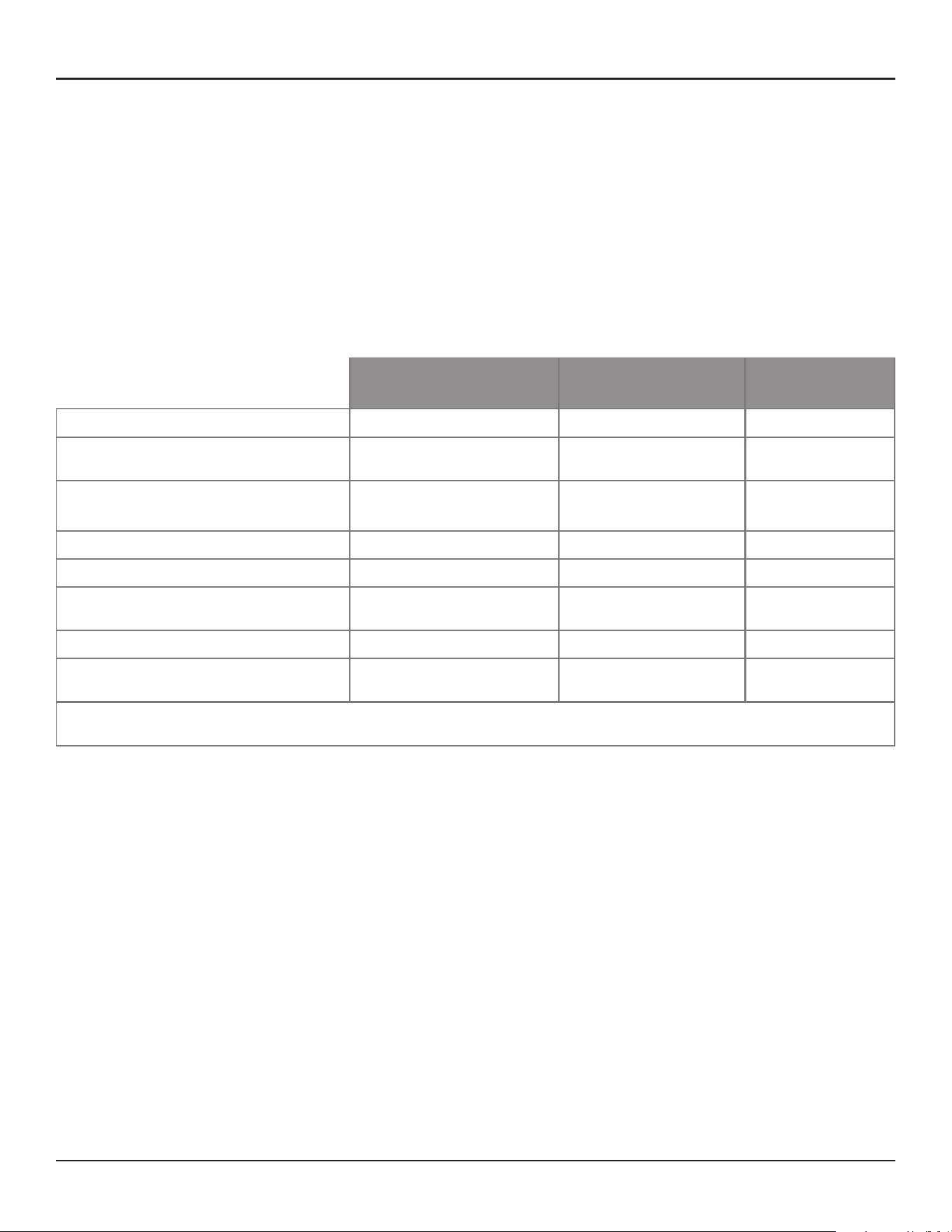

46 - Design Guide Design Guide - 47
Appendix: How to Set Up IP AddressFrequently Asked Questions
Can I assign Beam gains to controls such as CC-64 or ControlSpace Remote?
You cannot assign beam gains in the main window of MSA12X device view. In order to achieve the same
functionality, you need a supported ControlSpace processor. Insert a gain block in the signal chain in the ESP
(with Dante® Card) or EX-1280C and assign that gain block to the controls.
Can the ControlSpace ESP-00 processor be used to support MSA12X?
You can use ESP-00 and MSA12X in the same system. However, ESP-00 does not support association with
MSA12X. i.e. you cannot use Parameter Set via ESP-00 for invoking Beam Preset of a MSA12X array.
Can I use the beam shaping functionality from CSD?
Yes, with a specific beam type. In CSD, you can use ‘Set beam from CSD’, which enables you to setup basic
steering/spreading on site without needing Modeler.
Can I use rear arrays? When do I need rear arrays?
You can use rear arrays just like when you design your system with line arrays such as MA12 or MA12EX. This
will depend on the room shape and beam pattern that you design. It is recommended to use the Modeler SPL
map and evaluate the acoustic performance based on the prediction.
Can I mix & match MSA12X with other Bose modular columnar arrays?
Yes. MSA12X is a member of the Bose Panaray modular line array family, which includes MA12 and MA12EX.
For example, if you do not need to digitally steer the beam for rear arrays, you can use other passive modular
line arrays with an amplifier (e.g. MA12 with a PowerMatch).
Does Bose oer an EASE .GLL file or EASE .GLL export for MSA12X to compare MSA12X performance
directly against competitors within EASE or EASE Focus?
No, Bose does not oer an Ease .gll file at this time. It is possible to import .CLF files in Modeler, however.
Does MSA12X oer Redundant Dante or Redundant Spillover from Dante to Analog in the case of a
Dante failure?
No, Bose does not oer redundancy support at this time.
Is MSA12X EN-54-24 certified for voice-alarm systems?
No, Bose does not oer EN54-24 support at this time.
Does MSA12X bracket and software allow physical pitch?
No, included bracket will not allow you to vertically angle the MSA12X. However, Modeler software can
accommodate physical pitch if it exists due to room dimensions.
How does MSA12X achieve such low dealer-prices compared to competitor beam-steering arrays of
the same height?
The modular design allows us to stock the product like a normal higher-volume SKU; customers can order
2 or 3 and stack them if they need a taller column. Furthermore, putting some of the duties of DSP into an
outboard DSP, specifically optional room EQ, allows a simpler design of the product.
Is the Panaray MSA12X modular line array loudspeaker paintable?
Yes, with Krylon® spray paints or other similar products.
Appendix: How to Set Up IP Address
We recommend having a router or DHCP server in the system for setting up, which will make the setup
process simple and easy. However there will be cases where you do not have a router/DHCP server. This
appendix shows example IP setting processes for typical situations.
For more complex Network settings, please contact the IT representative personnel.
Note: Dante® Controller must be installed on your PC (download: https://www.audinate.com/).
With EX-1280C or 1U ESP with Dante® Card, No Router
1. Connect PC and all the devices to the network.
2. Set IP of PC to DHCP.
3. Launch Dante Controller.
a. Make sure all the Dante Devices (incl. MSA12X arrays, ESP) appear.
b. At this point, all the Dante Devices should be
i. IP: 169.254.xxx.xxx
ii. Subnet Mask: 255.255.0.0
4. Change IP of all the Dante devices to static:
i. IP: 192.168.0.xxx (e.g. 101, 102, …)
ii. Subnet Mask: 255.255.255.0
Each time you change the IP, that Dante device may disappear in the Dante Controller, or even if it can be
seen, you may not be able to assign Dante subscriptions. This is OK.
Switch
MSA12X
MSA12X
Dante Card
ESP
PC
DHCP
IP: 169.254.xxx.xxx
Subnet: 255.255.0.0
DHCP
IP: 169.254.xxx.xxx
Subnet: 255.255.0.0
DHCP
IP: 169.254.xxx.xxx
Subnet: 255.255.0.0
DHCP
IP: 192.168.0.160
Subnet: 255.255.255.0
Dante Device IP automatically
given by Dante link local
DHCP
IP: 169.254.xxx.xxx
Subnet: 255.255.0.0
Switch
MSA12X
MSA12X
Dante Card
ESP
PC
DHCP
IP: 169.254.xxx.xxx
Subnet: 255.255.0.0
Static
IP: 192.168.0.102
Subnet: 255.255.255.0
Static
IP: 192.168.0.101
Subnet: 255.255.255.0
DHCP
IP: 192.168.0.160
Subnet: 255.255.255.0
IP: 192.168.0.103
Subnet: 255.255.255.0
Static
Last 3 digits of IP (bold)
are just examples
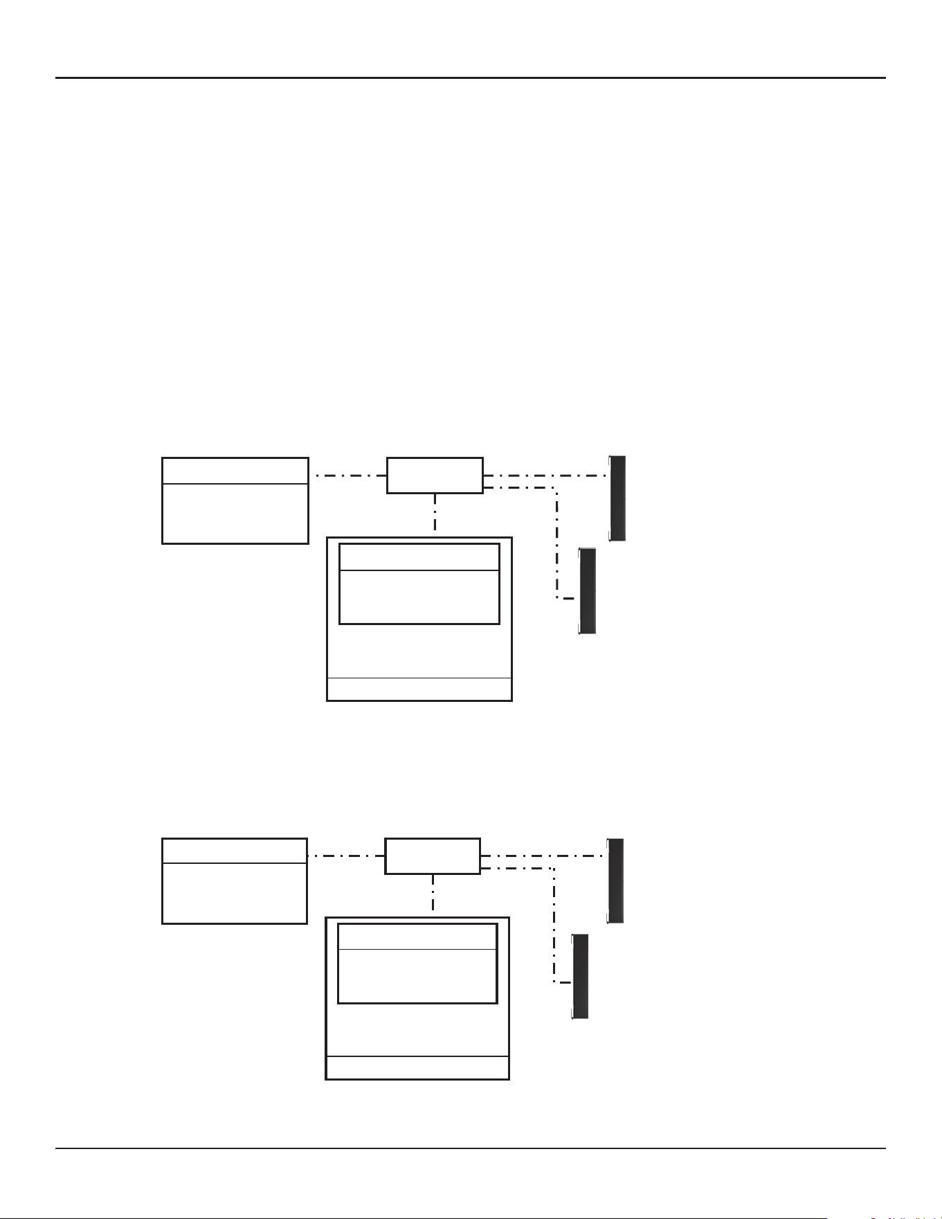
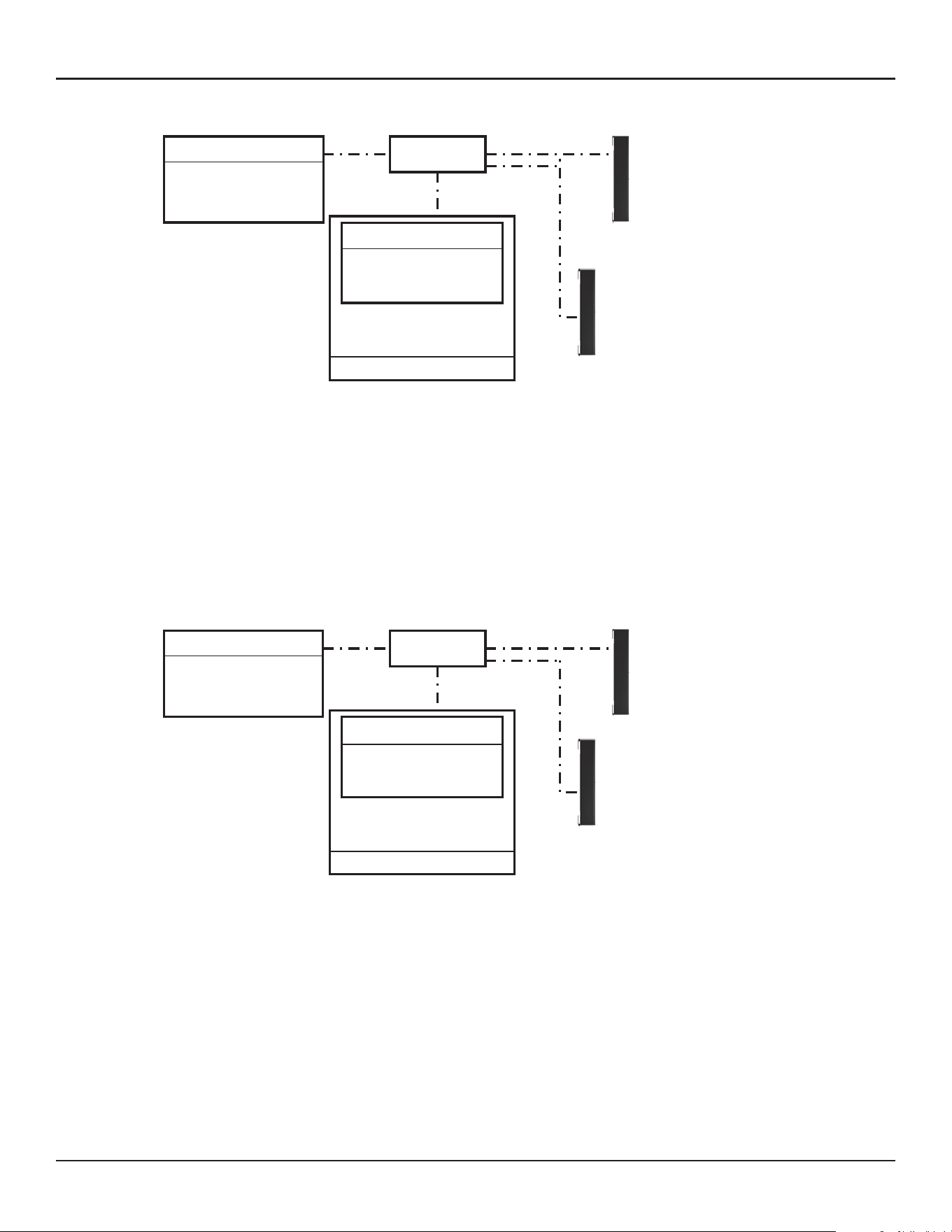
48 - Design Guide Design Guide - 49
Appendix: How to Set Up IP AddressAppendix: How to Set Up IP Address
5. Change IP of PC to 192.168.0.10, Subnet mask 255.255.255.0.
6. Launch CSD. Now BMW arrays appear in the Project View.
a. If not, go to System > Enable Dante Control.
b. If MA12X arrays still do not appear, make sure the right Network Interface Card (NIC) is selected for
CSD. You can see the current NIC from the top menu: System > Host NIC Setup.
7. Scan ControlSpace Network. Now ESP with Dante Card appears.
a. If not, make sure the Project Network Address is 192.168.0.xxx. You can set this by selecting Tools > Set
Project Network Properties.
b. By default, the IP of ESP is 192.168.0.160.
8. Set the IP setting of ESP from DHCP enabled to static.
Switch
MSA12X
MSA12X
Dante Card
ESP
PC
Static
IP: 192.168.0.10
Subnet: 255.255.255.0
Static
IP: 192.168.0.101
Subnet: 255.255.255.0
DHCP
IP: 192.168.0.160
Subnet: 255.255.255.0
Static
IP: 192.168.0.102
Subnet: 255.255.255.0
IP: 192.168.0.103
Subnet: 255.255.255.0
Static
Switch
MSA12X
MSA12X
Dante Card
ESP
PC
Static
IP: 192.168.0.10
Subnet: 255.255.255.0
Static
IP: 192.168.0.101
Subnet: 255.255.255.0
Static
IP: 192.168.0.160
Subnet: 255.255.255.0
Static
IP: 192.168.0.102
Subnet: 255.255.255.0
IP: 192.168.0.103
Subnet: 255.255.255.0
Static
With 1U ESP without Dante® Card, Analog Input to MSA12X, No Router
1. Connect PC and all the devices to the network.
2. Set IP of PC to DHCP.
3. Launch Dante Controller.
a. Make sure all the Dante Devices (incl. MSA12X arrays) appear.
b. At this point, all the Dante Devices should be
i. IP: 169.254.xxx.xxx
ii. Subnet Mask: 255.255.0.0
4. Change IP of all the Dante devices to static:
i. IP: 192.168.0.xxx (e.g. 101, 102, …)
ii. Subnet Mask: 255.255.255.0
Each time you change the IP, that Dante device may disappear in the Dante Controller, or even if it can be
seen, you may not be able to assign Dante subscriptions. This is OK.
Switch
MSA12X
MSA12X
ESP (no Dante Card)
PC
DHCP
IP: 169.254.xxx.xxx
Subnet: 255.255.0.0
DHCP
IP: 169.254.xxx.xxx
Subnet: 255.255.0.0
DHCP
IP: 192.168.0.160
Subnet: 255.255.255.0
Analog input for MSA12X (Audio Signal)
DHCP
IP: 169.254.xxx.xxx
Subnet: 255.255.0.0
Switch
MSA12X
MSA12X
PC
DHCP
IP: 169.254.xxx.xxx
Subnet: 255.255.0.0
Static
IP: 192.168.0.101
Subnet: 255.255.255.0
IP: 192.168.0.102
Subnet: 255.255.255.0
Static
Last 3 digits of IP (bold)
are just examples
ESP (no Dante Card)
DHCP
IP: 192.168.0.160
Subnet: 255.255.255.0
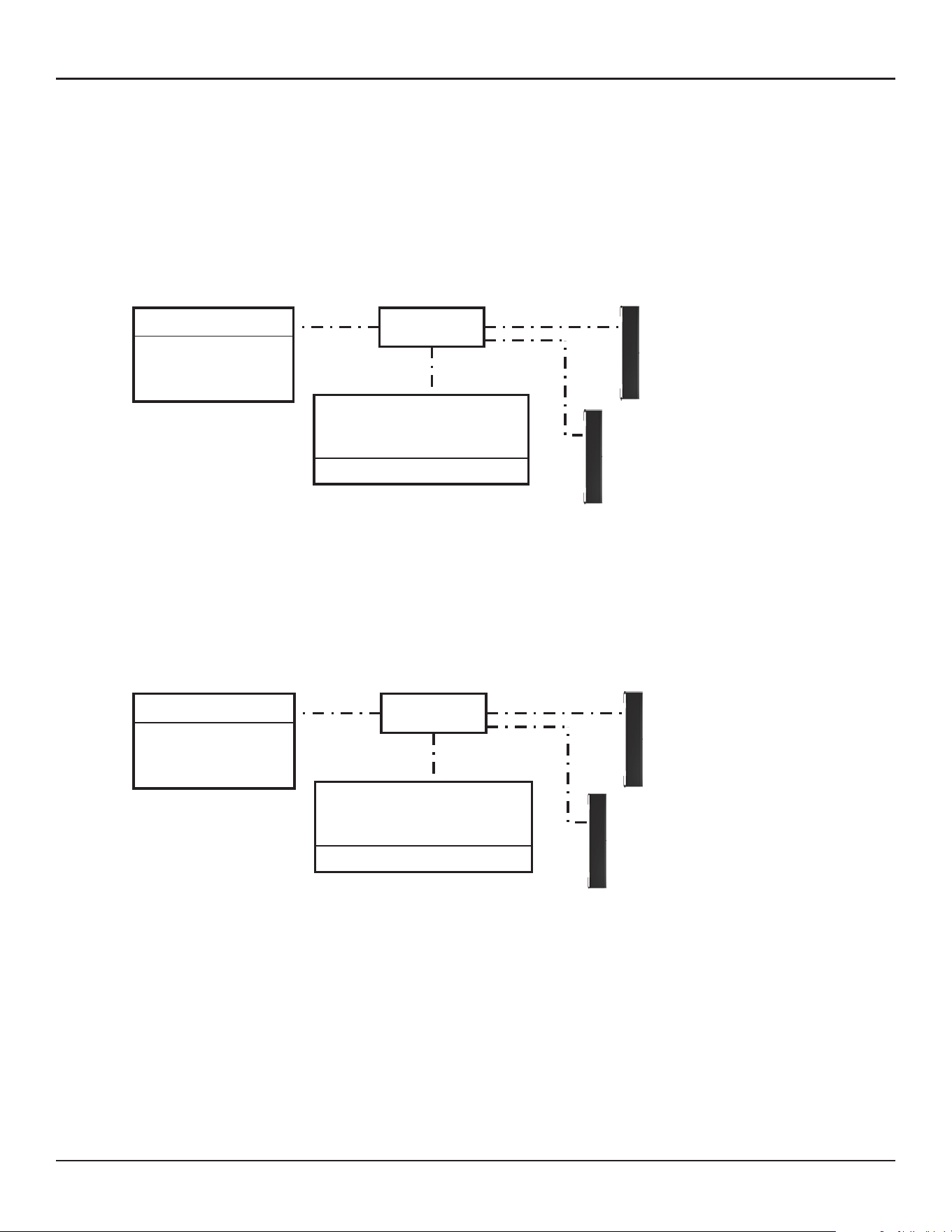
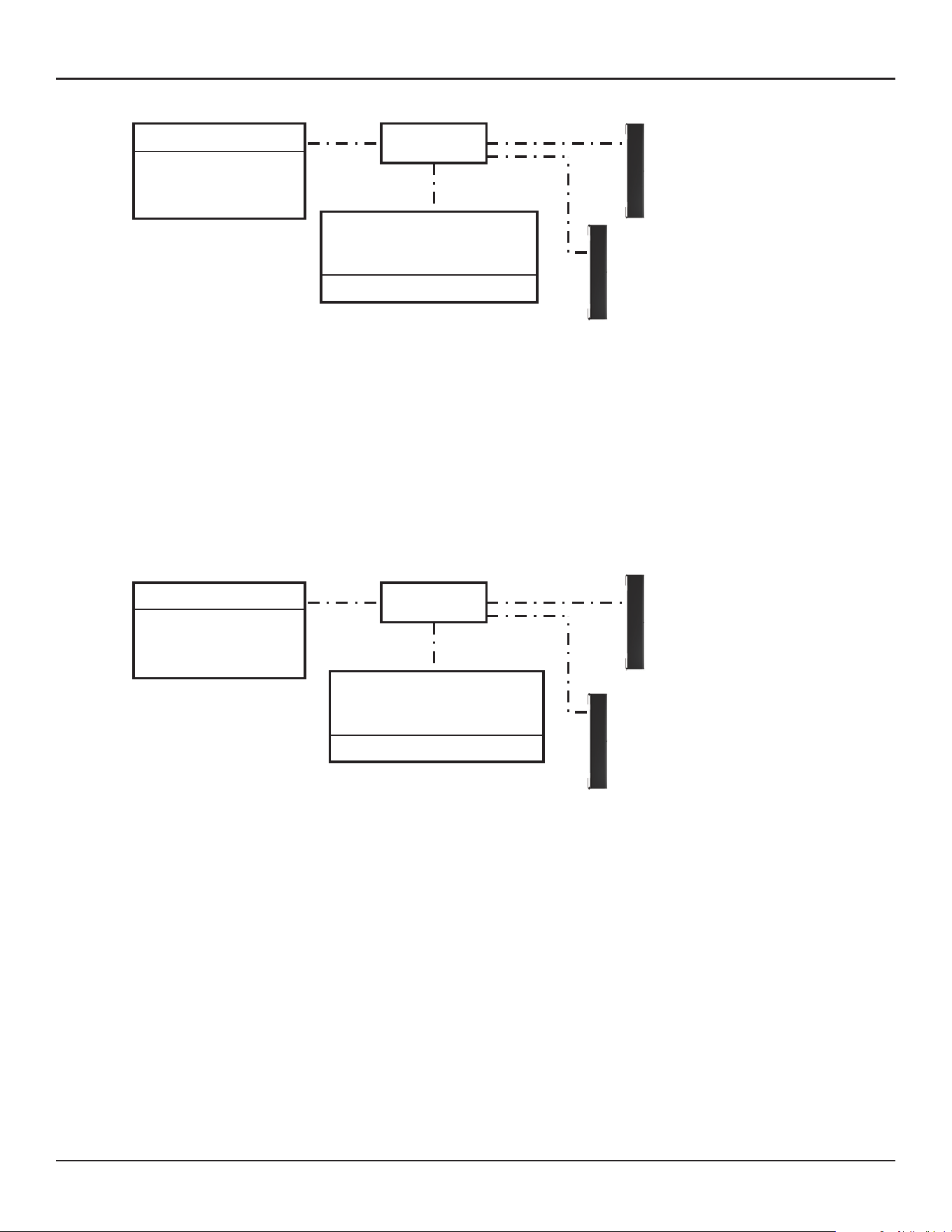
50 - Design Guide Design Guide - 51
Appendix: How to Set Up IP AddressAppendix: How to Set Up IP Address
5. Change IP of PC to 192.168.0.10, Subnet mask 255:255:255.0.
6. Launch CSD. Now MSA12X arrays appear in the Project View.
a. If not, go to System > Enable Dante Control.
b. If MA12X arrays still do not appear, make sure the right Network Interface Card (NIC) is selected for
CSD. You can see the current NIC from the top menu: System > Host NIC Setup.
7. Scan ControlSpace Network. Now ESP appears.
a. If not, make sure the Project Network Address is 192.168.0.xxx. You can set this by selecting Tools > Set
Project Network Properties.
b. By default the IP of ESP is 192.168.0.160.
8. Set the IP setting of ESP from DHCP enabled to static.
9. Make sure to change the input type of each MSA12X device to Analog.
Note: Dual beam option cannot be used when the input is Analog. Without a Dante Card, you cannot change
the beam pattern by invoking a beam preset via Parameter-set.
Switch
MSA12X
MSA12X
PC
Static
IP: 192.168.0.10
Subnet: 255.255.255.0
Static
IP: 192.168.0.101
Subnet: 255.255.255.0
IP: 192.168.0.102
Subnet: 255.255.255.0
Static
ESP (no Dante Card)
Static
IP: 192.168.0.160
Subnet: 255.255.255.0
Switch
MSA12X
MSA12X
PC
Static
IP: 192.168.0.10
Subnet: 255.255.255.0
Static
IP: 192.168.0.101
Subnet: 255.255.255.0
IP: 192.168.0.102
Subnet: 255.255.255.0
Static
ESP (no Dante Card)
DHCP
IP: 192.168.0.160
Subnet: 255.255.255.0
Without ESP/EX-1280C, Analog Input to MSA12X, No Router
MSA12X is a Dante device. Even if you do not use Dante connection for sending audio signal, the beam
configuration setup is performed through Dante Network, and you have to setup IP of PC and MSA12X.
1. Connect PC and all the devices to the network.
2. Set IP of PC to DHCP. At this point, you may not be able to see MSA12X in CSD, since Project Network
Address is still 192.168.0.xxx.
3. Launch Dante Controller.
a. Make sure all the Dante Devices (incl. MSA12X arrays) appear.
b. At this point, all the Dante Devices should be
i. IP: 169.254.xxx.xxx
ii. Subnet Mask: 255.255.0.0
4. Change IP of all the Dante devices to static:
i. IP: 192.168.0.xxx (e.g. 101, 102, …)
ii. Subnet Mask: 255.255.255.0
Each time you change the IP, that Dante device may disappear in the Dante Controller, or even if it can be
seen, you may not be able to assign Dante subscriptions. This is OK.
Switch
MSA12X
MSA12X
DHCP
IP: 169.254.xxx.xxx
Subnet: 255.255.0.0
DHCP
IP: 169.254.xxx.xxx
Subnet: 255.255.0.0
Analog input for MSA12X (Audio Signal)
DHCP
IP: 169.254.xxx.xxx
Subnet: 255.255.0.0
Project Network Address of CSD
192.168.0.xxx by default
PC
Switch
MSA12X
MSA12X
PC
DHCP
IP: 169.254.xxx.xxx
Subnet: 255.255.0.0
Static
IP: 192.168.0.101
Subnet: 255.255.255.0
IP: 192.168.0.102
Subnet: 255.255.255.0
Static
Last 3 digits of IP (bold)
are just examples
Project Network Address of CSD
192.168.0.xxx by default
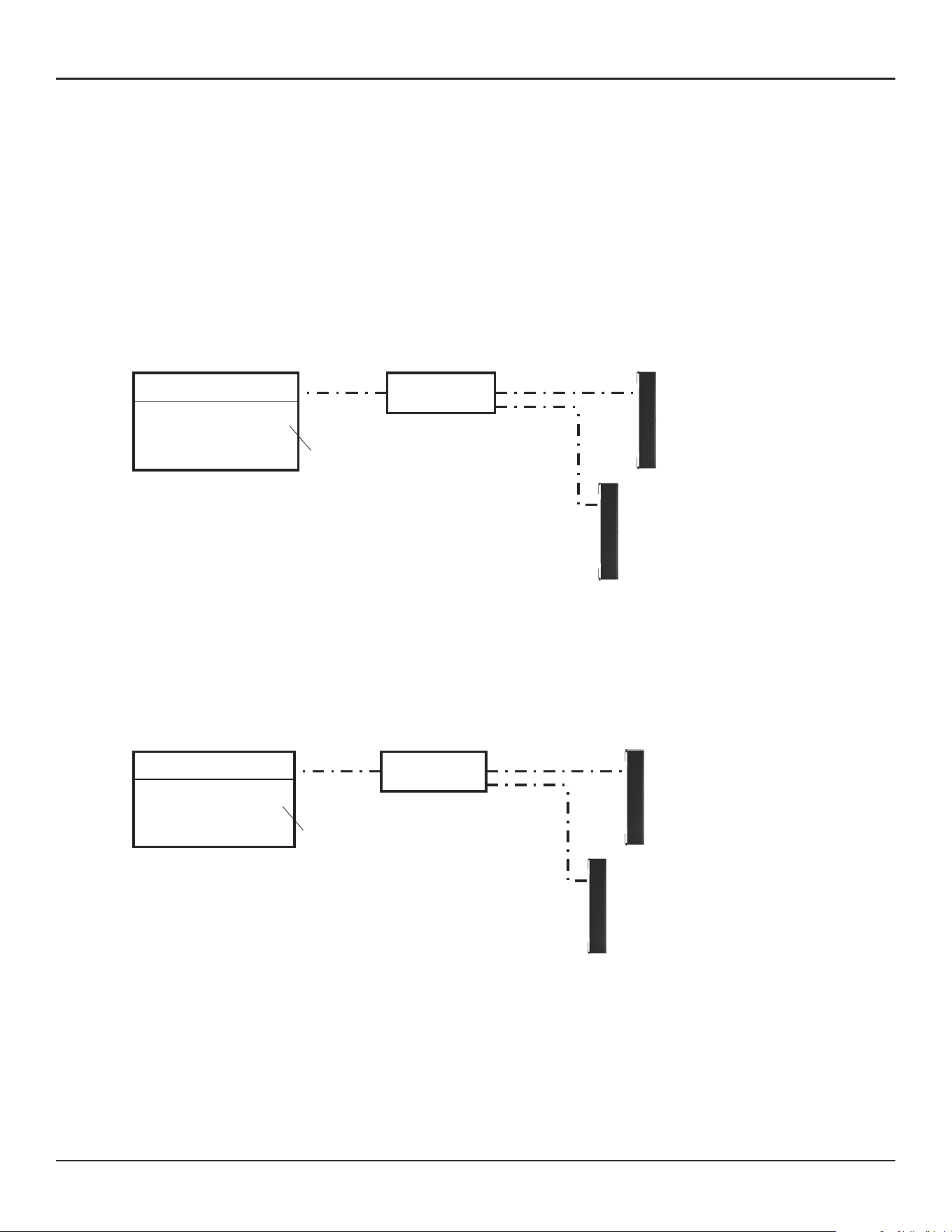
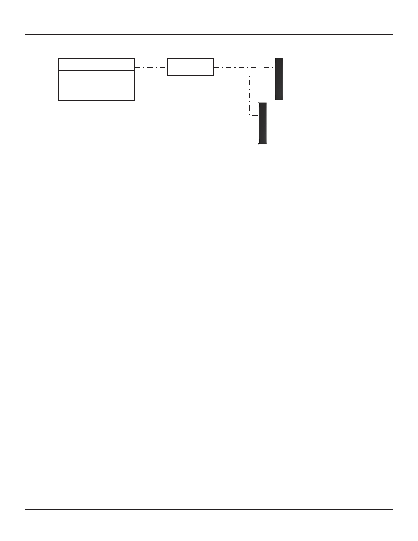
52 - Design Guide
Appendix: How to Set Up IP Address
5. Change IP of PC to 192.168.0.10, Subnet mask 255:255:255.0.
6. Launch CSD. Now MSA12X arrays appear in the Project View.
a. If not, make sure the Project Network Address is 192.168.0.xxx. You can set this by selecting Tools > Set
Project Network Properties.
b. By default, the IP of ESP is 192.168.0.160.
7. You can set up the beam properties of MSA12X without ‘Go Online…” in CSD, as long as the Dante Control
and Endpoint Control are enabled.
8. Make sure to change the input type of each MSA12X device to Analog.
If you do not have a network switch in the system, connect your PC to each MSA12X directly, and repeat the
above process for each array.
Note: You cannot change the beam pattern via a beam preset without a 1U ESP (ESP-880/1240/4120/1600)
with Dante Card, or ControlSpace EX-1280C in the system.
Switch
MSA12X
MSA12X
PC
Static
IP: 192.168.0.10
Subnet: 255.255.255.0
Static
IP: 192.168.0.101
Subnet: 255.255.255.0
IP: 192.168.0.102
Subnet: 255.255.255.0
Static

© 2019 Bose Corporation, All rights reserved.
Dante® is a registered trademark of Audinate Pty Ltd.
All trademarks are the property of their respective owners.
Information subject to change.
03/2019
PRO.BOSE.COM
