Loading ...
Loading ...
Loading ...

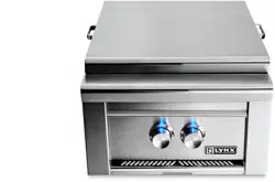
L.P. hose/regulator
3/8”
flare fitting
(hose ships
pre-installed
on grill)
20 lb. Type 1 L.P. tank
L.P. GAS
Grills oriced for use with L.P. gas
come equipped with an LP hose/
regulator assembly for connec-
tion to a standard 20 lb. L.P. cyl-
inder (Type 1). All ttings neces-
sary to attach the hose/regulator
to the grill are included. The L.P.
tank is not included. Operating
pressure: 10.0”W.C.
L.P. Tank Requirements
A dented or rusty L.P. tank may
be hazardous and should be
checked by your L.P. supplier.
Never use a cylinder with a dam-
aged valve. Always check for
leaks after every L.P. tank change
(see page 11).
The L.P. gas cylinder must be
constructed and marked in ac-
cordance with the specications
for L.P. gas cylinders of the U.S.
Department of Transportation
(DOT) and designed for use with
a Type 1 system only. Do not
change the regulator/hose as-
sembly from that supplied with
the unit or attempt to use a
5LP-A equipped regulator/hose
assembly with a standard 510
POL tank/valve assembly. The
cylinder must be provided with
a shut o valve terminating in
an L.P. gas supply cylinder valve
outlet specied, as applicable,
for connection Type 1.
Cylinders must be stored
outdoors in a well-ventilat-
ed area out of the reach of
children. If the appliance
is stored indoors, the L.P.
cylinder must be removed
from the appliance, and
stored outside.
Turn o LP-gas supply at cylinder
when appliance is not in use.
Fermez l’alimentation en GPL à
la bouteille si l’appareil ne fonc-
tionne pas.
The LP-gas supply cylinder must
be disconnected when this ap-
pliance is not in use.
La bouteille de GPL doit être dé-
connectée si cet appareil ne fonc-
tionne pas.
Your local L.P. lling station
should be equipped with the
proper equipment to ll your
tank. If trading your tank in,
always ensure to obtain only
Type 1 20lb cylinders with an
overll protection device.
L.P. Connections
Connect the 3/8” are end of the
L.P. hose to the brass adapter on
the manifold (as shown in g-
ure 9-1). Connect the Regulator
to the tank (with the tank valve
fully closed). Although the ow
of gas is stopped when the Type
1 system is disconnected, you
should always turn the L.P. tank
main valve o after each use
and during transport of the tank
or unit. Insert the regulator inlet
into the tank valve and turn the
black coupler clockwise until the
coupler is tight. Do not over-
tighten the coupler.
To disconnect the coupler, rst
make sure the main tank valve
is turned o. Grasp the coupler
and turn counter clockwise. The
inlet will then disengage.
Gas Line Purging
To purge the L.P. gas line, make
sure all controls are in the OFF
position. Turn the main tank
valve on SLOWLY and turn one
burner control valve on the unit
to the “light” position (DO NOT
LITE GRILL). Leave control ON for
about 20 seconds to allow the
air in the system to purge. Wait
5 minutes before attempting to
light the burners.
Do not attempt lighting the grill
within 5 minutes after purging!
Figure 9-1
- Typical attachment to L.P. tank.
9
Loading ...
Loading ...
Loading ...