User manual Thermostat
Before You Begin
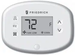
Friedrich EMRT2 Energy Management Thermostats for the hospitality industry deliver unprecedented energy savings without compromising guest comfort.
An integrated occupancy sensor uses a combination of motion and thermal sensing technologies for accurate occupancy detection. Reliable occupancy detection allows for energy savings when rooms are unoccupied.
Energy-saving presets eliminate the guesswork and make it easy to adjust the energy-saving settings. (Patent Pending)
Fully configurable energy-saving settings allow for customization of the thermostat energy-saving settings to fit any situation.
Comprehensive configuration options ensure full compatibility with virtually any existing or emerging hospitality HVAC system with up to 2 heat and 1 cool stages.
Built-in wireless mesh-networking enables optional online management.
For installation of a networking thermostat with online management, refer to the “Network Installation” manual.
- Determine the appropriate installation location for the thermostat. The thermostat should face the bed area of the room.
- Set the PTAC/Vert-I-Pak unit to “External Thermostat” (Class 2) mode. Consult the PTAC/Vert-I-Pak unit documentation to determine how to set the PTAC/Vert-I-Pak unit to “External Thermostat” mode.
Programming a Thermostat with a Network Programmer.
In case of Network Installation with Online management, the thermostat must be programmed with a Network Programmer specific to the property before the installation.
The thermostat must not be powered during the pairing procedure.
- Plug one programmer connector into the thermostat;
- Push the black button on the programmer. The red light on the programmer should turn on and remain steadily lit;
If the red light on the programmer is blinking or is not steadily lit, unplug the programmer from the thermostat and repeat the steps above.
- Unplug the programmer from the thermostat;
Thermostat Installation
- Set the PTAC unit to “External Thermostat” (Class 2) mode.
Mounting the thermostat to the wall
- Unplug the PTAC/Vert-I-Pak unit;
- Remove the thermostat cover;
- Connect the thermostat wires to the supplied Wiring Connector - refer to the Wiring Table to determine proper connections;
- Plug in the wiring connector into to the thermostat;
- Use the supplied wall anchors and mounting screws to secure the thermostat to the wall;
- Follow the “Thermostat Configuration” instructions;
- Replace the thermostat cover and screw in the locking screw;
- Plug in the PTAC/Vert-I-Pak unit.
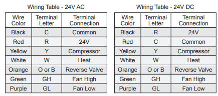
NOTE: If the PTAC/Vert-I-Pak unit has only one (1) fan speed, connect both fan control wires – Green and Purple – to the fan terminal (G).
Thermostat Configuration
Once the thermostat is powered, thermostat configuration settings will appear on the thermostat screen.
In order to properly operate the PTAC/Vert-I-Pak unit:
- Set the thermostat clock;
- Enter the room number;
- Configure the equipment settings;
- Select Energy Savings Preset;
The thermostat configuration screens have a 3-minute time-out. If no action is taken within three (3) minutes, the thermostat will exit configuration settings.
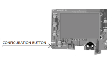
NOTE: You can access Thermostat Configuration settings at any time by pressing the “Configuration” button.
Setting the thermostat clock
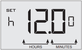
Set the thermostat clock to current time in 24h (Military Time) format.
- Use the “Up” and “Down” buttons to set the hours;
- Press the “Fan” button to advance to the minutes setting;
- Use the “Up” an “Down” buttons to set the minutes;
- Press the “F/C” button to advance to the next menu;
Setting the clock correctly is crucial for proper operation of the thermostat.
Entering the room number
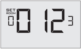
Enter the room number by changing the digits on the screen. Leading zeros “0” preceding other digits will be ignored, i.e. Room number “123” should be entered as “00123”.
- Use the “Up” and “Down” buttons to change the digit;
- Press the “Fan” button advance to the next digit;
- Press the “F/C” button to advance to the next menu;
Entering the room number correctly is crucial for proper operation of remotely managed thermostats.
Configuring the Equipment Settings - Compressor Type
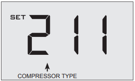
- Use the “Up” and “Down” buttons to change the compressor type by changing the fi rst digit;
0 No Compressor
1 Heat Pump
2 * Air Conditioner
- Press the “Fan” button to advance to the next setting;
* Indicates default setting;
Configuring the Equipment Settings - Electric Heat
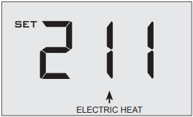
- Use the “Up” and “Down” buttons to change the Electric Heat setting by changing the second digit;
0 No Electric Heat
1 * Electric Heat
- Press the “Fan” button to advance to the next setting;
* Indicates default setting;
Configuring the Equipment Settings - Reversing Valve
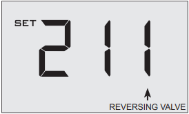
- Use the “Up” and “Down” buttons to change the Reversing Valve setting by changing the third digit;
0 OB contact is energized to cool;
1 * OB contact is energized to heat;
Refer to the PTAC unit documentation to determine the correct OB VALVE setting.
If incorrect OB VALVE Setting is selected, the PTAC unit will turn on the heating when air conditioning is requested and turn on the air conditioning when heating is requested;
- Press the “Fan” button to advance to the next setting;
- Press the “F/C” button to advance to the next menu;
* Indicates default setting;
Configuring the Energy Saving Settings
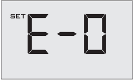
- Use the “Up” and “Down” buttons to select the Energy Saving preset:
E-0* Energy Savings Off - No Temperature Setback;
E-1 Lowest Energy Savings;
E-2 Lower Energy Savings;
E-3 Standard Energy Savings;
E-4 Higher Energy Savings;
E-5 Highest Energy Savings;
Refer to the APPENDIX 1 for Energy Saving Preset details.
E-C Indicates “Custom Energy Savings Settings” in case the active thermostat savings settings differ from any Energy Saving preset;
For details, refer to the “Custom Energy Savings Settings” section;
- Press the “Power” button to save the Thermostat Configuration and start using the thermostat;
* Indicates default setting;
Testing the thermostat
Following the thermostat configuration, test if the thermostat is controlling the PTAC unit.
- Press the “Power” button to turn the thermostat ON;
- Press the “Up” and “Down” buttons to change the temperature set point above and below the current room temperature to test if the thermostat initiates heating and cooling - the PTAC unit should turn heating and air conditioning on and off.
- Change the fan speed by touching the “Fan” button to test if the thermostat is controlling the fan speed.
Custom Energy Savings Settings
If you don’t want to use the one of the energy saving presets listed on page 17 and detailed in the Appendix 1, you can enter the custom energy savings settings.
Accessing the Thermostat Settings
- Press and hold the “Confi guration” button until the fi rst thermostat settings screen appears.
The thermostat must be turned on to access the thermostat settings.
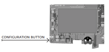
NOTE: You can access Thermostat Confi guration settings at any time by pressing the “Confi guration” button.
Using the Thermostat Settings Screens
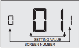
- Use the “Up” and “Down” buttons to change the setting;
- Press the “F/C” button to advance to the next setting;
- Press the “Fan” button to return to the previous setting;
- Press the “Power” button to save and exit thermostat settings;
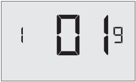
01 – FAN CONTROL MODE
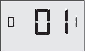
Select Fan Control Mode:
00 MANUAL - guest can select automatic or continuous fan mode;
01 * AUTOMATIC - fan runs only when there is a demand for heating or air conditioning;
* Indicates default setting;
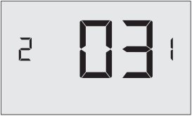
02 – 1ST STAGE DIFFERENTIAL - HEAT
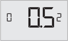
02-30 (0.2°F - 3.0°F; 0.5°F* default setting) Select the number of degrees the thermostat has to sense between the automatic changeover temperature for heat and the room temperature before a call for the 1st stage heating is initiated.
03 – 2ND STAGE DIFFERENTIAL - HEAT
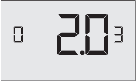
10-20 (1.0°F - 2.0°F*; 2.0°F* default setting) Select the difference between 1st stage heating and 2nd stage heating initiation.
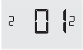
04 – 1ST STAGE DIFFERENTIAL - COOL
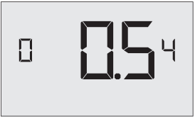
02-30 (0.2°F - 3.0°F; 0.5°F* default setting) Select the number of degrees the thermostat has to sense between the automatic changeover temperature for cool and the room temperature before a call for the 1st stage cooling is initiated.
05 – INCIDENTAL OCCUPANCY THRESHOLD
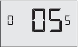
00-60 (05* default setting) Select the minimum period of time (in minutes) for which occupancy needs to be detected to enter the guest occupancy mode.
When occupancy is detected, thermostat will switch to occupied mode for a duration of “Incidental Occupancy Threshold” selected here.
If occupancy is detected for a period of time shorter than the “Incidental Occupancy Threshold” selected here, the thermostat will automatically revert to unoccupied mode at the end of the “Incidental Occupancy Threshold” period and continue to observe energy saving functions that were in effect before the room became occupied. This setting allows ignoring incidental room visits.
If occupancy is detected for a period of time longer than the “Incidental Occupancy Threshold” selected here, the thermostat will enter the guest occupancy mode. When the thermostat is in the guest occupancy mode, it will revert to unoccupied mode and initiate the setback temperature only when occupancy is not detected for the duration of the setback delay (Heat or Cool) period.
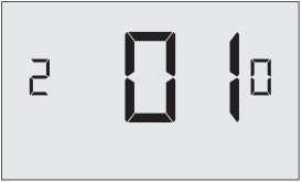
06 – NIGHT OCCUPANCY THRESHOLD
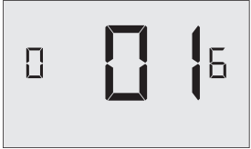
00-60 (01* default setting) Select the minimum period of time (in minutes) for which occupancy needs to be detected in order to consider the room occupied during the “Night Occupancy”period.
When occupancy is detected during the “Night Occupancy Period” for longer than the “Night Occupancy Threshold” selected here, the thermostat will instantaneously switch to occupied mode.
If occupancy is detected for a period of time shorter than the “Night Occupancy Threshold” selected here, the thermostat will automatically revert to unoccupied mode and continue to observe energy saving functions that were in effect before the room became occupied.
If occupancy is detected for a period of time longer than the “Night Occupancy Threshold” selected here, the thermostat will disable the occupancy sensor and consider the room occupied until the end of the “Night Occupancy” period.
This feature ensures that energy saving functions that may affect guest comfort will not come in effect during the “Night Occupancy” period.
07 – FORCED 2ND STAGE HEATING
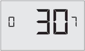
00-60 (30* default setting) Select a number of minutes 1st stage heating will run before 2nd stage heating is automatically initiated if the guest set point is not reached and the 2nd stage heating is not initiated through differential settings.
This feature allows automatically turning on 2nd stage heating to avoid excessive compressor use.
Set to 00 to disable the feature.
08 – NIGHT OCCUPANCY START
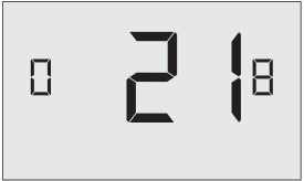
00-23 (21* default setting) Select the start time (in hours - 24- hour clock) for “Night Occupancy”
If occupancy is detected for a period of time longer than the “Night Occupancy Threshold” during “Night Occupancy” period, the thermostat will disable the occupancy sensor and consider the room occupied until the end of the “Night Occupancy” period.
This feature ensures that energy saving functions that may affect guest comfort will not come in effect during the “Night Occupancy” period if room was occupied for a period of time longer than “Night Occupancy Threshold”.
09 – NIGHT OCCUPANCY END
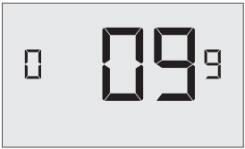
00-23 (09* default setting) Select the time (in hours - 24-hour clock) for “Night Occupancy” to end.
The time of day the “Night Occupancy” ends and the thermostat switches back to the room sensing settings chosen in the other occupancy modes.
10 – TEMPERATURE RECOVERY TIME
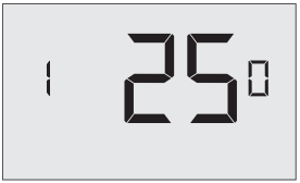
00-60 (25* default setting) Select the maximum time allowed for a PTAC unit to attain temperature as defi ned by Heat and Cool “Recovery Temperature”;
“Temperature Recovery Time” selected here and the actual temperature recovery ability of the PTAC unit are used to calculate setback temperatures. Calculated setback temperatures maximize energy savings and at the same time ensure that a comfortable room temperature (defi ned as Heat and Cool “Recovery Temperature”) will be restored within the selected “Temperature Recovery Time”.
Setting the “Temperature Recovery Time” to “00”, disables temperature recovery. When temperature recovery is disabled, thermostat will use the Minimum and Maximum Setback Temperatures as setback set points.
11 – RECOVERY TEMPERATURE - HEAT
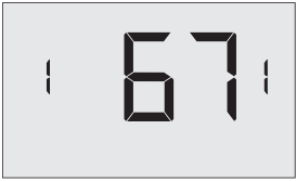
62-82 (67°F* default setting) Select the room temperature in °F that a PTAC unit will have to attain within the selected “Temperature Recovery Time” when there is a need for heating.
12 – TEMPERATURE SETBACK DELAY - HEAT
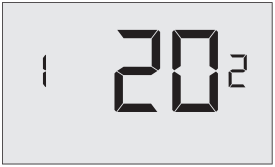
00-120 (20* default setting) Select the time delay (in minutes) for which the room that is in the guest occupancy mode needs to be unoccupied before the temperature setback is initiated.
This feature prevents initiating temperature setback prematurely while the guest is still in the room but in an area where occupancy cannot be detected by the occupancy sensor.
Setting the “Temperature Setback Delay - Heat” to “00”, disables the setback in the heat mode. Set to “00” to disable EMS.
13 – MINIMUM SETBACK TEMPERATURE
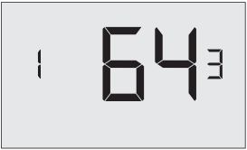
52-72 (64°F* default setting) Select the “Minimum Setback Temperature” in °F.
Setback temperature is calculated by measuring PTAC unit’s ability to attain “Recovery Temperature - Heat” within “Temperature Recovery Time”.
If recovery is disabled (“Temperature Recovery Time” is set to “0”) or if setback temperatures have not yet been calculated, the “Minimum Setback Temperature” value will be used as the setback temperature for heating.
If calculated setback temperature for heating is lower than “Minimum Setback Temperature”, then the “Minimum Setback Temperature” will be used as setback temperature for heating.
This feature allows defi ning the minimum temperature in a room when room is unoccupied and the thermostat is in the setback mode.
14 – TEMPERATURE SETBACK DELAY - COOL
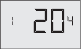
00-120 (20* default setting) Select the time delay (in minutes) for which the room that is in the guest occupancy mode needs to be unoccupied before the temperature setback is initiated.
This feature prevents initiating temperature setback prematurely while the guest is still in the room but in an area where occupancy cannot be detected by the occupancy sensor.
Setting the “Temperature Setback Delay - Cool” to “00”, disables the setback in the cool mode. Set to “00” to disable EMS.
15 – MAXIMUM SETBACK TEMPERATURE
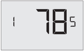
72-92 (78°F* default setting) Select the “Maximum Setback Temperature” in °F.
Setback temperature is calculated by measuring PTAC unit’s ability to attain “Recovery Temperature - Cool” within “Temperature Recovery Time”.
If recovery is disabled (“Temperature Recovery Time” is set to “0”) or if setback temperatures have not yet been calculated, the “Maximum Setback Temperature” value will be used as the setback temperature for cooling.
If calculated setback temperature for air conditioning is higher than “Maximum Setback Temperature”, then the “Maximum Setback Temperature” will be used as setback temperature for air conditioning.
This feature allows defi ning the maximum temperature in a room when room is unoccupied and the thermostat is in the setback mode.
16 – RECOVERY TEMPERATURE - COOL
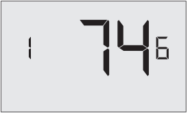
62-82 (74°F* default setting) Select the room temperature in °F that a PTAC unit will have to attain within the selected “Temperature Recovery Time” when there is a need for air conditioning.
17 – MINIMUM SET POINT
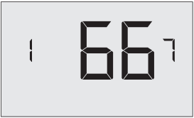
64-84 (66°F* default setting) Select the minimum set point in °F that a guest can select.
18 – MAXIMUM SET POINT
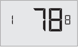
60-82 (78°F* default setting) Select the maximum set point in °F that a guest can select.
19 – TEMPERATURE CONTROL MODE
Select Temperature Control Mode:
00 MANUAL - Allows users to select HEAT only or COOL only temperature control mode to maintain the room temperature;
01 * AUTOMATIC - Thermostat automatically turns on heating or air conditioning to maintain the room temperature at the selected temperature set point;
* Indicates default setting;
20 – AUTO CHANGEOVER SET POINT OFFSET
00-04 (01°F* default setting) Select the difference between the guest-selected set point and the heat and the cool set point when the thermostat is in the automatic temperature control mode.
This value plus the 1st stage differential defi ned in steps 02 and 04, defi nes the temperature at which the thermostat would automatically change heating/cooling modes.
This feature allows adjusting the deadband between the heat and the cool set points in automatic changeover mode in order to avoid the system from bouncing back and forth between heating and cooling under normal operating conditions.
21 – SETBACK SET POINTS / AUTO-RESTORE
00 When room is unoccupied and the thermostat is in the setback mode or turned off, it will NOT maintain the temperature between heat and cool setback set points;
When guest enters the room, the thermostat will be turned off - it will not automatically restore the most recent guest settings;
01 When room is unoccupied and the thermostat is in the setback mode or turned off, it will maintain the temperature between heat and cool setback set points;
When guest enters the room, the thermostat will be turned off - it will not automatically restore the most recent guest settings;
02 When room is unoccupied and the thermostat is in the setback mode or turned off, it will NOT maintain the temperature between heat and cool setback set points;
When guest enters the room, the thermostat will automatically restore the most recent guest settings;
03 * When room is unoccupied and the thermostat is in the setback mode or turned off, it will maintain the temperature between heat and cool setback set points;
When guest enters the room, the thermostat will automatically restore the most recent guest settings.
22 – AUTOMATIC HUMIDITY CONTROL†
00 Disable automatic humidity control;
01 * Enable automatic humidity control;
When “Automatic Humidity Control” is enabled, thermostat will turn on air conditioning in an unoccupied room when humidity raises above 60% and room temperature is above 72°F until either room humidity is below 55% or room temperature is below 72°F;
* Indicates default setting;
† This setting is active only on thermostats with enabled humidity features. Changing this setting on a non-humidity thermostat will have no effect on thermostat operation.
Humidity features can be enabled on compatible thermostats via online management.
Certain models only. Additional fees apply.
23 – TEMPERATURE CALIBRATION
-5.0 – 5.0 (0.0°F* default setting) Calibrate the temperature display : -5.0°F - 5.0°F.
Troubleshooting
Error Codes
ERR 1 Thermostat Temperature Sensor Hardware Defect
ERR 2 Thermostat Radio Hardware Defect
ERR 3 Thermostat Radio Software Defect
ERR 5 Thermostat Memory Defect