INSTALLATION INSTRUCTIONS
69-2065EFS-09
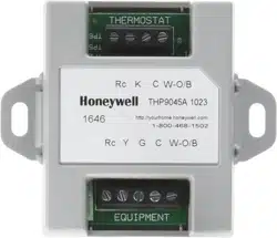
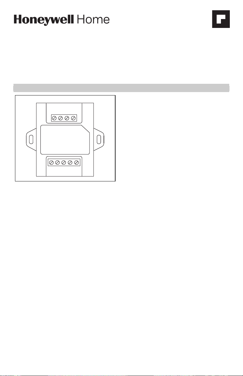
THP9045A1023 Wiring Module
APPLICATION
The THP9045 Wiring Module is designed to be used
with applicable thermostats in which a 24V common
is required and there are not enough wires. The K
terminal on the thermostat can be used to operate
both the fan and compressor on a single wire, and the
module is designed to receive the signal from the K
terminal, split that signal and re-route it to operate
the compressor, and/or fan for normal operation.
Use with the following thermostats:
— THX9321R
— THX9321R5000
— THX9321R1008
— TH8320UP1003
— T5060F7088
FEATURES
• Can be used when a common wire is required.
• Mounts easily on or near HVAC equipment.
INSTALLATION
1. The THP9045 Wiring Module can be equip-
ment- or wall-mounted in any orientation or as
dictated by the surroundings.
2. Precise leveling of the THP9045 module is not
required.
3. Identify the four wires in the wall and connect to
the R, C, W, and K terminals on the thermostat.
4. Wire the K terminal on the thermostat to the K
terminal on the THP9045 module.
5. Wire the R and C terminals on the thermostat to
the R (power) and C (common) terminals on the
THP9045 module and equipment.
6. Wire the W terminal from the thermostat to the
W (heat relay) terminal on the HVAC equipment.
7. Wire the Y and G terminals on the Module to the
Y (Compressor Relay) and G (Fan Relay) termi-
nals on the HVAC equipment.
TERMINALS
R 24V
C 24V Common
YCooling relay
GFan relay
KCommunication
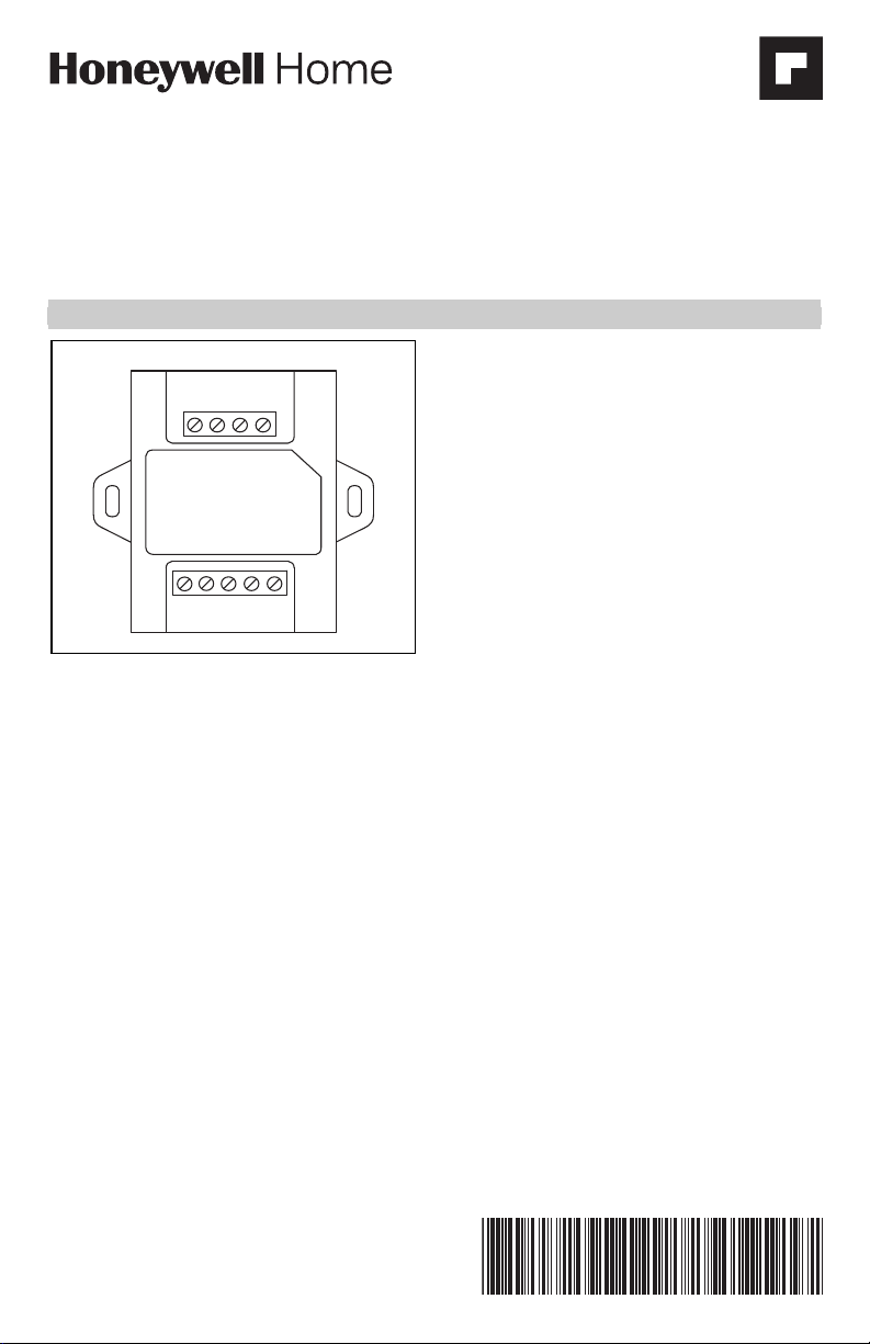
WIRESAVER
W-O/B
Rc
KC
W-O/B
Rc
YG C
THP9045A
EQUIPMENT
THERMOSTAT
M31301B
THP9045A1023 WIRING MODULE
69-2065EFS—09 2
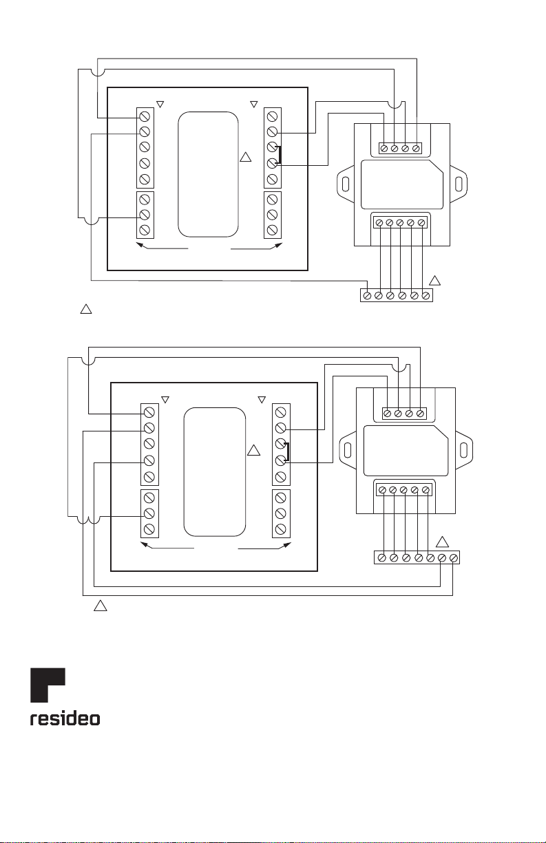
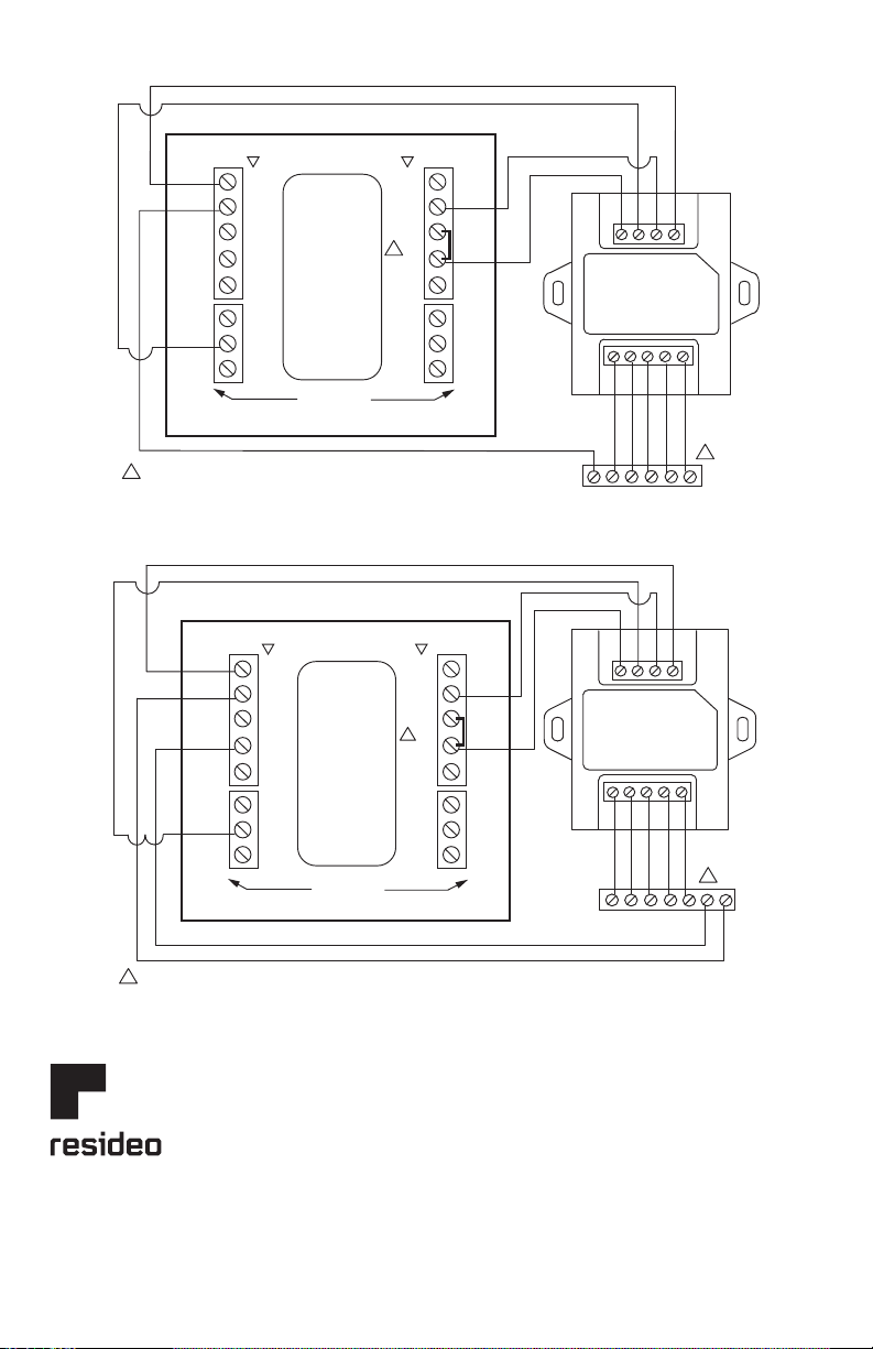
Fig. 1. Example wiring diagram for 1H/1C conventional application.
Fig. 2. Example wiring diagram for a 2H/1C conventional application.
THX9321R SUBBASE
G
C
RY
FURNACE
W
W-O/B
Rc
YG C
THP9045A
WIRESAVER
M31302B
O/B
AUX/E
Y
Y2
G
L
NOT
USED
K
U2
U2
U1
U1
C
Rc
R
NOT
USED
W
W2
Y
Y2
G
NOT
USED
NOT
USED
C
Rc
R
U2
U2
U1
U1
K
NOT
USED
HEAT PUMP
CONVENTIONAL
W-O/B
Rc
KC
THX9321R SUBBASE
G
C
W
RY
W2
M31305BFURNACE
W-O/B
Rc
YG C
WIRESAVER
O/B
W
AUX/E W2
YY
Y2 Y2
GG
L
NOT
USED
NOT
USED
NOT
USED
K
C
Rc
R
U2 U2
U2 U2
U1 U1
U1 U1
K
C
Rc
R
NOT
USED
NOT
USED
HEAT PUMP
CONVENTIONAL
THP9045A
W-O/B
Rc
KC
THP9045A1023 WIRING MODULE
3 69-2065EFS—09
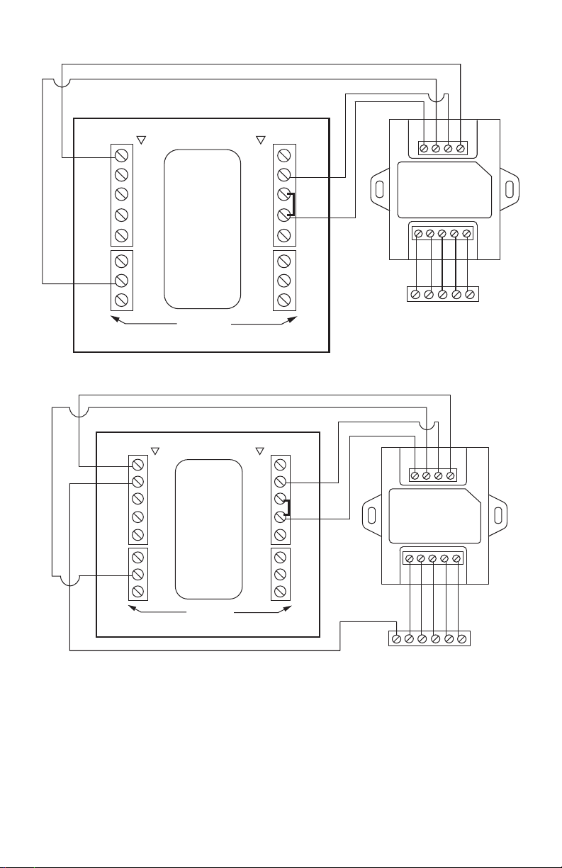
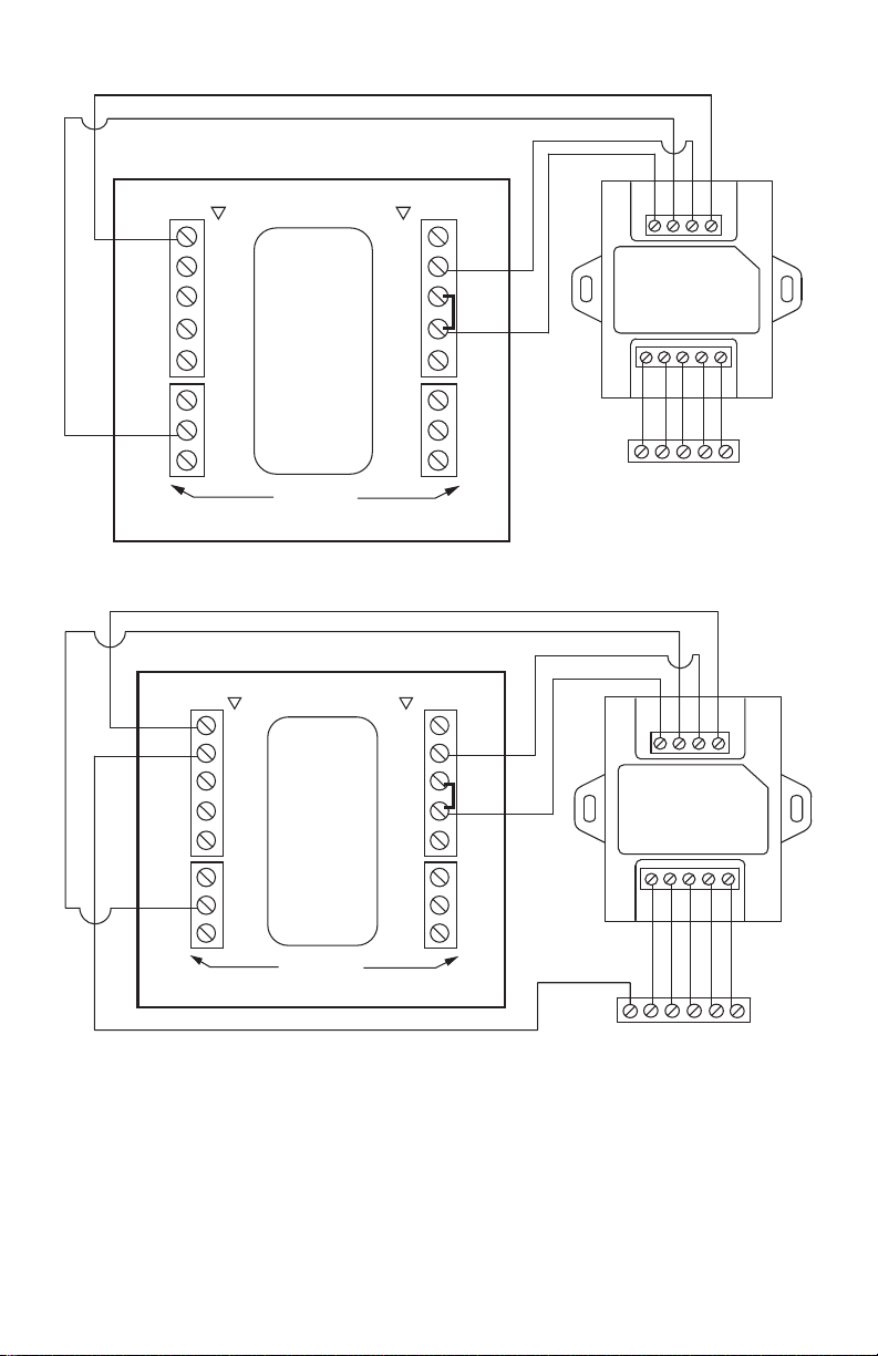
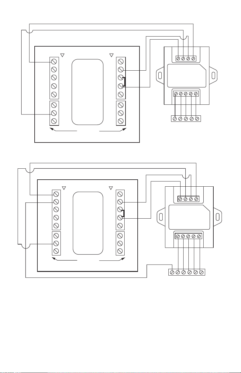
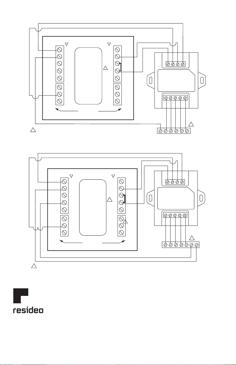
Fig. 3. Example wiring diagram for a 2H/2C conventional application.
Fig. 4. Example wiring diagram for a 1H/1C system with 2 transformers.
THX9321R SUBBASE
G
C
O
RY
AIR HANDLER
Y2 W2
W-O/B
Rc
YG C
WIRESAVER
M31306B
O/B
W
AUX/E
W2
YY
Y2
Y2
GG
L
NOT
USED
NOT
USED
NOT
USED
K
C
Rc
R
U2 U2
U2 U2
U1 U1
U1 U1
K
C
Rc
R
NOT
USED
NOT
USED
HEAT PUMP
CONVENTIONAL
THP9045A
W-O/B
Rc
KC
G
C
RY
HEATER
RW
AIR HANDLER
WIRESAVER
THX9321R SUBBASE
W-O/B
Rc
YG C
M31300B
THP9045A
O/B
W
AUX/E
W2
YY
Y2 Y2
GG
L
NOT
USED
NOT
USED
NOT
USED
K
C
Rc
R
U2 U2
U2 U2
U1 U1
U1 U1
K
C
Rc
R
NOT
USED
NOT
USED
HEAT PUMP
CONVENTIONAL
W-O/B
Rc
KC
REMOVE R/Rc JUMPER
1
1
THP9045A1023 WIRING MODULE
© 2020 Resideo Technologies, Inc. All rights reserved.
The Honeywell Home trademark is used under license from Honeywell International, Inc. This product is manufactured by Resideo Technologies, Inc. and its affiliates.
Tous droits réservés. La marque de commerce Honeywell Home est utilisée avec l’autorisation d’Honeywell International, Inc.
Ce produit est fabriqué par Resideo Technologies, Inc. et ses sociétés affiliées.
Todos los derechos reservados.
La marca comercial Honeywell Home se utiliza bajo licencia de Honeywell International, Inc. Este producto es fabricado por Resideo Technologies, Inc. y sus afiliados.
www.resideo.com
Resideo Technologies, Inc.
1985 Douglas Drive North, Golden Valley, MN 55422
1-800-468-1502
69-2065EFS—09 M.S. Rev. 05-20 | Printed in United States
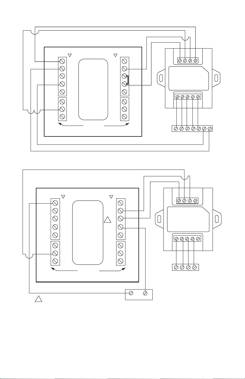
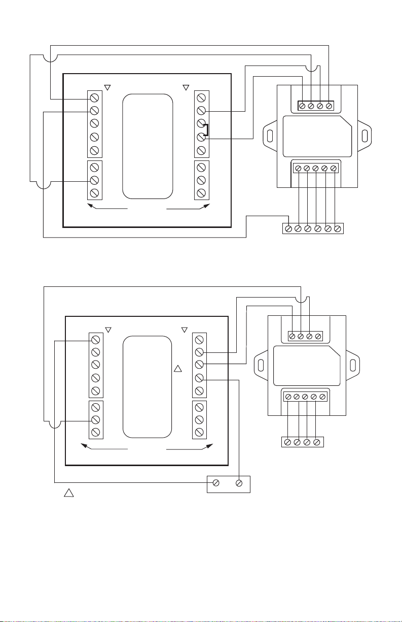
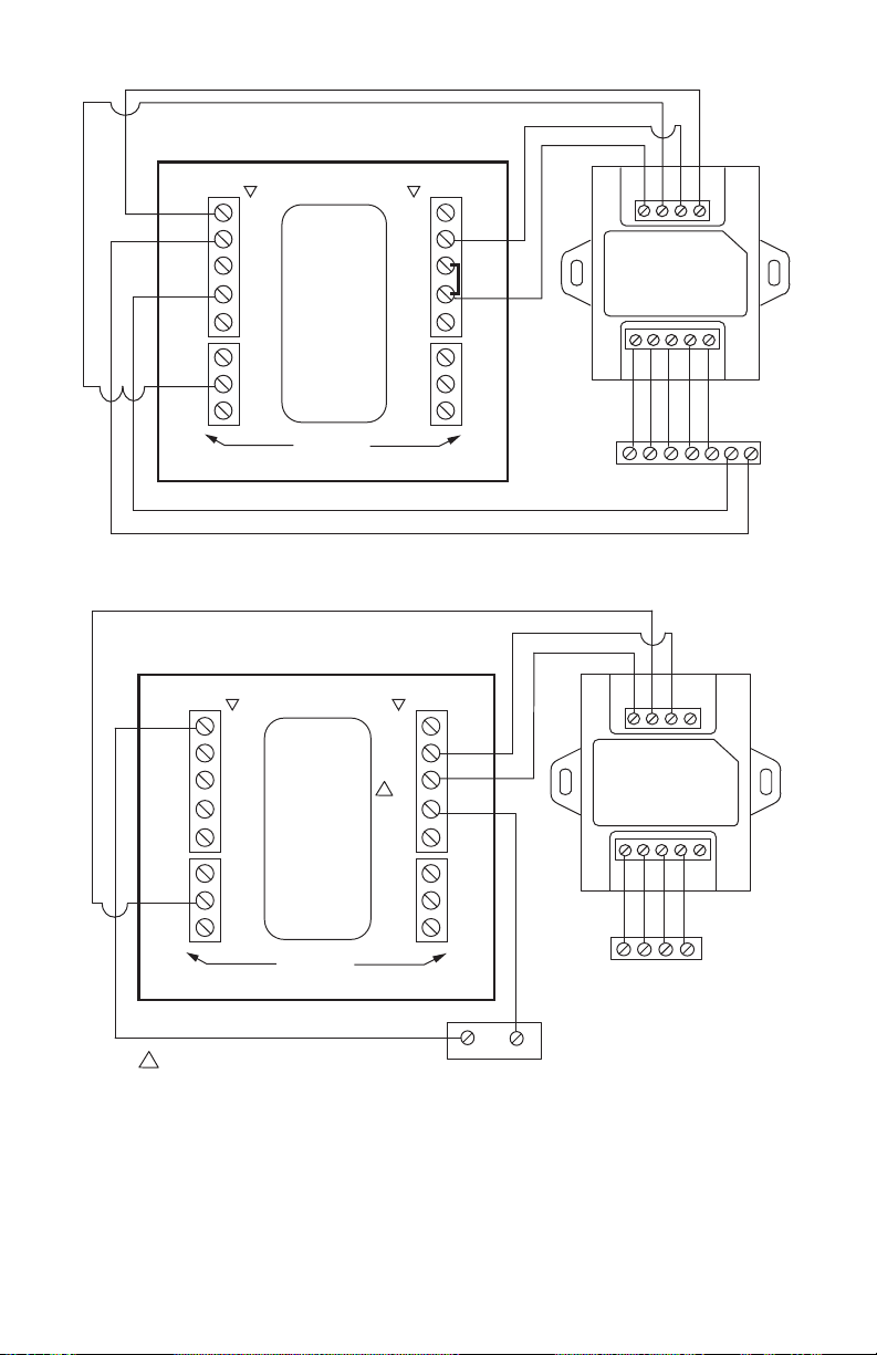
Fig. 5. Example wiring diagram for a 2H/1C heat pump application.
Fig. 6. Example wiring diagram for a 3H/2C heat pump application.
THX9321R SUBBASE
G
C
O
RY
E
MATCH THE WIRES FROM THE HEAT PUMP TO THE AIR HANDLER AS NORMAL.
1
1
AIR HANDLER
W-O/B
Rc
YG C
WIRESAVER
M31303B
O/B
W
AUX/E W2
YY
Y2 Y2
GG
L
NOT
USED
NOT
USED
NOT
USED
K
C
Rc
R
U2 U2
U2 U2
U1 U1
U1 U1
K
C
Rc
R
NOT
USED
NOT
USED
HEAT PUMP
CONVENTIONAL
THP9045A
1
W-O/B
Rc
KC
THX9321R SUBBASE
G
C
O
RY
AIR HANDLER
1
1
Y2
E
MATCH THE WIRES FROM THE HEAT PUMP TO THE AIR HANDLER AS NORMAL.
W-O/B
Rc
YG C
WIRESAVER
M31304B
O/B
W
AUX/E W2
YY
Y2
Y2
GG
L
NOT
USED
NOT
USED
NOT
USED
K
C
Rc
R
U2 U2
U2 U2
U1 U1
U1 U1
K
C
Rc
R
NOT
USED
NOT
USED
HEAT PUMP
CONVENTIONAL
THP9045A
1
W-O/B
Rc
KC
NOTICE D'INSTALLATION
Module de câblage
THP9045A1023
APPLICATION
Le module de câblage THP9045 est conçu pour être
utilisé avec les thermostats compatibles dans
lesquels un fil commun de 24 V est requis et lorsqu'il
n'y a pas assez de fils. La borne K du thermostat peut
servir à faire fonctionner le ventilateur et le
compresseur au moyen d'un seul fil. Le module, qui
reçoit le signal de la borne K, sépare ce signal et le
dirige pour faire fonctionner de façon normale le
compresseur et le ventilateur.
Ce module peut être utilisé avec les thermostats
suivants :
— THX9321R
— THX9321R5000
— THX9321R1008
— TH8320UP1003
— T5060F7088
CARACTÉRISTIQUES :
• Peut être utilisé lorsqu'un fil commun est requis.
• S'installe facilement sur le système de CVCA ou à
proximité.
INSTALLATION
1. Le module THP9045 peut être installé sur le
système de CVCA ou sur un mur. Le sens de
montage n'a pas d'importance et dépend
l'emplacement.
2. Il n'est pas nécessaire d'installer le module
THP9045 de niveau.
3. Identifier les quatre fils qui passent dans le mur
et les raccorder aux bornes R, C, W et K du
thermostat.
4. Raccorder la borne K du thermostat à la borne K
du module THP9045.
5. Raccorder les bornes R et C du thermostat aux
bornes R (alimentation) et C (neutre) du module
THP9045 et du système.
6. Raccorder la borne W du thermostat à la borne
W (relais de chauffage) sur le système de CVCA.
7. Raccorder les bornes Y et G du module aux
bornes Y (relais du compresseur) et G (relais du
ventilateur) sur le système de CVCA.
BORNES
R 24V
C 24V Commun
Y Relais de refroidissement
G Relais de ventilateur
KCommunication
PROTECTEUR DE FIL
W-O/B
Rc
YG C
THP9045A
ÉQUIPEMENT
THERMOSTAT
MF31301B
W-O/B
Rc
KC
MODULE DE CÂBLAGE THP9045A1023
69-2065EFS—09 6
Fig. 1. Exemple de schéma de câblage pour une application conventionnelle à
1 étage de chauffage/1 étage de refroidissement (1H/1C).
Fig. 2. Exemple de schéma de câblage pour une application conventionnelle à
2 étages de chauffage/1 étage de refroidissement (2H/1C).
SUBBASE THX9321R
G
C
RY
SISTEMA DE CALEFACCIÓN
W
W-O/B
Rc
YG C
THP9045A
PROTECTOR
DE CABLE
MS31302B
O/B
AUX/E
Y
Y2
G
L
K
U2
U2
U1
U1
C
Rc
R
W-O/B
Rc
KC
NOT
USED
NOT
USED
W
W2
Y
Y2
G
NOT
USED
NOT
USED
C
Rc
R
U2
U2
U1
U1
K
NOT
USED
HEAT PUMP
CONVENTIONAL
PLAQUE DE RACCORDEMENT THX9321R
G
C
W
RY
W2
MF31305B
APPAREIL DE CHAUFFAGE
W-O/B
Rc
YG C
PROTECTEUR
DE FIL
O/B
AUX/E
Y
Y2
G
L
K
U2
U2
U1
U1
C
Rc
R
THP9045A
W-O/B
Rc
KC
NOT
USED
NOT
USED
W
W2
Y
Y2
G
C
Rc
R
U2
U2
U1
U1
K
HEAT PUMP
CONVENTIONAL
NOT
USED
NOT
USED
NOT
USED
MODULE DE CÂBLAGE THP9045A1023
7 69-2065EFS—09
Fig. 3. Exemple de schéma de câblage pour une application conventionnelle à
2 étages de chauffage/2 étages de refroidissement (2H/2C).
Fig. 4. Exemple de schéma de câblage pour un système à
1 étage de chauffage/1 étage de refroidissement avec 2 transformateurs (1H/1C).
PLAQUE DE RACCORDEMENT THX9321R
G
C
W
RY
W2
MF31305B
APPAREIL DE CHAUFFAGE
W-O/B
Rc
YG C
PROTECTEUR
DE FIL
O/B
AUX/E
Y
Y2
G
L
K
U2
U2
U1
U1
C
Rc
R
THP9045A
W-O/B
Rc
KC
NOT
USED
NOT
USED
W
W2
Y
Y2
G
C
Rc
R
U2
U2
U1
U1
K
HEAT PUMP
CONVENTIONAL
NOT
USED
NOT
USED
NOT
USED
G
C
RY
CHAUFFAGE
RW
SECTION DE TRAITEMENT D’AIR
PROTECTEUR
DE FIL
PLAQUE DE RACCORDEMENT THX9321R
W-O/B
Rc
YG C
MF31300B
THP9045A
O/B
W
AUX/E W2
YY
Y2 Y2
GG
L
K
C
Rc
R
U2 U2
U2 U2
U1 U1
U1 U1
K
C
Rc
R
CONVENTIONAL
W-O/B
Rc
KC
RETIRER LE CAVALIER R/Rc
1
1
NOT
USED
NOT
USED
NOT
USED
NOT
USED
NOT
USED
HEAT PUMP
MODULE DE CÂBLAGE THP9045A1023
www.resideo.com
Resideo Technologies, Inc.
1985 Douglas Drive North, Golden Valley, MN 55422
1-800-468-1502
69-2065EFS—09 M.S. Rev. 05-20 | Imprimé aux États-Unis
© 2020 Resideo Technologies, Inc. All rights reserved.
The Honeywell Home trademark is used under license from Honeywell International, Inc. This product is manufactured by Resideo Technologies, Inc. and its affiliates.
Tous droits réservés. La marque de commerce Honeywell Home est utilisée avec l’autorisation d’Honeywell International, Inc.
Ce produit est fabriqué par Resideo Technologies, Inc. et ses sociétés affiliées.
Todos los derechos reservados.
La marca comercial Honeywell Home se utiliza bajo licencia de Honeywell International, Inc. Este producto es fabricado por Resideo Technologies, Inc. y sus afiliados.
Fig. 5. Exemple de schéma de câblage pour une application à thermopompe à
2 étages de chauffage/1 étage de refroidissement (2H/1C).
Fig. 6. Exemple de schéma de câblage pour une application à thermopompe à
3 étages de chauffage/2 étages de refroidissement (3H/1C).
PLAQUE DE RACCORDEMENT THX9321R
G
C
O
RY
E
FAIRE CORRESPONDRE NORMALEMENT LES FILS DE LA
THERMOPOMPE À LA SECTION DE TRAITEMENT DE L’AIR.
1
1
SECTION DE TRAITEMENT D’AIR
W-O/B
Rc
YG C
PROTECTEUR
DE FIL
MF31303B
O/B
W
AUX/E W2
YY
Y2 Y2
GG
L
K
C
Rc
R
U2 U2
U2 U2
U1 U1
U1 U1
K
C
Rc
R
HEAT PUMP
CONVENTIONAL
THP9045A
1
W-O/B
Rc
KC
NOT
USED
NOT
USED
NOT
USED
NOT
USED
NOT
USED
PLAQUE DE RACCORDEMENT THX9321R
G
C
O
RY
SECTION DE TRAITEMENT D’AIR
1
1
Y2
E
FAIRE CORRESPONDRE NORMALEMENT LES FILS DE LA THERMOPOMPE À LA SECTION DE TRAITEMENT DE L’AIR.
W-O/B
Rc
YG C
PROTECTEUR
DE FIL
MF31304B
O/B
W
AUX/E W2
YY
Y2
Y2
GG
L
K
C
Rc
R
U2 U2
U2 U2
U1 U1
U1 U1
K
C
Rc
R
CONVENTIONAL
THP9045A
1
W-O/B
Rc
KC
HEAT PUMP
NOT
USED
NOT
USED
NOT
USED
NOT
USED
NOT
USED
INSTRUCCIONES DE INSTALACIÓN
Módulo de cableado
THP9045A1023
APLICACIÓN
El módulo de cableado THP9045 está diseñado para
ser utilizado con los termostatos aplicables en los
cuales se requiera un común de 24V y no existan
suficientes cables. El terminal K del termostato puede
utilizarse para que opere tanto el ventilador como el
compresor con un solo cable y el módulo está
diseñado para recibir la señal del terminal K, dividir
esa señal y redirigirla para que opere el compresor,
y/o el ventilador de manera normal.
Utilice con los siguientes termostatos:
— THX9321R
— THX9321R5000
— THX9321R1008
— TH8320UP1003
— T5060F7088
CARACTERÍSTICAS
• Puede utilizarse cuando se necesite un cable
común.
• Se monta fácilmente en o cerca de un equipo
HVAC.
INSTALACIÓN
1. El módulo de cableado THP9045 puede mon-
tarse en equipo o en pared en cualquier orient-
ación o como lo permita el entorno.
2. No es necesario nivelar de forma precisa el
módulo THP9045.
3. Identifique los cuatro cables en la pared y
conéctelos a los terminales R, C, W, y K en el
termostato.
4. Cablee el terminal K en el termostato al terminal
K en el módulo THP9045.
5. Cablee los terminales R y C en el termostato a
los terminales R (energía) y C (común) en el
módulo THP9045 y el equipo.
6. Cablee el terminal W del termostato al terminal
W (relé de calor) en el equipo HVAC.
7. Cablee los terminales Y y G en el módulo a los
terminales Y (relé del compresor) y G (relé del
ventilador) en el equipo HVAC.
TERMINALES
R 24 V
C Común de 24 V
Y Relé de refrigeración
G Relé del ventilador
K Comunicación
PROTECTOR DE CABLE
W-O/B
Rc
YG C
THP9045A
EQUIPO
TERMOSTATO
MS31301B
W-O/B
Rc
KC
MÓDULO DE CABLEADO THP9045A1023
69-2065EFS—09 10
Fig. 1. Ejemplo del diagrama de cableado para la aplicación convencional
de 1 etapa de calefacción/1 etapa de refrigeración (1H/1C).
Fig. 2. Ejemplo del diagrama de cableado para la aplicación convencional
de 2 etapas de calefacción/1 etapa de refrigeración (2H/1C).
SUBBASE THX9321R
G
C
RY
SISTEMA DE CALEFACCIÓN
W
W-O/B
Rc
YG C
THP9045A
PROTECTOR
DE CABLE
MS31302B
O/B
AUX/E
Y
Y2
G
L
K
U2
U2
U1
U1
C
Rc
R
W-O/B
Rc
KC
NOT
USED
NOT
USED
W
W2
Y
Y2
G
NOT
USED
NOT
USED
C
Rc
R
U2
U2
U1
U1
K
NOT
USED
HEAT PUMP
CONVENTIONAL
SUBBASE THX9321R
G
C
W
RY
W2
MS31305B
SISTEMA DE CALEFACCIÓN
W-O/B
Rc
YG C
PROTECTOR
DE CABLE
O/B
W
AUX/E W2
YY
Y2 Y2
GG
L
K
C
Rc
R
U2 U2
U2 U2
U1 U1
U1 U1
K
C
Rc
R
HEAT PUMP
CONVENTIONAL
THP9045A
W-O/B
Rc
KC
NOT
USED
NOT
USED
NOT
USED
NOT
USED
NOT
USED
MÓDULO DE CABLEADO THP9045A1023
11 69-2065EFS—09
Fig. 3. Ejemplo del diagrama de cableado para la aplicación convencional
de 2 etapas de calefacción/2 etapas de refrigeración (2H/2C).
Fig. 4. Ejemplo del diagrama de cableado para un sistema
de 1 etapa de calefacción/1 etapa de refrigeración (1H/1C) con 2 transformadores.
SUBBASE THX9321R
G
C
O
RY
CONTROLADOR DE AIRE
Y2 W2
W-O/B
Rc
YG C
PROTECTOR
DE CABLE
MS31306B
O/B
W
AUX/E
W2
YY
Y2
Y2
GG
L
K
C
Rc
R
U2 U2
U2 U2
U1 U1
U1 U1
K
C
Rc
R
CONVENTIONAL
THP9045A
W-O/B
Rc
KC
HEAT PUMP
NOT
USED
NOT
USED
NOT
USED
NOT
USED
NOT
USED
G
C
RY
CALENTADOR
RW
CONTROLADOR DE AIRE
PROTECTOR
DE CABLE
SUBBASE THX9321R
W-O/B
Rc
YG C
MS31300B
THP9045A
O/B
W
AUX/E W2
YY
Y2 Y2
GG
L
K
C
Rc
R
U2 U2
U2 U2
U1 U1
U1 U1
K
C
Rc
R
CONVENTIONAL
W-O/B
Rc
KC
RET
IRE
EL PUENT
E
R/Rc
1
1
HEAT PUMP
NOT
USED
NOT
USED
NOT
USED
NOT
USED
NOT
USED
MÓDULO DE CABLEADO THP9045A1023
www.resideo.com
Resideo Technologies, Inc.
1985 Douglas Drive North, Golden Valley, MN 55422
1-800-468-1502
69-2065EFS—09 M.S. Rev. 05-20 | Impreso en EE. UU.
© 2020 Resideo Technologies, Inc. All rights reserved.
The Honeywell Home trademark is used under license from Honeywell International, Inc. This product is manufactured by Resideo Technologies, Inc. and its affiliates.
Tous droits réservés. La marque de commerce Honeywell Home est utilisée avec l’autorisation d’Honeywell International, Inc.
Ce produit est fabriqué par Resideo Technologies, Inc. et ses sociétés affiliées.
Todos los derechos reservados.
La marca comercial Honeywell Home se utiliza bajo licencia de Honeywell International, Inc. Este producto es fabricado por Resideo Technologies, Inc. y sus afiliados.
Fig. 5. Ejemplo del diagrama de cableado para la aplicación de una bomba de calor
de 2 etapas de calefacción/1 etapa de refrigeración (2H/1C).
Fig. 6. Ejemplo del diagrama de cableado para la aplicación de una bomba de calor
de 3 etapas de calefacción/2 etapas de refrigeración (3H/2C).
SUBBASE THX9321R
G
C
O
RY
E
EMPALME LOS CABLES DE LA BOMBA DE CALOR CON LOS DEL
CONTROLADOR DE AIRE COMO LO HACE NORMALMENTE.
1
1
CONTROLADOR DE AIRE
W-O/B
Rc
YG C
PROTECTOR
DE CABLE
MS31303B
O/B
W
AUX/E W2
YY
Y2 Y2
GG
L
K
C
Rc
R
U2 U2
U2 U2
U1 U1
U1 U1
K
C
Rc
R
CONVENTIONAL
THP9045A
1
W-O/B
Rc
KC
HEAT PUMP
NOT
USED
NOT
USED
NOT
USED
NOT
USED
NOT
USED
SUBBASE THX9321R
G
C
O
RY
CONTROLADOR DE AIRE
1
1
Y2
E
EMPALME LOS CABLES DE LA BOMBA DE CALOR CON LOS DEL CONTROLADOR DE AIRE COMO LO HACE NORMALMENTE.
W-O/B
Rc
YG C
PROTECTOR
DE CABLE
MS31304B
O/B
W
AUX/E W2
YY
Y2
Y2
GG
L
K
C
Rc
R
U2 U2
U2 U2
U1 U1
U1 U1
K
C
Rc
R
CONVENTIONAL
THP9045A
1
W-O/B
Rc
KC
HEAT PUMP
NOT
USED
NOT
USED
NOT
USED
NOT
USED
NOT
USED
