Loading ...
Loading ...
Loading ...
9
WIRING
Wrap electrical tape (not included) around each
individual wire connector (CC) down to the wire as
shown in Fig. 3.
WARNING: Make sure no bare wire or wire
strands are visible after making connections. Place
green and white connections on opposite side of box
from the black and blue (if applicable) connections.
Turn spliced/taped wires upward and gently push
wires and wire connectors (CC) into outlet box.
E3 Wire Connector x4
3.
Hardware Used
3
CC
CC
CC
CC
CC
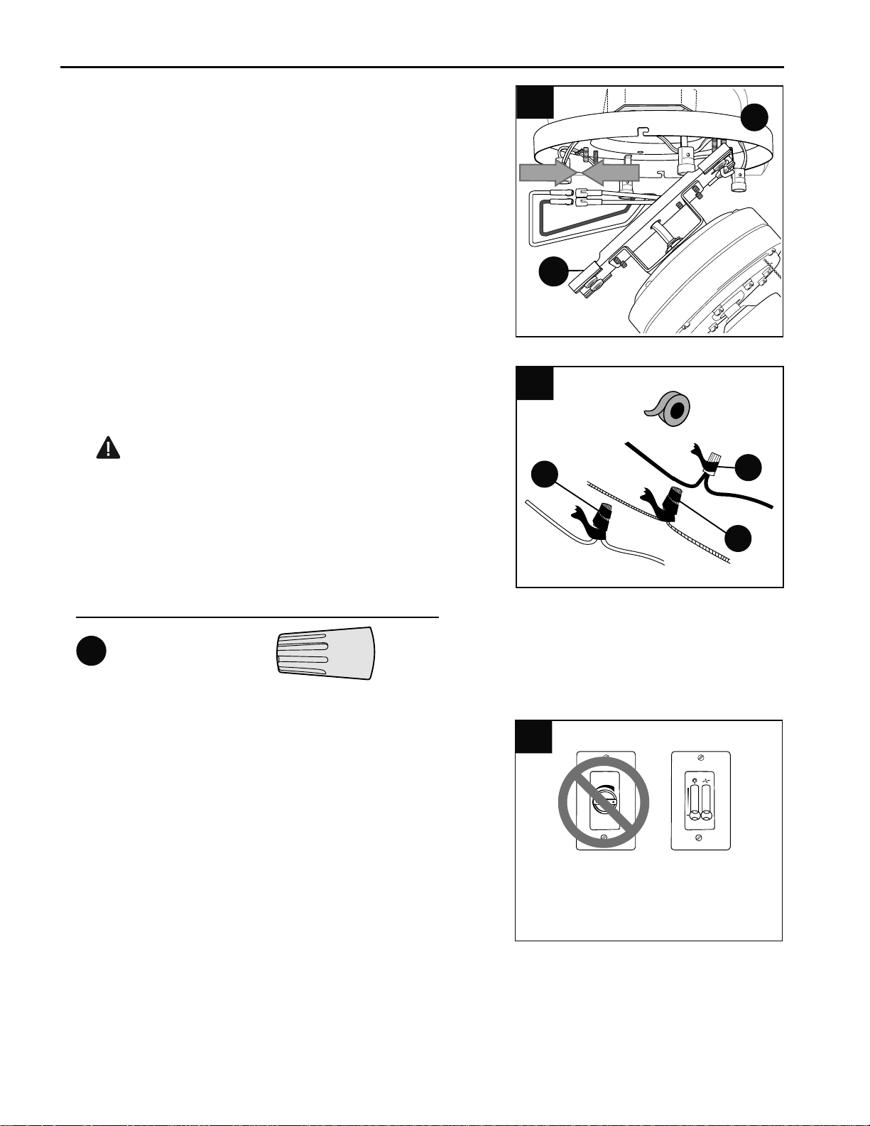
Locate the two WHITE wires labeled "INTERIOR
LIGHT" in the mounting plate (A) and the two molex
connections (one RED wire, one WHITE wire) at the
top of the motor assembly (B) and connect these
wires. (Fig. 2) Make sure that molex connections are
secure.
2.
2
B
A
IMPORTANT: Using a full range dimmer switch to
control fan speed will cause a loud humming noise
from fan. To reduce the risk of fire or electrical shock,
do NOT use a full range dimmer switch to control fan
speed. (Fig. 4)
*PLEASE NOTE: Must have third wire in wall to use
wall control (speed switch) such as the one shown at
right.
4
1
2
3
Dimmer
Switch
Speed
Switch
For illustrative purposes only--not
intended to cover all types of controls
4.
Loading ...
Loading ...
Loading ...