Loading ...
Loading ...
Loading ...
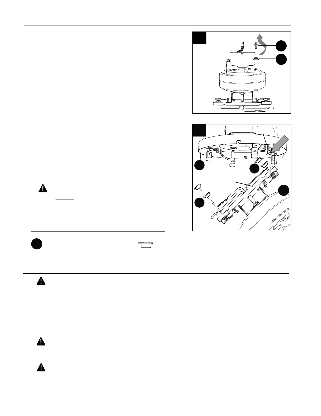
7
A
"J" Hook
Bar
B
INITIAL INSTALLATION
6
Locate holes that are reinforced with black rubber
in bar at top of motor assembly (B). Insert one
bushing (GG) into each of these holes. (Fig. 6)
Now, using the SLOTTED hole in the bar at the top
of the motor assembly (B), slide the bar over the "J"
hook on the mounting plate (A)--this will support the
fan during wiring. (Fig. 6)
WARNING: To reduce the risk of personal
injury, do not use any of the other holes in the bar
at the top of the motor assembly (B) to hang the
motor assembly (B) on the mounting plate (A).
6.
Caution: Be sure wiring box is properly
grounded and that a ground (green or bare) wire is
present.
WIRING
Warning: If house wires are different colors than
referred to in the following steps, stop immediately. A
professional electrician is recommended to determine
wiring.
WARNING: To reduce the risk of fire, electrical
shock, or personal injury, wire connectors provided
with this fan are designed to accept only one 12
gauge house wire and two lead wires from the fan. If
your house wire is larger than 12 gauge or there is
more than one house wire to connect to the two fan
lead wires, consult an electrician for the proper size
wire connectors to use.
5.
Remove motor screws (J) and lock washers (K)
from underside of motor and save for blade arm
(D) attachment later on. (Fig. 5)
5
K
J
Bushing x4
Hardware Used
GG
GG
GG
Loading ...
Loading ...
Loading ...