TO AVOID FIRE SHOCK OR DEATH; TURN OFF POWER at circuit breaker or fuse when servicing, installing or removing fixture.
To be installed and/or used in accordance with electrical codes and regulations.
If you are unsure about any part of these instructions, consult an electrician.
vizia +™ electronic switches are not compatible with standard 3-way or 4-way switches. They must be used with compatible vizia +™ on/off remotes.
Recommended minimum wall box depth is 2-1/2".
Use only one (1) vizia +TM digital timer switch in a multi-location circuit with up to 9 coordinating remote switches (without LEDs) or up to 4 matching remote switches (with LEDs).
Maximum wire length from digital timer switch to all installed remotes cannot exceed 300 ft (90 m).
Use this device with copper or copper clad wire only.
Tools needed to install your Timer Switch
Slotted/Phillips
Screwdriver
Pencil
Electrical Tape
Cutlers
Pliers
Ruler
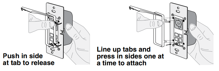
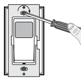
Changing the color of your device
Your device may include color options. To change color of the face, proceed as follows:
Installing your Timer Switch
NOTE: Use check boxes when Steps are completed.
Step 1: WARNING: TO AVOID FIRE SHOCK OR DEATH; TURN OFF POWER at circuit breaker or fuse and test that power is off before wiring!
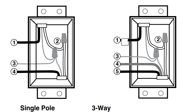
Step 2: Identifying your wiring application (most common):
NOTE: If the wiring in your wall box does not resemble any of these configurations, consult a qualified electrician.
Single Pole
Line (Hot)
Neutral
Ground
Load
3-Way
Line or Load (see important instruction below)
Neutral
Ground
First Traveler – note color
Second Traveler – note color.
NOTE: For matching remotew/LEDs installation, the First Traveler becomes Line Hot.
IMPORTANT : For 3-Way applications, note that one of the screw terminals from the old switch being removed will usually be a different color (Black) or labeled Common. Tag that wire with electrical tape and identify as the common (Line or Load) in both the switch wall box and remote wall box.
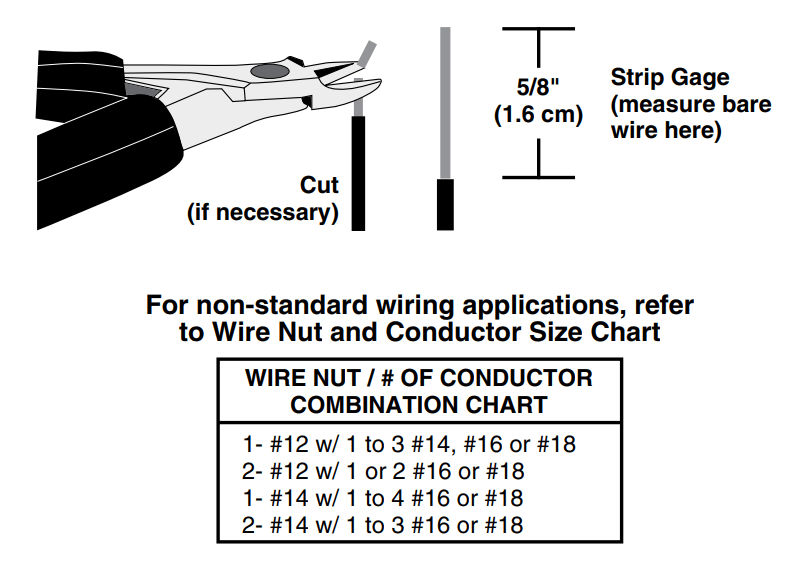
Step 3: Preparing and connecting wires:
Pull off pre-cut insulation from timer leads. Make sure that the ends of the wires from the wall box are straight (cut if necessary). Remove insulation from each wire in the wall box as shown.
Make sure that the ends of the wires from the wall box are straight (cut if necessary).
Remove insulation from each wire in the wall box as shown.
For Single-Pole Application, go to Step 4a.
For 3-Way Coordinating Remote (no LEDs) Application, go to Step 4b.
For 3-Way Matching Remote (with LEDs) Application, go to Step 4c.
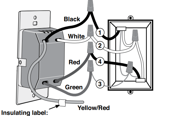
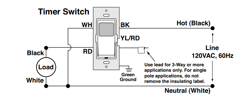
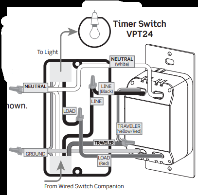
Step 4a Single Pole Wiring Application:
Insulating label: This wire is used in 3-way installations only. For single pole installations, do not remove insulating label.
WIRING TIMER SWITCH:
Connect wires per WIRING DIAGRAM as follows:
Green or bare copper wire in wall box to timer switch Green lead.
Line Hot wall box wire to timer switch Black lead.
Load wall box wire to timer switch Red lead.
Line Neutral wall box wire to timer switch White lead.
NOTE: If label is missing place electrical tape around the timer switch Yellow/Red lead. Ensure no strands are exposed.
Proceed to Step 5.
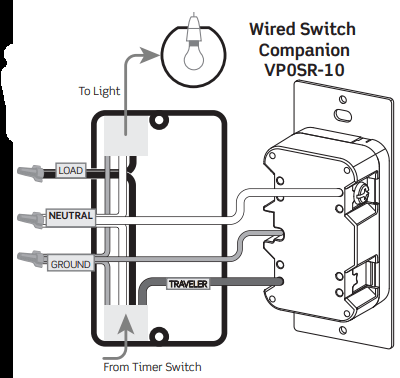
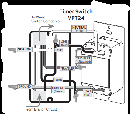
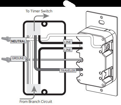
Step 4b: 3-Way Wiring with Wired Switch Companion, VP0SR-10, (no Indicator Light) Application:
WIRING SWITCH COMPANION (VP0SR-10):
“BK” and “RD” terminals on wired switch companion are unused. Tighten both screws.
WIRING TIMER SWITCH:
The timer switch must be installed in a wall box that has a LINE (Hot) connection. • Proceed to page 7.
NOTE: Maximum wire length from timer to all installed wired switch companion cannot exceed 300 ft (90 m)
Step 4c: 3-Way Wiring with Wired Switch Companion, VP0SR-10, (no Indicator Light) Application:
NOTE: The timer switch must be installed in a wall box that has a LOAD connection. The wired switch companion must be installed in a wall box with a LINE (Hot) connection and a NEUTRAL connection. A NEUTRAL wire to the wired switch companion needs to be added as shown.
NOTE: Maximum wire length from timer to all installed wired switch companion cannot exceed 300 ft (90 m).
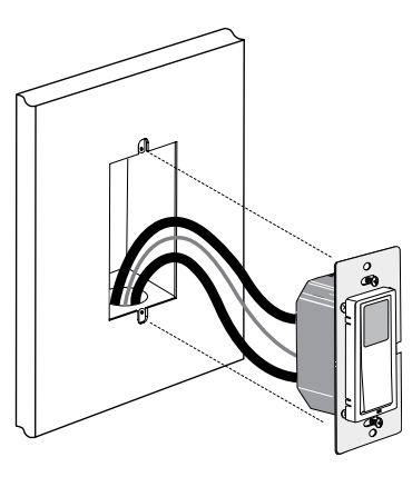
Step 5 Testing your Switch prior to mounting in wall box:
Position all wires to provide room in outlet wall box for device.
Ensure that the word “TOP” is facing up on device strap.
Partially screw in mounting screws in wall box mounting holes.
NOTE: Dress wires with a bend as shown in diagram in order to relieve stress when mounting device.
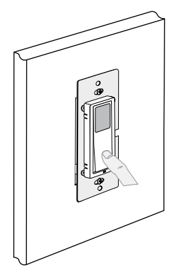
Restore power at circuit breaker or fuse.
Wait until or lime is displayed on the screen.
Press pad until locator light is OFF. Load should turn ON
If loads do not turn ON, refer to the TROUBLESHOOTING section.
Step 6: Switch Mounting: TURN OFF POWER AT CIRCUIT BREAKER OR FUSE
Installation may now be completed by tightening mounting screws into wall box. Attach wallplate
Step 7: Restore Power:
Restore power at circuit breaker or fuse.
Installation is complete.
NOTE: The Digital Timer Switch is equipped with an intei rechargeable battery back-up to keep programmed settir in the event of a power interruption.
OPERATION
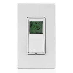
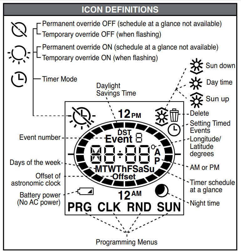
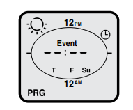
Timer Schedule at a Glance will allow you to quickly see your timers
ON/OFF settings for the day. The displayed segments represent the time(s) your load will be on. The segment representing the current time will be flashing.
Backlit LCD display will light up when any button is pressed and will extinguish 30 seconds after the last button press.
PROGRAMMING GUIDE
Decide which mode is best for your application:
Pro mode or Standard mode
Pro Mode provides up to 50 ON/OFF events for any day or combination of days. M-Su. M-F. or Sa-Su at desired fixed times or self adjusting Sunup and Sundown times. In this mode self adjusting
Daylight Savings Time and random modes are also available.
Std Mode provides up to 3 ON/OFF events for M-Su. M-F. or Sa-Su at desired fixed times only. Self adjusting Sunup and Sundown and
Daylight Savings Time are NOT available in Standard Mode.
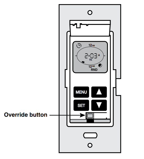
To exit programming at any time press override button
To program your device:
a) Perform a System Reset by gently lifting the VPT24 door from the bottom of the push pad until an audible click is heard. The door will stay open while you are programming the device:
b) Press and hold followed by (Override) until stops flashing and flashes (approximately 5 seconds).
Pressto confirm device Reset.
c) Product will go through a brief self test and then will begin to flash. Choose or by using or until the selected mode appears and pressing to confirm your choice.
d) Continue to the programming section for the Mode chosen.
PROGRAMMING PRO MODE
1. Setting up the Time. Daylight Savings Time Option and the Date:
will be flashing. Press or to select the hour and press to confirm your choice. will be flashing.
will be flashing. Press orto select the minutes and press to confirm your choice.
A or P will be flashing. Press orto select A for AM or P for PM and pressto confirm your choice.
will be flashing. Set the daylight savings time mode to OFF or AUTO (for automatic adjustment of daylight savings time) by using or to choose daylight savings time option and press to confirm your choice. NOTE: Daylight Savings Time shall start at 2am on the second Sunday of March (add one hour) and end at 2am on the first Sunday of November (subtract one hour).
will be flashing. Use or to choose the year and press to confirm your choice.
will be flashing. Use or to choose the month and press to confirm your choice
will be flashing. Use or to choose the date and pressto confirm your choice. The day of week will automatically adjust.
2. Programming your Timer Options:
Setting Sunup. Sundown. desired Offset Time and Time Zone:
Sunup and Sundown are automatically adjusted using the latitude and longitude coordinates of your location. To obtain these coordinates go to leviton/VPT24 and click on Longitude/ Latitude Coordinates Lookup Type in your home address and press enter. Your latitude (N) and longitude (W) coordinates will be shown on the screen. Write down only the 2 or 3 digit number.
Disregard a negative symbol (-) if it preceeds the number.
The time zones are limited to the North American Continent. The options you are presented are determined via your longitude in the chart below:
On your timer press until SUN appears at the bottom of the screen and press to confirm your choice.
Use or to choose your latitude (N) and press to confirm your choice.
Use or to choose your longitude (W) and press to confirm your choice.
will be flashing to represent the offset time. Choose the amount of time. if any. to turn the load ON/OFF before or after Sunup and Sundown by pressing to add time to the Sunup/ Sundown time and use to subtract time from the Sunup/ Sundown time. Press to confirm your choice (up to 3 hours and 59 minutes).
will appear. The time zone closest to the coordinates you entered will flash. Press if this is correct. If this is not correct use or to choose your time zone and press to confirm your choice.
b. Setting ON/OFF Events:
Press until PRG is in the lower left corner. Press to enter the programming mode.
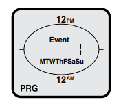
Event 1 will be flashing. Press to choose this event or use to move to the next event and press to confirm your event number choice.
All days of the week will be flashing. Press to choose all days of the week or use or to scroll through M-F. Sa Su. any single day or combination of days. NOTE: To choose a combination of days press after each day you want and then move on to the next day by pressing or . Continue to scroll using until PRG flashes.
When done choosing the desired days PRG in the lower left corner will flash. Press to confirm the chosen days and continue on to choosing the event TURN ON TIME.
At use or to choose for time. for Sundown. for Sunup or to delete an existing program and press to confirm your choice.
If is chosen. use or to choose the hour and press to confirm your choice. Do the same for minutes.
At 6:00P press to choose a TURN OFF TIME or use or to choose for Sundown. for Sunup orto delete an existing program and press to confirm your choice.
If is chosen. use or to choose the hour and press to confirm your choice. Do the same for minutes.
Continue to set desired events in the same manner. When this is done press to escape out of programming. If no buttons are pressed after approximately 30 seconds the device will automatically exit out of programming mode.
PROGRAMMING STANDARD MODE
To set the clock:
will be flashing. Use or to choose the hours. Pressto confirm your choice.
The minutes will be flashing. Use or ) to choose the minutes. Press to confirm your choice.
A for AM or P for PM will be flashing. Use or to choose the
A or P. Press to confirm your choice.
The day of the week will be flashing. Use or to choose the day. Press to confirm your choice.
To set ON/OFF Events:
Press until PRG is in the lower left corner. Press to enter the programming mode.
Event 1 will be flashing. Press to choose this event or use to move to the next event and press to confirm your event number choice.
All days of the week will be flashing. Press to choose all days of the week or use or to scroll through M-F and Sa-Su. Press to confirm your days of the week choice and continue to program the event ON TIME.
At use or to choose for time. or to delete an existing program and press to confirm your choice.
Use or to choose the hour and press to confirm your choice. Do the same for minutes and press to confirm your choice. Continue to program the event OFF TIME.
At 6:00P press to choose the OFF TIME or use or to choose to delete an existing program and press to confirm your choice.
Continue to set desired events in the same manner. When you are done press to escape out of programming. If no buttons are pressed after approximately 30 seconds the device will automatically exit out of programming mode.
TIMER OVERRIDES
Activate Temporary Override by pressing the push pad to toggle the load (ON to OFF or OFF to ON).
Activate Permanent Override by pressing and holding the push pad for several seconds to maintain the load in the current state (either ON OFF).
HANGING SETTINGS
Press until CLK appears at the bottom of the screen . Press to enter this mode. Adjust the clock using or and pressing after each setting.
Turning Random Mode ON/OFF (Pro Mode ONLY):
This function will add or subtract anywhere from 1 to 20 minutes to each selected ON and OFF time to create a random pattern.
Press until RND appears at the bottom of the screen and press to enter this mode.
Use or to toggle between and press to confirm your choice.
DELETE ALL EVENTS
If at any time you want to delete all of your programmed events. you can perform a DELETE ALL EVENTS function:
Gently lift the VPT24 door from the bottom of the push pad until an audible click is heard.
Press and hold followed by (Override) until stops flashing. Upon releasing both buttons all events will be deleted and the Timer Schedule at a Glance will appear with only the current time segment flashing.
USE IN MULIT-LOCATION APPLICATIONS
When using a remote switch(es) with your vizia +™ 24 hour timer you will be able to activate the temporary override or the permanent override from the remote switch. To activate or deactivate the temporary override press the push pad on the remote switch. To activate permanent override press and hold the remote switch push pad. Either of these actions will toggle the state of the load.
TROUBLESHOOTING
Lights flickering or intermittent power to load
Load has a bad connection.
Wires not secured firmly with wire connectors of timer switch or terminal screws of remote.
Load does not turn ON and Locator LED does not turn ON
Circuit breaker or fuse has tripped.
Load is burned out.
Load Neutral connection is not wired.
Remote does not operate lights
Ensure that total wire length does not exceed 300 ft (90 m).
Wired switch companion does not operate lights:
Ensure that total wire length does not exceed 300 ft. (90 m).
NOTE: The timer switch must be installed in a wall box that has a LOAD connection. The wired switch companion must be installed in a wall box with a LINE (Hot) connection and a NEUTRAL connection. A NEUTRAL wire to the wired switch companion needs to be added as shown.
#1 How does one program a repeat event? (10 minutes off, 5 minutes on , start on top of the hour, repeat forever)
Unfortunately, if we understand you correctly, this timer will not work for that, as it is not a duty cycle timer. You would need 4 on/off events per hour for the "5 minutes on" part, and that would be 4 events x 24 hours for 96 events. Even on the PRO mode, this timer only supports up to 50 manual programmed events.
#2 If there is a power outage will this switch need to be reprogrammed?
This device features a battery to help store its programs during power outages
#3 I want it to go on 30 min after sunset, off 30 min before sunup. Techline says no; offset is either + or - X mins for both times. Any suggestions?
This CAN easily be accomplished (I did it myself). Although the single offset always applies to BOTH sunset and sunrise, you can easily trick the device to use one event to turn on after sunset an turn off before sunup. To elaborate on J. Barton's recommendation, use a latitude/longitude from a different location that has sunset/sunrise times that match your goal. When doing so, be sure to use a lat/long within the same timezone to ensure the daylight savings settings remain accurate. In my case I wanted the lights to turn on 30-45 minutes before sunset then off 30-45 minutes after sunrise to ensure plenty of light at dusk/dawn. I live in Texas but used South Dakota lat/long because their sunset is before Texas and their sunrise is after Texas (they have shorter days - perhaps they should move to Texas!). Not only does this trick solve the problem, but it is easier to program because it only requires 1 event and does not require programming an offset. This is THE solution.
#4 How do i switch between events? i am using std mode and have set event 1 and event 2 with different time intervals, how do i switch the events?
The timer will run each of your events concurrently. You will see the day's events illuminated in the schedule at a glance ring if multiple events are set for a single day.
 when Steps are completed.
 or
or 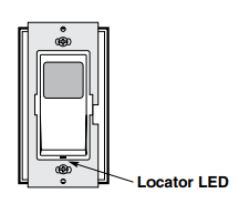
 or Standard mode

 followed by
  (Override) until
  stops flashing and
  flashes (approximately 5 seconds).
 will begin to flash. Choose
  or
or  by using
 or
or until the selected mode appears and pressing
  will be flashing. Press
  will be flashing. Press
 will be flashing. Set the daylight savings time mode to OFF or AUTO (for automatic adjustment of daylight savings time) by using
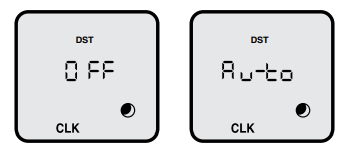
 will be flashing. Use
 will be flashing. Use
 will be flashing. Use
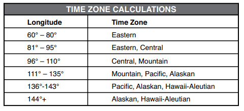
 until SUN appears at the bottom of the screen and press
  to confirm your choice.
 will be flashing to represent the offset time. Choose the amount of time. if any. to turn the load ON/OFF before or after Sunup and Sundown by pressing
  will appear. The time zone closest to the coordinates you entered will flash. Press if this is correct. If this is not correct use
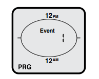
 use
use  for Sundown.
  for Sunup or
  to delete an existing program and press
  to escape out of programming. If no buttons are pressed after approximately 30 seconds the device will automatically exit out of programming mode.
 until PRG is in the lower left corner. Press to enter the programming mode.
 use
use to delete an existing program and press
 . Press
  and
and  press
press