Loading ...
Loading ...
Loading ...
OPERATING PROCEDURE
PHOTOS/FIGURES
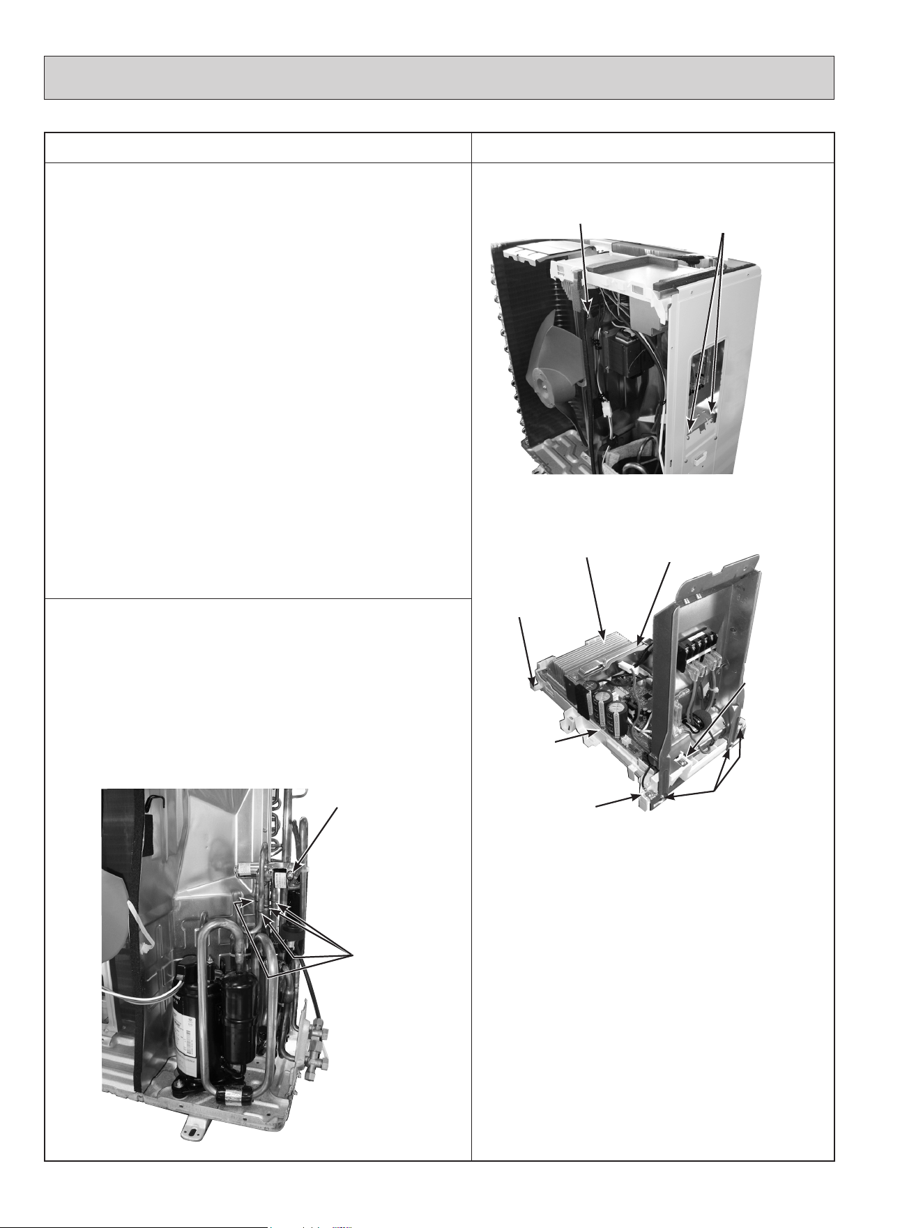
2. Removing the inverter assembly, inverter P.C. board
(1) Remove the cabinet and panels. (Refer to section 1.)
(2) Disconnect the lead wire to the reactor and the following con-
nectors:
<Inverter P.C. board>
CN721 (R.V. coil) (MUZ)
CN722
(Defrost heater and heater protector) (MUZ-GL18NAH)
CN931, CN932 (Fan motor)
CN641 (Defrost thermistor (MUZ) and discharge temperature
thermistor)
CN643 (Ambient temperature thermistor)
CN644 (Outdoor heat exchanger temperature thermistor)
CN724 (LEV)
(3) Remove the compressor connector.
(4) Remove the screw fixing the heat sink support and the sepa-
rator.
(5) Remove the fixing screws of the terminal block support and
the back panel.
(6) Remove the inverter assembly.
(7) Remove the screw of the ground wire, screw of the P.C.
board cover and screws of the terminal block support.
(8) Remove the heat sink support from the P.C. board support.
(9) Remove the screw of the inverter P.C. board and the inverter
P.C. board from the P.C. board support.
Photo 5
Photo 6
3. Removing R.V. coil (MUZ)
(1) Remove the cabinet and panels. (Refer to section 1.)
(2) Disconnect the following connector:
<Inverter P.C. board>
CN721 (R.V. coil) (MUZ)
(3) Remove the R.V. coil.
Photo 7
70
Screw of the heat sink
support and the separator
Brazed parts of
4-way valve
Screw of
the R.V. coil (MUZ)
Heat sink
Screw of
the inverter
P.C. board
Screw of the
ground wire
Screws of the
terminal block
support
Screw of the
P.C. board
cover
Screws of the terminal
block support and the
back panel
P.C. board
support
Heat sink
support
OBH733J
Loading ...
Loading ...
Loading ...