Loading ...
Loading ...
Loading ...
50
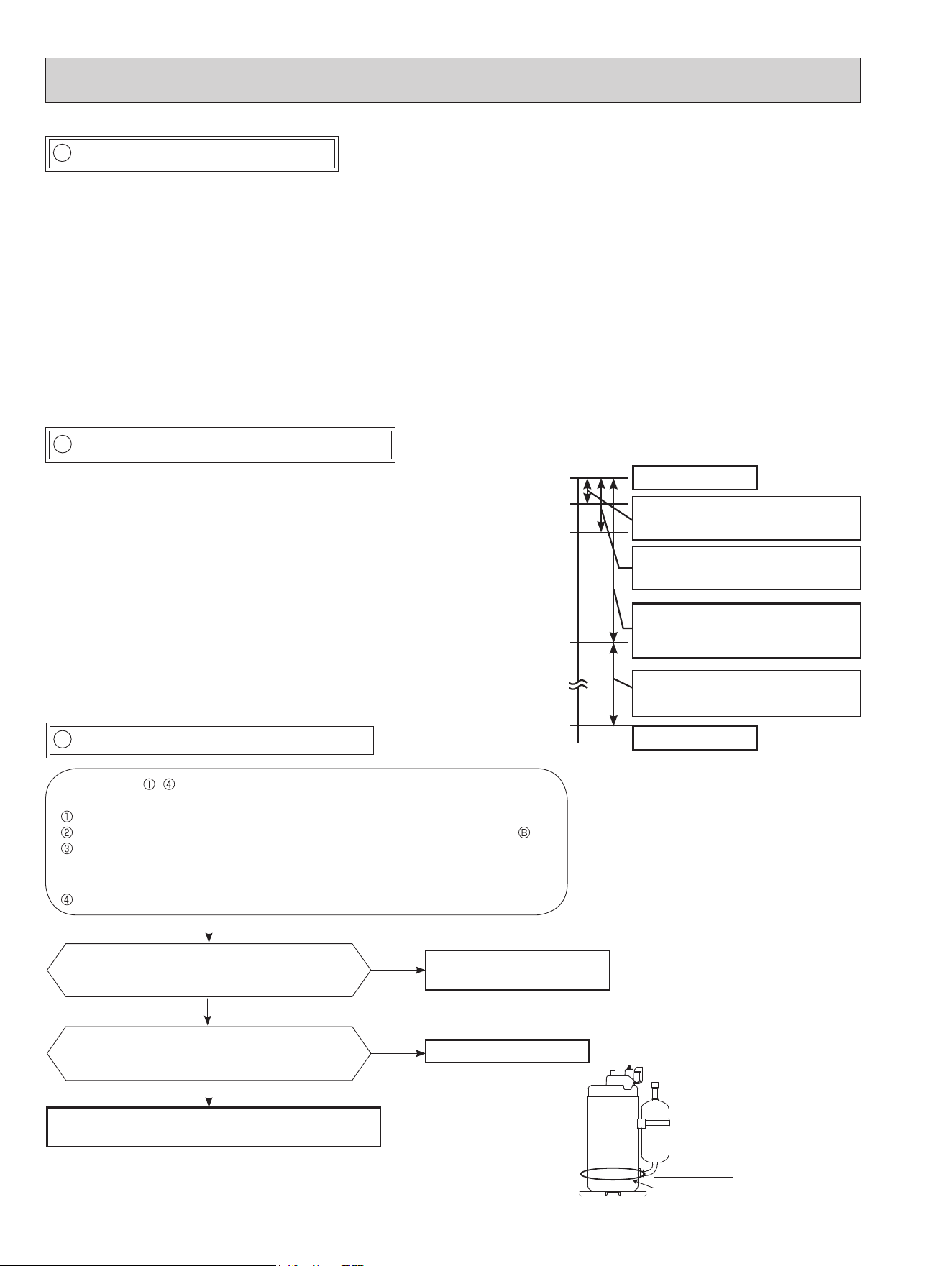
F Check of compressor start failure
D Check of compressor winding
E Check of compressor operation time
●Disconnect the connector between the compressor and the power module (IC700) (MUZ-GL09/12/15/18, MUY-GL09/12/15/18)/
IGBT module (IC700) (MUZ-GL24, MUY-GL24), and measure the resistance between the compressor terminals.
<<Measurement point>>
At 3 points
BLK-WHT
BLK-RED
WHT-RED
<<Judgement>>
Refer to 10-4.
0 [Ω] ················Abnormal [short]
Infinite [Ω] ·······Abnormal [open]
NOTE: Be sure to zero the ohmmeter before measurement.
*Measure the resistance between the lead wires at 3 points.
After the compressor is heated with a drier,
does the compressor start? *1
Replace the compressor.
Compressor start failure. Activate pre-heat control.
(Refer to 9-2. "PRE-HEAT CONTROL SETTING")
No
Yes
Does the compressor run for 10 seconds or
more after it starts?
Check the refrigerant circuit.
Check the stop valve.
Yes
No
*1
Heat the compressor with
a drier for about 20 minutes.
Do not recover refrigerant
gas while heating.
Heating part
● Connect the compressor and activate the inverter. Then measure
the time until the inverter stops due to overcurrent.
<<Operation method>>
Start heating or cooling operation by pressing EMERGENCY
OPERATION switch on the indoor unit. (TEST RUN OPERATION:
Refer to 7-6.)
<<Measurement>>
Measure the time from the start of compressor to the stop of
compressor due to overcurrent.
Compressor starts
Abnormal
(IC700 failure)
(Compressor winding short)
Abnormal
(Compressor lock out)
(Starting defect)
Abnormal
(Poor contact)
(Inverter P.C. board defect)
(Disconnected connector)
Abnormal
(Refrigerant circuit defect)
(Closed valve)
Normal
0 second
1 second
2 seconds
10 seconds
10 minutes
<<Judgement>>
Conrm that ~ is normal.
•Electrical circuit check
. Contact of the compressor connector
. Output voltage of inverter P.C. board and balance of them (See 10-5. )
. Direct current voltage between DB61(+) and (-) (MUZ-GL09/12/15/18,
MUY-GL09/12/15/18)/ JP715(+) and JP30(-) (MUZ-GL24, MUY-GL24), on
the inverter P.C. board
. Voltage between outdoor terminal block S1-S2
OBH733J
Loading ...
Loading ...
Loading ...