QUICK SETUP GUIDE
Standing Desk
NSSDSKBL / NSSDSKMH / NSSDSKAK
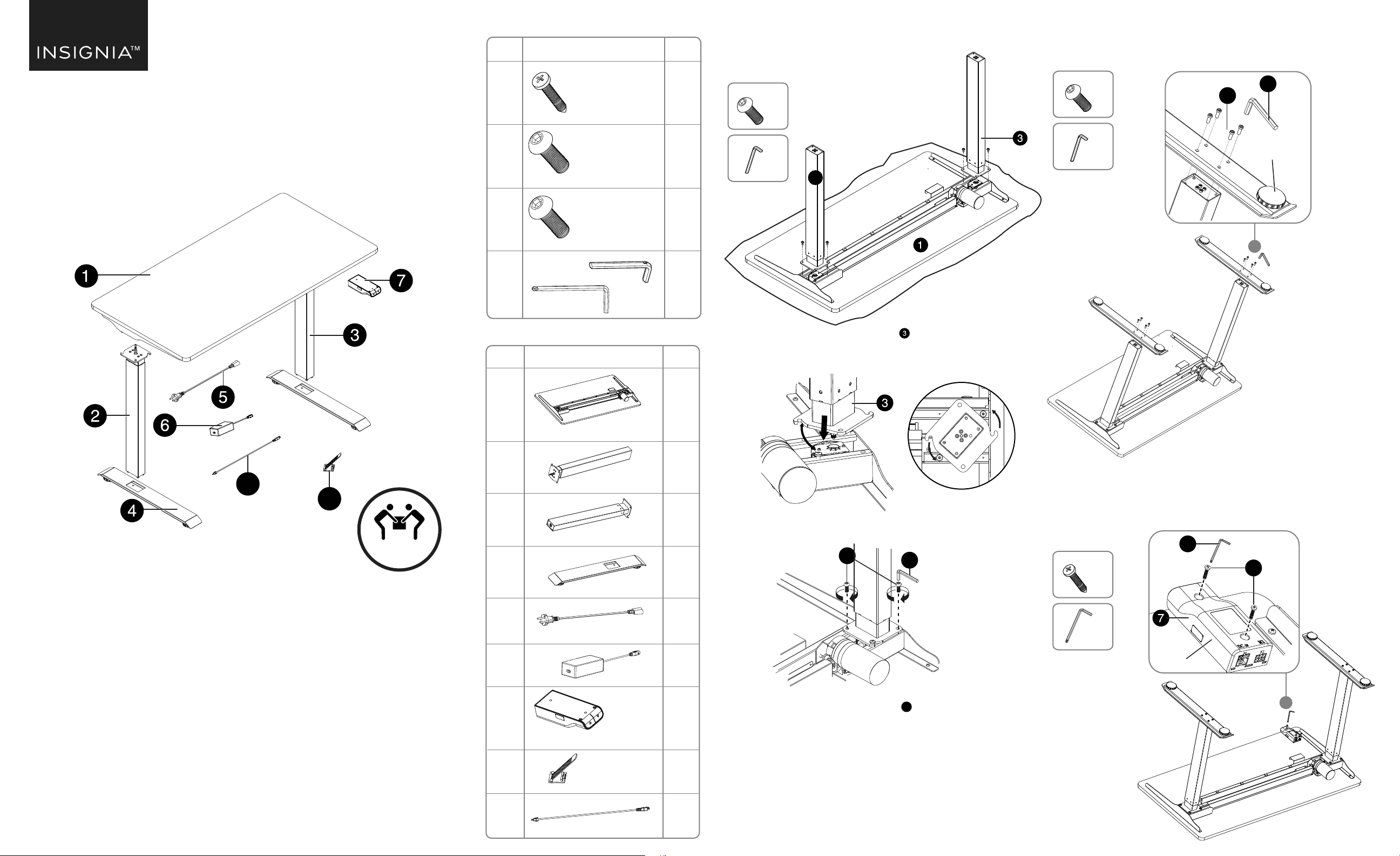
MAJOR PARTS LIST
SMALL PARTS LIST
No. Part Qty
A 2
B 4
C 8
D 1
M6 x16
ST4.2*19
M6×16
4 x 4
5 x 5
No. Part Qty
1 1
2 1
3 1
4 2
5 1
6 1
7 1
8 4
9 1
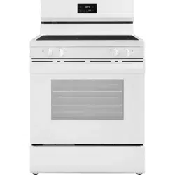
Tabletop
Left column
Right column
Feet
Power Plug
Adapter
Cable ties
Hand switch
D
C
× 8
A
D
× 2
5 × 5
4 × 4
× 4
4 × 4
C
D
Before using your new product, please read these instructions to prevent any damage.
PACKAGE CONTENTS
• Standing desk
• Small parts list
• Quick Setup Guide
FEATURES
• Easily adjusts to a comfortable height with a hand switch
• 19.7 in (50 cm) of height adjustment lets you use the desk while standing or sitting
• The desktop holds up to 110 lbs. (50 kg) and is suitable for a computer, printer, or
sewing machine (within the weight limit)
• Cable management for a clean look
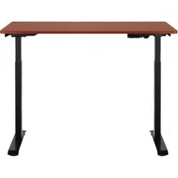
• Choice of two colors, black or mahogany (both with black frame)
• Electric adjustment switch easily raises or lowers the desk height
• Steel frame with particleboard tabletop provides a stable work surface
Top view
D
INSTALLING THE LEGS
1 Place the desktop upside down on a carpet or protective cloth.
Note: Make sure that both legs are at their lowest setting
(turn the shaft in each leg to do this) before installation so
that the table will be level when assembled.
2 Insert the hexagonal shaft in the rst leg into the corresponding hole in
the desktop leg mount, then turn the leg until the screw holes line up and the
connecting cable on the top of the leg faces the in toward the motor.
3 Attach the leg to the desktop with four M6 × 16 screws, tightening them
rmly with the 4 × 4 Allen key.
4 Repeat the steps to attach the other leg 2 .
Note: See the section on “Installing the Adapter and Connecting the Cables” for cable
connections.
D
C
Adjustable pad
Hand switch
D
B
2
INSTALLING THE FEET
Attach the feet to the bottoms of the legs with four 6 × 16 screws each. Make
sure that the adjustable pads on the bottom of the feet face down and the long
portion of each foot faces forward (as shown).
INSTALLING THE SWITCH
Attach the switch to the bottom of the desktop with two ST4.2*19 screws.
Tighten the screws with the 5 × 5 Allen key. Make sure that the at side of the
switch is against the desktop and the UP and DOWN buttons are facing forward.
B
TWO PERSON
LIFT REQUIRED
8
9
2
D
A
Adapter cable
V3 ENGLISH 21-0523
LEGAL NOTICES
FCC PART 15
This device complies with Part 15 of the FCC Rules.
Operation of this product is subject to the following two conditions:
(1) this device may not cause harmful interference, and (2) this device must accept any interference
received, including interference that may cause undesired operation.
This equipment has been tested and found to comply within the limits for a class B digital device,
pursuant to Part 15 of the FCC Rules. These limits are designed to provide reasonable protection against
harmful interference in a residential installation. This equipment generates, uses, and can radiate radio
frequency energy and, if not installed and used in accordance with the instructions, may cause harmful
interference to radio communications. However, there is no guarantee that interference will not occur in a
particular installation. If this equipment does cause harmful interference to radio or television reception,
which can be determined by turning the equipment o and on, the user is encouraged to try to correct
the interference by one or more of the following measures:
• Reorient or relocate the receiving antenna.
• Increase the separation between the equipment and receiver.
• Connect the equipment into an outlet on a circuit dierent from that to which the receiver is connected.
• Consult the dealer or an experienced technician for help.
FCC WARNING
Changes or modications not expressly approved by the party responsible for compliance with the FCC
Rules could void the user’s authority to operate this equipment.
ONEYEAR LIMITED WARRANTY
For complete warranty, visit www.insigniaproducts.com.
CONTACT INSIGNIA
1-877-467-4289 (U.S. and Canada) or 01-800-926-3000 (Mexico)
www.insigniaproducts.com
INSIGNIA is a trademark of Best Buy and its aliated companies
Distributed by Best Buy Purchasing, LLC
7601 Penn Ave South, Richeld, MN 55423 U.S.A.
©2021 Best Buy. All rights reserved.
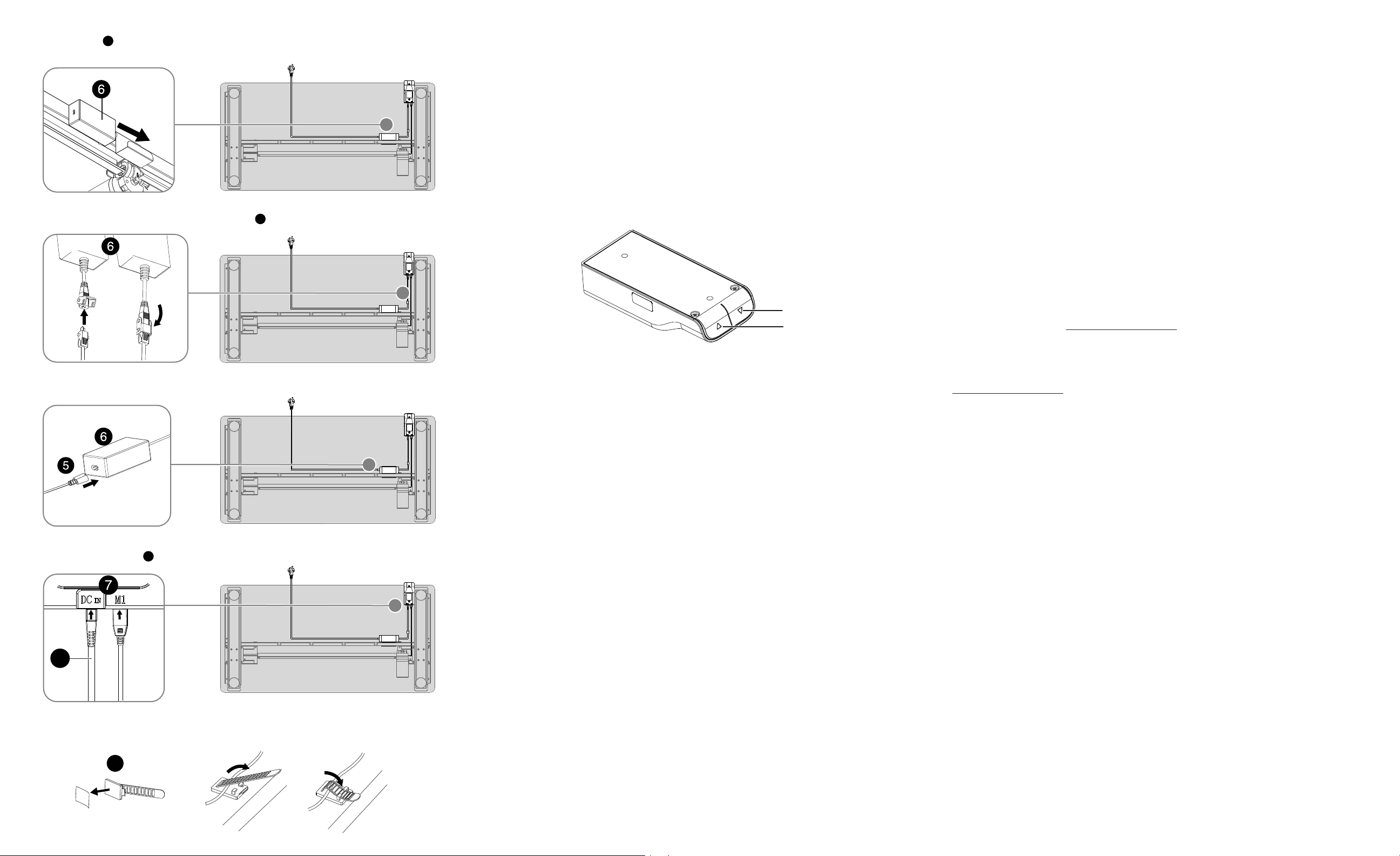
INSTALLING THE ADAPTER AND CONNECTING THE CABLES
1 Slide the adapter into the slot on the bottom of the desktop so that the female connector is on the left
(as shown) and the adapter cable Is on the right (see detail).
2 Connect the cable from the switch to the adapter cable , then lock them together (see detail).
3 Plug the small connecter on the power cord into the female connector on the adapter (see detail).
4 Connect the adapter cable to the DC port. Connect the motor cable to the M1 port (see detail).
5 Attach the cables to the bottom of the desktop with the cable ties provided (see detail).
USING YOUR STANDING DESK
1 With another person to assist you, lift the desk from the oor and turn it upright.
2 Place the desk where you want it, on a rm, level oor.
3 Plug your desk into a power outlet.
4 Press the
to raise the desktop and press the
to lower the table top.
Note: Make sure that the table and surrounding area are clear from obstructions before moving the table up or down.
Reset
• At the lowest position, press and hold the down button (longer than 5 seconds) to reset the lifting system.
When the lifting system bottoms out, rebounds, then stops, the reset is successful.
• If the lifting system fails, release the button, then press and hold the down button (longer than 5 seconds).
When the lifting system bottoms out, rebounds, then stops, the reset is successful.
Anti-collision function:
Note: When the lifting system’s built-in sensor encounters resistance, the lifting system pauses, then reverses motion and
stops.
• Press and hold the
and
buttons together (longer than 5 seconds) to turn o or turn on the
anti-collision function.
SPECIFICATIONS
• Maximum weight: 110 lbs. (50 kg)
• Input voltage required: 100-240 v ~ 50/60 Hz
• Lowest position: 28.7 in. (73 cm)
• Highest position: 48.4 in. (123 cm)
• Dimensions (desktop size) (H×W×D): 47.2 × 23.6 × 0.7 in. (120 × 60 × 1.8 cm)
TROUBLESHOOTING
The tabletop will not raise or lower
• Make sure that all cables are securely connected.
• Make sure that the tabletop is not overloaded. The maximum weight should not exceed 110 lbs. (50 kg).
• Try again after 30 minutes.
• Contact your supplier or dealer.
IMPORTANT SAFETY INFORMATION
• You should only use your table when the temperature is between 32 - 104° F (0-40° C).
• The power adapter requires 100-240 VAC ~ 50/60 Hz.
• Do not expose the power adapter to moisture, or excessive dust. It may cause shock hazards.
• Operate the adapter in a well ventilated area. Maximum ambient temperature around the power adapter
must not exceed 104° F (40° C).
• Do not open the power adapter under any circumstances. The power adapter is not intended to be
repaired in case of failure or component defect. There are no internal serviceable parts.
• Discontinue use, if any of the following should occur:
• The adapter shuts down when it connects to the switch’s port. (LED turns o)
• The adapter's LED light blinks when the adapter is plugged into an AC power outlet.
• A cord or plug is damaged or frayed.
• Make sure to connect the adapter’s plug and switch’s port correctly.
• The socket shall be installed near the adapter and shall be easily accessible.
• Make sure that your table is correctly and completely assembled before you use it.
CAUTION: You should unplug the power cord before cleaning your table. Wipe the dust from the surface
with a slightly damp cloth. Do not use caustic or abrasive cleaners or any solvents (such as benzine or
gasoline) to clean your table.
CAUTION: Children should not be allowed to operate the table.
8
UP button
DOWN button
6
6
6
9