XL
XleratorManual3-11.doc
FOR PROPER ELECTRICAL CONNECTIONS, CHECK YOUR LOCAL BUILDING CODES.
YOUR UNIT MUST BE INSTALLED BY A QUALIFIED, LICENSED ELECTRICIAN.
PARTS LIST FOR XLERATOR DRYER
REF NO.
DESCRIPTION
XL 1 Cover (includes Nameplate)
XL 2 Nameplate
XL 3 Tamper-proof Bolt
XL 4 Tamper-proof Wrench
XL 5 Air Outlet (includes gasket)
XL 6 Terminal Block (includes screws)
XL 7 Control Assembly & Sensor
XL 8 Heating Element Assembly
XL 9 Motor Assembly
XL 10 Wall Plate Assembly
XL 11 Cover Mounting Brackets
XL 12 Housing Grommet
XL 13 Housing Retainer
XL 14 Recess Kit (for ADA)
XL 15 Optics Assembly (Sensor)
NOTE
: Model, Serial Number and Voltage of the
dryer MUST BE included when ordering parts.
NOTE: Upon completing installation and checking for proper operation, it is highly recommended that a bead of silicone sealant be placed around
the outside of the cover at the wall to protect dryer from internal corrosion caused by wash water and cleaning solutions
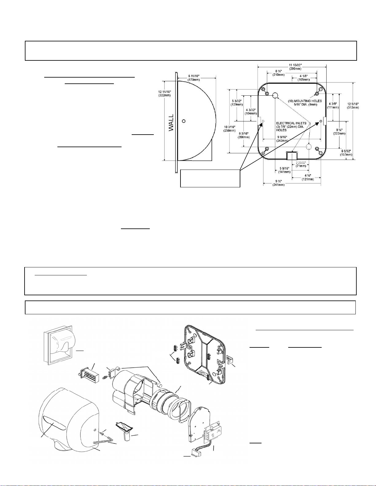
INSTALLATION INSTRUCTIONS FOR XLERATOR® HAND DRYER
1. Remove cover of dryer by unscrewing two tamper-proof bolts from the sides of the cover with the special wrench provided with each unit.
2. Attach wall plate at the four corners to smooth wall. In locations where vandalism is a concern, use the two additional mounting holes shown.
Remove control assembly to access right side mounting hole. Attach with the recommended type of fastener (see above).
3. Connect a 110/120V dryer to a 15 Amp. dedicated branch circuit using at least #12 GA copper wire. (Do not exceed a 20 Amp. branch circuit)
Connect a 208, 220/240V or 277V dryer to no more than a 15 Amp. dedicated branch circuit using at least a #14 GA copper wire.
Attach lines to terminals as indicated by the schematic inside dryer cover. Be sure that an equipment ground wire is securely fastened to green
ground screw on base plate. Dryers should be installed per local code requirements.
4. In multiple installations, before replacing cover, check the Serial Number marked inside the dryer to be sure it matches the Serial Number marked
on the label at the bottom of cover. PLEASE DO NOT SWITCH COVERS. Do not forget to leave the special TAMPER PROOF WRENCH with
the owner.
Suggested Mtg. Heights from floor
to bottom of dryer
Men’s 45“ (1143 mm)
Ladies’ 43“ (1092 mm)
Teenagers’ 41“ (1041 mm)
Sm. Children 35“ (889 mm)
Handicapped 37“ (940 mm)
IF MOUNTING OVER COUNTERTOP, DISTANCE FROM
COUNTER TO DRYER MUST BE 15” (381mm) MINIMUM
Recommended Fastener
Masonry Wall ½” expansion sleeve with ¼” lag bolt
Hollow Wall ¼” wing type through bolt
Wooden Wall ¼” lag screw with washer
LOCATION OF ADDED MTG
HOLES FOR MORE SECURE
INSTALLATION
INSTALLATION NOTE: If the dryer will not turn on, stays on or stops working, it may be mounted too close to a counter or object. Turn off the
power to dryer for 10 seconds and then reapply power. If dryer will start, then turn off again, relocate the object or remount dryer. If this is not
possible, adjust the range of the sensor by turning the range adjustment on the control board, counterclockwise to decrease sensor range.
Please call the factory at 1-800-255-9235 and one of our trained technicians will be happy to assist you.
XL14
XL1
XL2
(Location)
XL3
XL4
XL5
XL6
XL7
XL8
XL9
XL10
XL11 (2)
XL12 (4)
XL13 (4)
XL15
XL
XleratorManual3-11.doc
TROUBLESHOOTING YOUR DRYER
As with any electrical appliance, repairs to be performed by qualified service personnel
DISCONNECT ELECTRICAL SUPPLY TO DRYER PRIOR TO SERVICING
CLEANING INSTRUCTIONS
OUTSIDE
Gently wash cover (including air Inlet holes) using a soft cloth or sponge and a mild soap or detergent with lukewarm water to loosen dirt and grime.
INSIDE - CLEANING SHOULD BE PERFORMED BY QUALIFIED SERVICE PERSONNEL
With normal use, dryer will require cleaning once a year. Heavier usage requires more frequent cleaning. Lint on the air inlet or other internal
parts of dryer will reduce efficiency and shorten the life of the working parts. To clean, remove cover by unscrewing the tamper-proof bolts from cover
with the special wrench provided with each dryer. Use a small, soft brush to gently clean all parts.
5-YEAR LIMITED WARRANTY
1. This product is warranted to be free from defects for a period of five (5) years from the date of shipment from the Manufacturer's factory at
357 Chestnut St., East Longmeadow, Massachusetts 01028. In the event of a breach of the warranty described above, the Owner
shall have either one of the following remedies:
a. The Owner shall return the defective product to the Manufacturer, postage prepaid, and the Manufacturer shall repair said product
within a reasonable time and free of charge, provided that said product is returned within five (5) years from the date of original shipment
from the Manufacturer's factory in East Longmeadow, Massachusetts; and, provided further that said defect is not due to faulty
installation, accident, misuse, or vandalism; or
b. The Owner may notify the Manufacturer by telephone or in writing of the defect and, within a reasonable time, the Manufacturer shall
send a suitable replacement part to remedy said defect, and Owner shall be charged for said part at the current price level. The Owner
may return the defective part to the Manufacturer, postage prepaid, along with the serial number of the defective product and the
Manufacturer will then issue to the Owner a full credit for the repair part, including outgoing postage. Said remedy is available only within
five (5) years from the date of original shipment of the product from the Manufacturer's factory in East Longmeadow, Massachusetts, and
provided further that said defect is not due to faulty installation, accident, misuse, or vandalism.
2. Any implied warranties of merchantability or fitness for a particular purpose are hereby limited to the duration of the express written
warranty contained in paragraph one (1); namely, five (5) years from the date of shipment from the Manufacturer's factory in East
Longmeadow, Massachusetts.
3. There are no other warranties and remedies except as contained herein. This warranty shall inure to the benefit of the Owners,
Successors and Assigns.
If your dryer does not turn on
1. Verify that the dryer is receiving power by checking electrical
service, circuit breaker or fuse to the dryer.
2. Check voltage to dryer terminal block.
3. Check RED service LED light for the following:
Light is ON – Place hands under sensor. If light stays on, then
replace sensor. If light goes off, check to make sure wiring is
correct at dryer control. If OK, check motor fuse if so equipped,
and wire connecting to motor. If both are OK, replace motor.
Light is OFF – Check for loose, disconnected or improper wiring
at dryer control (See wiring schematic inside dryer cover), or
replace dryer control.
Light is FLASHING – Dryer is in lockout mode. (See installation
note.)
If your dryer does not shut off
1. May be mounted too close to a counter or object
(See installation note).
2. Check for loose, disconnected or improper wiring at dryer control.
(See wiring schematic inside dryer cover)
3. Replace dryer control.
If your dryer heats up but no air comes out
1. Check motor fuse if so equipped.
2. Check wire connection to motor
3. Replace motor.
If your dryer does not always turn on, or turns on by itself
1. May be mounted too close to a counter or object
(See installation note).
2. Check for foreign material on optical sensor next to air outlet.
3. Check for loose wires on dryer control.
4. Replace dryer control.
If your dryer blows only cold air
1. Check for loose connections to heating element.
2. Replace heating element.
If your dryer has a loss of air volume
1. Check for air leaks at the heating element or nozzle. If leaking,
replace heating element or nozzle.
2. Check for slow running motor or burning smell. If so, replace
motor.
Note:
If the problem cannot be resolved with the above, please call
the factory at 1-800-255-9235 and one of our trained technicians will
be happy to assist you.