Loading ...
Loading ...
Loading ...
23
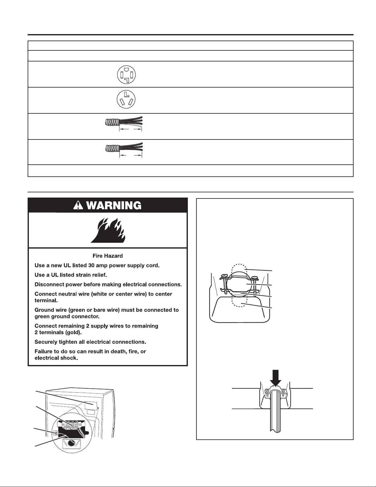
ELECTRIC DRYER ELECTRICAL CONNECTIONS
A. Strain relief tab
pointing up
B. Hole below terminal
block opening
C. Clamp section
D. Strain relief tab
pointing down
C
B
A
D
Tighten strain relief screws enough to hold the two clamp
sections together.
Power supply cord strain relief:
n Remove the screws from a 3/4" (19 mm) UL Listed
strain relief. Put the tabs of the two clamp sections into
the hole below the terminal block opening so that one
tab is pointing up and the other is pointing down, and
hold in place.
n Put power supply cord through the strain relief. Be
sure that the wire insulation on the power supply
cord is inside the strain relief. The strain relief should
have a tight t with the dryer cabinet and be in a
horizontal position. Do not further tighten strain relief
screws at this point.
Electrical Connection Options
If your location has: And you will be connecting to: Go to Section
4-wire receptacle A UL Listed, Power supply cord,
(NEMA Type 14-30R) 120/240 volt minimum, 30 amp 4-wire connection
dryer power supply cord*
3-wire receptacle A UL Listed, Power supply cord,
(NEMA type 10-30R) 120/240 volt minimum, 30 amp 3-wire connection
dryer power supply cord*
4-wire direct A fused disconnect Direct wire,
or circuit breaker box* 4-wire connection
3-wire direct A fused disconnect Direct wire,
or circuit breaker box* 3-wire connection
* If local codes do not permit the connection of a cabinet-ground conductor to the neutral wire, go to “Optional, 3-wire connection” section.
5"
(127 mm)
3½"
(89 mm)
1. Disconnect power.
2. Remove the hold-down screw and terminal block cover.
3. Install power supply cord strain relief.
B
D
C
A
A. Neutral ground wire
B. External ground
conductor screw
C. Center terminal
block screw
D. Terminal block cover
and hold-down screw
Power Supply Cord
Loading ...
Loading ...
Loading ...