This thermostat requires 24 Volt AC Power or two (2) properly installed
“AA” Alkaline batteries for proper operation. When connecting 24 Volt
AC Power the batteries may be installed as a backup.
For use only as described in this manual. Any other use
will void warranty.
1020NC
Single Stage Heat / Cool
Conventional and Heat Pump
1
Specifications
2
About Your Thermostat
3
Installation
4
System Testing
5
Setting User Options
6
Operating Your Thermostat
7
Additional Operation Features
8
Thermostat Maintenance
®
Warning
Turn off power to the heating or cooling
equipment before installation.
Attention
For installation by experienced service
technicians only.
1220NC
Up to 2 Heat / 1 Cool
Conventional and Heat Pump
Read all instructions before proceeding.
This thermostat is compatible with:
• Singlestageheat/coolconventionalandheatpumpsystems
• Conventionalsystemsupto2heat/1cool(1220NConly)
• Singlecompressorheatpumpsystemswithanauxiliaryheatstage(1220NConly)
• 250–750millivoltheatonlysystems
Electrical and control specifications:
•ElectricalRating:24VoltAC
•1ampmaximumloadperterminal
•ACPower:18–30VoltsAC
•DCPower:3.0VoltDC(2“AA”AlkalineBatteriesIncluded)
•ControlRange:45°–90°F(7°–32°C)
•TemperatureAccuracy:+/-1°F(+/-.5°C)
Terminations
•1020NC–Rc,Rh,O,B,Y1,W1,G,C
•1220NC–Rc,Rh,O,B,Y1,E/W1,G,W2,C
1
Specifications
1020NCW-100-03
Non-Programmable
Thermostats
Model number is located on back of thermostat
Detailed
Installer Guide
1
Single Stage Heat / Cool
Conventional and Heat Pump
5
Setting User Options
6
Operating Your Thermostat
7
Additional Operation Features
8
Thermostat Maintenance
For installation by experienced service
technicians only.
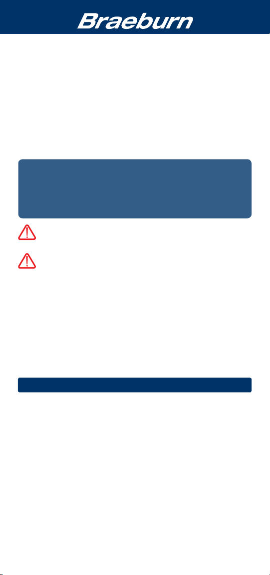
2
About Your Thermostat
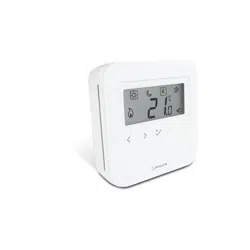
Room Temperature........... Displaysthecurrentroomtemperature
Reset Button.....................
Resetsthermostatbacktofactorydefaults
Low Battery Indicator...... Indicateswhenthebatteriesneedto
bereplaced
System Switch..................SelectsSystemPreference
Quick Reference
Instructions......................Storedinslotattopofthermostat
Fan Indicator.................... Indicateswhenthesystemfanisrunning
System Status Indicator...Displaysinformationaboutthestatusof
thesystem
Arrow Buttons.................. Usedtoincreaseordecreasesettings
Set Temperature...............Displaysthecurrentsetpointtemperature
Fan Switch........................Selectsthesystemfanmode
Battery Compartment....... Locatedinthebackofthethermostat
1
2
3
4
5
1
2
3
3
Installation
Warning
Disconnect power before beginning installation.
Thermostat Location
Installthethermostatapproximately5feet(1.5m)abovetheoorinan
areathathasagoodamountofaircirculationandmaintainsanaverage
roomtemperature.
Avoidinstallationinlocationswherethethermostatcanbeaffectedby
drafts,deadairspots,hotorcoldairducts,sunlight,appliances,concealed
pipes,chimneysandoutsidewalls.
7
5
6
8
9
6
7
8
Model number is located on back of thermostat
10
9
4
10
2
Install your new Braeburn thermostat in 5 basic steps:
1 InstalltheSub-Base
2 ProvidePower
3 ConnectYourWires
4 SetInstallerSwitches
5 AttachThermostattoSub-Base
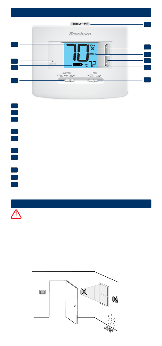
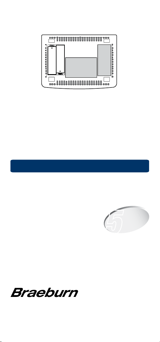
Install the Sub-Base:
•Removethesub-basefromthebodyofthethermostat.
•Mountthesub-baseasshownbelow:
1
Drill 3/16” pilot holes in
your desired location.
Use supplied anchors for
drywall or plaster.
NOTE: After sub-base installation, you may insert the quick reference card
into the slot on the top of the base.
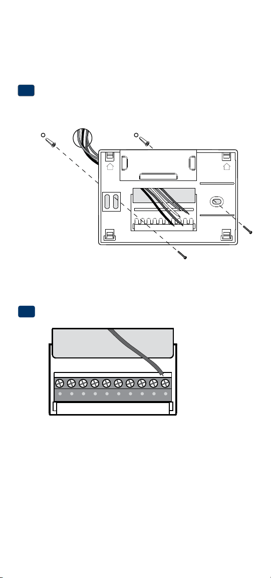
Provide Power
•For 24 Volt AC power,youmustconnectthecommonsideofthetrans-
formertotheCterminalonthethermostatsub-base.
•For primary or back-up power,insertthe2supplied“AA”typealkaline
batteriesintothebatterycompartmentlocatedintherearhousingofthe
thermostat.MakesuretopositionthePositive(+)andNegative(-)sides
ofthebatteriescorrectlywiththe+/-symbolsinthebatterycompartment.
24VAC Power
Terminal (C)
2
UP UP
C
3
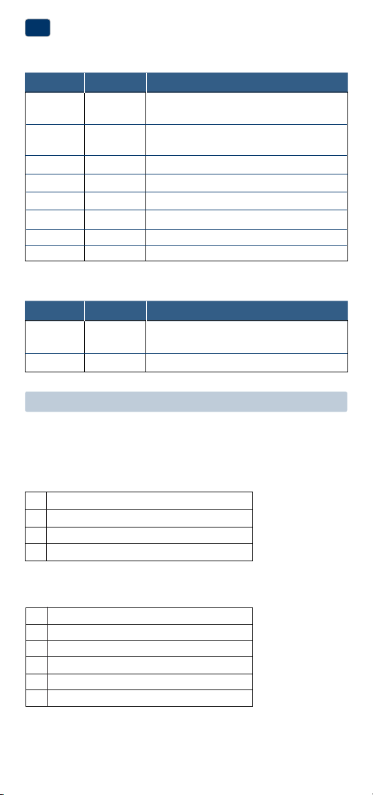
Terminal Function Description
Rc Input 24VoltACCoolingTransformer
(DualTransformerSystemsOnly)
Rh Input PowerConnection(24VoltACHeating
TransformerorMillivoltPowerSource)
O Output ReversingValve(CoolActive)
B Output ReversingValve(HeatActive)
Y1 Output 1stStageCompressor
G Output FanControl
W1 Output 1stStageConventionalHeat
C Input 24VoltACTransformerCommon
Connect Your Wires
3
Wiring Terminations
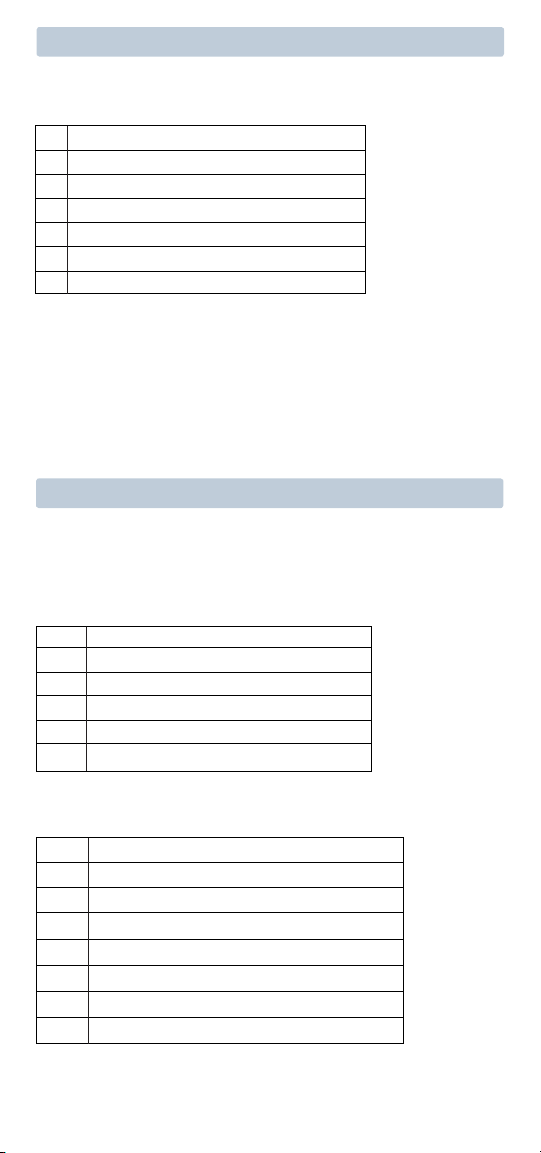
Terminal Function Description
W1/E Output (W1)1stStageConventionalHeat
(E)EmergencyHeatRelay
W2 Output 2ndStageHeat/AuxiliaryHeat
Additional Terminations (1220NC only)
1 HEAT / 1 COOL Single or Dual Transformer
Set Installer Switch to CONV
Rh
24VoltACPower(heatingtransformer)[note 2]
Rc
24VoltACPower(coolingtransformer)[note 2]
W1 HeatRelay(appearsasW1/Eon1220NC)
Y1 CompressorRelay
G FanRelay
C 24VoltACTransformerCommon[note 1, 3]
Typical Wiring Configurations
NOTE: The “Installer Switch” option will be configured in the next step.
Conventional Systems
Heat Only or Millivolt
Set Installer Switch to CONV
Rh
PowerConnection
W HeatRelay(appearsasW1/Eon1220NC)
G FanRelay[note 4]
C 24VoltACTransformerCommon[note 1]
4
NOTES - Conventional Systems
[1]Ifbatteriesareinstalledthe24VoltACcommonconnectionisoptional
[2]Removefactoryinstalledjumperfordualtransformersystems
[3]Indualtransformersystems,transformercommonmustcomefrom
coolingtransformer
[4]Ifneededforsystem
Provide disconnect and overload protection as required.
2 HEAT / 1 COOL Single or Dual Transformer (1220NC Only)
Set System Type to CONV
Rh
24VoltACPower(heatingtransformer)[note 2]
Rc
24VoltACPower(coolingtransformer)[note 2]
W1 HeatRelayStage1
W2 HeatRelayStage2
Y1 CompressorRelayStage1
G FanRelay
C 24VoltACTransformerCommon[note 1, 3]
Conventional Systems (cont.)
Typical Wiring Configurations
NOTE: The “Installer Switch” option will be configured in the next step.
Heat Pump Systems
1 HEAT / 1 COOL - No Auxiliary Heat
Set Installer Switch to HP
Rh 24VoltACPower
Rc ConnectedtoRhwithsuppliedJumperWire
O or B
ChangeoverValve [note 2]
Y1 CompressorRelay
G FanRelay
C 24VoltACTransformerCommon [note 1]
2 HEAT / 1 COOL - Including Auxiliary Heat (1220NC only)
Set Installer Switch to HP
Rh 24VoltACPower
Rc ConnectedtoRhwithsuppliedJumperWire
O or B
ChangeoverValve[note 2]
Y1
CompressorRelay(1ststageheating/cooling)
W2 AuxiliaryHeatRelay(2ndstageheating)[note 3]
E EmergencyHeatRelay [note 3]
G FanRelay
C 24VoltACTransformerCommon [note1]
(Continued)
Factory Setting
Switch Default Options Comments
5
Heat Pump Systems (cont.)
NOTES - Heat Pump Systems
[1]Ifbatteriesareinstalledthe24VoltACcommonconnectionisoptional.
[2]SelectOforcoolactiveor Bforheatactive.
[3]InstallaeldsuppliedjumperbetweentheW2 and Eterminalsif
thereisnoseparateemergencyheatrelayinstalled.
Provide disconnect and overload protection as required.
CONV/HP CONV
F/C F
HE/HG HG
Set Installer Switches
4
CONV Selectforconventionalsystems
HP Selectforheatpumpsystems
F Selectforfahrenheittemperaturescale
C Selectforcelsiustemperaturescale
HG Selectforgasheat
HE Selectforelectricheat
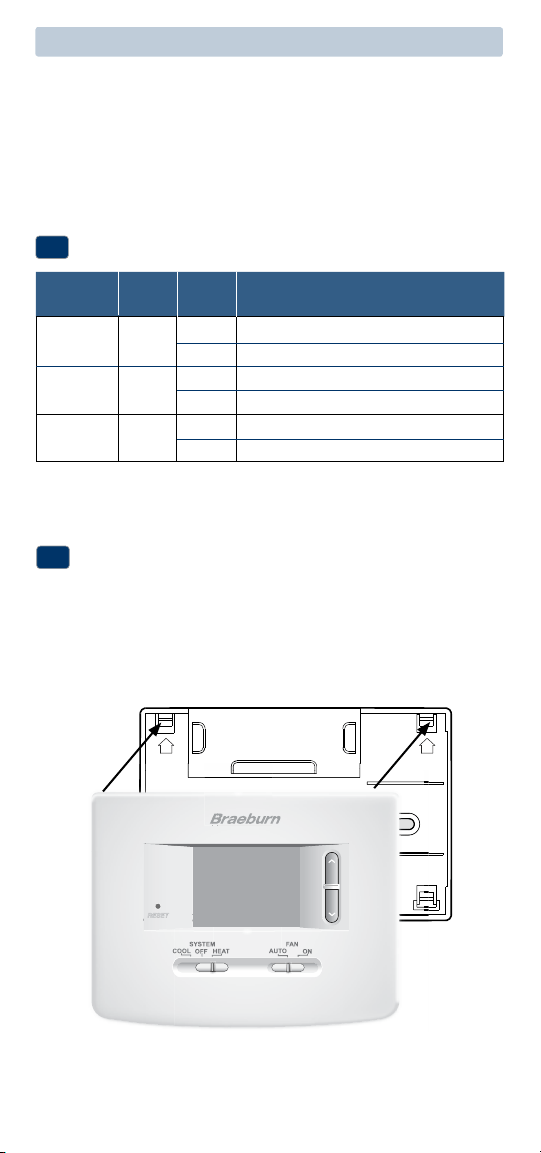
Attach Thermostat to Sub-Base
5
1.Lineupthethermostatbodywiththesub-base.
2.Carefullypushthethermostatbodyagainstthesub-baseuntilitsnaps
intoplace.
3.Insertquickreferencecardintoslotontopofthermostat.
NOTE: The reset button should be pressed after making any changes to the
installer switches.
UP UP

6
4
System Testing
Warning
Read Before Testing
• Donotshort(orjumper)acrossterminalsonthegasvalveoratthe
heatingorcoolingsystemcontrolboardtotestthethermostatinstalla-
tion.Thiscoulddamagethethermostatandvoidthewarranty.
• DonotselecttheCOOLmodeofoperationiftheoutsidetemperature
isbelow50ºF(10ºC).Thiscouldpossiblydamagethecontrolledcool-
ingsystemandmaycausepersonalinjury.
• Thisthermostatincludesanautomaticcompressorprotectionfeatureto
avoidpotentialdamagetothecompressorfromshortcycling.When
testingthesystem,makesuretotakethisdelayintoaccount.
NOTE: The compressor delay can be bypassed by pressing the reset button
on the front of the thermostat. All user settings will be returned to factory
default.
1 MovetheSYSTEMswitchtoHEATmode.
2 Presstoraisethesettemperatureaminimumof3degreesabove
thecurrentroomtemperature.Thesystemshouldstartwithinafew
seconds.Withagasheatingsystem,thefanmaynotstartrightaway.
3 MovetheSYSTEMswitchtotheOFFmode.Allowtheheatingsystemto
fullyshutdown.
4 MovetheSYSTEMswitchtotheCOOLmode.
5 Presstolowerthesettemperatureaminimumof3degreesbelow
thecurrentroomtemperature.Thesystemshouldstartwithinafew
seconds(unlesscompressorshortcycleprotectionisactive–See
noteabove).
6 MovetheSYSTEMswitchtotheOFFmode.Allowthecoolingsystemto
fullyshutdown.
7 MovetheFANswitchtotheONmode.Thesystemfanshouldstart
withinafewseconds.
8 MovetheFANswitchtotheAUTOmode.Allowthesystemfanto
turnoff.
5
Setting User Options
Advanced User Options
Useroptionsallowyoutocustomizesomeofyourthermostatsfeatures.
Mostuserswillnotneedtomakeanychangestothesettingsinthissection.
To access the User Options menu, hold down both the and buttons
for approximately 3 seconds until the screen changes and displays
the first User Option.
PresstheorbuttontochangethesettingforthedisplayedUserOption.
Afteryouhavemadeyourdesiredsetting,pressandtogetherto
advancetothenextUserOption.
Thethermostatwillreturntonormalmodeafteryourlastuseroptionis
madeorafternokeyshavebeenpressedfor15seconds.
7
User Factory Setting
No. Options Default Options Comments
1 1ststage
0.5
0.5, 1.0
Selecta1ststagetemperature
differential
or 2.0 differentialof.5˚,1˚or2˚F(.2˚,.5˚
or1˚C)
2 2ndstage
2.0
1.0, 2.0,
Selecta2ndstagetemperature
differential
3.0, 4.0
, differentialof1˚,2˚,3˚,4˚,5˚or6˚F
(1220NCOnly
)
5.0 or 6.0
(.5˚,1˚,1.5˚,2˚,2.5˚or3˚C)
Table of User Options
Detailed Explanation of User Options:
Temperature Differential
(User Option 1 and 2)
Thedifferentialsettingisthetemperaturecontrolrangethatyourthermostat
willprovide.Thesmallerthesetting,thetighteryourrangeoftemperature
controlandcomfortwillbe.The2ndstagedifferentialisonlyforsystems
withasecondstageofheating(auxiliaryheat).
6
Operating Your Thermostat
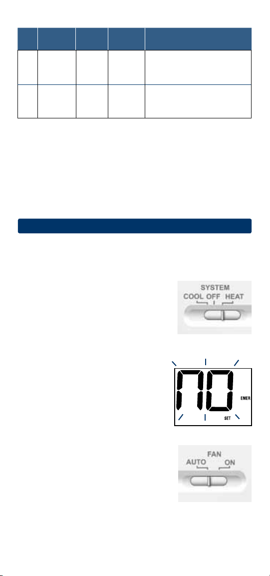
Setting the System Control Mode
TheSystemControlhasseveralmodesofoperationthatcanbeselectedby
movingtheSYSTEMswitchtotheappropriateposition.
COOL Onlyyourcoolingsystemwilloperate
OFF Heatingandcoolingsystemsareoff.
HEAT Onlyyourheatingsystemwilloperate.
Additional Switch Position (Model 1220NC Only):
EMER Operatesabackupheatsource(EmergencyHeat)forheatpump
systemsonly.
NOTE:
If your model 1220NC was configured for a
conventional system (CONV) then you will not have
the EMER (emergency heat) option and “NO EMER
SET” will flash in the display if EMER is selected
with the system switch.
Setting the Fan Control Mode
The Fan Control has 2 modes of operation – AUTO
and ON. The mode can be selected by moving the
FAN switch to the appropriate position.
AUTO Thesystemfanwillrunonlywhenyour
heatingorcoolingsystemisrunning.
ON Thesystemfanstayson.
8
Detailed Explanation of User Options:
Temperature Differential
(User Option 1 and 2)
Thedifferentialsettingisthetemperaturecontrolrangethatyourthermostat
willprovide.Thesmallerthesetting,thetighteryourrangeoftemperature
controlandcomfortwillbe.The2ndstagedifferentialisonlyforsystems
withasecondstageofheating(auxiliaryheat).
Temperature Adjustment
Presstheorbuttontoadjustthecurrentsetpointtemperature.
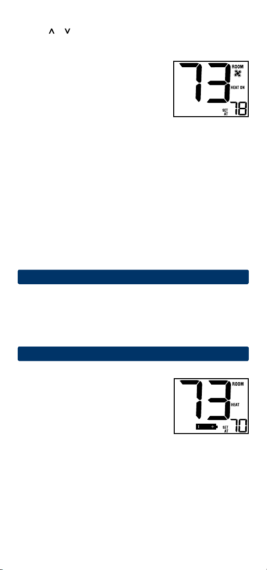
Status Indicators
Statusindicatorsappearinthedisplaytolet
youknowifyoursystemisheating,cooling
oroff.
HEAT ON
Indicatesyourheatingsystemisrunning.
COOL ON
Indicatesyourcoolingsystemisrunning.
Additional Status Indicators (Model 1220NC Only):
AUX Indicatesthattheauxiliarystageofheatingisrunning
(Multi-StageSystemsonly).
EMER Indicatesthattheemergencyheatingsystemisrunning
(HeatPumpSystemsonly).
Resetting the Thermostat
Thisthermostatprovidesyouwitharesetbuttonthatwilleraseallofyour
usersettings.
Toresetthethermostat,useasmallobjectsuchasatoothpickorpaper-
clipandgentlypressthebuttonlocatedinsidethesmallholeonthefrontof
thethermostathousinglabeled“reset”.
7
Additional Operation Features
Compressor Protection
Thisthermostatincludesanautomaticcompressorprotectiondelayto
avoidpotentialdamagetoyoursystemfromshortcycling.Thisfeature
activatesashortdelayafterturningoffthesystemcompressor.
8
Thermostat Maintenance
Changing the Batteries
Dependingonyourparticularinstallation,this
thermostatmaybeequippedwithtwo(2)“AA”
typealkalinebatteries.
If batteries are installed and they become low,
a low battery indicator will appear in the display.
You
shouldchangeyourbatteriesimmediately
whenyouseethelowbatterysignalbyfollowing
theseinstructions.
1.Removethermostatbodybygentlypullingitfrombase.
2.Removeoldbatteriesandreplacewithnewbatteries.
3.Makesuretocorrectlypositionthe(+)and(-)symbols.
4.Gentlypushthermostatbodybackontobase.
NOTE: We recommend replacing the thermostat batteries annually or if the
thermostat will be unattended for an extended period of time.
Thermostat Cleaning
Neversprayanyliquiddirectlyonthethermostat.Usingasoftdampcloth
wipetheouterbodyofthethermostat.Neveruseanyabrasivecleansersto
cleanyourthermostat.
For troubleshooting tips, visit braeburnonline.com.
BraeburnSystemsLLC
2215CornellAvenue•Montgomery,IL60538
TechnicalAssistance:www.braeburnonline.com
Callustoll-free:866-268-5599(U.S.)
630-844-1968(OutsidetheU.S.)
©2013BraeburnSystemsLLC•AllRightsReserved•MadeinChina.
®
Store this manual for future reference.
1020NCW-100-03
Limited Warranty
Wheninstalledbyaprofessionalcontractor,thisproductisbackedbya5year
limitedwarranty.Limitationsapply.Forlimitations,termsandconditions,you
mayobtainafullcopyofthiswarranty:
·Visitusonline:www.braeburnonline.com/warranty
·Phoneus:866.268.5599
·Writeus:BraeburnSystemsLLC
2215CornellAvenue
Montgomery,IL60538
+
+
5
YEAR
WARRANT Y
LIMITED