Dig
ital Thermostats
Model: AHTR3024
INST
ALLER MANUAL
SAL
US North America is a member of the Computime Group
M
aintaining a policy of continuous product development SALUS Controls plc reserve the right to
change specification, design and materials of products listed in this brochure without prior notice.
Issue Date: Oct 2016
00191
F
or PDF Installation guide please go to:
www.salusna.com
W
arranty
SAL
US NA warrants that this product (AHTR3024) will be free from any
defect in materials or workmanship, and shall perform in accordance with its
specification, for a period of five years from the date of installation. SALUS NA
sole liability for breach of this warranty will be (at its option) to repair or replace
the defective product.
Customer Name: ....................................................................................................................................................
Customer Address: ...............................................................................................................................................
............................................................................................................................................................................................
....................................................................................... Post Code: ..........................................................................
Tel No: .................................................................... Email: .......................................................................................
Engineers Company: ...........................................................................................................................................
Tel No: ...................................................................... Email: ....................................................................................
Instalation Date: .....................................................................................................................................................
Engineers Name: ...................................................................................................................................................
Engineers Signature: ...........................................................................................................................................
14. T
echnical Data
M
odel: AHTR3024
V
oltage
24
VAC, +/-10 %, 50/60 Hz
Operating per
formance
24
V, 18 W
T
emperature setback
A
djustable
T
emperature range
5°C – 35°C (41
º
F
- 95º
F)
Span
+/-0,5°C (32,9ºF
) OR +/-0,25°C (32,45ºF)
St
orage temperature
-20°C t
o +60°C (-4
º
F t
o +140
º
F)
Ambient t
emperature
0 °C up t
o 45 °C(32
º
F up t
o 113
º
F)
D
egree of protection
IP 30
C
onformity according to
FC
C and IC
Housing
material
PC, V2
C
olor
RAL 9010 pur
e white
C
onnection
S
crew terminal
W
eight
125 g net / 170 g g
ross (4.40oz/5.99oz)
P
uls-wide-modulation (PWM)
Y
es
P
rofile Modes
3 ( Sun, M
oon, Automatic)
Heating and C
ooling
Y
es, automatically Change Over
on the
Wiring Centre
P
arameter adjustment
Y
es, in Installer Mode
Dimensions
85mm*85mm*25mm( 3.34in*3.34in*0.98in)
8. S
etting the Thermostat
9. S
etting the Thermostat
Not
e: The d20 will help you to reduce the power outlet on the thermostat.
S
etting the hysteresis
You can set the hysteresis by entering the Installer Mode, accessing d01 and after that
selecting the desired value ( PWM / 0.5°C or 32.9º
F
/ 1.0°C or 33.8º
F
). I
f your device
controls the UFH we recommend to use the PWM algorithm.
Heating and Cooling Selection
Manually
This mode will be indicated by the flashing icons
Press or to change between modes.
Auto
The CO terminal needs to be connected
using the same phase as the power supply.
After that the heating and cooling functions will be done automatically In Installer
Mode, d18 has to be set on 1 (default is 0), when CO wire is connected.
10. S
etting the Thermostat
C
ooling blocked
When the thermostat is set on Cooling Disabled (d19-->1) it will block the cooling
function for single rooms until the device receives the heating command. During the
periods of Cooling Blocked no special indicator will be displayed on the LCD screen.
Cooling mode indicator will also be turned off.
Protection
When room temperature is over the limit of 36°C(96.8ºF
), all heating outputs will be
tur
ned off regardless of the control pattern and delay timers. When room temperature
is under the limit of 4°C(39.2º
F), all cooling outputs will be tur
ned off regardless of the
control pattern and delay timers.
Device
No
d01
d02
d05
d07
d08
d12
d13
d18
d19
d20
0
0
0
0
1
1
1
2
1
0
5.0 - 17.0 ºC
41- 95
º
F
5.0 - 40.0 ºC
2
1
-3,0 ºC t
o +3,0 ºC
-26,6
º
F
t
o +37,4
º
F
0
0
0
0
0.0ºC / 32
º
F
2
1
P
WM
No Connection
Cooling Allowed
1 to 5 actuators loading
Connection
Cooling Disabled
O
ffset room temp measuring
error (in 0,5 ºC /
32,9 ºF
)
R
oom temp offset
Heating Control
Heating/Cooling Mode
Cooling Blocked
Selecting the number
of actuators
Cooling Control
Valve Protection
F
rost Setpoint
M
ax. Heating Setpoint
Min. Cooling Setpoint
D
efault
Value
Function
V
alves
D
enition
Disable
Enable
On-Off: 33.8 ºC (+_32,9
º
F
)
On-
Off: 1,0 ºC (+_0,5 ºC)
11. F
actory Reset
12. Heating/C
ooling Mode
13. T
emperature Offset
(
TemperatureCalibration)
P
ress the indicated keys
together for 3 seconds.
S
elect P47 if you want to
reset to factory settings.
P
ress to confirm
P
ress to confirm
Not
e: In order to
quickly reach 47 you
can hold down
key. The display will
fast forward in steps
of 5.
Heating M
ode
C
ooling Mode
T
emperature Mode Heating Cooling
Sunny 20.0 °C / 68.0 °F 20.0 °C / 68.0 °F
Moon 17.0 °C / 62.6 °F 26.0 °C / 78.8 °F
Frost (heat system)
5.0 °C / 41 °F --.-
T
he Temperature Offset can be set at any value between
-3°C(26.6
ºF) and +3°C(37.4ºF
)
. P
ress OK to confirm.
L
ong press in order to
enter the Settings Mode.
P
ress or in order to
set the Temperature Offset.
www.salusna.com
SALUS
NORTH AMERICA,
850 MAIN STREET, REDWOOD CITY, CA 94063
EMAIL: SALES@SALUSNA.COM
TEL:
+1-650-360-1725
d00
S
elect
º
C/
º
F
0
1
º
C
º
F
0
5.0ºC / 41
º
F
35ºC / 95
º
F
5.0ºC / 41
º
F
41 - 104 º
F
5.0 - 35.0 ºC
41 - 62.6 º
F
F F
)
On-
Off: 1,0 ºC (+_0,5 ºC)
On-
Off: 0,5 ºC (+_0,25 ºC)
On-Off: 32,9 º
F
(+_32,45 º
F
)
On-
Off: 33,8 ºC (+_32,9
º
F
)
On-
Off: 0,5 ºC (+_0,25 ºC)
On-Off: 32,9 º
(+_32,45 º
NSB Mode depends on the NSB wired connection.
0V=NSB OFF
24V=NSB ON
This function will be activated only when the device is running in Auto Mode.
If the thermostat receives a NSB signal then it will switch to - . If the NSB is turned
off, the unit will function in and . You can manually set the thermostat on NSB
by moving the box on the icon.
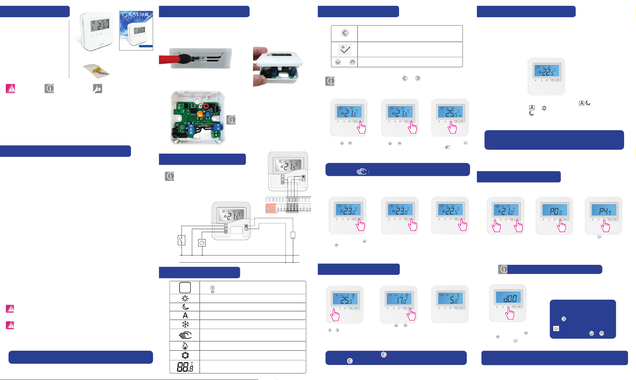
4. Button Functions
Mode selection.
Long press to return home without saving.
OK key. Short press to confirm selection.
Long press to save and return home.
Long press to enter Temperature offset Heat/Cool.
Decrease or increase Setpoint Temperature.
In Auto Mode by tapping
the or key you
can view the Setpoint
Temperature.
In Auto Mode by holding
the or key you will
access Manual Override
Mode.
After selecting the
temperature press
and the will appear.
Note: In Auto Mode the change in Manual Override Mode is temporary. This is
indicated by the icon. When used as a stand alone, the change is permanent.
In Sunny/ Moon/ Frost
Mode by tapping the
or key you will access
Manual Override Mode.
In Sunny/ Moon/ Frost
Mode the change will be
permanent.
When Auto Mode is
selected again the
permanent override
will end.
5. Frost Protection
Move the box by tapping
or on the Frost
Mode Indicator The device
will enter in Frost Mode.
In Frost Mode you can
select a temperature
between 5°-17°C or 41-62.6°F.
Press the or key to
set the temperature.
Note: During the set-up, press at any time to return to the previous screen or
long press to return to Home display.
Product Compliance & Safety Information
Safety Information
Use in compliance with safety regulations. The unit is to be used for the control of room temperature
inside the house.
Installation
This accessory must be fitted by a competent person, and installation must comply with the guidance,
standards and regulations applicable to the city, country or state where the product is installed. Failure
to comply with the relevant standards could lead to prosecution.
Note: All electrical installation work should be carried out by a suitable
qualified electrician or other competent person.
Product Description
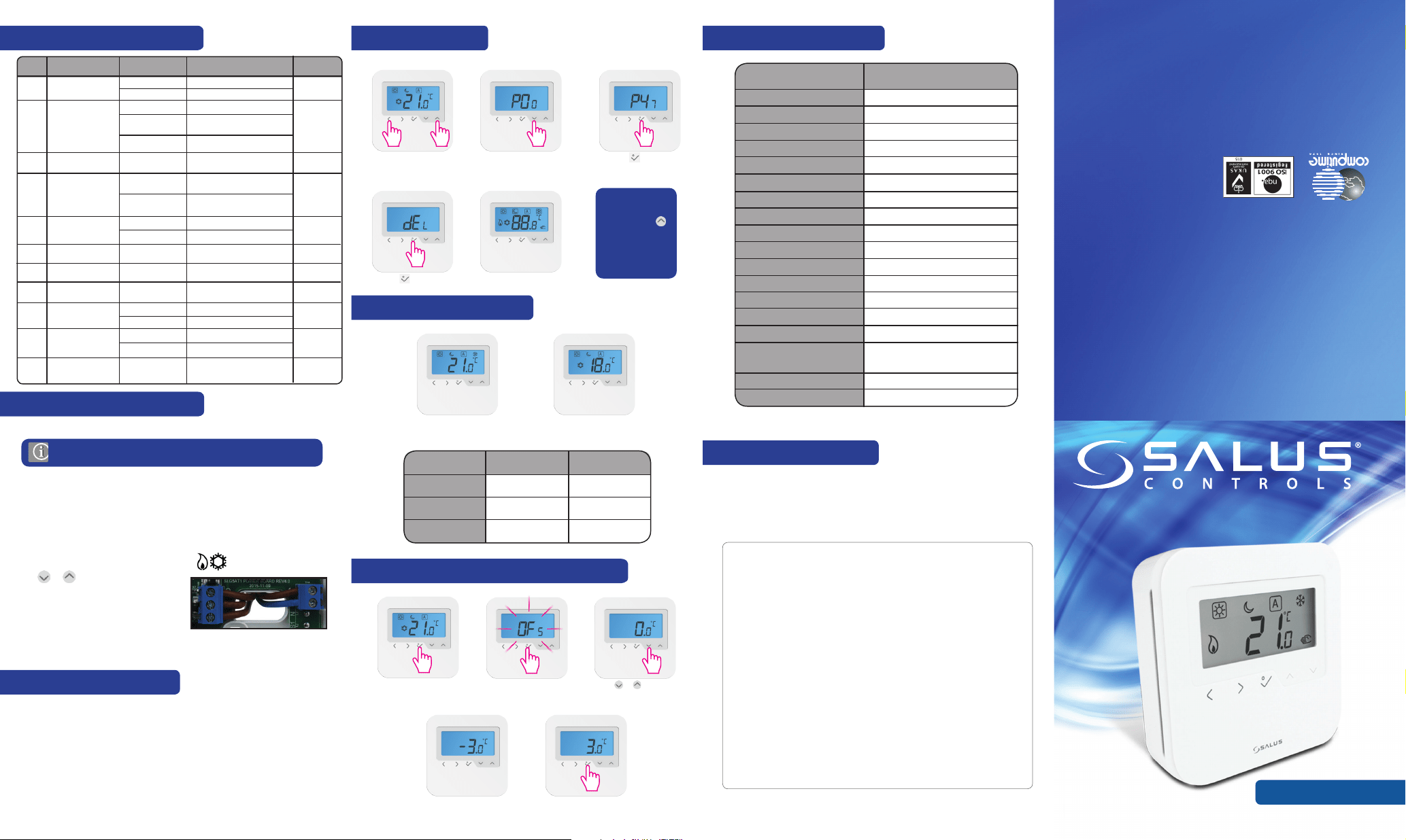
Thank you for purchasing the SALUS AHTR3024 Thermostat. This thermostat is a device that
lets you customise the heating and cooling of your home as needed.
The AHTR3024 device from SALUS Controls is a stylish and accurate digital room
thermostat that is fitted with a large easy to read LCD screen and one touch
buttons. You can now simply adjust your home temperature as desired in order to create a
comfortable home environment.
We hope you enjoy our product.
Contents of the box
Manual Contents:
Box Contents
Introduction
Product Compliance and
Safety Information
Installation
User Interface
Status/LED indication
Installers notes
Warranty
Icons used in this manual:
Safety Important info Your benefit
Fixing Screws
1 x Installer Manual
Digital Thermostats
Model: AHTR3024
INSTALLER MANUAL
SALUS Controls is a member of the Computime Group
Maintaining a policy of continuous product development SALUS Controls plc reserve the right to
change specification, design and materials of products listed in this brochure without prior notice.
Issue Date: Dec 2015
00191
For PDF Installation guide please go to:
www.salus-manuals.com
Warranty
SALUS Controls warrants that this product (AHTR3024) will be free from any
defect in materials or workmanship, and shall perform in accordance with its
specification, for a period of five years from the date of installation. SALUS Controls
sole liability for breach of this warranty will be (at its option) to repair or replace
the defective product.
Customer Name: ....................................................................................................................................................
Customer Address: ...............................................................................................................................................
............................................................................................................................................................................................
....................................................................................... Post Code: ..........................................................................
Tel No: .................................................................... Email: .......................................................................................
Engineers Company: ...........................................................................................................................................
Tel No: ...................................................................... Email: ....................................................................................
Instalation Date: .....................................................................................................................................................
Engineers Name: ...................................................................................................................................................
Engineers Signature: ...........................................................................................................................................
14. Technische Daten
Model: AHTR3024
Voltage 24 VAC, +-10 %, 50/60 Hz
Operating performance 24 V: 1,8 W
Temperature setback Adjustable
Temperature range 5°C – 35°C
Span +/-0,5C OR +/-0,25C
Storage temperature -20°C to +60°C
Ambient temperature 0 °C up to 45 °C
Degree of protection IP 30
Conformity according to FCC and IC
Housing material PC, V2
Color RAL 9010 pure white
Connection Screw terminal
Weight 125 g net / 170 g gross
Puls-wide-modulation (PWM) Yes
Profile Modes 3 ( Sun, Moon, Automatic)
Heating and Cooling Yes, automatically Change Over
on the Wiring Centre
Parameter adjustment Yes, in Installer Mode
Dimensions 85mm*85mm*25mm
8. Setting the Thermostat
9. Setting the Thermostat
Note: The d20 will help you to reduce the power outlet on the thermostat.
Setting the hysteresis
You can set the hysteresis by entering the Installer Mode, accessing d01 and after that
selecting the desired value ( PWM / 0.5°C / 1.0°C ). If your device controls the UFH we
recommend to use the PWM algorithm.
Heating and Cooling Selection
Manually
This mode will be indicated by the flashing icons
Press or to change between modes.
Auto
The CO terminal needs to be connected
using the same phase as the power supply.
After that the heating and cooling functions will be done automatically In Installer
Mode, d18 has to be set on 1 (default is 0), when CO wire is connected.
10. Setting the Thermostat
Cooling blocked
When the thermostat is set on Cooling Disabled (d19-->1) it will block the cooling
function for single rooms until the device receives the heating command. During the
periods of Cooling Blocked no special indicator will be displayed on the LCD screen.
Cooling mode indicator will also be turned off.
Protection
When room temperature is over the limit of 36°C, all heating outputs will be turned off
regardless of the control pattern and delay timers. When room temperature is under
the limit of 4°C, all cooling outputs will be turned off regardless of the control pattern
and delay timers.
Device
No
d01
d02
d05
d07
d08
d12
d13
d18
d19
d20
0
0
0
0
1
1
1
2
1
0
5.0-17.0ºC
5.0-35.0ºC
5.0-40.0ºC
2
1
-3,0 ºC to
+3,0 ºC
0
0
0
0
0.0ºC
5.0ºC
35.0ºC
5.0ºC
2
1
PWM
No Connection
Cooling Allowed
1 to 5 actuators loading
Connection
Cooling Disabled
Offset room temp
measuring error (in 0,5 ºC)
Room temp offset
Heating Control
Heating/Cooling Mode
Cooling Blocked
Selecting the number
of actuators
Cooling Control
Valve Protection
Frost Setpoint
Max. Heating Setpoint
Min. Cooling Setpoint
Default
Value
Function
Valves
Denition
On-Off: 0,5 ºC (+_0,25 ºC)
On-Off: 0,5 ºC (+_0,25 ºC)
Disable
Enable
On-Off: 0,5 ºC (+_0,5 ºC)
On-Off: 0,5 ºC (+_0,5 ºC)
11. Factory Reset
12. Heating/Cooling Mode
13. Temperature Offset (TemperatureCalibration)
Press the indicated keys
together for 3 seconds.
Select P47 if you want to
reset to factory settings.
Press to confirm
Press to confirm
Note: In order to
quickly reach 47 you
can hold down
key. The display will
fast forward in steps
of 5.
Heating Mode Cooling Mode
Temperature Mode Heating Cooling
Sunny 20.0ºC 20.0ºC
Moon 17.0ºC 26.0ºC
Frost (heat system)
5ºC --.-
The Temperature Offset can be set at any value between
-3°C and +3°C. Press OK to confirm.
Long press in order to
enter the Settings Mode.
Press or in order to
set the Temperature Offset.
www.salusna.com
SALUS NORTH AMERICA,
850 MAIN STREET, REDWOOD CITY, CA 94063
EMAIL: SALES@SALUSNA.COM
TEL:
+1-650-360-1725
AHTR3024 Thermostat
Gently remove front housing and make the
wiring connections.
2. Terminal Connection
N
N
L
CO
L
ACTUATOR
E.G.
HEAT
PUMP
EXTERNAL
CLOCK
24VAC
50Hz
1. Mounting the Thermostat
N
CO
L
Note: You can wire the thermostat directly to the
AKL08 wiring centre or to an actuator
(purchased separatly).
3. Thermostat Icons
BOX means to select mode.
e.g. means Hi temp is selected
means the Hi temp is not selected.
Sunny: Hi comfortable temperature
Moon: Low comfortable temperature
Indicates AUTO ON or AUTO OFF
Frost Protection Indicator:
Frost protection is active, not available in cooling mode.
Heat Mode indicator: Indicates heating is running
Cood Mode indicator:
The icon is flashing when cooling mode active
Temperature indicator
• Display the room temperature
• Display the set temp
Temporary override indicator: If the set temperature is changed
when in program mode, the hand will appear until the next
programs starting time.
OR
You can change the Modes by tapping or and position the box on
the desired one.
Note: The NSB function will be available only when you also have another device
that can send a NSB signal (AHTR3024 thermostat, external clock, NSB switch or
another clock thermostat).
6. Night Setback Function (NSB)
7. Installer Mode
Select P49 if you want to
enter Installer Mode.
Press to confirm.
You have reached the
Installer Mode. Select
your options by using
or and then confirm
by pressing .
Note: This function allows you to
customise your thermostat as you
desire. To select the device level use
to jump to the next one d0 > d1 >
d2 > d5. On the desired level press
then you can choose your
preferences by using or .
Press the indicated keys
together for
3 seconds.
Note: LCD backlight is activated by pressing any key.
Wall mounting
For wall mounting, mark the correct
possition on the wall and mount the
rear case to the wall.
Install the AHTR3024 digital room thermostat at roughly 1.5m or 4.92ft above floor level.
It should be mounted in a location where the thermostat is easily accessible and away
from direct sunlight. You can mount the thermostat directly on the wall or you can install
it on top of a wall-box.
FCC Statement
This equipment has been tested and found to comply with the limits for a Class
B digital device, pursuant to Part 15 of the FCC Rules. These limits are designed
to provide reasonable protection against harmful interference in a residential
installation. This equipment generates uses and can radiate radio frequency
energy and, if not installed and used in accordance with the instructions,
may cause harmful interference to radio communications. However, there is
no guarantee that interference will not occur in a particular installation. If this
equipment does cause harmful interference to radio or television reception,
which can be determined by turning the equipment off and on, the user is
encouraged to try to correct the interference by one or more of the following
measures:
• Reorient or relocate the receiving antenna.
• Increase the separation between the equipment and receiver.
• Connect the equipment into an outlet on a circuit different from that to which
the receiver is connected.
• Consult the dealer or an experienced radio/TV technician for help.
Changes or modifications not expressly approved by the party responsible for
compliance could void the user’s authority to operate the equipment.
This device complies with part 15 of the FCC Rules. Operation is subject to the
following two conditions: (1) This device may not cause harmful interference,
and (2) this device must accept any interference received, including
interference that may cause undesired operation.
This Class B digital apparatus complies with Canadian ICES-003.
Cet appareil numérique de la classe B est conforme à la norme NMB-003 du
Canada.
H
H
H
H
N
CO
L
L
N
CO
L
H
N
CO
L
N
CO
L
SH
N
CO
L
H
H
Note: For changing the temperature display from ºC to ºF, go to Installer Mode Menu
and change d00 to 1.