SPECIFICATIONS ..............................2
INSTALLATION INSTRUCTIONS
WIRING ...........................................3
INSTALLER MENU ........................4
TEST EQUIPMENT ......................... 6
USING THE THERMOSTAT
OVERVIEW .....................................7
TROUBLESHOOTING .........................8
RESETTING .................................... 9
FCC STATEMENT ............................10
THERMOSTAT
Hardwired, 2 Fan Speeds
OWNER’S MANUAL AND
INSTALLATION INSTRUCTIONS
RAK149F2A
49-5000769 Rev. 1 11-23
2 49-5000769 Rev. 1
SPECIFICATIONS
MERCURY NOTICE: This product does not contain mercury.
However, this product may replace a product that contains
mercury. Mercury and products containing mercury must not be
discarded in household trash. Refer to thermostat-recycle.org
for information on disposing of products containing mercury.
Electrical Rating:
Input-Hardwire 20 to 30 VAC, NEC Class II, 50/60 Hz
Terminal Load 1.5 A per terminal, 2.5A maximum all
terminals combined
Setpoint Range 60° to 85° F (16° to 29° C)
Rated Differentials
(@ 6°F/ Hr):
Fast Med Slow
Heat Pump (Heating) 0.9ºF 1.2ºF 1.7ºF
Heat Pump (Cooling) 0.9ºF 1.2ºF 1.7ºF
Auxiliary Heat 0.5ºF 0.75ºF 1.9ºF
Operating Ambient 32°F to +105°F (0° to +41°C)
Display Temperature
Range
32°F to +99°F (0 to 37°C)
Operating Humidity. 90% non-condensing maximum
Shipping Temperature
Range
-20°F to + 150°F (-29° to +65°C)
Thermostat Dimensions 3-3/4” H x 6” W x 1-1/8” D
Thermostat Applications Maximum Stages Heat/ Cool
Single Stage Cooling, One or Two
Stage Heating
NOTE: Two stage heating = 1st
stage heat pump and 2nd stage
resistance heat
2/1
49-5000769 Rev. 1 3
INSTALLATION INSTRUCTIONS
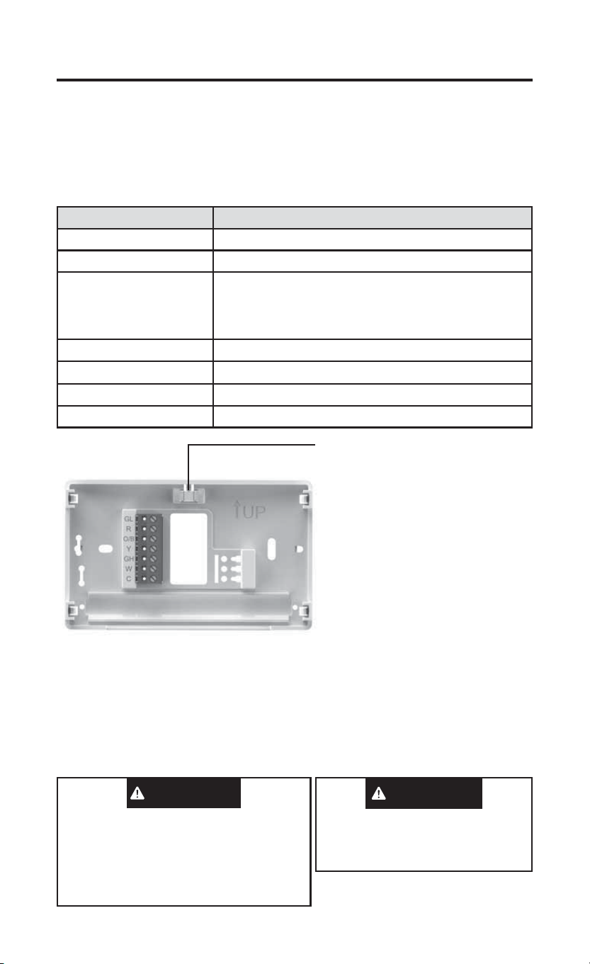
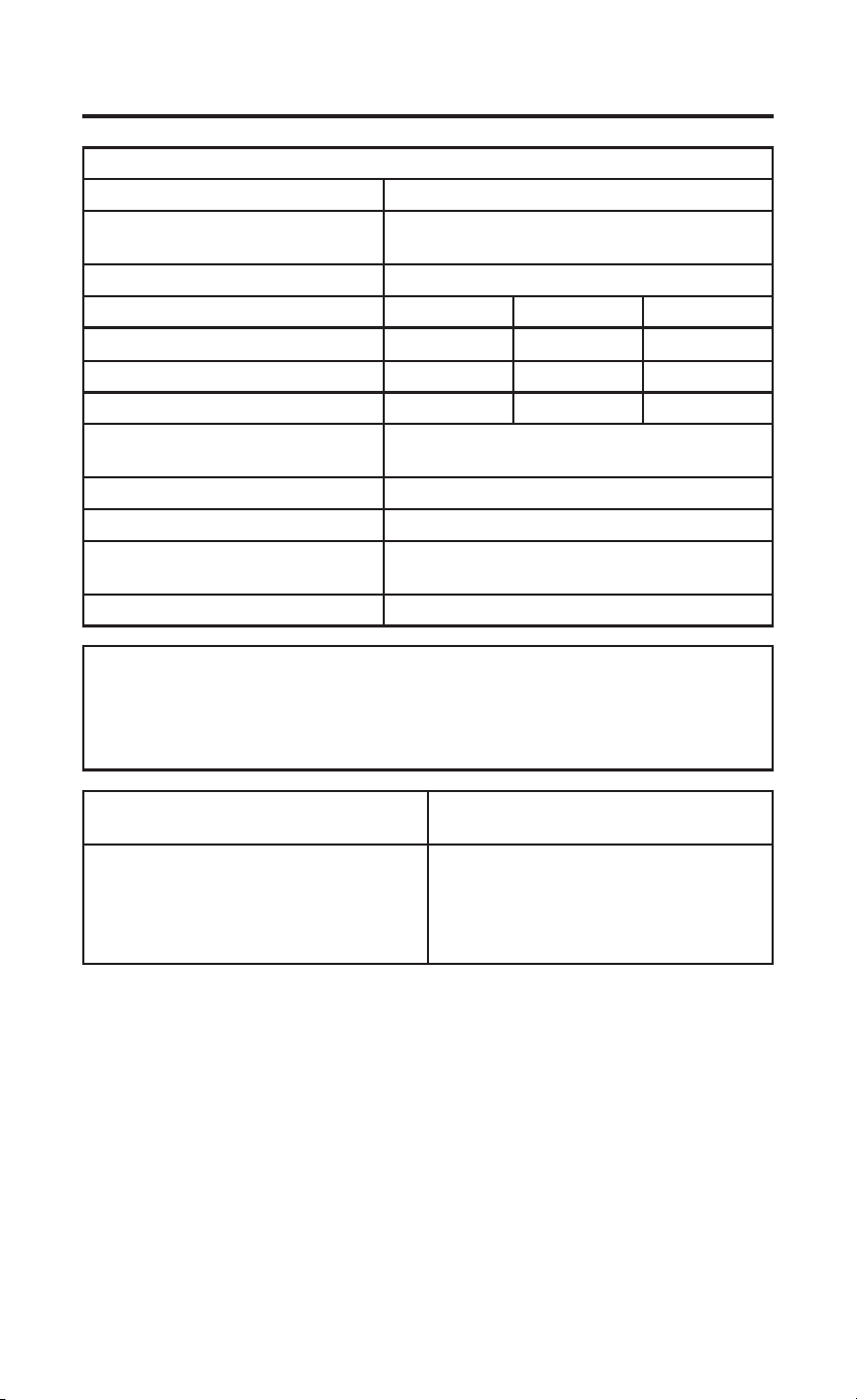
WIRING
Refer to equipment manufacturer’s instructions for specific system wiring
information. After wiring, see INSTALLER MENU for proper thermostat
configuration. Wiring table shown are for typical systems and describe the
thermostat terminal functions.
Terminal Designations Terminal Function
GL Low Speed Fan Relay
R Power (24V)
O/B Changeover Terminal-Energized in Cool (O) or Heat
(B) for Heat Pump
Note: All Zoneline/Hotpoint applications are B type
heat pump.
Y Heat and Cool Mode 1st Stage Compressor
GH High Speed Fan Relay
W Heat Mode – 2nd Stage Heat (Electric)
C Common wire for 24V
Precautions
• Do not exceed the specification ratings.
• All wiring must conform to local and national electrical codes and
ordinances.
• This control is a precision instrument, and should be handled carefully.
Rough handing or distorting components could cause the control to
malfunction.
Leveling Thermostat
Leveling is for appearance only and
will not affect thermostat operation.
To prevent electrical shock and/or
equipment damage, disconnect electrical
power to system, at main fuse or circuit
breaker box,until installation is complete.
CAUTION
Do not use on circuits exceeding specified
voltage. Higher voltage will damage control and
could cause shock or fire hazard.
Do not short out terminals on primary control
to test. Short or incorrect wiring will burn out
thermostat and could cause personal injury and/
or property damage.
WARNING

4 49-5000769 Rev. 1
WIRING (cont)
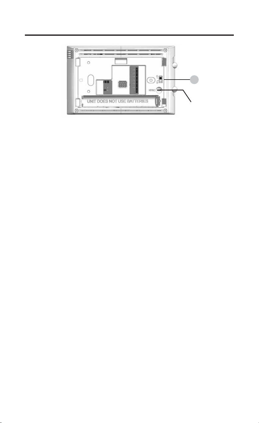
Instructions: To convert the system from PTHP to PTAC, change
menu item #20 from default HP to AC. Additionally, if you are using this
thermostat on a Hotpoint PTAC (non-heat pump), you will need to cut the
jumper wire located on the back of the thermostat.
Note: Menu item #32 will not be displayed in AC mode.
1.) O/B Terminal Switch
The O/B switch on this thermostat is factory set to the B position. This will
accommodate heat pump applications, which require the changeover relay
to be energized in Heat. If the heat pump being installed requires an O
terminal to energize the changeover relay in Cool, the O/B switch must be
moved to the O position.
INSTALLER MENU
To access the INSTALLER’S MENU, set the system switch to the OFF
position and then press and hold the temperature Ÿ and ź buttons for 3
seconds. The display will show item 20 in the table. Use the temperature
ŸDQGźEXWWRQVE\SUHVVLQJWKHPVLPXOWDQHRXVO\WRQDYLJDWHWKURXJK
PHQXLWHPV3UHVVŸRUźWRFKDQJHDPHQXVHWWLQJ7RH[LWWKH,QVWDOOHU¶V
Menu at any time, move the system switch to Heat or Cool.
INSTALLATION INSTRUCTIONS
1
Jumper
Wire
49-5000769 Rev. 1 5
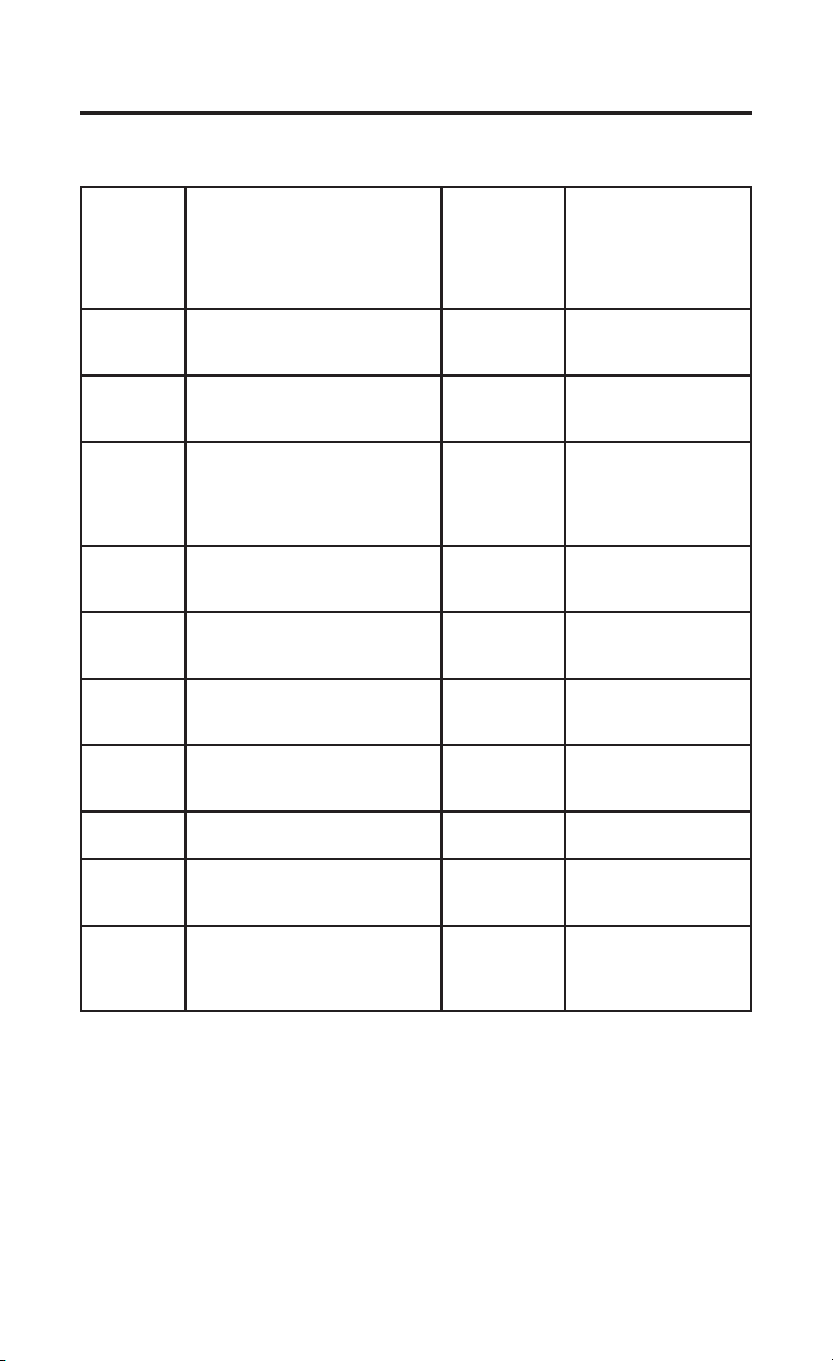
INSTALLER MENU (cont)
INSTALLATION INSTRUCTIONS
Installer’s
Menu #
(Hold Menu
3 Seconds)
Description Default
Setting
(flashing icons)
Settings
3UHVVŸRUź
20
Algorithm – AC or HP (If HP
is selected, item #32 will be
displayed)
HP HP – Heat Pump or
AC – Air Cond.
30 CR
Heat Cycle Rate (how often the
heat will turn on)
SLO SLO – slow
MEd – medium
FAS – fast
32 CR
Aux Cycle Rate (how often the
auxiliary heat will turn on)
Note: Available if HP is selected
on item #20
SLO SLO – slow
MEd – medium
FAS – fast
35 CR
Cool Cycle Rate (how often the
cooling will turn on)
SLO SLO – slow
MEd – medium
FAS – fast
50 CL
Compressor Lockout (protects
the compressor from short
cycling)
OFF On – 5 minute delay
OFF – no delay
65
Maximum Heat Limit (maximum
set point for heat mode)
85°F 45°F to 99°F
66
Minimum Cool Limit (minimum
set point for cool mode)
60°F 45°F to 99°F
79 Fahrenheit or Celsius °F °F – Fahrenheit
°C – Celsius
81
Temperature Display
Adjustment (adjust the displayed
“Room Temperature”)
0 -5 to +5
83 dL
Continuous Display Light (keep
the backlight always on – “C” wire
required)
OFF On – always on
OFF – momentarily on
for 8 seconds

6 49-5000769 Rev. 1
INSTALLATION INSTRUCTIONS
TEST EQUIPMENT
Turn on power to the system.
Fan Operation
1.) Move fan switch to Low position. The blower should begin to operate at
low speed .
2.) Move fan switch to Auto Low position. The blower should stop
immediately.
3.) Move fan switch to High position. The blower should begin to operate at
high speed.
4.) Move fan switch to Auto High position. The blower should stop
immediately.
Heating System
1.) Move System Switch to Heat position.
3UHVVŸWRDGMXVWWKHUPRVWDWVHWWLQJWRDERYHURRPWHPSHUDWXUH
1st stage heat should begin to operate.
,IQGVWDJHUHVLVWDQFHKHDWLVEHLQJXWLOL]HGSUHVVŸWRDGMXVWWKH
thermostat 3º above room temperature. Resistance heat should begin
to operate.
3UHVVźWRDGMXVWWKHWKHUPRVWDWWREHORZWKHURRPWHPSHUDWXUH
The heating system should stop operating.
Cooling System
1.) Move System Switch to Cool position.
3UHVVźWRDGMXVWWKHUPRVWDWVHWWLQJEHORZURRPWHPSHUDWXUH7KH
blower should come on immediately, followed by cold air circulation.
The thermostat will indicate Cool On. There can be up to a 5 minute
delay. (see INSTALLER MENU, item 50)
3UHVVŸWRDGMXVWWKHUPRVWDWVHWWLQJWRDERYHURRPWHPSHUDWXUH
The cooling system should stop operating.
Note: The default position for the compressor lockout is OFF in the
INSTALLER menu, item 50. When compressor lockout is turned ON
Starting Soon will be visible on the display. If Starting Soon is shown on
the display, the compressor lockout feature is operating. There will be up to
a 5 minute delay before the compressor turns on.
49-5000769 Rev. 1 7
USING THE THERMOSTAT
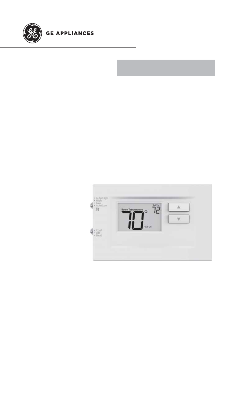
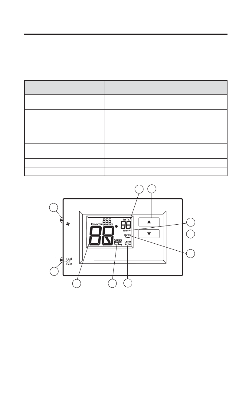
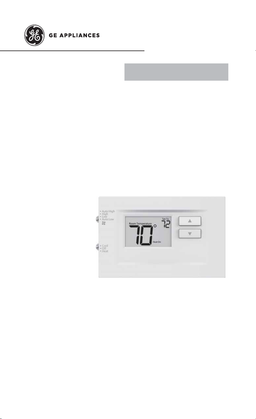
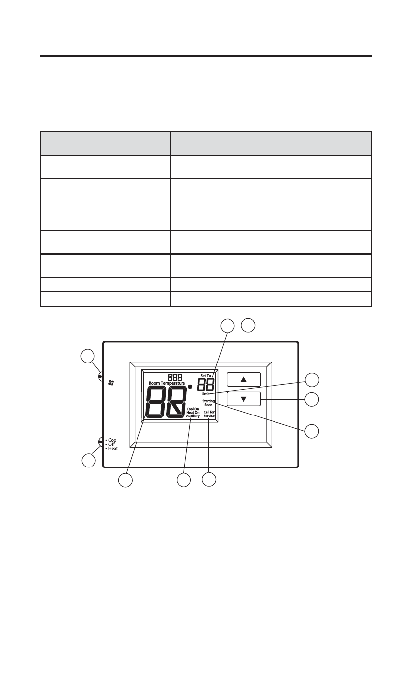
THERMOSTAT OVERVIEW
Before you begin using your thermostat, you should be familiar with its
features, display and the location/operation of the thermostat buttons and
switches.
THERMOSTAT BUTTONS AND
SWITCHES
THE DISPLAY
1.) Fan Switch 5.) Thermostat is protecting the equipment from short
cycling (5-minute delay)
2.) System Switch 6.) Indicates that the system is running in cool, heat
or auxiliary mode (The auxiliary will run in Heat
mode when the heat pump cannot maintain the set
temperature.)
3.) Raises Temperature Setting 7.) Temperature setpoint
4.) Lowers Temperature Setting 8.) Displays when the thermostat setpoint has reached
the maximum or minimum setting.
9.) Room Temperature
10.) SEE TROUBLESHOOTING
• Auto High
• High
• Low
• Auto Low
1
3
4
2
8
9
5
6
10
7
8 49-5000769 Rev. 1
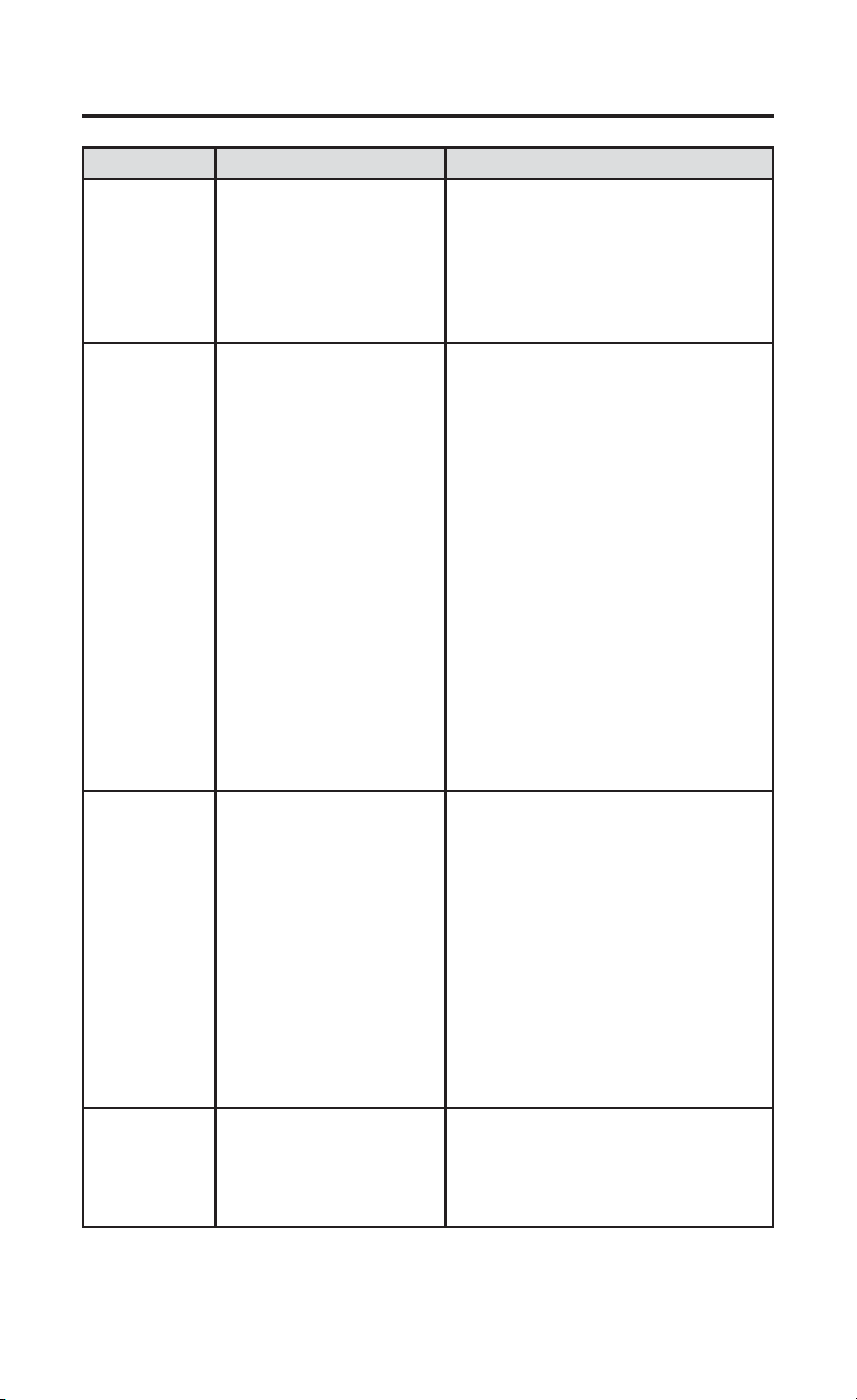
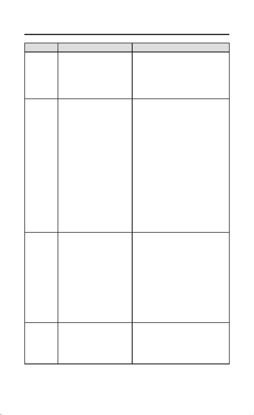
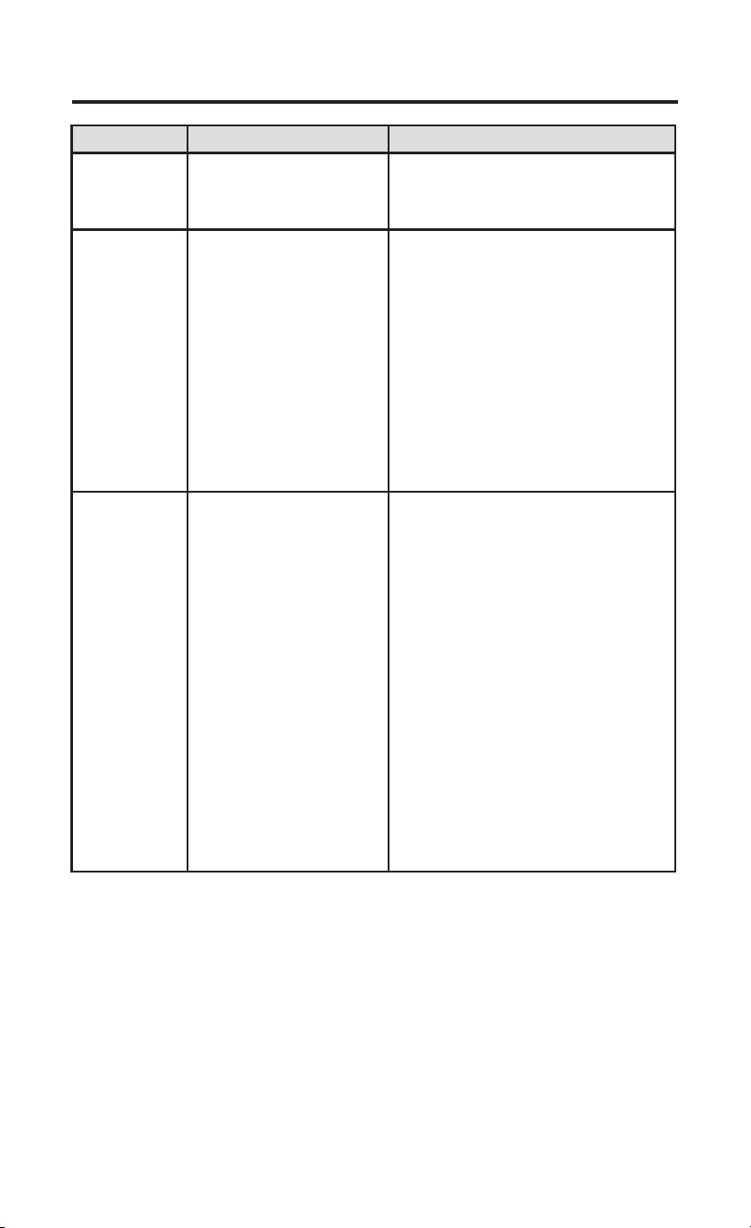
TROUBLESHOOTING
Symptom Possible Cause Corrective Action
No Heat/
No Cool/
No Fan
(common
problem)
1.) Blown fuse or tripped
circuit breaker
2.) HVAC unit unpowered
3.) HVAC unit not set for
remote thermostat control
4.) Loose connection to
thermostat or system
1.) Replace fuse or reset breaker
2.) Restore power to HVAC unit
3.) Enable wall thermostat control on
HVAC unit
4.) Tighten Connections
No Heat/
No First
Stage Heat
1.) System Switch not set
to Heat
2.) Loose connection to
thermostat or system
3.) Heating System
requires service or
thermostat requires
replacement
4.) Misconfiguration
between menu item 20
and jumper wire.
Verify thermostat and system wires
are securely attached.
Diagnostic: Set System Switch to
Heat and raise the setpoint above
room temperature. Within five
minutes the thermostat should make
a soft click sound and “Heat On”
should appear on display. This sound
indicates the thermostat is operating
properly. If the thermostat does not
click, try the reset operation listed
below. If the thermostat does not click
after being reset, contact your heating
and cooling service person or place
of purchase for a replacement. If the
thermostat clicks, contact the furnace
manufacturer or a service person to
verify the heating system is operating
correctly. Make sure that menu item
20 and the jumper wire match.
No Cool 1.) System Switch not set
to Cool
2.) Loose connection to
thermostat or system
3.) Cooling System
requires service or
thermostat requires
replacement
Verify thermostat and system wires
are securely attached.
Diagnostic: Set System Switch to
Cool and lower setpoint below room
temperature. Same procedures as
diagnostic for “No Heat” condition
except set the thermostat to Cool
and lower the setpoint below the
room temperature. There may be
up to a five minute delay before
the thermostat clicks in Cooling if
the compressor lock-out option is
selected in the installer menu. (see
INSTALLER MENU, item 50)
Heat, Cool
or Fan Runs
Constantly
Possible short in wiring,
thermostat, heat, cool or
fan system
Check each wire connection to verify
they are not shorted or touching other
wires. Try resetting the thermostat.
If the condition persists contact your
HVAC service person.
49-5000769 Rev. 1 9
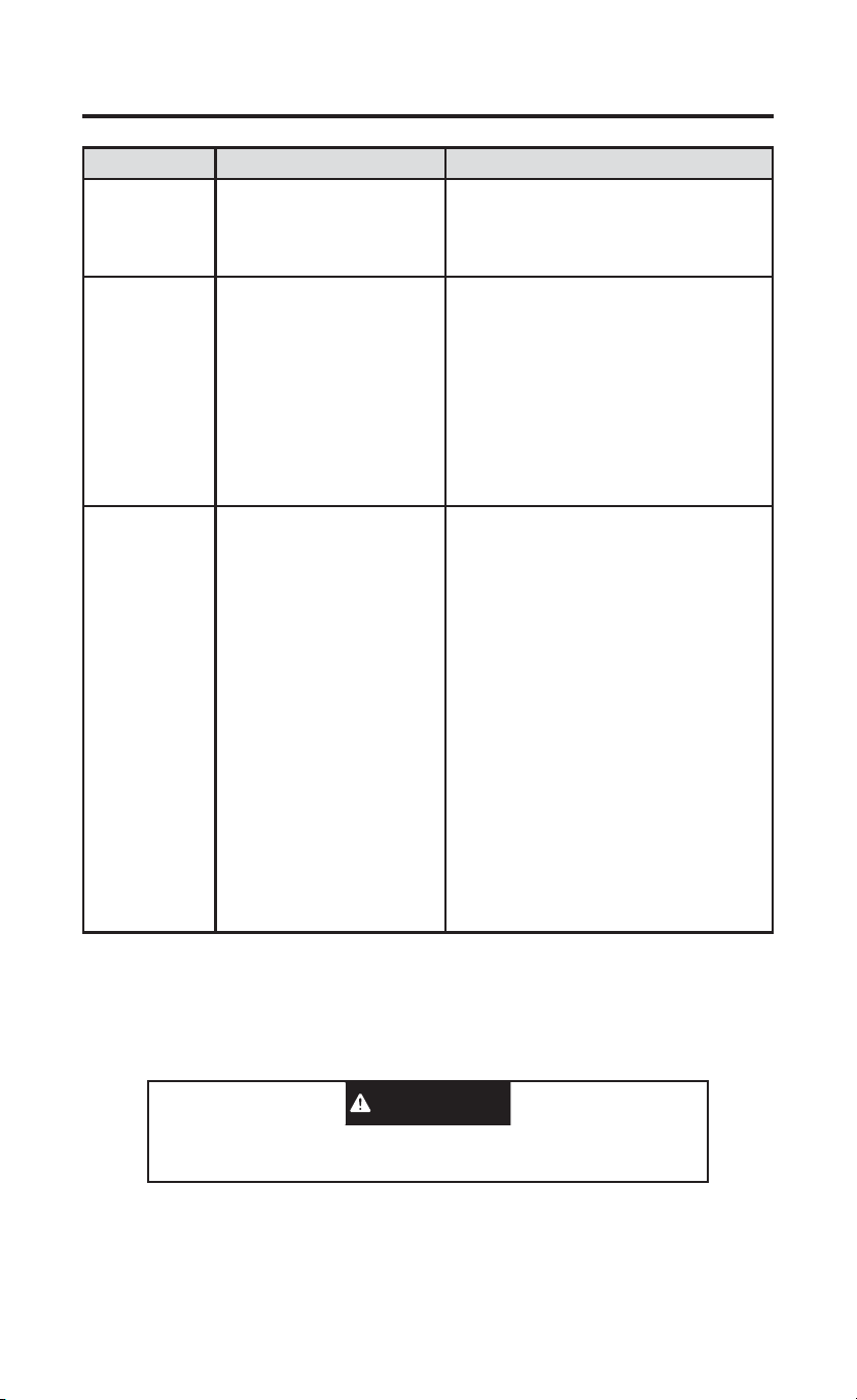
TROUBLESHOOTING
Symptom Possible Cause Corrective Action
Thermostat
Display &
Thermometer
Disagree
Thermostat display
requires adjustment
Display can be adjusted +/-5°. See
User Menu item 04
Furnace (Air
Conditioner)
Cycles Too
Fast or Slow
(narrow
or wide
temperature
swing) / No
First Stage
Heat
1.) The location of
the thermostat and/
or the size of the
Heating System may be
influencing the cycle rate
2.) Misconfiguration
between menu item 20
and jumper wire.
Digital thermostats provide precise
control and cycle faster than older
mechanical models. The system turns
on and off more frequently, but runs
for a shorter time. If you would like
to increase cycle time, choose SLO
for slow cycle in the Installer menu.
(Reference menu items 30 & 35) If an
acceptable cycle rate is not achieved,
contact your HVAC service person.
“Call for
Service” icon
appears on
displayed
1.) Heating system is not
able to heat the space to
within 10 degrees of the
setpoint within 2 hours
2.) Cooling system is not
able to cool the space to
within 10 degrees of the
setpoint within 2 hours
3.) If “--” is displayed for
the Room Temperature,
a replacement thermostat
is needed
4.) None of the buttons
operate on the thermostat
5.) If “Call for Service” is
flashing, compressor self
diagnostic is detecting
an issue with the outdoor
unit
1.) See corrective action for “No
Heat”
2.) See corrective action for “No
Cool”
3.) Replace thermostat
4.) Check for stuck buttons
5.) Contact a service person to verify
the equipment is operating correctly
Resetting the Thermostat or Thermostat Settings
To conveniently reset only the user settings back to factory defaults, press
ŸDQGźEXWWRQVZKLOHPRYLQJWKHV\VWHPVZLWFKIURPOFF to HEAT at
the same time and hold until the display goes blank and resets.
This product contains a chemical known to the state of California to cause
cancer and birth defects and other reproductive harm.
WARNING
10 49-5000769 Rev. 1
FCC STATEMENT
NOTE: This equipment has been tested and found to comply with
the limits for a Class B digital device, pursuant to part 15 of the FCC
Rules. These limits are designed to provide reasonable protection
against harmful interference in a residential installation. This equipment
generates, uses and can radiate radio frequency energy and, if not
installed and used in accordance with the instructions, may cause
harmful interference to radio communications. However, there is no
guarantee that interference will not occur in a particular installation. If
this equipment does cause harmful interference to radio or television
reception, which can be determined by turning the equipment off and
on, the user is encouraged to try to correct the interference by one or
more of the following measures:
• Reorient or relocate the receiving antenna
• Increase the separation between the equipment and receiver
• Connect the equipment into an outlet on a circuit different from that to
which the receiver is connected
• Consult the dealer or an experienced radio/TV technician for help
CAN ICES-003 (B) / NMB-003 (B)
TECHNICAL SUPPORT: 1-844-434-7822 Option 1
SPÉCIFICATIONS ..............................2
INSTALLATION DU THERMOSTAT
CÂBLAGE .......................................3
MENU DE L’INSTALLATEUR ........4
MISE À L’ESSAI DE
L’ÉQUIPEMENT ............................. 6
UTILISATION DU THERMOSTAT
APERÇU DU THERMOSTAT ...........7
DÉPANNAGE .....................................8
RÉINITIALISATION ........................ 9
DÉCLARATION DE LA FCC : ...........10
THERMOSTAT
Câblé, 2 vitesses de ventilateur
MANUEL D’UTILISATION ET
INSTRUCTIONS D’INSTALLATION
RAK149F2A
49-5000769 Rev. 1 11-23
2 49-5000769 Rev. 1
SPÉCIFICATIONS
AVIS RELATIF AU MERCURE : Ce produit ne contient pas de mercure. Il
peut toutefois remplacer un produit qui en contient. Le mercure et les produits
contenant du mercure ne doivent pas être jetés dans les ordures ménagères.
Consultez le site thermostat-recycle.org pour connaître les endroits où vous
pouvez envoyer le produit contenant du mercure.
Paramètres électriques :
Câblé 20 à 30 V c.a., NEC classe II, 50/60 Hz
Charge à la borne 1,5 A par borne, 2,5 A maximum pour toutes
les bornes combinées
Plage de réglage 60°F à 85°F (16°C à 29°C)
Différentiels nominaux (@ 6 °F/h) Rapide Moyen Lent
Thermopompe (chauffage) 0,9ºF 1,2ºF 1,7ºF
Thermopompe (climatisation) 0,9ºF 1,2ºF 1,7ºF
Chauffage auxiliaire 0,5ºF 0,75ºF 1,9ºF
Température ambiante de
fonctionnement
32 °F à +105 °F (0 à +41 °C)
Plage de températures affichées 32 °F à +99 °F (0 à 37 °C)
Humidité de fonctionnement 90 % max. sans condensation
Plage de températures
d’expédition
-20 °F à + 150 °F (-29 à +65 °C)
Dimensions du thermostat 3-3/4 po H x 6 po L x 1-1/8 po P
Applications du thermostat
Nombre maximum d’étages chauffage/
climatisation
Refroidissement à une étape, chauffage
à une ou deux étapes – REMARQUE :
Chauffage à deux étages = 1er étage
par thermopompe et 2e étage par
résistance.
2/1
49-5000769 Rev. 1 3
INSTALLATION DU THERMOSTAT
CÂBLAGE
Consultez le mode d’emploi du fabricant de l’appareil pour les informations
spécifiques au câblage du système. Après le câblage, consultez la section
MENU DE L’INSTALLATEUR pour configurer correctement le thermostat.
Les schémas de câblage illustrés correspondent aux systèmes typiques, et
ils décrivent les fonctions des bornes du thermostat.
Désignation de la borne Fonction de la borne
GL Relais de ventilateur basse vitesse
R Alimentation (24 V)
O/B Borne de permutation; énergisée en mode climatisation (O)
ou chauffage (B) pour la thermopompe Remarque: Toutes les
applications Zoneline/Hotpoint sont des thermopompes de type B.
Y Compresseur 1er étage, mode chauffage et climatisation
GH Relais de ventilateur à grande vitesse
W Mode chauffage – chauffage 2e étage (électrique)
C Fil commun pour 24 V
Précautions
• Ne dépassez pas les spécifications nominales.
• Tout le câblage doit respecter les codes et ordonnances locaux et
nationaux de l’électricité.
• Ce contrôleur est un instrument de précision et il doit être manipulé
soigneusement. Une manipulation brusque ou la déformation des
composantes peut causer la défaillance du contrôleur.
Mise de niveau du thermostat
La mise de niveau du thermostat n’est
qu’à des fins esthétiques et n’affectera
pas son fonctionnement.
Pour prévenir les chocs électriques et
les dommages à l’équipement, coupez
l’alimentation électrique du système dans
la boîte principale de disjoncteurs jusqu’à
ce que l’installation soit terminée.
ATTENTION
N’utilisez pas cet appareil sur des circuits dont
la tension est supérieure à celle indiquée. Une
tension plus élevée endommagera la commande
et pourrait présenter un risque de choc électrique
ou d’incendie. Ne court-circuitez pas les bornes
sur la vanne à gaz ou la commande principale.
Un câblage court-circuité ou incorrect grillera le
thermostat et pourrait causer des blessures ou
des dommages à la propriété.
AVERTISSEMENT
4 49-5000769 Rev. 1
CÂBLAGE (cont)
Instructions: Pour convertir le système de PTHP à PTAC, modifiez
l’élément de menu no 20 de HP (défaut) à AC. De plus, si vous utilisez ce
thermostat sur un climatiseur terminal monobloc (PTAC) Hotpoint, vous
devrez couper le fil de cavalier situé à l’arrière du thermostat.
REMARQUE : L’élément de menu #32 ne s’affichera pas en mode AC.
1.) Sélecteur de borne O/B
Le sélecteur O/B sur ce thermostat est réglé en usine à la position B. Cela
conviendra des applications de thermopompe, qui exigent que le relais de
permutation soit énergisé en mode Heat (chauffage). Si la thermopompe
installée exige qu’une borne O énergise le relais de permutation en mode
Cool (climatisation), le sélecteur O/B doit être réglé à la position O.
MENU DE L’INSTALLATEUR
Pour accéder au MENU DE L’INSTALLATEUR, placez le sélecteur
du système à la position OFF, puis enfoncez et tenez les boutons
ŸHWźSHQGDQWVHFRQGHV/¶DIILFKHXULQGLTXHO¶DUWLFOHGDQVOH
WDEOHDXFLGHVVRXV(QIRQFH]VLPXOWDQpPHQWOHVERXWRQVŸHWźGHOD
WHPSpUDWXUHSRXUQDYLJXHUHQWUHOHVDUWLFOHVDXPHQX(QIRQFH]ŸRXź
pour changer un réglage au menu. Pour quitter le menu de l’installateur à
tout moment, placez le commutateur du système sur Heat ou Cool.
INSTALLATION DU THERMOSTAT
1
Fil de
cavalier
49-5000769 Rev. 1 5
MENU DE L’INSTALLATEUR (cont)
INSTALLATION DU THERMOSTAT
Num. de
menu
d’installateur
(enfoncez
Menu 3
secondes)
Description Réglage par
défaut
(icônes
clignotantes)
Réglages
DSSX\H]VXUŸRXź
20
Algorithme - AC ou HP (Si HP est
sélectionné, l’élément #32 sera
affiché)
HP HP – Pompe à chaleur
ou
AC – Climatiseur
30 CR
Vitesse du cycle de chauffage
(à quelle fréquence le chauffage
s’activera)
SLO SLO – lent
MEd – moyen
FAS – rapide
32 CR
Vitesse du chauffage auxiliaire
(à quelle fréquence le chauffage
auxiliaire s’activera) Remarque:
Disponible si HP est sélectionné
sur l’article #20
SLO SLO – lent
MEd – moyen
FAS – rapide
35 CR
Vitesse du cycle de climatisation
(à quelle fréquence la
climatisation s’activera)
SLO SLO – lent
MEd – moyen
FAS – rapide
50 CL
Verrouillage du compresseur
(protège le compresseur contre
les cycles trop courts)
OFF On – délai de 5 minutes
OFF – aucun délai
65
Temp. de chauffage maximale
(point de consigne maximal pour
le chauffage)
85°F 45°F à 99°F
66
Temp. de climatisation minimale
(point de consigne minimal pour
la climatisation)
60°F 45°F à 99°F
79 Fahrenheit ou Celsius °F °F – Fahrenheit
°C – Celsius
81
Réglage de la température
affichée (règle la « température
ambiante » affichée)
0 -5 à +5
83 dL
Éclairage continu de l’affichage
(garde le rétroéclairage toujours
activé – fil commun requis)
OFF On – toujours allumé
OFF – momentanément
allumé pendant 8
secondes

6 49-5000769 Rev. 1
INSTALLATION DU THERMOSTAT
MISE À L’ESSAI DE L’ÉQUIPEMENT
Ouvrez l’alimentation électrique du système.
Fonctionnement du ventilateur
1.) Placez le sélecteur du ventilateur à la position basse. Le ventilateur
devrait commencer à fonctionner à basse vitesse.
2.) Placez le sélecteur du ventilateur à la position basse automatique. La
ventilation devrait s’arrêter immédiatement.
3.) Placez le sélecteur du ventilateur à la position haute. Le ventilateur
devrait commencer à fonctionner à grande vitesse.
4.) Placez le sélecteur du ventilateur à la position haute automatique. La
ventilation devrait s’arrêter immédiatement.
Système de chauffage
1.) Placez le sélecteur du ventilateur à la position Heat (chauffage).
2.) Enfoncez
Ÿ pour régler le thermostat à 1° au-dessus de la
température ambiante. Le chauffage de 1er étage devrait commencer à
fonctionner.
6LOHFKDXIIDJHSDUUpVLVWDQFHGHHpWDJHHVWXWLOLVpDSSX\H]VXUŸ
pour régler le thermostat à 3° au-dessus de la température ambiante.
Le chauffage par résistance devrait commencer à fonctionner.
$SSX\H]VXUźSRXUUpJOHUOHWKHUPRVWDWjHQGHVVRXVGHOD
température ambiante. Le système de chauffage devrait cesser de
fonctionner.
Système de climatisation
1.) Placez le sélecteur du système à la position Cool (climatisation).
2.) Enfoncez
ź pour régler le thermostat à 1° sous la température
ambiante. Le ventilateur devrait se mettre en marche immédiatement,
puis l’air froid devrait se mettre à circuler. Le thermostat indiquera Cool
On (climatisation en marche). Il peut y avoir un délai allant jusqu’à 5
minutes. (Voir MENU DE L’INSTALLATEUR, article 50.)
3.) Enfoncez
Ÿ pour régler le thermostat à 1° au-dessus de la
température ambiante. Le système de refroidissement devrait cesser de
fonctionner.
REMARQUE : La position par défaut du verrouillage du compresseur est
OFF (éteint) dans le menu INSTALLER (INSTALLATEUR), élément 50.
Lorsque le verrouillage du compresseur est activé (ON), l’écran affiche
Starting Soon (Démarrage bientôt) Si Starting Soon (Démarrage bientôt)
s’affiche, la fonction de verrouillage du compresseur est activée. Il y aura
un délai allant jusqu’à 5 minutes avant la mise en marche du compresseur.
49-5000769 Rev. 1 7
UTILISATION DU THERMOSTAT
APERÇU DU THERMOSTAT
Avant d’utiliser le thermostat, vous devriez être familier avec ses fonctions,
son affichage et l’emplacement/le fonctionnement des boutons et
sélecteurs du thermostat.
BOUTONS ET SÉLECTEURS
DU THERMOSTAT
AFFICHAGE
1.) Sélecteur du ventilateur 5.) Le thermostat protège l’équipement contre les cycles
trop courts (délai de 5 minutes)
2.) Sélecteur du système 6.) Indique que le système fonctionne en mode
climatisation, chauffage ou auxiliaire (le mode
auxiliaire fonctionnera en mode chauffage si la
thermopompe ne peut pas maintenir la température
programmée).
3.) Élève le réglage de la
température
7.) Point de consigne de température
4.) Diminue le réglage de la
température
8.) S’affiche lorsque le point de consigne du thermostat
a atteint le réglage maximum ou minimum.
9.) Température ambiante
10.) VOIR LE GUIDE DE DÉPANNAGE
• Auto High
• High
• Low
• Auto Low
1
3
4
2
8
9
5
6
10
7
8 49-5000769 Rev. 1
DÉPANNAGE
Problème Cause possible Mesure corrective
Chauffage,
climatisation
ou
ventilateur
non
fonctionnels
(problème
courant)
1.) Fusible grillé ou disjoncteur
déclenché.
2.) Appareil non alimenté.
3.) Appareil non réglé pour
commande de thermostat à
distance
4.) Branchement desserré sur le
thermostat ou le système.
1.) Remplacez le fusible ou réenclenchez
le disjoncteur.
2.) Rétablissez l’alimentation à l’appareil.
3.) Activez la commande du thermostat
mural sur l’appareil.
4.) Serrez les connexions.
Chauffage
non / Pas
de chaleur
de première
étape
1.) Sélecteur du système non
réglé sur le chauffage
2.) Branchement desserré sur le
thermostat ou le système.
3.) Entretien de l’appareil de
chauffage ou remplacement du
thermostat requis.
4.) Mauvaise configuration entre
l’élément de menu 20 et le
cavalier.
Vérifiez que le thermostat et les fils du
système sont bien serrés en place.
Diagnostic : Réglez le sélecteur système
à Heat (chauffage) et haussez le point de
consigne au-dessus de la température
ambiante. Le thermostat devrait émettre
un léger déclic dans les cinq minutes
et « Heat On » devrait apparaître à
l’affichage. Ce bruit indique que le
thermostat fonctionne correctement. Si
le thermostat n’émet pas de déclic,
effectuez l’opération de réinitialisation
décrite après ce tableau. Si le thermostat
n’émet toujours pas de déclic après
la réinitialisation, communiquez avec
un spécialiste du chauffage ou de la
climatisation ou le magasin où vous avez
acheté le thermostat pour demander un
remplacement. Si le thermostat émet un
déclic, communiquez avec le fabricant de
la fournaise ou un technicien pour vérifier
si le chauffage fonctionne correctement.
Assurez-vous que l’élément de menu 20 et
le fil du cavalier correspondent.
Pas de
climatisation
1.) Commutateur système pas
réglé à Cool.
2.) Branchement desserré sur le
thermostat ou le système.
3.) Entretien de l’appareil de
climatisation ou remplacement
du thermostat requis.
Vérifier que le thermostat et les fils du
système sont bien serrés en place.
Diagnostic : Réglez le commutateur
système à Cool et baissez le point de
consigne en deçà de la température
ambiante. Identique au diagnostic en
cas d’absence de chauffage, sauf que
le thermostat doit être réglé sur Cool
(climatisation) et le point de réglage doit
être inférieur à la température ambiante. Il
peut se produire un délai de cinq minutes
avant que le thermostat émette un déclic
en mode climatisation si l’option de
verrouillage du compresseur est choisie
dans le menu de l’installateur. (Voir MENU
DE L’INSTALLATEUR, article 50.)
Le
chauffage, la
climatisation
ou le
ventilateur
n’arrête
jamais
Court-circuit possible dans
le câblage, le thermostat ou
le système de chauffage/
climatisation/ventilation
Vérifiez tous les branchements du câblage
pour vous assurer qu’ils ne sont pas court-
circuités ni en contact avec d’autres fils.
Réinitialisez le thermostat. Si le problème
persiste, communiquez avec votre
technicien en CVC.
49-5000769 Rev. 1 9
DÉPANNAGE
Problème Cause possible Mesure corrective
Le point de
consigne et le
thermomètre ne
concordent pas
Le thermomètre du
thermostat doit être ajusté.
Le thermomètre peut être réglé de +/- 5°.
Voir le menu de l’utilisateur, article 04.
La cadence de
l’appareil de
chauffage (ou
du climatiseur)
est trop rapide
ou trop lente
(variation de
température
trop grande ou
trop restreinte) /
Pas de chaleur
de première
étape
1.) L’emplacement du
thermostat et la taille du
système de chauffage
peuvent affecter la durée du
cycle.
2.) Mauvaise configuration
entre l’élément de menu 20
et le cavalier.
Les thermostats numériques offrent un
contrôle précis et un cycle plus rapide
que les anciens modèles mécaniques.
Le système se met en marche et à l’arrêt
plus fréquemment, mais il fonctionne
moins longtemps. Pour accroître la durée
des cycles, sélectionnez SLO, pour cycle
lent, dans le menu de l’installateur. (Voir
les articles du menu 30 et 35.) Si une
durée de cycle acceptable ne peut pas
être atteinte, contactez un technicien
en CVC local pour des suggestions
supplémentaires. Assurez-vous que
l’élément de menu 20 et le fil du cavalier
correspondent.
L’icône « Call
for Service »
(Appeler le
technicien)
apparaît
1.) Le système de chauffage
n’est pas en mesure de
chauffer l’espace à 10 degrés
près du point de consigne
dans les 2 heures.
2.) Le système de
climatisation n’est pas en
mesure de refroidir l’espace
à 10 degrés près du point de
consigne dans les 2 heures.
3.) Si « -- » est affiché au
lieu de la température de la
pièce, il faut remplacer le
thermostat.
4.) Aucun des boutons ne
fonctionne sur le thermostat.
5.) Si « Call for Service
» (Appeler le technicien)
clignote, l’auto-diagnostic
du compresseur a détecté
un problème avec l’appareil
extérieur.
1.) Voir la mesure corrective pour « Pas de
chauffage ».
2.) Voir la mesure corrective pour « Pas de
climatisation ».
3.) Remplacez le thermostat.
4.) Vérifiez si des boutons sont bloqués.
5.) Communiquez avec un technicien pour
vérifier que l’équipement fonctionne bien.
Réinitialisation du thermostat ou de ses réglages
Pour rétablir les paramètres d’usine par défaut uniquement, appuyez sur
OHVERXWRQVŸHWźWRXWHQGpSODoDQWOHFRPPXWDWHXUGXV\VWqPHGH
OFF à HEAT et maintenez-le enfoncé jusqu’à ce que l’écran s’efface et se
réinitialise.

10 49-5000769 Rev. 1
CAN ICES-003 (B) / NMB-003 (B)
DÉCLARATION DE LA FCC
REMARQUE : Cet équipement a été testé et déclaré conforme aux
limites d’un dispositif numérique de Classe B, conformément à la partie
15 des règles de la FCC. Ces limites sont définies afin d’assurer une
protection raisonnable contre le brouillage nuisible dans une installation
résidentielle. Cet équipement génère, utilise et émet des fréquences
radio qui, en cas d’une installation erronée ou d’une utilisation non-
conforme aux instructions de ce manuel d’utilisation peuvent causer
un brouillage nuisible aux communications radio. Cependant, il n’y a
aucune garantie qu’un brouillage nuisible ne se produira pas dans une
installation particulière. Si cet équipement cause un brouillage nuisible
sur votre poste radio ou de télévision, ce que vous pouvez déterminer
en éteignant et en rallumant votre équipement, il est conseillé à
l’utilisateur d’essayer de pallier ce brouillage nuisible en prenant l’une
ou l’autre des mesures suivantes :
• Réorienter ou déplacer l’antenne de réception.
• Augmenter la distance entre l’équipement et le récepteur.
• Brancher l’équipement dans une prise d’un circuit qui diffère de celui
auquel le récepteur est branché.
• Consulter le revendeur ou un technicien en radio-télévision pour
obtenir de l’aide.
SOUTIEN TECHNIQUE : 1-844-434-7822 option 1
