Loading ...
Loading ...
Loading ...
28 29
STEP 4. Anchor the side angles (Item 6) by engaging the tabs of the
lower sill plate (see Figure 57, Detail B-2) with the loops of the
side angle. Engage the tabs of the top angle (Item 5) with the top
loops of the side angle (see Figure 57, Detail B-1). Install two (2)
screws (Item 7) to secure the top angle tabs and the side angle
to cabinet (see Figure 57, Detail B-1).
RETAINER SCREWS
AND WASHERS
FAR RIGHT
SCREW
ENTRYGARD
RETAINER
WIRE
Figure 55
FRR012
Figure 54
FRR011
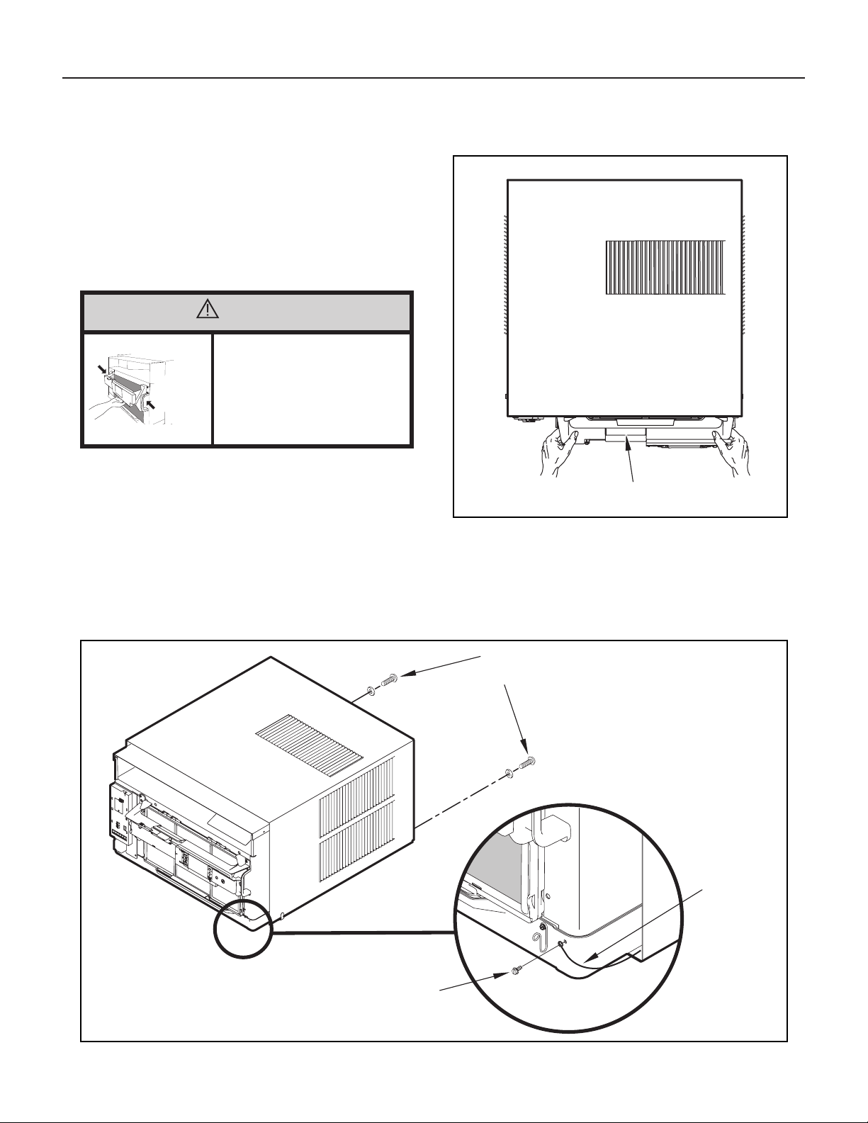
CONTROL UNIT
SUPPORT BRACKET
CAUTION
Handle Use
Use handle on both sides to
pull unit from sleeve.
Do not push, pull, or lift from
center of support.
Use Handle
Locations
(both sides)
Standard Window Installation
STEP 2. Hold the cabinet stationary. Then, use the hand grips on both
ends of the control unit support bracket to pull the chassis out of
the cabinet (see Figure 55).
STEP 3. Remove the large white foam blocks used to restrain the
compressor during shipment (see Figure 56). Inspect base pan
for dislodged white foam blocks and remove. Do not remove
any other foam parts.
NOTE: Hardware and accessories used during installation are shown
on Page 28. Each part will be referred as “Item No.”
STEP 1. Remove the chassis EntryGard
™
retainer by removing the far
right screw (see Figure 54). Save this screw to reattach the
chassis retainer after installation (Step 12). Also, remove and
discard the two retainer screws and washer located at the rear
of the unit (see Figure 54).
Loading ...
Loading ...
Loading ...