Loading ...
Loading ...
Loading ...
7
GAS REQUIREMENTS
NOTE: DO NOT use any tape, pipe dope or
threading compound on any flare fiing. This
will cause a clog in the regulator and prevent
your grill from functioning properly.
LIQUID PROPANE TANK REQUIREMENTS
NATURAL GAS REQUIREMENTS
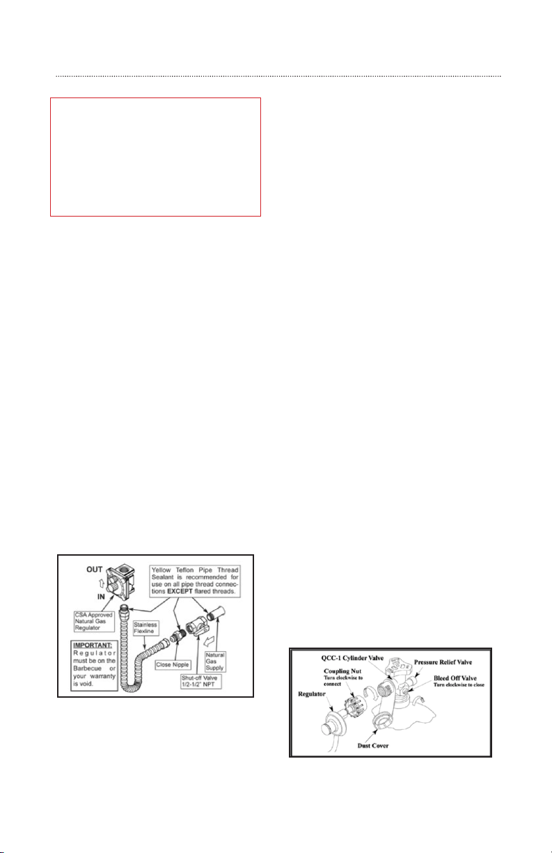
CONNECTING TO THE NG REGULATOR
Turn off the gas at the supply when grill is not
in use.
Please ensure:
• Summerset Professional Grills
recommends that only qualified
professionals perform the required
plumbing on this product.
• Check the Rating Plate to make sure the
gas supply you are hooking up to is the
gas type the grill is manufactured for.
• To ensure satisfactory performance,
the gas supply line must be sized
to accommodate the total BTU
requirements of all the gas-fired
equipment that will be connected to
that line.
• In no case should pipe less than 1/2”
inside diameter or 1” outside diameter
ever be used to connect this product.
• The LP gas tank has a shutoff valve,
terminating in an LP gas supply tank
valve outlet that is compatible with a
Type 1 tank connection device. The LP
gas tank must also have a safety relief
device that has a direct communication
with the vapor space of the tank.
• The tank supply system must be
arranged for vapor withdrawal.
• The LP gas tank used must have a collar
to protect the tank valve.
CONNECTING TO THE LP TANK
Never connect an unregulated LP gas tank
to your gas grill. The gas regulator assembly
supplied with your gas grill is adjusted to have
an outlet pressure of an estimated 11” water
column (W.C.) for connection to an LP gas tank.
The hose and regulator are connected in the
following manner:
• Use a standard 20 lbs. LP tank with QCC
– 1 fiing
• Grills set up for LP gas come equipped
with an LP hose regulator assembly
for connection to a standard 20 lbs. LP
cylinder (Type 1)
• Insert the regulator inlet into the
cylinder valve and turn the black
coupling nut clockwise until the
coupling nut is hand tight. DO NOT
over-tighten this connection.
• To disconnect the coupling nut, first
make sure the main cylinder valve is
turned off. Grasp the coupling nut and
turn counter clockwise. The inlet will
then disengage.
IMPORTANT:
All installation and all installation parts
must conform to local codes with the
National Electrical Code, ANSI Z223.1/
NFPA 70 latest edition and the National
Fuel Gas Code ANSI Z223.1/NFPA 54 in
the U.S. and CGA-B149.1/.2 in Canada
Loading ...
Loading ...
Loading ...