
Scan for easy install video
http://san.us/401
We’ll Make It Stress-Free
If you have any questions along the way, just give us a call.
1-800-359-5520. We’re ready to help!
VST4 INSTRUCTION MANUAL
2
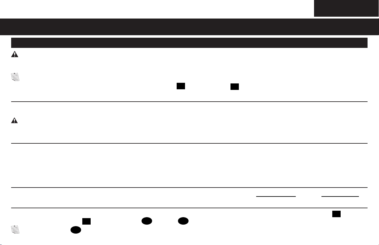
IMPORTANT SAFETY INSTRUCTIONS – SAVE THESE INSTRUCTIONS – PLEASE READ ENTIRE MANUAL PRIOR TO USE
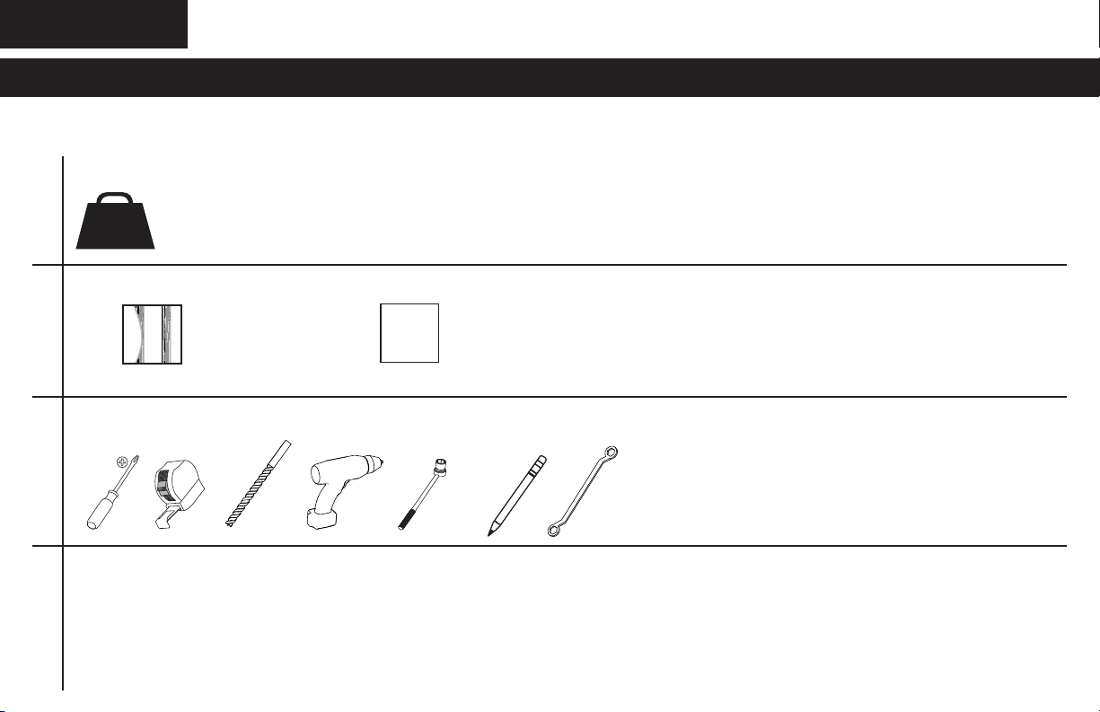
Before getting started, let’s make sure this mount is perfect for you!
2
What is your wall made of?
3
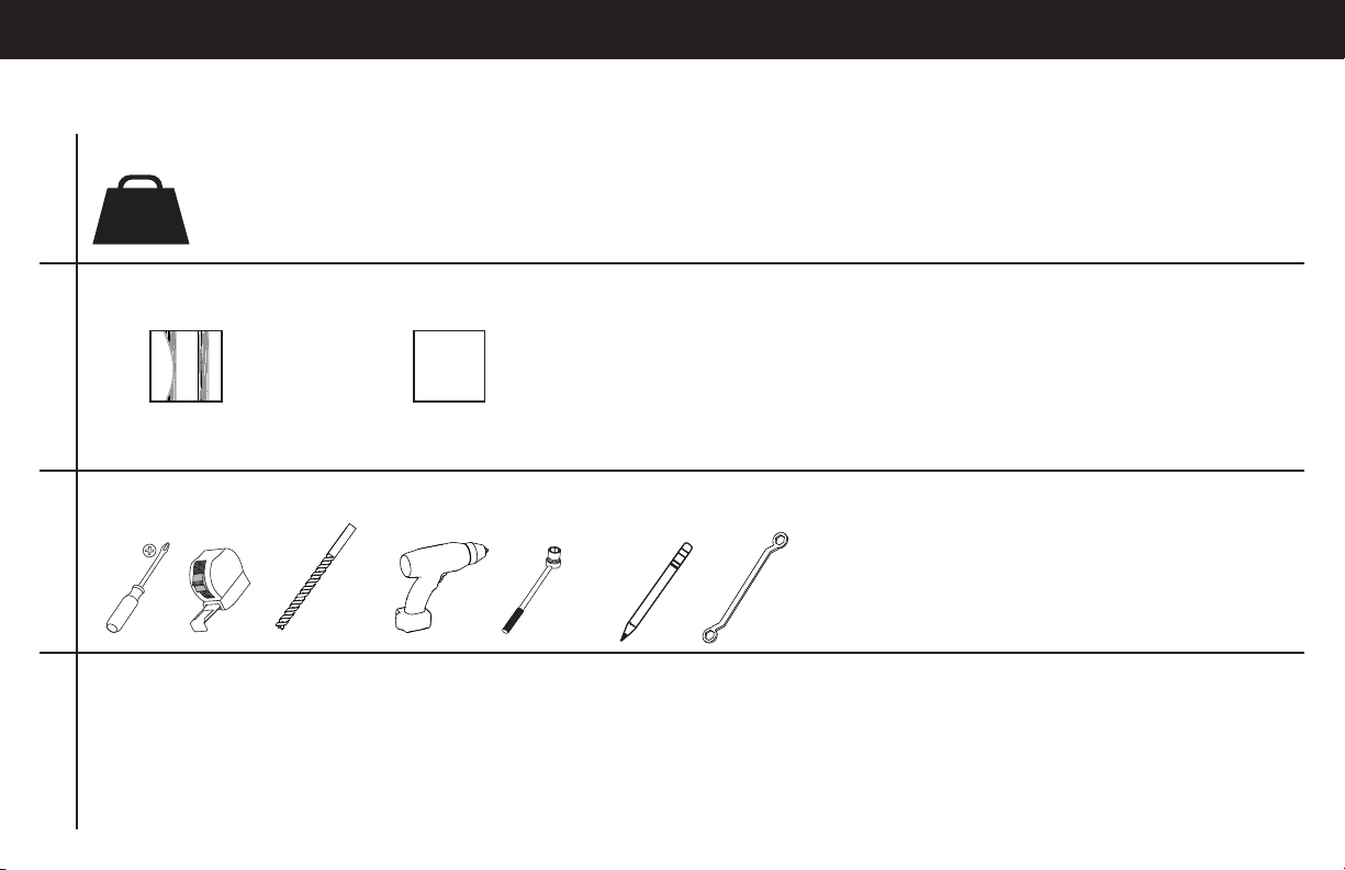
Do you have all of the tools needed?
4
Ready to begin?
Please read through these instructions completely to be sure you’re comfortable with this easy install process. Also check your TV
owner’s manual to see if there are any special requirements for mounting your TV.
If you do not understand these instructions or have doubts about the safety of the installation, assembly or use of this product, contact
Customer Service at 1-800-359-5520 (UK: 0800-056-2853).
1
Does your TV weigh more than 50 lb (22.7 kg) including accessories?
No — Perfect!
Yes — This mount is NOT compatible. Visit MountFinder.Sanus.com or call 1-800-359-5520 (UK: 0800-056-2853) to fi nd a compatible mount.
?
Drywall with
wood studs
Perfect!
Unsure?
Call 1-800-359-5520 (UK: 0800-056-2853)
50 lb
(22.7 kg)
12 mm
(7/16 in.)
3 mm
(1/8 in.)
Wood
10 mm
(3/8 in.)
3
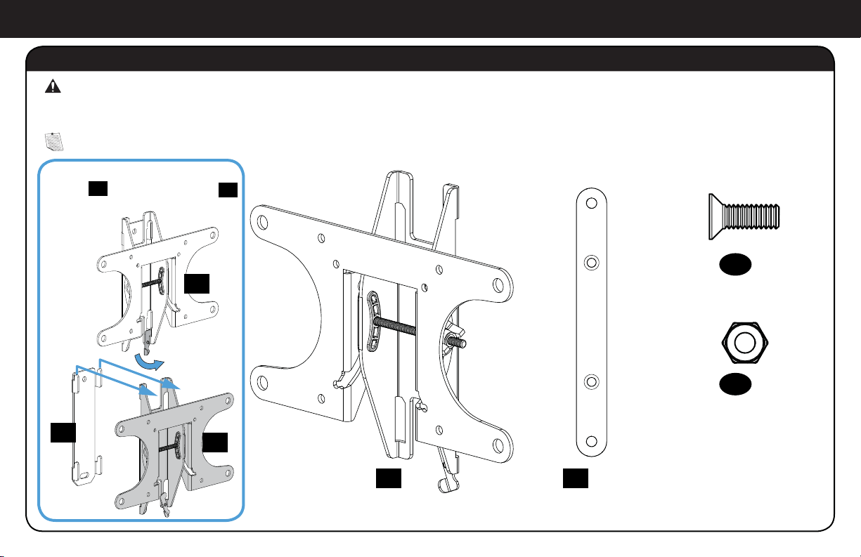
STEP 1 Attach Bracket to TV
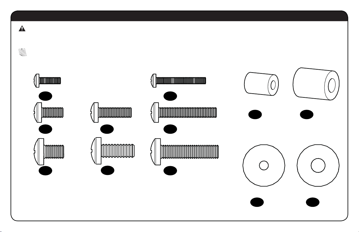
WARNING: This product contains small items that could be a choking hazard if swallowed.
Before starting assembly, verify all parts are included and undamaged. If any parts are missing or damaged, do not return the damaged
item to your dealer; contact Customer Service. Never use damaged parts!
Parts and Hardware for STEP 1
NOTE: Not all hardware included will be used.
*You may need to separate the TV
bracket
01
from the wall plate
18
before starting this step.
TV Bracket*
200 x 200 Extension
200 x 200 Extension Screw
200 x 200 Extension Nut
M6 x 12mm
02
x2
01
x1
03
x4
04
x4
01
01
18
4
WARNING: This product contains small items that could be a choking hazard if swallowed.
Before starting assembly, verify all parts are included and undamaged. If any parts are missing or damaged, do not return the damaged
item to your dealer; contact Customer Service. Never use damaged parts!
Parts and Hardware for STEP 1
NOTE: Not all hardware included will be used.
M4 M6/M8
M4 x 12mm
M6 x 12mm
M8 x 12mm
M4 x 30mm
M6 x 20mm M6 x 35mm
M8 x 35mm
M8 x 20mm
M4
M6/M8
05
x4
07
x4
10
x4
12
x4
11
x4
15
x8
16
x4
13
x4
14
x4
08
x4
09
x4
06
x4
TV Screws
TV Washers
TV Spacers
5
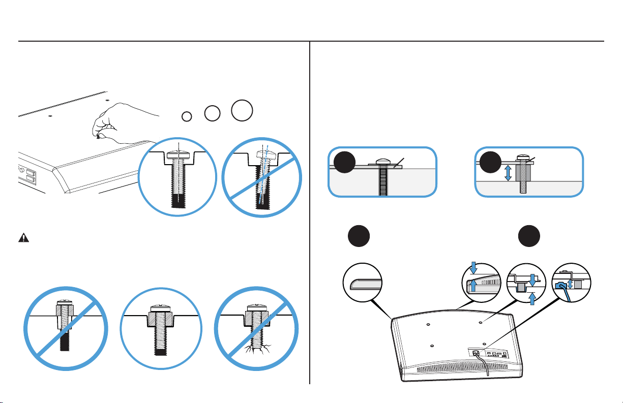
1-1 Select TV Screws
1-2 Spacers
Hand thread screws into the threaded inserts on the back of your TV
to determine which screw diameter (M4, M6, or M8) to use.
CAUTION: Verify adequate thread engagement of the screw/
spacer combination on your TV.
Too short will not hold the TV and too long will damage the TV.
M4
M6
M8
Too Short Correct Too Long
TV Bracket
TV Bracket
06
Round Back CablesInset HolesFlat Back
TV Bracket
A
A
B
B
Your TV type will help you determine which hardware
confi guration to use. Match your type of TV to the suggested
hardware confi guration on the next page.
A. Installation option without spacers (TVs with fl at backs).
B. Installation option using spacers (TVs with obstructed backs
or inset mounting holes).
6
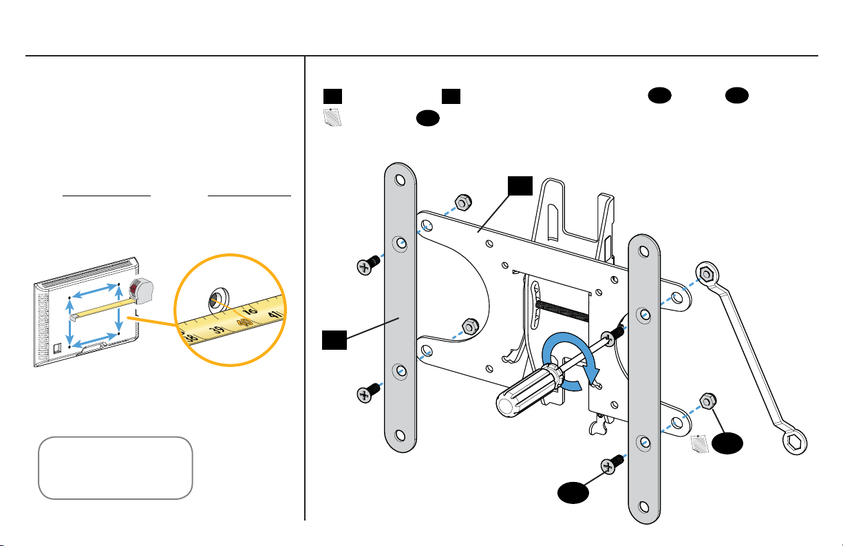
1-4 Attach Extensions (200 x 200 mm ONLY)1-3 Measure Your TV Hole Pattern
If mounting to a TV with a 200 x 200 mm (7 ⅞ x 7 ⅞ in.) hole pattern, add the extension plates
02
to the TV bracket
01
using the extension plate screws
03
and nuts
04
.
NOTE: Nuts
04
are poly-locks and will need to be forcibly tightened.
Measure the width and height of your
TV hole pattern in mm.
Record your measurements:
cm
inches
x Height
Width
mm mm
75 mm = 7.5 cm = 3 in.
100 mm = 10 cm = 4 in.
200 mm = 20 cm = 7 7/8 in.
inch dimensions approximate
02
01
04
03
7
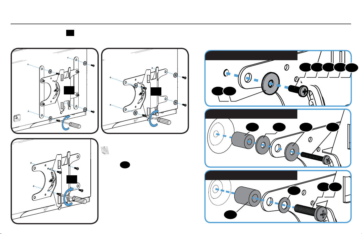
Position the TV bracket
01
over your TV hole pattern and install using the screw, washer, and spacer (if needed) combination you selected for
your TV.
M6/M8 spacer, screw, and washer
15 16
0615
16
14
13 15
M4/M6/M8 screw and washer
M4 spacer, screw, and washers
1-5 Attach TV Bracket
NOTE: If the hole pattern
on your TV is 75 x 75 mm the
washer
15
will not be used.
05 07 08 10
11
09 12
01
200 x 200 mm 200 x 100 mm
100 x 100 mm
75 x 75 mm
01
01
01
8
STEP 2 Attach Wall Plate to Wall
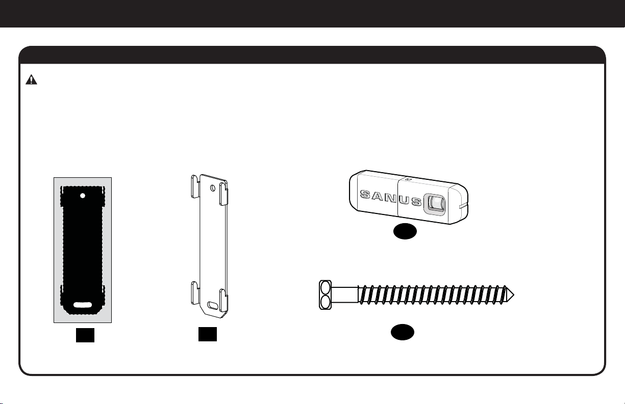
Parts and Hardware for STEP 2
WARNING: This product contains small items that could be a choking hazard if swallowed.
Before starting assembly, verify all parts are included and undamaged. If any parts are missing or damaged, do not return the damaged
item to your dealer; contact Customer Service. Never use damaged parts!
17
x1
18
x1
Wall Plate
Wall Plate
Template
1/4 x 2.5 in.
¼ x 2½ in.
20
x2
Sanus Magnetic Stud Finder
19
x1
Lag Bolts
9
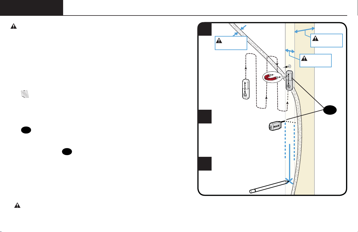
STEP 2
Wood Stud ONLY!
1
2
3
CAUTION: Avoid potential personal injuries and property damage!
● Drywall covering the wall must not exceed
16 mm (5/8 in.)
● Minimum wood stud size: common 51 x 102 mm (2 x 4 in.) nominal 38 x
89 mm (1½ x 3½ in.)
● Stud center must be verified
NOTE: See Introducing Sanus Magnetic Stud Finder* located in
your Welcome folder for more detailed operation of stud fi nder.
1. Locate a nail/screw in the stud using the Sanus magnetic stud fi nder
19
provided.
2. Find the edges of the stud using the probe
of the stud fi nder
19
.
3. Mark the center of the stud with pencil.
* WARNING: This product contains a magnet. If an implanted medical device such as a pacemaker or implantable cardioverter defi brillator (ICD)
is in use, magnetic fi elds may a ect the operation of those devices, resulting in serious injury or death. If you have an implanted medical device, keep at
least 13 cm (5 in.) between your device and the magnet. Please consult with your physician or medical professional prior to using this product.
19
Max. 16 mm
(5/8 in.)
Min. 89 mm
(3 1/2 in.)
Min. 38 mm
(1 1/2 in.)
10
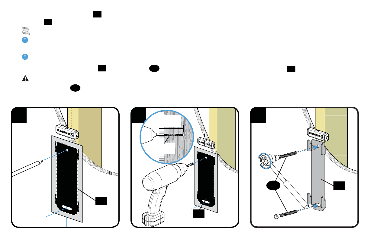
4 5
6
63.5 mm
(2 1/2 in.)
3 mm
(1/8 in.)
17
17
18
4. Place the wall plate template
17
at your desired height and position the slotted holes over your stud center line. Level the wall plate
template
17
and tape in place.
NOTE: For assistance in determining wall plate location, see HeightFinder at sanus.com.
IMPORTANT: Be sure you mark and drill into the center of the stud.
5. Drill the two pilot holes using a 3 mm (1/8 in.) diameter drill bit.
IMPORTANT: Pilot holes must be drilled to a depth of 63.5 mm (2½ in.).
6. Remove the wall plate template
17
. Tighten lag bolts
20
only until they are pulled fi rmly against the wall plate
18
.
CAUTION: Improper use could reduce the holding power of the lag bolt. To avoid potential injuries or property damage do not over-
tighten the lag bolts
20
.
20
11
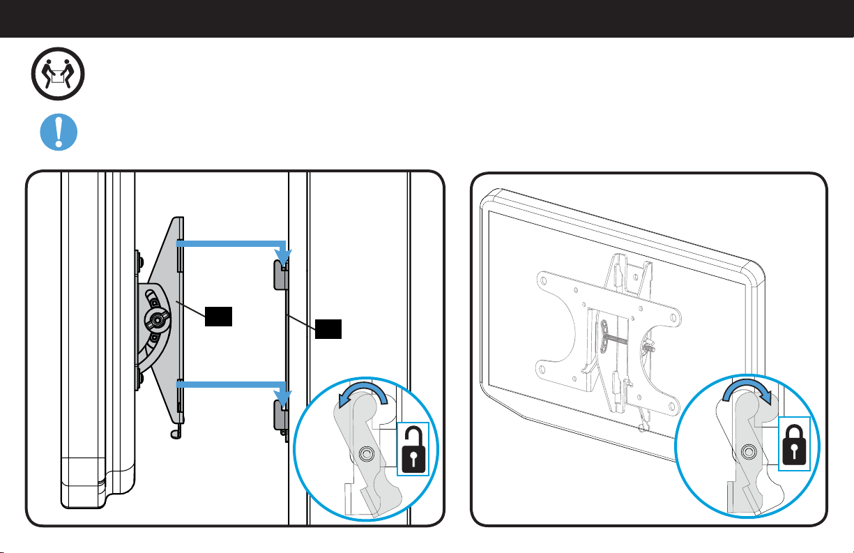
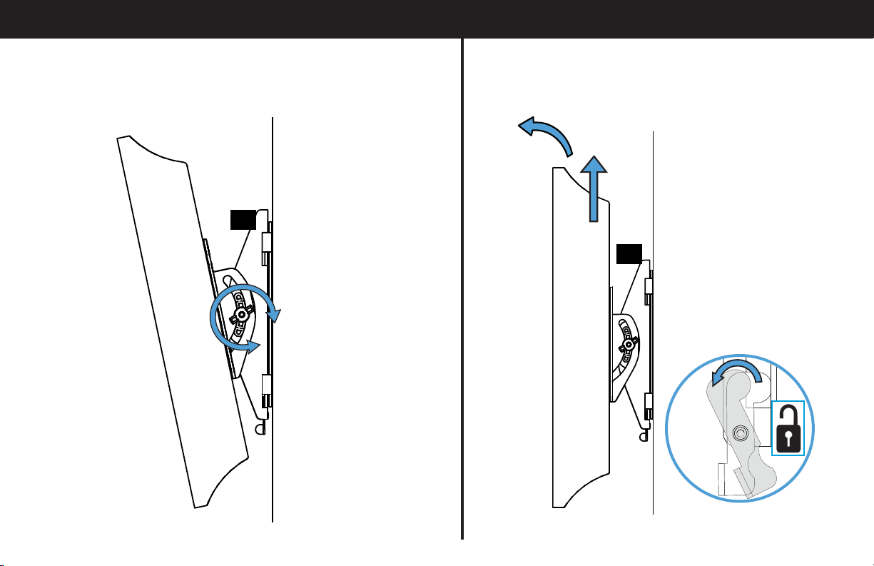
STEP 3 Attach TV to Wall Plate
18
01
HEAVY! You may need assistance with this step.
IMPORTANT: The locking tab needs to be in the unlocked position before attaching the TV to the wall plate.
Once the TV is on the wall plate, the locking tab needs to be in the locked position.
12
Troubleshooting
ADJUSTING THE TILT: Loosen the knob on the TV bracket to adjust
the tilt of your TV. Tighten the knob when your TV is set to the
desired tilt.
REMOVING THE TV: Place the locking tab into the unlocked
position and lift the TV up and out away from the wall plate.
01
01
13
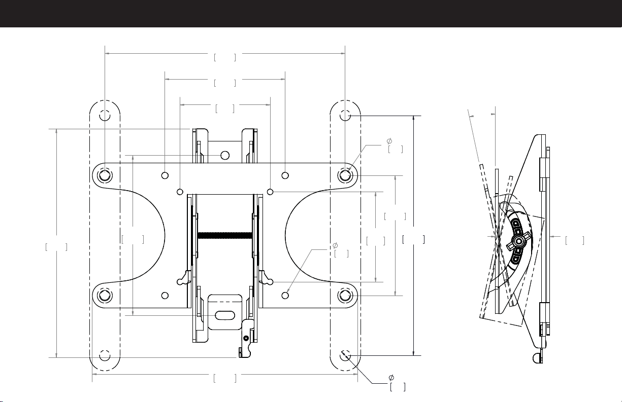
Dimensions
12°
1.78
45.2
7.87
200.0
0.35
8.8
7.87
200.0
3.94
100.0
3.94
100.0
7.50
190.5
0.34
8.8
0.22
5.5
8.69
220.7
2.95
75.0
2.95
75.0
5.25
133.3
14
ESPAÑOL
INSTRUCCIONES DE SEGURIDAD IMPORTANTES. CONSÉRVELAS. LEA TODO EL MANUAL ANTES DE UTILIZAR ESTE PRODUCTO.
Antes de comenzar, verifiquemos que este soporte sea perfecto para usted.
2
¿De qué está hecha su pared?
3
¿Tiene todas las herramientas necesarias?
4
¿Listo para comenzar?
Lea estas instrucciones en su totalidad para estar seguro de sentirse cómodo con este fácil proceso de instalación. Consulte también el
manual del usuario de su televisor para ver si existe algún requisito especial para instalar su televisor en la pared.
Si no entiende las instrucciones o si tiene dudas acerca de la seguridad de la instalación, del ensamblado o del uso del producto,
contáctese con el servicio de atención al cliente al 1-800-359-5520 (Reino Unido: 0800-056-2853).
1
¿Su televisor pesa más de 22.7 kg (50 libras) incluyendo los accesorios?
No — ¡Perfecto!
Sí — Este soporte NO es compatible. Visite MountFinder.Sanus.com o llame al 1-800-359-5520 (Reino Unido: 0800-056-2853) para
encontrar un soporte compatible.
?
Tabiques de yeso con
montantes de madera
¡Perfecto!
¿No está seguro?
Llame al 1-800-359-5520 (Reino Unido: 0800-056-2853)
50 libras
(22.7 kg)
12 mm
(7/16'')
10 mm
(3/8'')
3 mm
(1/8”)
Madera
15
ESPAÑOL
PASO 1 Fijar la placa de sujeción al televisor
Piezas y elementos de sujeción para el PASO 1
NOTA: No todos los accesorios incluidos deberán utilizarse.
ADVERTENCIA: Este producto contiene piezas pequeñas que, si fuesen tragadas, podrían producir asfixia. Antes de iniciar el ensamblaje,
compruebe que todas las piezas estén incluidas y en buenas condiciones. Si faltan piezas o alguna está dañada, no devuelva el artículo al
distribuidor; póngase en contacto con el servicio de atención al cliente. Nunca utilice piezas deterioradas.
1-1 Seleccione los tornillos para el televisor
Enrosque manualmente los tornillos en los encastres roscados del dorso del televisor a fin de determinar qué diámetro de tornillos
(M4, M6 o M8) utilizar.
1-2 Espaciadores
PRECAUCIÓN: Verifique que la combinación de tornillo y espaciador enrosque correctamente en su televisor.
Si el tornillo es demasiado corto, no sostendrá el televisor. Si es demasiado largo, dañará el televisor.
1-3 Mida el patrón de orificios de su televisor
1-4 Instale las extensiones (SOLAMENTE 200 x 200 mm)
El tipo de televisor le ayudará a determinar la configuración de elementos de sujeción que debe utilizar. Compruebe la configuración de
elementos de sujeción recomendada para su tipo de televisor en la página siguiente.
A. Opción de instalación sin espaciadores (televisores con dorso plano).
B. Opción de instalación con espaciadores (televisores con parte posterior con obstrucciones u orificios de montaje intercalados).
Mida en mm el ancho y el alto del patrón de orificios del televisor. Anote las medidas:
x Alto
Ancho
mm mm
Si va a instalar en un televisor con un patrón de orificios de 200 x 200 mm (7.87 x 7.87 pulgadas), incorpore las placas de extensión
02
a la placa
de sujeción para el televisor
01
usando los tornillos
03
y tuercas
04
para placas de extensión.
NOTA: Las tuercas
04
son del tipo Poly-lock y deberán ajustarse con fuerza.
*Es posible que necesite separar la placa de sujeción del televisor
01
de la placa mural
18
antes de comenzar este paso.

16
ESPAÑOL
PASO 2 Fijar la placa mural a la pared
ADVERTENCIA: Este producto contiene piezas pequeñas que, si fuesen tragadas, podrían producir asfixia.
Antes de iniciar el ensamblaje, compruebe que todas las piezas estén incluidas y en buenas condiciones. Si faltan piezas o alguna está dañada,
no devuelva el artículo al distribuidor; póngase en contacto con el servicio de atención al cliente. Nunca utilice piezas deterioradas.
Piezas y elementos de sujeción para el PASO 1
Ubique la placa de sujeción
01
sobre el patrón de orificios del televisor e instálela usando la selección de tornillo, arandela y espaciador (si fuera
necesario) que seleccionó para su televisor.
1-5 Coloque la placa de sujeción
NOTA: Si el patrón de orificios de su televisor de es 75 x 75 mm
15
no deberá utilizar la arandela.
17
PASO 2A
Opción para montantes de madera
ESPAÑOL
* ADVERTENCIA: Este producto contiene un imán. Si utiliza un dispositivo médico implantado como un marcapasos o un desfibrilador automático
implantable (DAI), los campos magnéticos pueden afectar el funcionamiento de esos dispositivos, y causar heridas de gravedad o la muerte. Si tiene
un dispositivo médico implantado, mantenga una distancia de al menos 13 cm (5 pulgadas) entre su dispositivo y el imán. Consulte a su médico antes
de utilizar este producto.
PRECAUCIÓN: Evite lesiones y daños materiales.
● El yeso que recubre la pared no debe exceder los 16 mm (5/8'').
● Tamaño mínimo del montante de madera: común 51 mm x 102 mm (2 x 4 pulgadas), nominal 38 mm x 89 mm (1½ x 3½ pulgadas).
● Debe verificarse el centro del montante
NOTA: Consulte el documento Introducción del detector de montantes magnético Sanus* que se encuentra en la carpeta de
Bienvenida para obtener más información sobre la operación del detector de montantes.
1. Localice un clavo/tornillo en el montante usando el detector de montantes magnético Sanus
19
suministrado.
2. Encuentre los bordes del montante usando la sonda del detector de montantes
19
.
3. Marque el centro del montante con un lápiz.
4. Coloque la plantilla de placa mural
17
a la altura deseada y y posicione los orificios muescados sobre la línea del centro del
montante. Nivele la plantilla de placa mural
17
y fíjela con cinta adhesiva en el lugar.
NOTA: Si necesita ayuda para determinar la ubicación de la placa mural, utilice la herramienta HeightFinder disponible en sanus.com.
IMPORTANTE: Asegúrese de marcar y perforar el centro del montante.
5. Con una mecha de 3 mm (1/8'') de diámetro, realice dos orificios guía.
IMPORTANTE: Los orificios deben realizarse hasta una profundidad de 63.5 mm (2.5'').
6. Retire la plantilla de placa mural
17
. Ajuste los tornillos tirafondo
20
solamente hasta que queden firmes contra la placa mural
18
.
PRECAUCIÓN: El uso indebido podría reducir la capacidad de retención de los tornillos tirafondo. Para evitar lesiones y daños
materiales: no ajuste en exceso los tornillos tirafondo
20
.

18
ESPAÑOL
PASO 3 Fijar el televisor a la placa mural
Dimensiones
¡ELEMENTO PESADO! Es posible que necesite ayuda en este paso.
IMPORTANTE: La pestaña de bloqueo debe estar en la posición abierta antes de fijar el televisor a la placa mural.
Una vez que el televisor se encuentra en la placa mural, debe llevar la pestaña de bloqueo a la posición de bloqueo.
Resolución de problemas
AJUSTE DE LA INCLINACIÓN: Afloje la perilla que se encuentra
en la placa de sujeción del televisor a fin de ajustar la inclinación
de su televisor. Ajuste la perilla cuando su televisor tenga la
inclinación deseada.
EXTRACCIÓN DEL TELEVISOR: Lleve la pestaña de bloqueo a
la posición abierta, y luego levante el televisor y retírelo de la
placa mural.

19

6901-002253 00
Milestone AV Technologies and its a liated corporations and subsidiaries (collectively, “Milestone”), intend to make this manual accurate and complete. However,
Milestone makes no claim that the information contained herein covers all details, conditions, or variations. Nor does it provide for every possible contingency in
connection with the installation or use of this product. The information contained in this document is subject to change without notice or obligation of any kind.
Milestone makes no representation of warranty, expressed or implied, regarding the information contained herein. Milestone assumes no responsibility for accuracy,
completeness or su ciency of the information contained in this document.
©2013 Milestone AV Technologies, a Duchossois Group Company. All rights reserved. Sanus is a division of Milestone.
All other brand names or marks are used for identifi cation purposes and are trademarks of their respective owners.
Thank you for choosing Sanus! Please take a moment to let us know how we did:
SANUS • 6436 City West Parkway • Eden Prairie, MN 55344 USA
Call us: 1-800-359-5520
UK: 0800 056 2853
Email us: [email protected] Leave a review: sanus.com