1. STOP! Read the safety information as noted above.
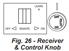
2. Set receiver switch to “ON” position (See Fig. 26).
• When used as a vented decorative appliance, use of the thermostat function is prohibited, operate manually only.
3. Turn control knob clockwise to the “OFF” position (See Fig. 26).
4. Wait five (5) minutes to clear out any gas. Then smell for gas, including near the floor. If you smell gas, STOP! Follow “B” in the safety information as noted above. If you don’t smell gas, go to the next step.
5. Push in slightly and turn control knob counterclockwise to the “PILOT” position (See Fig. 26). Depress control knob.
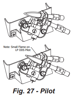
6. With control knob depressed, push down on the ignitor button until the pilot lights. The pilot's location is behind log #3 near the center of the burner. (See Fig. 27).
7. Keep control knob depressed for (30) seconds after pilot lights. Release control knob.
• If the control knob does not pop up when released, stop and immediately call a qualified service technician or gas supplier.
• If pilot goes out repeat steps 3 through 7. Wait (1) minute before attempting to light pilot again. If after several tries the pilot still goes out, turn the gas control knob clockwise to the “OFF” position and call a qualified service technician.
8. Turn control knob counterclockwise to the “ON” position.
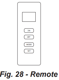
9. To use the included thermostatic remote control, set receiver switch to the “REMOTE” position (See Fig. 28). Press the ON button to turn on the remote to ignite the main burner. Refer to the remote control instruction manual on the next page for “MODE” and “SET” functions.
WARNING: The fireplace screen must be in place while the appliance is in operation.
WARNING: Any glass doors shall be completely opened while appliance is in operation.
TO TURN OFF GAS TO APPLIANCE
1. Set thermostat to the lowest setting.
2. Press the OFF button on the remote control.
3. Push in slightly and turn control knob clockwise to the “OFF” position.
REMOTE CONTROL OPERATION
INTRODUCTION
This remote control system was developed to provide a safe, reliable, and user-friendly remote control system for gas heating appliances. The system is operated manually from the transmitter. The system operates on radio frequencies (RF) within a 20-feet range using non-directional signals. The system operates on one of 1,048,576 security codes that are programmed into the transmitter at the factory; the remote receiver's code must be matched to that of the transmitter prior to initial use.
Review COMMUNICATION SAFETY under GENERAL INFORMATION section. This safety feature shuts down the appliance when a potentially unsafe condition exists.
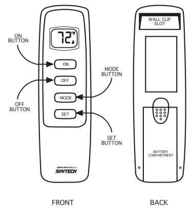
TRANSMITTER
This remote control SYSTEM offers the user a battery-operated remote control to power a latching solenoid such as those used with gas valves used in some heater rated gas logs, gas fireplaces and other gas heating appliances.
The solenoid circuit uses the battery power from the receiver to operate a solenoid. The circuit has reversing polarity software which reverses the positive (+) and negative (-) output of the receiver's battery power to drive a latching solenoid ON/OFF. The SYSTEM is controlled by the remote transmitter.
The transmitter operates on a (2) 1.5V AAA batteries.
ALKALINE batteries should always be used for longer battery life and maximum operational performance. Re-chargeable batteries should not be used.
Before using the transmitter, install the (2) AAA transmitter batteries into the battery compartment. (Use caution that batteries are installed in the proper direction)
KEY SETTINGS
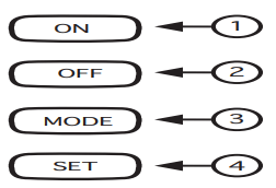
ON - Operates unit to on position, Manually operated solenoid ON.
OFF - Operates unit to off position, Manually operated solenoid OFF.
MODE - Changes unit from manual mode to thermo mode.
SET - Sets temperature in thermo mode.
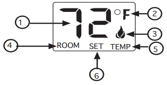
LCD - Liquid Crystal Display
1. DISPLAY Indicates CURRENT room temperature . 2. °F OR °C Indicates degrees Fahrenheit or Celsius. 3. FLAME Indicates burner/valve in operation. 4. ROOM Indicates remote is in THERMO operation. 5. TEMP Appears during manual operation. 6. SET Appears during time the of setting the desired temperature in the thermo operation.
SETTING °F/°C SCALE
The factory setting for temperature is °F. To change this setting to °C, first
• Press the ON key and the OFF key on the transmitter at the same time this will change from °F to °C. Follow this same procedure to change from °C back to °F.
MANUAL FUNCTION
To operate the system in the manual “MODE” do the following.
ON OPERATION
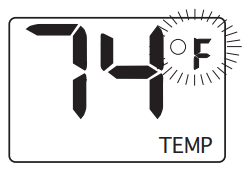
Press the ON key the appliance flame will come on. During this time the LCD screen will show ON, after 3 seconds the LCD screen will default to display room temperature and the word TEMP will show. (Flame icon wil appear on LCD screen in manual on mode)
OFF OPERATION
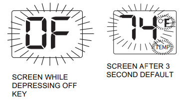
Press the OFF key the appliance flame will shut off. During this time the LCD screen will show OF, after 3 seconds the LCD screen will default to display room temperature and the word TEMP will show.
THERMOSTAT FUNCTION
SETTING DESIRED ROOM TEMPERATURE
When used as a vented decorative appliance, use of the thermostat function is prohibited, operate manually only.
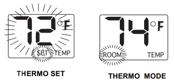
This remote control system can be thermostatically controlled when the transmitter is in the THERMO mode (The word ROOM must be displayed on the screen). To set the THERMO MODE and DESIRED room temperature,
Press the MODE key until the LCD screen shows the word ROOM, then the remote is in the thermostatic mode.
Press and hold the SET key until the desired set temperature is reached. (By pressing and holding the set key the LCD screen set numbers will increase from 45° to 99° then restart over at 45°) Next release the SET key. The LCD screen will display the set temperature for 3 seconds and the LCD screen will flash the set temperature for 3 seconds, then the LCD screen will default to display the room temperature.
TO CHANGE THE SET TEMPERATURE
Press and hold the SET key until the desired set temperature is reached. (By pressing and holding the set key the LCD screen set numbers will increase from 45° to 99° then restart over at 45° ) Next release the SET key. The LCD screen will display the set temperature for 3 seconds, then will flash the set temperature for 3 seconds, then the LCD screen will default to display the room temperature.
Press the MODE key to disengage the thermo mode. The word ROOM on the LCD screen will not show when the thermo is not in operation.
NOTE: The highest SET temperature is 99° Fahrenheit (32° Celsius) and the lowest temperature is (45° Fahrenheit (6° Celsius)
OPERATIONAL NOTES:
The Thermo Feature on the transmitter operates the appliance whenever the ROOM TEMPERATURE varies a certain number of degrees from the SET TEMPERATURE. This variation is called the “SWING” or TEMPERATURE DIFFERENTIAL. The normal operating cycle of an appliance may be 2-4 times per hour depending on how well the room or home is insulated from the cold or drafts. The factory setting for the “swing number” is 2. This represents a temperature variation of +/- 2°F (1°C) between SET temperature and ROOM temperature, which determines when the fireplace will be activated.
The transmitter has ON and OFF manual functions that are activated by pressing either button on the face of the transmitter. When a button on the transmitter is pressed the word ON or OF will appear on the LCD screen to show while the signal is being sent. Upon initial use, there may be a delay of three seconds before the remote receiver will respond to the transmitter. This is part of the system's design.
POWER SETTING – CON 1001 TH
The electronics in the remote control system have the capability of "powering" two different types of DC-powered components. If any operational problems are noted, contact Customer Service.
The RECEIVER comes from the factory programmed to provide pulse DC voltage (5.5 VDC to 6.3 VDC) to a latching solenoid.
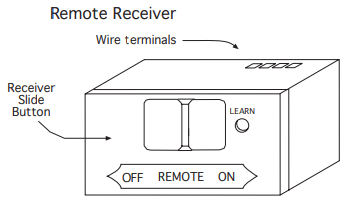
REMOTE RECEIVER
IMPORTANT THE REMOTE RECEIVER SHOULD BE POSITIONED WHERE AMBIENT TEMPERATURES DO NOT EXCEED 130° F.
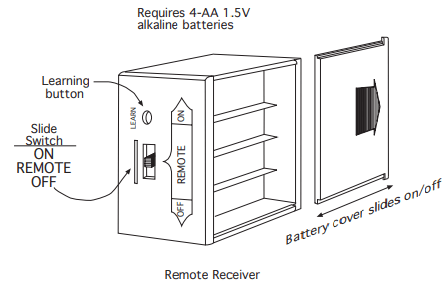
The remote receiver (right) operates on (4) 1.5V AA-size batteries. It is recommended that ALKALINE batteries be used for longer battery life and maximum microprocessor performance. IMPORTANT: New or fully charged batteries are essential to proper operation of the remote receiver as a latching solenoid power consumption is substantially higher than standard remote control systems. Rechargeable batteries should not be used.
NOTE: The remote receiver will only respond to the transmitter when the 3-position slide button on the remote receiver is in the REMOTE position. The remote receiver houses the microprocessor that responds to commands from the transmitter to control system operation.
FUNCTIONS:
With the slide switch in the REMOTE position, the system will only operate if the remote receiver receives commands from the transmitter.
Upon initial use or after an extended period of no use, the ON button may have to be pressed for up to three seconds before activating servo motor. If the system does not respond to the transmitter on initial use, see LEARNING TRANSMITTER TO RECEIVER.
With the slide switch in the ON position you can manually turn ON the system.
With the slide in the OFF position, the system is OFF.
It is suggested that the slide switch be placed in the OFF position if you will be away from your home for an extended period of time.
Placing the slide switch in the OFF position also functions as a safety "lock out" by both turning the system OFF and rendering the transmitter inoperative.
GENERAL INFORMATION
COMMUNICATION – SAFETY – TRANSMITTER – (C/S – TX)
This remote control has a COMMUNICATION –SAFETY function built into its software. It provides an extra margin of safety when the TRANSMITTER is out of the normal 20-foot operating range of the receiver.
The COMMUNICATION – SAFETY feature operates in the following manner, in all OPERATING MODES – ON/ ON THERMO.
At all times and in all OPERATING MODES, the transmitter sends an RF signal every fifteen (15) minutes, to the receiver, indicating that the transmitter is within the normal operating range of 20-feet. Should the receiver NOT receive a transmitter signal every 15 minutes, the IC software, in the RECEIVER, will begin a 2-HOUR (120-minute) countdown timing function. If during this 2-hour period, the receiver does not receive a signal from the transmitter, the receiver will shut down the appliance being controlled by the receiver. The RECEIVER will then emit a series of rapid “beeps” for a period of 10 seconds. Then after 10 seconds of rapid beeping, the RECEIVER will continue to emit a single “beep” every 4 seconds until a transmitter ON or MODE Button is pressed to reset the receiver. The intermittent 4-second beeping will go on for as long as the receiver’s batteries last which could be in excess of one year.
To “reset” the RECEIVER and operate the appliance, you must press the ON or MODE button on the transmitter. By turning the system to ON, the COMMUNICATION -SAFETY operation is overridden and the system will return to normal operation depending on the MODE selected at the transmitter. The COMMUNICATION – SAFETY feature will reactivate should the transmitter be taken out of the normal operating range or should the transmitter’s batteries fail or be removed.
CP (CHILDPROOF) FEATURE
This remote control includes a CHILDPROOF “LOCK-OUT” feature that allows the user to “LOCK-OUT” operation of the appliance, from the TRANSMITTER.
SETTING “LOCK-OUT” –(CP)
To activate the “LOCK-OUT” feature, press and hold the ON button and the MODE button at the same time for 5 seconds. The letters CP will appear in the TEMP frame on the LCD screen.
To disengage the “LOCK-OUT”, press and hold the ON button and the MODE button at the same time for 5 seconds and the letters CP will disappear from the LCD screen and the transmitter will return to its normal operating condition.
To verify that transmitter is in the CP lock-out mode press any key and the LCD screen will show “CP”.
NOTE: If the appliance is already operating in the ON or THERMO MODES, engaging the “LOCK-OUT” will not cancel the operating MODE. Engaging the “LOCK-OUT” prevents only the manual operation of the TRANSMITTER. If in the auto modes, the THERMO operation will continue to operate normally. To totally “LOCK-OUT” the operation of the TRANSMITTER’S operating signals; the transmitter’s MODE must be set to OFF.
LEARNING TRANSMITTER TO RECEIVER
Each transmitter uses a unique security code. It will be necessary to press the LEARN button on the receiver to accept the transmitter security code upon initial use, if batteries are replaced, or if a replacement transmitter is purchased from your dealer or the factory. In order for the receiver to accept the transmitter security code, be sure the slide button on the receiver is in the REMOTE position; the receiver will not LEARN if the slide switch is in the ON or OFF position. The LEARN button in located on the front face of the receiver; inside the small hole labeled LEARN. Using a small screwdriver or end of a paperclip gently press and release the black LEARN button inside the hole. When you release the LEARN button the receiver will emit an audible “beep”. After the receiver emits the beep press the transmitter ANY button and release. The receiver will emit several beeps indicating that the transmitter’s code has been accepted into the receiver.
The microprocessor that controls the security code matching procedure is controlled by a timing function. If you are unsuccessful in matching the security code on the first attempt, wait 1 - 2 minutes before trying again--this delay allows the microprocessor to reset its timer circuitry--and try up to two or three more times.
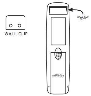
TRANSMITTER WALL CLIP
The transmitter can be hung on a wall using the clip provided. If the clip is installed on a solid wood wall, drill 1/8" pilot holes and install with the screws provided. If it is installed on a plaster/wallboard wall, first drill two 1/4" holes into the wall. Then use a hammer to tap in the two plastic wall anchors flush with the wall; then install the screws provided.
BATTERY LIFE
Replace all batteries regularly. When the transmitter no longer operates the remote receiver from a distance it did previously (i.e., the transmitter's range has decreased) or the remote receiver does not function at all, the batteries should be checked. It is important that the remote receiver batteries are fully charged, providing combined output voltage of at least 5.5volts. The hand held transmitter should operate with as little as 2.5 volts battery power.
TROUBLE SHOOTING
If you encounter problems with your fireplace system, the problem may be the fireplace itself or it could be with the CON1001-TH remote system. Review the fireplace manufacturer's operation manual to make sure all connections are properly made. Then check the operation of the remote in the following manner:
Make sure the batteries are correctly installed in the RECEIVER. One reversed battery will keep receiver from operating properly.
Check battery in TRANSMITTER to ensure contacts are touching (+) and (-) ends of battery. Bend metal contacts in for tighter fit.
Be sure RECEIVER and TRANSMITTER is within 20-feet operating range.
Clear Codes: Memory in the receiver might be full if the learn button is pressed too many times. If this happens it will not allow any more codes to be learned and no audible beep will be heard. To clear memory, place the receiver slide switch into the REMOTE position. Press the learn button and release after 10 seconds. You should hear three (3) long audible beeps indicating all codes have cleared. You can now “learn” the transmitter to the receiver as described in the General Information Section.
Keep RECEIVER from temperatures exceeding 130° F. Battery life shortened when ambient temperatures are above 115° F.
If RECEIVER is installed in tightly enclosed metal surround, the operating distance will be shortened.
Rechargeable batteries should not be used. They do not supply sufficient power to operate the remote system.
CARE AND MAINTENANCE
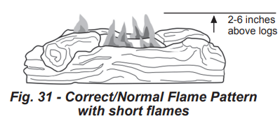
BURNER FLAME PATTERN
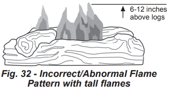
Figure 31 shows a correct burner flame pattern. Figure 32 shows an incorrect burner flame pattern. The incorrect burner flame pattern shows sporadic, irregular flame tipping. The flame should not be dark or have an orange/reddish tinge.
Note: When using the heater the first time, the flame will be orange for approximately one hour until the log cures.
If burner flame pattern is incorrect, as shown in Figure 32.
• turn heater off (see To Turn Off Gas to Appliance, page 24).
• see Troubleshooting, page 34.
WARNING: Turn off heater and let cool before servicing.
CAUTION: You must keep control areas, burner, and circulating air passageways of heater clean. Inspect these areas of heater before each use. Have heater inspected yearly by a qualified service person. Heater may need more frequent cleaning due to excessive lint from carpeting, bedding material, pet hair, etc.
WARNING: Failure to keep the primary air opening(s) of the burner(s) clean may result in sooting and property damage.
BURNER ORIFICE HOLDER AND PILOT AIR INLET HOLE
The primary air inlet holes allow the proper amount of air to mix with the gas. This provides a clean burning flame. Keep these holes clear of dust, dirt, lint and pet hair. Clean these air inlet holes prior to each heating season. Blocked air holes will create soot. We recommend that you clean the unit every three months during operation and have heater inspected yearly by a qualified service person.
We also recommend that you keep the burner tube and pilot assembly clean and free of dust and dirt. To clean these parts we recommend using compressed air no greater than 30 PSI. Your local computer store, hardware store or home center may carry compressed air in a can. If using compressed air in a can, please follow the directions on the can. If you don’t follow directions on the can, you could damage the pilot assembly.
FOR VENTED APPLICATIONS
Periodic examination and cleaning of the venting system and the solid fuel-burning fireplace, including frequency of such examination and cleaning, must be done by a qualified agency.
Shut off unit including pilot. Allow unit to cool for at least 30 minutes.
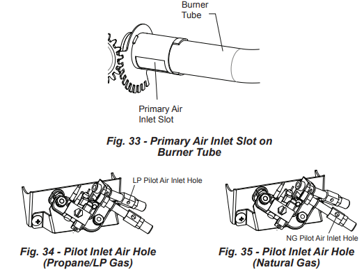
Inspect burner, pilot and primary air inlet holes on orifice holder for dust and dirt (See Fig. 33).
Blow air through the ports/slots and holes in the burner.
Check the orifice holder located at the end of the burner tube again. Remove any large particles of dust, dirt, lint or pet hair with a soft cloth or vacuum cleaner nozzle.
Blow air into the primary air holes on the orifice holder.
In case any large clumps of dust have now been pushed into the burner repeat steps 3 and 4.
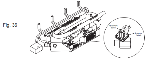
Clean the pilot assembly also. A yellow tip on the pilot flame indicates dust and dirt in the pilot assembly. There is a small pilot air inlet hole about 2" from where the pilot flame comes out of the pilot assembly (see Figures 34 or 35 depending on model). With the unit off, lightly blow air through the air inlet hole. You may blow through a drinking straw if compressed air is not available.
LOG SET
If you remove the log set for cleaning, refer to page 21, for placement instructions.
Replace log set if broken or chipped (dime sized or larger).
CABINET
Air Passageways
Use a vacuum cleaner or pressurized air to clean.
Exterior
Use a soft cloth dampened with a mild soap and water mixture. Wipe the cabinet to remove dust.
TROUBLESHOOTING
WARNING: If you smell gas:
Shut off gas supply.
Do not try to light any appliance.
Do not touch any electrical switch; do not use any phone in your building.
Immediately call your gas supplier from a neighbor’s phone. Follow the gas supplier’s instructions.
If you cannot reach your gas supplier, call the fire department.
IMPORTANT: Operating heater where impurities in air exist may create odors. Cleaning supplies, paint, paint remover, cigarette smoke, cements and glues, new carpet or textiles, etc., create fumes. These fumes may mix with combustion air and create odors.
WARNING: Make sure that power is turned off before proceeding.
WARNING: Turn off and let cool before servicing. Only a qualified service person should service and repair heater.
CAUTION: Never use a wire, needle, or similar object to clean ODS/pilot. This can damage ODS/ pilot unit.
SERVICE HINTS
When Gas Pressure Is Too Low
• pilot will not stay lit
• burners will have delayed ignition
• heater will not produce specified heat
• for propane/LP units, propane/LP gas supply may be low
You may feel your gas pressure is too low. If so, contact your local natural or propane/LP gas supplier.
PROBLEM
POSSIBLE CAUSE
CORRECTIVE ACTION
There is a sputtering sound coming from the Liquid Propane pilot that is a nuisance. When operating on Natural Gas (NG) and the NG pilot is lit.
1. Use of Natural Gas.
1. Call Customer Service.
When ignitor button is pressed in, there is no spark at ODS/ pilot.
1. Ignitor electrode is positioned wrong. 2. Ignitor electrode is broken. 3. Ignitor electrode is not connected to ignitor cable. 4. Ignitor cable is pinched or wet. 5. Damaged ignitor cable. 6. Bad piezo ignitor. 7. Bad Battery.
1. Replace electrode. 2. Replace electrode. 3. Replace ignitor cable 4. Free ignitor cable if pinched by any metal or tubing. Keep ignitor cable dry. 5. Replace ignitor cable. 6. Replace piezo ignitor. 7. Check Battery and replace if needed.
When ignitor button is pressed in, there is a spark at ODS/ pilot but no ignition.
1. Gas supply is turned off or equipment shutoff valve is closed. 2. Control knob not fully pressed in while pressing ignitor button. 3. Air in gas lines when installed. 4. ODS / pilot is clogged. 5. Gas regulator setting is not correct. 6. Control knob not in PILOT position. 7. Depleted gas supply (propane)
1. Turn on gas supply or open equipment shutoff valve. 2. Fully press in control knob while pressing ignitor button. 3. Continue holding down control knob. Repeat igniting operation until air is removed. 4. Clean ODS/pilot (see Care and Maintenance, page 25 & 26) or replace ODS/pilot assembly. 5. Replace gas regulator. 6. Turn control knob to PILOT position. 7. Contact local propane/LP gas company
ODS/pilot lights but flame goes out when control knob is released.
1. Control knob is not fully pressed in. 2. Control knob is not pressed in long enough. 3. Equipment shutoff valve is not fully open. 4. Thermocouple connection is loose. 5. Thermocouple damaged. 6. Control valve damaged. 7. Wrong gas setting. 8. Gas inlet pressure is too high.
1. Press in control knob fully. 2. After ODS/pilot lights, keep control knob pressed in 30 seconds. 3. Fully open equipment shutoff valve. 4. Hand tighten until snug, and then tighten ¼ turn more. 5. Replace thermocouple. 6. Contact customer service. 7. Correct gas selection. 8. Adjust pressure switch (See page 37 for instructions).
Burner(s) does not light afterODS/pilot is lit
1. Burner orifice is clogged. 2. Burner orifice diameter is too small. 3. Inlet gas pressure is too low.
1. Clean burner orifice (see Care and Maintenance, page 25 & 26) or contact customer service. 2. Contact customer service. 3. Contact your gas supplier.
Burner(s) does not light afterODS/pilot is lit. (Heater is set up for NG.)
1. Inlet gas pressure is too high.
1. Contact your gas supplier.
Delayed ignition of burner(s).
1. Manifold pressure is too low. 2. Burner orifice is clogged.
1. Contact your gas supplier. 2. Clean burner (see Care and Maintenance, page 25 & 26) or contact customer service.
Burner backfiring during combustion.
1. Burner orifice is clogged or damaged. 2. Burner is damaged. 3. Gas regulator is damaged.
1. Clean burner orifice (see Care and Maintenance, page 25 & 26 or contact customer service. 2. Contact dealer or customer service. 3. Replace gas regulator.
High yellow flame during burner combustion
1. Not enough air. 2. Gas regulator is defective. 3. Inlet gas pressure is too low.
1. Check burner for dirt and debris. If found, clean burner (see Care and Maintenance, page 25 & 26). 2. Replace gas regulator. 3. Contact your gas supplier.
Gas odor during combustion.
1. Foreign matter between control valve and burner. 2. Gas leak. (See Warning Statement at top of page 27).
1. Take apart gas tubing and remove foreign matter. 2. Locate and correct all leaks (see “Checking Gas Connections,” page 19).
Heater produces a clicking/ticking noise just after burner is lit or shut off.
1. Metal is expanding while heating or contracting while cooling.
1. This is common with most heaters. If noise is excessive, contact qualified service technician.
White powder residue forming within burner box or on adjacent walls or furniture.
1. When heated, the vapors from furniture polish, wax, carpet cleaners, etc., turn into white powder residue.
1. Turn heater off when using furniture polish, wax, carpet cleaner or similar products.
Heater produces unwanted odors.
1. Heater is burning vapors from paint, hair spray, glues, etc. See IMPORTANT statement, page 27. 2. Gas leak. See Warning Statement, page 27. 3. Low fuel supply.
1. Ventilate room. Stop using odor causing products while heater is running. 2. Locate and correct all leaks (see “Checking Gas Connections,” page 19). 3. Refill supply tank (Propane /LP models).
Heater shuts off in use (ODS operates).
1. Not enough fresh air is available. 2. Low line pressure. 3. ODS/pilot is partially clogged. 4. Gas inlet pressure is too high.
1. Open window and/or door for ventilation. 2. Contact local gas supplier. 3. Clean ODS/pilot (see Care and Maintenance, page 25 & 26). 4. Adjust pressure switch (See page 37 for instructions).
Gas odor exists even when control knob is in OFF position.
1. Gas leak. See Warning Statement at top of page 27. 2. Control valve is defective.
1. Locate and correct all leaks (see “Checking Gas Connections”, page 19). 2. Contact customer service.
Moisture/condensation noticed on windows.
1. Not enough combustion/ ventilation air.
1. Refer to “Air for Combustion and Ventilation” requirements, page 9.
Slight smoke or odor during initial operation
1. Residues from manufacturing process.
1. Problem will stop after a few hours of operation.
Heater produces a whistling noise when burner is lit.
1. Turning control knob to high (5) position when burner is cold. 2. Air in gas line. 3. Air passageways on heater are blocked. 4. Dirty or partially clogged burner orifice.
1. Turn control knob to low (1) position and let warm up for a minute. 2. Operate burner until air is removed from line. Have gas line checked by local propane/LP gas company. 3. Observe minimum installation clearances (Fig. 5,6,7,8 page 13-14). 4. Clean burner (see Care and Maintenance, page 25 & 26) or contact customer service.
TROUBLESHOOTING - PRESSURE SWITCH SET POINT ADJUSTMENT:
QUALIFIED INSTALLING AGENCY
Only a qualified agency should perform installation and replacement of gas piping, gas utilization equipment or accessories, and repair and servicing of equipment. The term “qualified agency” means any individual, firm, corporation, or company that either in person or through a representative is engaged in and is responsible for:
a) Installing, testing, or replacing gas piping or
b) Connecting, installing, testing, repairing, or servicing equipment; that is experienced in such work; that is familiar with all precautions required; and that has complied with all the requirements of the authority having jurisdiction.
PRESSURE SWITCH SET POINT ADJUSTMENT:
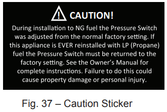
1. Make sure the knob on the Control Valve is in the OFF position, and the switch on the remote receiver (if equipped) is also in the OFF position! Locate the pressure switch on the appliance (Fig 36).
2. Turn OFF the gas at the “Equipment Shut Of Valve”.
3. Turn the Control Valve Knob to the “Pilot” position and Depress the knob for 5 seconds. Return the Control Valve Knob to the “OFF” position. (This step depressurizes the appliance’s internal gas line.)
4. With a Philip's head screw driver turn the adjustment screw on the Pressure Switch clockwise 2 full revolutions (Fig. 36).
5. Turn ON the gas at the “Equipment Shut Of Valve”
6. Light the unit as instructed in the Owner’s Manual or Hang Tags located on the back of the unit and determine if this fixes the pilot outage problem. If the problem persists, turn the Control Valve Knob to the OFF position and repeat Steps 1 through 4 turning the pressure switch adjustment screw one revolution at a time until the appliance functions normally.
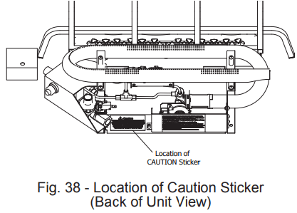
7. When the Pressure Switch set point is adjusted the appliance may not work properly if the unit is ever reinstalled on LP (Propane fuel). The “CAUTION” sticker (Fig. 37) is supplied in the hardware kit. You must install the “CAUTION” sticker on the appliance (Fig. 38).
8. NOTE: If this appliance is ever reinstalled using Propane (LP) fuel the pressure switch adjustment screw should be backed out completely, then reinstalled turning the screw in three full revolutions.
Q: I have a 32000 btu pleasant hearth fireplace. I can light the pilot light but the burner will not light worked good before I unhooked the gas supply to move it to another room now it doesn’t light Reply
Q: can i use the thermat that i seen on computer tha t works on a vfl2-5v024dr Reply
Q: I just purchased this log set, included were packages of lava rock and vermiculite. Since there was not an owners manual or other information about how to use these. When I put small amounts of the vermiculate on the forward burner ports it puts out those flames. What should I do? Thanks! Reply
 to the “OFF” position (See Fig. 26).
  to the “PILOT” position (See Fig. 26). Depress control knob.