This log set has been tested and approved to ANS Z21.11.2 2013 standard for Unvented Heaters and can be operated with the flue damper closed. State and local codes in some areas prohibit the use of vent-free heaters.
INSTALLATION
CHECK GAS TYPE
Make sure your gas supply is correct for your log set. If supply is not correct, do not install heater. Call dealer where you purchased heater for proper gas log set.
Heater CLEARANCES
For convenience and efficiency, install heater
where there is easy access for , inspection and service
in coldest part of room
If this appliance is to be installed directly on carpeting, tile or other combsutible material, other than wood flooring, the appliance must be installed on a metal or wood panel extending the full width and depth of the appliance.
Minimum Clearances For Side Combustible Material, Side Wall and Ceiling
A. Clearances from the side of the heater cabinet to any combustible material and wall should follow diagram in Figure 3.
B. Clearances from the top of the heater opening to the ceiling should not be less than 36".
MINIMUM NONCOMBUSTIBLE MATERIAL CLEARANCE
If Not Using Mantel
You must have noncombustible material(s) above the fireplace opening. Noncombustible materials (such as slate, marble, tile, etc.) must be at least 1/2 in. thick. With sheet metal, you must have noncombustible material behind it, such as a noncombustible fireplace hood accessory. See Fig. 5.
If Using Mantel
You must have noncombustible material(s) (such as slate, marble, tile, etc.) at least 1/2 in. thick.
With sheet metal, you must have noncombustible material behind it. Noncombustible material must extend at least 12 inches up. See Fig. 7.1 for minimum clearances requirements.
MANTEL CLEARANCES
In addition to meeting noncombustible material clearances, you must also meet required clearances between fireplace opening and mantel shelf. If the clearances listed below are not met, you will need to raise the mantel.
Determining Mantel Clearances
If you meet minimum clearance requirements between mantel shelf and top of fireplace opening, your installation (see Fig. 7.1).
FLOOR CLEARANCES
a) If installing appliance on floor level, you must maintain the minimum distance of 14 in. to combustibles (see Fig. 9).
b) If combustible materials are less than 14 in. to the fireplace, you must install appliance at least in. above the combustible flooring (see Fig. 8).
Before beginning assembly or of the product, make sure all parts are present.
Compare parts with package contents list. If any part is missing or damaged, do not attempt to assemble, install or operate the product. Contact customer service for replacement parts.
Estimated Assembly Time: 1 to 2 hours
Tools Required for Assembly (Not Included, unless otherwise stated):
Before installing heater, make sure you have the the following:
Hardware package (provided with heater)
Approved flexible gas hose if allowed by local codes
Sealant (resistant to natural or propane/LP gas)
Electric drill with 3/16- in. drill bit
Phillips screwdriver
External regulator (supplied by installer if required)
Piping (check local codes)
Equipment shutoff valve
Test gauge connection
Sediment trap
Tee joint
Pipe wrench
3/8 NPT to 1/2" flare fitting
Allen Wrench
UNPACKING
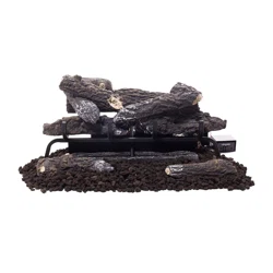
Remove logs, grate, and burner base assembly from carton. NOTE: Do not pick up burner base assembly by burners as this could damage heater. Always handle base assembly by frame.
Remove all protective packaging applied to logs and heater for shipment.
Check all items for any shipping damage. If damaged, promptly inform dealer where you purchased the heater.
GRATE ASSEMBLY PROCEDURE
Position the grate in front of the burner so the 2 legs are pointing downward, the grate ends" that the logs sit on are point- ing upward, and the screw holes line up with the screw holes on the burner unit (See Fig. 11)
Hand tighten the grate to the burner with(2)Attachment Screws, each at an equal distance until hand tightening is no longer possible.
Finish tightening each Attachment Screw with a screw driver, but make sure not to over tighten.
GAS SELECTION INSTRUCTIONS
Convert to natural gas:
Step 1 - Remove access panel
Step 2 - Adjust the gas selector valve
Push in on the selector valve Knob and rotate the knob counter-clockwise until it stops. Release the knob (See Fig. 13)
Do not operate the appliance between locked positions.
Step 3 - Replace Access Panel
Reverse step 2 to convert back to propane gas.
CONNECTING TO GAS SUPPLY
The installer must supply an external regulator for liquid propane. The external regulator is provided by the gas supplier for natural gas. The external regulator will reduce incoming gas pres- sure. You must reduce incoming gas pressure to between 11 and 14 in. of water column for propane and between 6 and 14 in. of water column for natural gas. If you do not reduce incoming gas pres- sure, heater regulator damage could occur. Install external regulator with the vent pointing down as shown in Fig. 15. Pointing the vent down protects it from freezing rain or sleet.
Purchase the optional equipment shutoff valve from your local Home Center store.
Installation Items Needed (Not Provided) • 8'' Adjustable Wrench • 8'' Pipe Wrench • 1/2'' Flexible Gas Line (24'' Min.) or 1/2'' Black Pipe • 90 Deg. 1/2 NPT x 3/8'' Flare Fitting or 3/8 NPT x 1/2 NPT' Street Elbow • Sealant (Resistant to Propane (LP) Gas) • Shut Off Valve • Allen Wrench
1) A variety of options are possible for routing the Gas Connection Lines depending on where your Gas Supply line is located.
NOTICE: Most building codes do not permit concealed gas connections. Check your local build- ing code prior to using a Flexible Gas Line for this installation.
2) Identify the gas inlet on the Heater that corresponds to the fuel type for your installation. Re-move the threaded plug by turning counterclockwise.
Install a 90 degree fitting - not included). Be sure to use a gas resistant sealant on the 3/8 NPT fitting. Position the fitting so the inlet line can be attached without binding. 3) Install the Gas Line to the 90 Deg. fitting and attach to the Shut Off Valve. 4) Check all connections for gas leaks.
CHECKING GAS CONNECTIONS
Pressure Testing Gas Supply Piping System
Test Pressures In Excess Of 1/2 PSIG ( 3.5kPa )
Disconnect heater with its appliance main gas valve (control valve) and equipment shutoff valve from gas supply piping system. Pressures in excess of 1/2 PSIG will damage heater regulator.
Cap off open end of gas pipe where equipment shutoff valve was connected.
Pressurize supply piping system by either using compressed air or opening gas supply tank valve.
Check all joints of gas supply piping system. Apply mixture of liquid soap and water to gas joints. If bubbles form, there may be a leak.
Correct all leaks immediately.
Reconnect heater and equipment shutoff valve to gas supply. Check reconnected fittings for leaks.
Test Pressures Equal To or Less Than 1/2 PSIG (3.5 kPa)
Close equipment shutoff valve (See Fig. 17).
Pressure supply piping system by either using compressed air or opening gas supply tank valve.
Check all joints from gas meter to equipment shutoff valve (See Fig. 18.1 or 18.2). Apply mixture of liquid soap and water to gas joints. If bubbles form, there may be a leak.
Correct all leaks immediately.
Pressure Testing Heater Gas Connections
Open equipment shutoff valve (See Fig. 17).
Open gas supply tank valve.
Make sure control knob of heater is in the OFF position.
Check all joints from equipment shutoff valve to control valve (See Fig. 18.1 or 18.2). Apply mixture of liquid soap and water to gas joints. If bubbles form, there may be a leak.
Light heater (see , page 23). Check all other internal joints for leaks.
Turn off heater (see "To Turn Off Gas to Appliance," page 23).
BEFORE INSTALLING THE APPLIANCE
Turn off gas supply to fireplace or firebox.
Clean fireplace floor and chimney before installing log set. Seal any ash. Clean out doors to protect the unit from down drafts.
MOUNTING PROCEDURE
Place grate/burner assembly into firebox with the front pan facing forward.
Drill two (2) 5/32" diameter holes approximately 1" deep.
Anchor the front pan to the floor using the (2) Concrete Attachment Screws (Not Included) (See Fig. 11.1).
Proper installation of the grate is essential to prevent any movement of the gas logs and controls during .
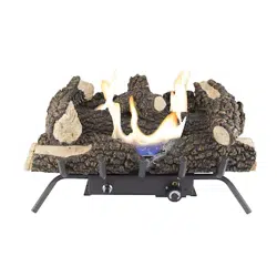
ASSEMBLING LOGS
It is very important to install the logs exactly as instructed. Do not modify logs; use only logs supplied with heater. Each log is marked with a number, and this number will help you identify each log during installation.
1.Insert log #1 onto pins in rear grate base.
2.Insert log #2 onto pins in middle grate base.
3.Place log #3 onto the front grate. Make sure the recessed areas on the log match up with the grate, and the log is centered on grate.
4.Place log #4 so its pin fits into the hole on the top left recessed areas of log #2.
5.Place log #5 so it is resting in the top middle recessed areas of log #1 and its pin fits in the hole on the top of log #2 only (it should NOT be touching log #3), and the front edge does no over hang log #2.
6.Place log #6 so its pin fits in the hole on the top right recessed areas of log #2.
It is very important to install the logs exactly as instructed. Do not modify logs; use only logs supplied with heater. Each log is marked with a number, and this number will help you identify each log during installation.
1.Insert log #1 onto pins in rear grate base.
2.Insert log #2 onto pins in middle grate base.
3.Place log #3 & log #4 onto the front grate. Make sure the recessed areas on the logs match up with the grate, and the logs are centered on grate.
4.Place log #5 so its pin fits into the hole on the top left recessed areas of log #2.
5.Place log #6 so it is resting in the top middle recessed areas of log #1 and its pin fits in the hole on the top of log #2.
6.Place log #7 so its pin fits in the hole on the top right recessed areas of log #2.
OPERATION
FOR YOUR SAFETY READ BEFORE LIGHTING
A. This appliance has a pilot which must be lighted by the electronic ignitor. When lighting the pilot, follow these instructions exactly.
B. BEFORE LIGHTING smell all around the appliance area for gas. Be sure to smell next to the floor because some gas is heavier than air and will settle on the floor.
WHAT TO DO IF YOU SMELL GAS
Do not try to light any appliance.
Do not touch any electrical switch; do not use any phone in your building.
Immediately call your gas supplier from a neighbor’s phone. Follow the gas supplier’s instructions.
If you cannot reach your gas supplier, call the fire department
C. Use only your hand to push in or turn the gas control knob. Never use tools. If the knob will not push in or turn by hand, don’t try to repair it, call a qualified service technician. Forced or attempted repair may result in fire or explosion.
D. Do not use this appliance if any part has been under water. Immediately call a qualified service technician to inspect the appliance and to replace any part of the control system and any gas control which has been under water.
BATTERY INSTRUCTIONS
Batteries are included.
Remove batteries when depleted.
Install/replace the batteries according to the type and quantity stated in table below.
Do not mix old and new batteries. New batteries should be the same brand for best results.
Be sure to observe proper polarity (+/-) when installing or replacing the batteries. Damage due to improper battery installation may void the warranty on the product.
For long periods of non-, remove batteries from all components for safety.
BATTERY INSTALLATION
Locate the Battery Ignitor on the front face of the burner.
Step 2 – Unscrew the cap on the Electronic Push Button ignitor with your fingers by turning it counterclockwise. (Fig. 2)
Insert the battery with the positive (+) side facing forward.
Replace the cap by turning it clockwise until the cap is finger tight.
LIGHTING INSTRUCTIONS
1. STOP! Read the safety information above.
2. Turn control knob clockwise to the “OFF” position (See Fig. 25).
3. Wait five (5) minutes to clear out any gas. Then smell for gas, including near the floor. If you smell gas, STOP! Follow “B” in the safety informa- tion above. If you don’t smell gas, go to the next step.
4. Turn control knob counterclockwise to the “PILOT” position. Depress control knob.
5. With control knob depressed, push down on the ignitor button until the pilot lights. The pilot is located behind the heater screen near the rear of the burner.
• Do not attempt to light the pilot by hand.
6. Keep control knob depressed for (30) seconds after pilot lights. Release control knob.
• If the control knob does not pop up when released, stop and immediately call a qualified service technician or gas supplier.
• If pilot goes out repeat steps 3 through 7. Wait (1) minute before attempting to light pilot again. If after several tries the pilot still goes out, turn the gas control knob clockwise to the “OFF” position and call a qualified service technician.
7. Turn control knob counterclockwise to desired setting.
TO TURN OFF GAS TO APPLIANCE
Turn control knob clockwise to the “OFF” position.
Shutting Off Burner Only (pilot stays lit )
Turn control knob clockwise to the PILOT position.
THERMOSTATIC CONTROL OPERATION
The thermostatic control valve used on this model differs from standard thermostats. Standard ther- mostats simply turn the burner on and off. The thermostat sensing bulb on the control valve used on this heater senses changes in room temperature and will vary the flame accordingly. When the room temperature exceeds the set temperature the burner will shut off completely. The unit will cycle back on as the room temperature drops below the set temperature. The control knob can be set to the de- sired comfort level between 1 and 5.
INSPECTING BURNERS
Check pilot flame pattern and burner flame patterns often.
PILOT FLAME PATTERN
Figure 27 shows a correct pilot flame pattern. Figure 28 shows an incorrect pilot flame pattern. The incorrect pilot flame is not touching the thermocouple. This will cause the thermocouple to cool. When the thermocouple cools, the heater will shut down. If pilot flame pattern is incorrect, as shown in Figure 28.
• turn heater off (see To Turn Off Gas to Appliance, page 23.
• see Troubleshooting, page 27.
CARE AND MAINTENANCE
BURNER FLAME PATTERN
Figure 29 shows a correct burner flame pattern. Figure 30 shows an incorrect burner flame pattern.
The incorrect burner flame pattern shows sporadic, irregular flame tipping. The flame should not be dark or have an orange/reddish tinge.
Note: When using the heater the first time, the flame will be orange for approximately one hour until the log cures.
If burner flame pattern is incorrect, as shown in Figure 30
turn heater off (see To Turn Off Gas to Appliance, page 23).
see Troubleshooting, page 27.
BURNER ORIFICE HOLDER AND PILOT AIR INLET HOLE
The primary air inlet holes allow the proper amount of air to mix with the gas. This provides a clean burning flame. Keep these holes clear of dust, dirt, lint and pet hair. Clean these air inlet holes prior to each heating season. Blocked air holes will create soot. We recommend that you clean the unit every three months during and have heater inspected yearly by a qualified service person. We also recommend that you keep the burner tube and pilot assembly clean and free of dust and dirt. To clean these parts we recommend using compressed air no greater than 30 PSI. Your local computer store, hardware store or home center may carry compressed air in a can. If using compressed air in a can, please follow the directions on the can. If you don’t follow directions on the can, you could damage the pilot assembly.
1. Shut off unit including pilot. Allow unit to cool for at least 30 minutes.
2. Inspect burner, pilot and primary air inlet holes on orifice holder for dust and dirt (See Fig. 31).
3. Blow air through the ports/slots and holes in the burner.
4. Check the orifice holder located at the end of the burner tube again. Remove any large particles of dust, dirt, lint or pet hair with a soft cloth or vacuum cleaner nozzle.
5. Blow air into the primary air holes on the orifice holder.
6. In case any large clumps of dust have now been pushed into the burner repeat steps 3 and 4. Clean the pilot assembly also. A yellow tip on the pilot flame indicates dust and dirt in the pilot assembly. There is a small pilot air inlet hole about 2" from where the pilot flame comes out of the pilot assembly (see Figure 32). With the unit off, lightly blow air through the air inlet hole. You may blow through a drinking straw if compressed air is not available.
TROUBLESHOOTING
SERVICE HINTS
When Gas Pressure Is Too Low
• pilot will not stay lit
• burners will have delayed ignition
• heater will not produce specified heat
• for propane/LP units, propane/LP gas supply may be low
You may feel your gas pressure is too low. If so, contact your local natural or propane/LP gas supplier
PROBLEM
POSSIBLE CAUSE
CORRECTIVE ACTION
There is a sputtering sound coming from the Liquid Propane pilot that is a nuisance. When operating on Natural Gas (NG) and the NG pilot is lit.
1. Use of Natural Gas
1. Call Customer Service.
When ignitor button is pressed in, there is no spark at ODS/ pilot.
1. Ignitor electrode is positioned wrong.
2. Ignitor electrode is broken.
3. Ignitor electrode is not connected to ignitor cable.
4. Ignitor cable is pinched or wet.
5. Damaged ignitor cable.
6. Bad Electronic Push Button ignitor.
7. Bad Battery.
1. Replace electrode.
2. Replace electrode.
3. Replace ignitor cable
4. Free ignitor cable if pinched by any metal or tubing. Keep ignitor cable dry.
5. Replace ignitor cable.
6. Replace Electronic Push Button ignitor.
7. Check Battery and replace if needed.
When ignitor button is pressed in, there is a spark at ODS/ pilot but no ignition.
1. Gas supply is turned off or equipment shutoff valve is closed.
2. Control knob not fully pressed in while pressing ignitor button.
3. Air in gas lines when installed.
4. ODS / pilot is clogged.
5. Gas regulator setting is not correct.
6. Control knob not in PILOT position.
7. Depleted gas supply (propane)
1. Turn on gas supply or open equipment shutoff valve.
2. Fully press in control knob while pressing ignitor button.
3. Continue holding down control knob. Repeat igniting until air is removed.
4. Clean ODS/pilot (see Care and Maintenance, page 25 & 26) or replace ODS/pilot assembly.
5. Replace gas regulator.
6. Turn control knob to PILOT position.
7. Contact local propane/LP gas company
ODS/pilot lights but flame goes out when control knob is released.
1. Control knob is not fully pressed in.
2. Control knob is not pressed in long enough.
3. Equipment shutoff valve is not fully open.
4. Thermocouple connection is loose.
5. Thermocouple damaged.
6. Control valve damaged.
7. Wrong gas setting.
1. Press in control knob fully.
2. After ODS/pilot lights, keep control knob pressed in 30 seconds. 3. Fully open equipment shutoff valve.
4. Hand tighten until snug, and then tighten ¼ turn more.
5. Replace thermocouple.
6. Contact customer service.
7. Correct gas selection.
Burner(s) does not light afterODS/pilot is lit.
1. Burner orifice is clogged.
2. Burner orifice diameter is too small.
3. Inlet gas pressure is too low.
1. Clean burner orifice (see Care and Maintenance, page 25 & 26) or contact customer service.
2. Contact customer service.
3. Contact your gas supplier
Burner(s) does not light afterODS/pilot is lit. (Heater is set up for NG.)
1. Inlet gas pressure is too high.
1. Contact your gas supplier.
Delayed ignition of burner(s).
1. Manifold pressure is too low.
2. Burner orifice is clogged.
1. Contact your gas supplier.
2. Clean burner (see Care and Maintenance, page 25 & 26) or contact customer service.
Burner backfiring during combustion.
1. Burner orifice is clogged or damaged.
2. Burner is damaged.
3. Gas regulator is damaged.
1. Clean burner orifice (see Care and Maintenance, page 25 & 26 or contact customer service.
2. Contact dealer or customer service.
3. Replace gas regulator.
High yellow flame during burner combustion
1. Not enough air.
2. Gas regulator is defective.
3. Inlet gas pressure is too low.
1. Check burner for dirt and debris. If found, clean burner (see Care and Maintenance, page 25 & 26).
2. Replace gas regulator.
3. Contact your gas supplier.
Gas odor during combustion.
1. Foreign matter between control valve and burner. 2. Gas leak. (See Warning Statement at top of page 27).
1. Take apart gas tubing and remove foreign matter.
2. Locate and correct all leaks (see “Checking Gas Connections,” page 19)
Heater produces a clicking/ticking noise just after burner is lit or shut off.
1. Metal is expanding while heating or contracting while cooling.
1. This is common with most heaters. If noise is excessive, contact qualified service technician.
White powder residue forming within burner box or on adjacent walls or furniture.
1. When heated, the vapors from furniture polish, wax, carpet cleaners, etc., turn into white powder residue.
1. Turn heater off when using furniture polish, wax, carpet cleaner or similar products.
Heater produces unwanted odors.
1. Heater is burning vapors from paint, hair spray, glues, etc. See IMPORTANT statement, page 27.
2. Gas leak. See Warning Statement, page 27.
3. Low fuel supply.
1. Ventilate room. Stop using odor causing products while heater is running.
2. Locate and correct all leaks (see “Checking Gas Connections,” page 19).
3. Refill supply tank (Propane /LP models).
Heater shuts off in use (ODS operates).
1. Not enough fresh air is available.
2. Low line pressure.
3. ODS/pilot is partially clogged.
1. Open window and/or door for ventilation.
2. Contact local gas supplier.
3. Clean ODS/pilot (see Care and Maintenance, page 25 & 26).
Gas odor exists even when control knob is in OFF position.
1. Gas leak. See Warning Statement at top of page 27.
2. Control valve is defective.
1. Locate and correct all leaks (see “Checking Gas Connections”, page 19).
2. Contact customer service.
Moisture/condensation noticed on windows.
1. Not enough combustion/ ventilation air.
1. Refer to “Air for Combustion and Ventilation” requirements, page 9.
Slight smoke or odor during initial
1. Residues from manufacturing process.
1. Problem will stop after a few hours of .
Heater produces a whistling noise when burner is lit.
1. Turning control knob to high (5) position when burner is cold.
2. Air in gas line.
3. Air passageways on heater are blocked.
4. Dirty or partially clogged burner orifice.
1. Turn control knob to low (1) position and let warm up for a minute.
2. Operate burner until air is removed from line. Have gas line checked by local propane/LP gas company.
Additionally, the document applies to other Pleasant Hearth models: VFL2-SO18DT, VFL2-EO18DT, VFL2-SO24DT, VFL2-EO24DT, VFL2-WW18DT, VFL2-RW18DT, VFL2-WW24DT


 to the “OFF” position (See Fig. 25).
 to the “PILOT” position. Depress control knob.