Loading ...
Loading ...
Loading ...
8
N
0
519 AUDIO PLAYER / OWNER’S MANUAL
GETTING STARTED
Output Connectors
Balanced output connectors:
these XLR 3-pin connectors
provide a line-level left-channel and right-channel signal that
can be used to send the selected input to preamplifier inputs,
power amplifier inputs, a powered subwoofer, or to recording
components. Mark Levinson recommends using the Balanced
outputs as the primary output if your preamplifier or amplifiers
offer balanced inputs.
Single-ended output connectors:
these RCA connectors provide
a line-level left-channel and right-channel signal that can be
used to send the selected input to preamplifier or amplifier
inputs, a powered subwoofer, to a second listening zone, or to
recording components.
The Balanced and Single-ended outputs can be configured in the
menu as Fixed (for use with a separate preamplifier, recording
components or a second audio zone). When configured as Fixed,
these outputs are not affected by the Volume knob or Mute button.
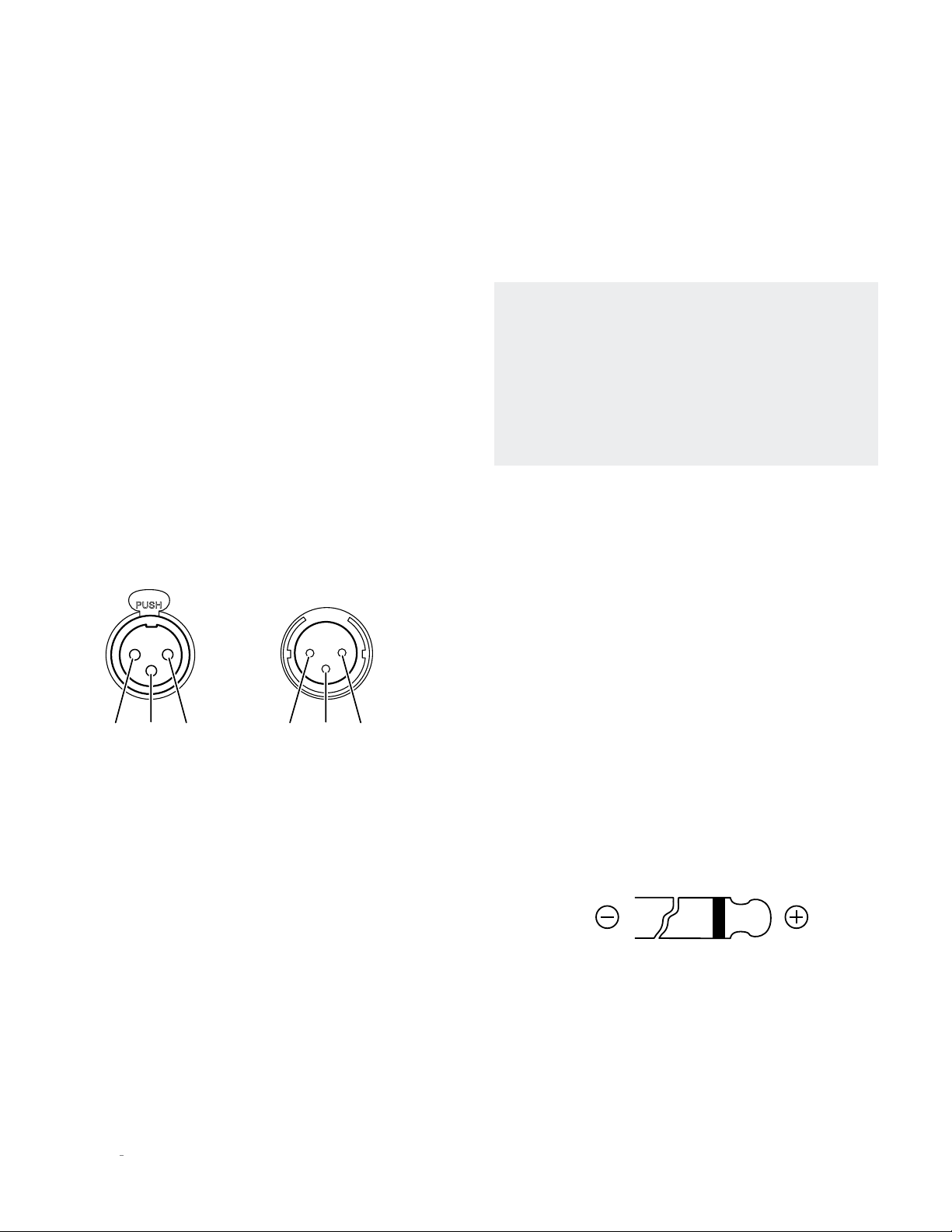
Balanced
Input Connector
(female XLR)
Pin
3
Pin
3
Pin
1
Pin
1
Pin
2
Pin
2
Balanced
Output Connector
(male XLR)
Digital output connectors:
the № 519 has three digital output
connectors: AES/EBU Balanced XLR, Coaxial S/PDIF RCA,
and Optical S/PDIF TOSLINK. Each digital output provides a
two-channel digital connection to your DAC or preamplifier
with built-in DAC. Mark Levinson recommends using the
Balanced digital output for the best possible sound quality if the
connection is available on the DAC or preamplifier to which the
player is connected.
Input Connectors
Digital audio input connectors:
the № 519 has six digital input
connectors:
• One AES/EBU Balanced XLR, numbered 1
• Two Coaxial S/PDIF RCA, numbered 2 and 3
• Two Optical S/PDIF TOSLINK, numbered 4 and 5
• One Asynchronous USB Type B, numbered 6
Mass storage connectors:
Two Mass Storage USB Type A
• These connectors can be used for attaching USB drives
containing music, unit software updates, or setup
configuration importing and exporting.
Please note that the
USB Type A connections are not for direct connection to an
audio source device.
Note: when importing settings or software updates from
a USB flash drive, please remove any other USB drives
attached to the unit first, then insert the one with the new
settings or software.
Note: Mark Levinson recommends using high-quality, name
brand USB drives for the best reliability and performance.
Use of low-quality drives may degrade performance or not
be reliable.
Control Connectors
Ethernet connector:
This connector accepts a Cat5 or higher
cable for connection to an Ethernet network. For information on
how to configure and use the Ethernet port, see the online user
guide.
IR input connector:
this 1/8-inch (3.5mm) connector accepts IR
(infrared) control signals from other equipment. Note that this
connector does not provide power for IR extender modules.
RS-232 connector:
this RJ-11 connector provides serial control
through a standard RS-232 connection.
Trigger output connectors:
these 1/8-inch (3.5mm) TS phone
plug connectors can be used to activate other components in
the audio system and listening room, such as amplifiers, lights,
and window shades. A 12V 100mA DC signal is output whenever
the unit is on. (See illustration)
Trigger phone plug connector pin assignments:
• Tip: +
• Sleeve: –
Trigger input connector:
this 1/8-inch (3.5mm) TS phone plug
connector can be connected to the trigger output of another
system component or control system that supplies a trigger
voltage. Whenever the unit detects a voltage between 5V and
12V DC at this connection, it will turn On from Standby. When
the trigger signal at this connection ceases, the unit will enter
the selected Standby mode. (See illustration)
Loading ...
Loading ...
Loading ...