Loading ...
Loading ...
Loading ...
39
PRODUCT PECIFICATIONS (Continued)
Signal Input
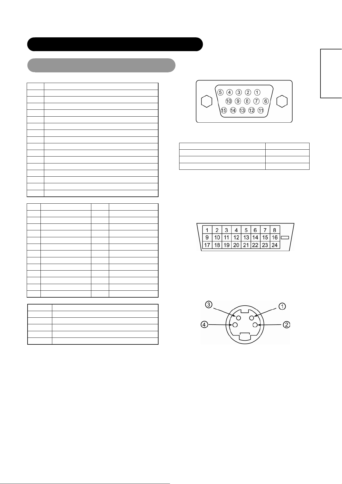
RGB1 Input (D-sub 15-pin connector)
Pin Input signal
1 R
2 G or sync on green
3 B
4 No connection
5 No connection
6 R.GND
7 G.GND
8 B.GND
9 No connection
10 GND
11 No connection
12 [SDA]
13 H. sync or H/V composite sync
14 V.sync. [V.CLK]
15 [SCL]
Frame GND
RGB2 (DVI-D) Input
Pin Input signal Pin Input signal
1 T.M.D.S. Data2- 14 +5V Power
2 T.M.D.S. Data2+ 15 Ground (for+5V)
3 T.M.D.S. Data2/4 Shield 16 Hot Plug Detect
4 T.M.D.S. Data4- 17 T.M.D.S. Data0-
5 T.M.D.S. Data4+ 18 T.M.D.S. Data0+
6 DDC Clock 19 T.M.D.S. Data0/5 Shield
7 DDC Data 20 T.M.D.S. Data5-
8 No Connect 21 T.M.D.S. Data5+
9 T.M.D.S. Data1- 22 T.M.D.S. Clock Shield.
10 T.M.D.S. Data1+ 23 T.M.D.S. Clock+
11 T.M.D.S. Data1/3 Shield 24 T.M.D.S. Clock-
12 T.M.D.S. Data3- Frame GND
13 T.M.D.S. Data3+
S-input connector pin specifications
Pin Input signal
1 Y
2 Y-GND
3 C
4 C-GND
Frame GND
• When different kinds of input signals are simultaneously input to the
monitor via a graphics board or the like, the monitor will automatically
select the signals in the following priority order:
Sync signal type Priority
H/V separate sync. 1
H/V composite sync. 2
sync.on Green * 3
*Even in the case of the recommended signals shown on the following
page, there may be instances when correct display is not possible. In
this case, use H/V separate sync, or H/V composite sync.
ENGLISH
Loading ...
Loading ...