Loading ...
Loading ...
Loading ...
33
Power cord
1
2
3
4
5
6
7
8
9
a
b
c
1 To power supply
2 Power cord
3 Yellow
To terminal supplied with power regardless of ignition switch
position.
4
Red
To electric terminal controlled by ignition switch (12 V DC)
ON/OFF.
5
Orange/white
To lighting switch terminal.
6
Black (ground)
To vehicle (metal) body.
7
Violet/white
Of the two lead wires connected to the back lamp, connect
the one in which the voltage changes when the gear shift
is in the REVERSE (R) position. This connection enables
the unit to sense whether the car is moving forwards or
backwards.
8
Blue/white
Connect to system control terminal of the power amp (max.
300 mA 12 V DC).
9
Light green
Used to detect the ON/OFF status of the parking brake. This
lead must be connected to the power supply side of the
parking brake switch.
a
Power supply side
b Parking brake switch
c Ground side
Parking Brake
1 If “Light green” cable is connected to parking
brake switch, video image on the display will
be controlled by this function.
2 The monitor displays the black screen with
warning information to prevent the driver
watching video contents during driving.
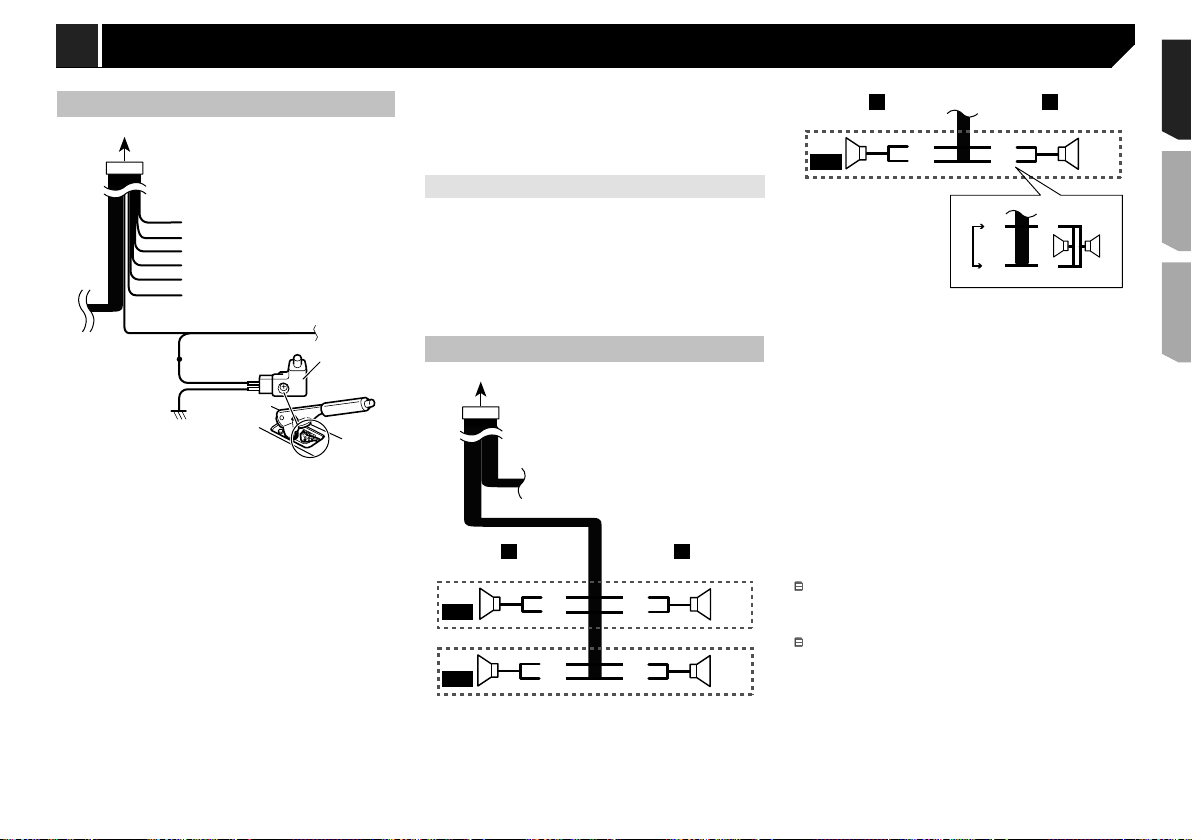
Speaker leads
1
2
9
a
d
e
7
43
5
6
8
b
c
LR
F
R
Perform these connections when using a subwoofer without the
optional amplifier.
d
e
43
f
b
c
LR
SW
b
c
g
e
d
h i
1 To power supply
2 Power cord
3 Left
4 Right
5 Front speaker
6 Rear speaker
7 White
8 White/black
9 Gray
a Gray/black
b Green
c Green/black
d Violet
e Violet/black
f Subwoofer(4Ω)
g Whenusingasubwooferof70W(2Ω),besuretoconnect
the subwoofer to the violet and violet/black leads of this unit.
Do not connect anything to the green and green/black leads.
h
Not used.
i Subwoofer(4Ω)×2
When a subwoofer is connected to this product instead of
a rear speaker, change the rear output setting in the initial
setting. The subwoofer output of this product is monaural.
Switching the rear speaker output on page 26
With a two-speaker system, do not connect anything to the
speaker leads that are not connected to speakers.
Notice for the blue/white lead
When the ignition switch is turned on (ACC ON), a control
signal is output through the blue/white lead. Connect to an
external power amp’s system remote control terminal, the
auto-antenna relay control terminal, or the antenna booster
power control terminal (max. 300 mA 12 V DC). The control
signal is output through the blue/white lead, even if the
audio source is switched off.
This product
1
2
345678
1 Microphone 4 m (13 ft. 1 in.)
(AVH-280BT)
2
This product
3 Antenna jack
4 Wired remote input
Hard-wired remote control adapter can be connected (sold
separately).
5
Power supply
6 Fuse (10 A)
7 Front output
8 Rear output or subwoofer output
33
< QRD3356-A >
Connection Connection
Loading ...
Loading ...
Loading ...