1
ASSEMBLY INSTRUCTIONS
STYLE NO: 606
Read all instructions before use of the
changing table.
KEEP INSTRUCTIONS FOR FUTURE USE.
Use only the pad provided by manufacturer.
Do not use changing table, add-on changing
unit, or countered changing pad if it is
damaged or broken.
Fail Hazard-To prevent death or serious i
njury
, always keep child within arm’s reach.
WARNING
Never leave your child unattended in this
dressing table.To insure the safety of your
child, the restraint system must be used.
Check regularly to see that all bolts are tight.
Clean by wiping with damp clean cloth.
DO NOT use abrasives.
prevent improper use of the units .
1.Attach one of the mounting brackets securely to the back top edge of the furniture using
the short screw .
2.Find the stud in the wall and mark the location on the wall for mounting the second
bracket, with a 2” wood screw , approximately 2” below the bracket mounted to the edge
of the furniture .
3.If a stud cannot be found , purchase a “Hollow-Wall Anchor Bolt” and attach the second
bracket to the wall using that bolt .Make sure to follow all instructions by the manufacturer.
4.Place the furniture so the bracket on the back edge is in line with the bracket on the wall .
5.Lace an end of the nylon restraint strap down through each bracket . Bring both ends
together and slide the beaded end of the strap through the key hole shaped slot in the
other end unit snug . Pull down on the beaded end until it snap locks into the keyhole .
6.Check to make sure the strap is securely laced and locked to the brackets.When child
reaches a maximum weight of 30lbs,the dressing/changing table shall no longer be used.
Please note that the warning sticker is placed on the changer to keep parents and
caregivers informed it is a requirement by law under CPSC and ASTM. We do apologize
for any inconvenience this may cause you.
606
D
Dream On Me Inc.
1532 S WASHINGTON AVE
PISCATAWAY TWP NJ 08854
Email: [email protected]
www.dreamonme.com
Scan the QR code to register your product
https://dreamonme.com/customercare/registration/

Lisez toutes les instructions dans ce guide avant d'utiliser la table à langer.
CONSERVEZ CES INSTRUCTIONS POUR RÉFÉRENCE ULTÉRIEURE.
Ne pas utiliser de matelas autre que celui fourni par le manufacturier.
Ne pas utiliser la table, l'unité additionnelle à langer ou le matelas à langer incurvé s'ils
sont brisés ou endommagés.
Risque de Chute — Pour prévenir des blessures sérieuses ou même la mort, toujours
avoir le bébé à portée de main.
Ne laissez jamais votre bébé sans surveillance sur cette table. Pour assurer la sécurité
de votre bébé il faut utiliser le système de restreintes. Vérifiez régulièrement si tous les
boulons sont serrés.
Nettoyez en essuyant avec un chiffon propre et humide. NE PAS utiliser des produits
abrasifs.
Notez s'il vous plaît que l'avertissement sur la table à langer est exigé par la loi de la
CPSC et l'ASTM, qui nous oblige d'informer les parents et les personnes en charge des
enfants. Nous nous excusons pour toute inconvenance que cela pourrait vous causer.
Les restreintes sont seulement un moyen protecteur. Seule la supervision d'un adulte
est un moyen sûr de sécurité pour prévenir l'utilisation hasardeuse des unités.
1. À l'aide de la vis courte, fixez l'un des supports de fixation sur le bord supérieur en
arrière du meuble.
2. Trouvez le goujon dans le mur et marquez l'emplacement sur le mur, pour faire
installer le deuxième support, avec une vis 2" à bois, environ 2" en dessous du support
qui se trouve monté sur le bord du meuble.
3. Si un goujon ne peut être trouvé, vous devez faire l'achat d'un « dispositif d’ancrage
pour mur creux » et fixer le deuxième support
au mur, à l'aide du boulon. Assurez-vous
de suivre toutes les instructions fournies par le fabricant.
4. Placez le meuble en vous assurant que le support sur le bord arrière est aligné avec
le support sur le mur.
5. Passer l'extrémité de la courroie de rétention en nylon dans chaque attache. En
prenant l'extrémité emboutie de la courroie, passez-la dans la fente en forme de serrure
de l'autre bout en créant un nœud. Tirer sur l'extrémité emboutie jusqu'à ce que le mé-
canisme soit verrouillé dans la fente en forme de serrure.
6. Assurez-vous que la sangle est bien fixée et verrouillée au support de montage. Si
votre enfant atteint le poids maximum de 30lbs, n'utilisez plus la table à langer.
2
MISE EN GARDE
3
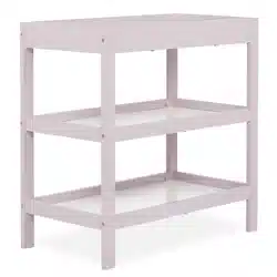
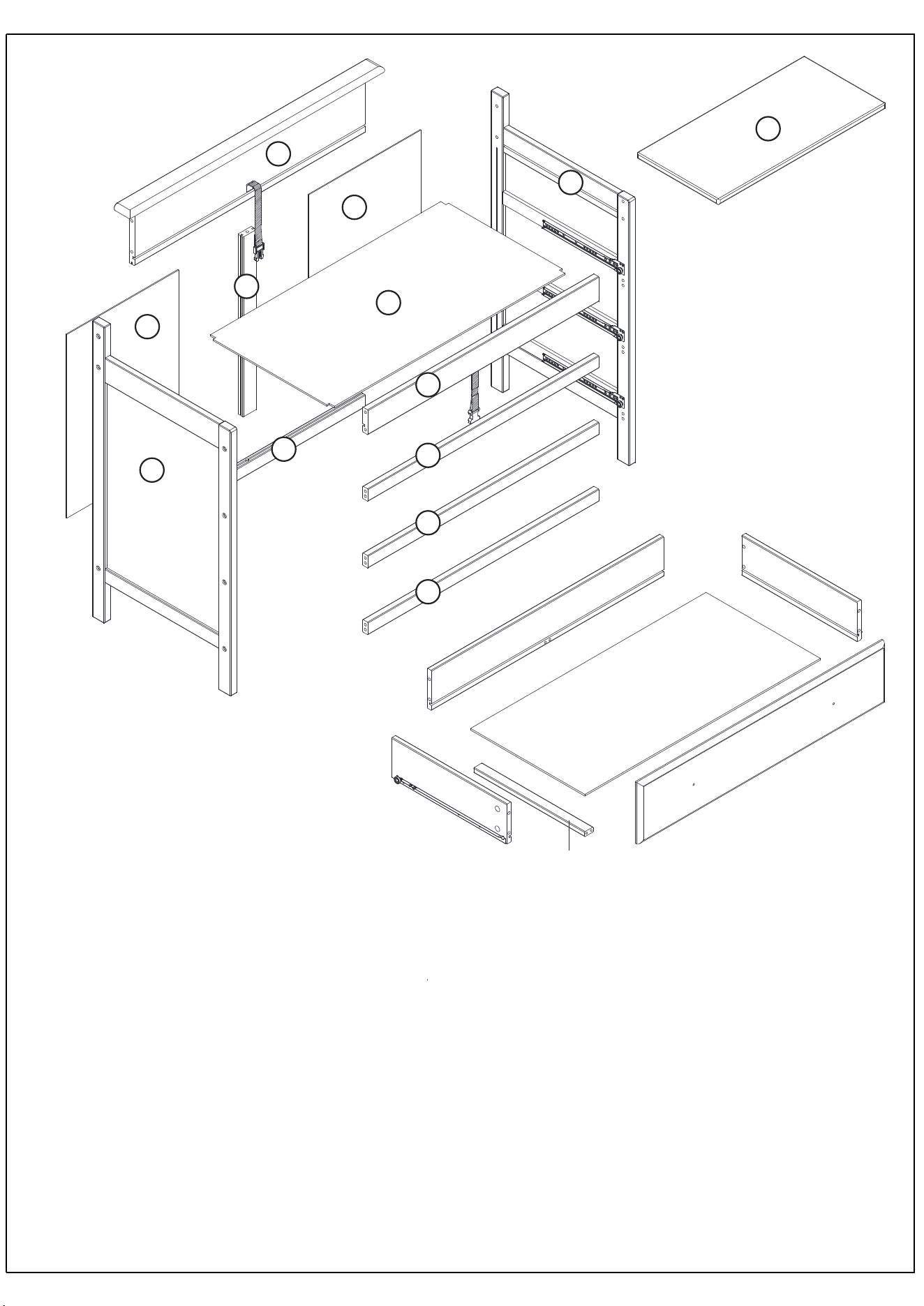
A: Left head board(1pc)
B: Right head board(1pc)
C: Back rail(1pc)
D: Front rail(1pc)
H: Back panel(2pcs)
G: Central back rail (1pc)
K: Pad(1pc)
J: Platform(1pc)
E: Front stabilizer bar(3pcs)
F: Back stabilizer bar(1pc)
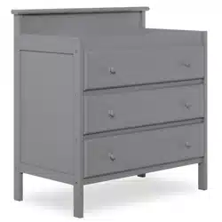
DR1:
Front panel(3pcs)
DR2:
Side panel(6pcs)
DR3: Back panel(3pcs)
DR4:
Bottom panel(3pcs)
DR5:
Bottom support panel (3pcs)
A: Tête de lit gauche (1pc)
B: Tête de lit droite (1pc)
C: Rail avant (1pc)
D: Rail arrière (1pc)
E: Barre stabilisatrice avant (3pcs)
G:
Panneau arrière (2pcs)
H: Rail central arrière (1pc)
K: Matelas (1pc)
J: Plateforme (1pc)
F: Barre stabilisatrice arrière (1pc)
DR1:
Panneau avant (3pcs)
DR2:
Panneau latéral (6pcs)
DR3: Panneau arrière (3pcs)
DR4:
Panneau inférieur (3pcs)
DR5:
Panneau de support
inférieur (3pcs)
A
B
C
J
D
E
E
E
F
G
H
H
DR3
DR4
DR1
DR2.2
DR2.1
DR5
K
Panneau avant (3pcs)
Panneau latéral (6pcs)
Panneau arrière (3pcs)
Panneau inférieur (3pcs)
4
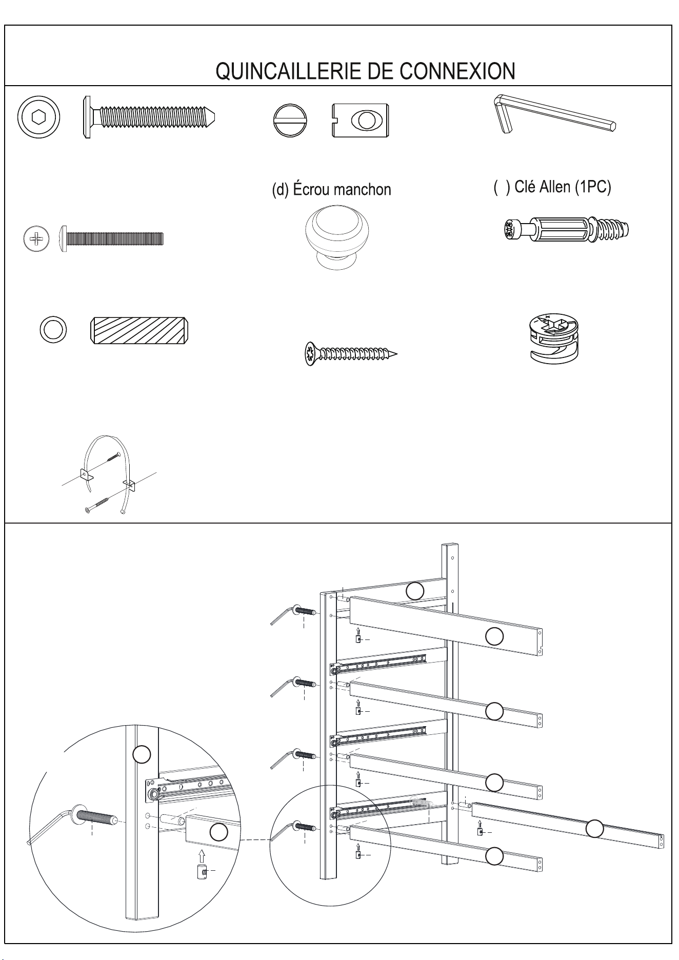
Use allen wrench (c) to connect bolts. Connect front stabilizer bar ( F)and back
stabilizer bar (G ) and
Front rail (D) to Left head board (A)
by using wood dowels (b) and bolts (a).
STEP 1
a
1-1/2” Allen head bolt (18pcs)
ÉTAPE 1
a. Vis à six pans 1-1/2" (18pcs)
À l'aide de la clé Allen (c) faites attacher les
boulons. Attachez la barre stabilisatrice
avant (F) et arrière (G) à la tête de lit droite (B),
en utilisant les goujons en bois (b) et les
boulons (a).
CONNECTION HARDWARE
e. Knob (6pcs)
e . Bouton (6pcs)
d. 1” Knob Screw (6pcs)
Vis de Bouton 1” (6pcs)
(d) Barrel nu t (18PCS)
(18PCS)
(
b
) Wood dowel (16pcs)
Goujon en bois (16pcs)
(
b
)
f
Cam bolts(24pcs)
f.Pênes battants (24pcs)
g
h . 1 - 1 / 2 ” Self-tapping(3pcs)
h . Vis autotaraudeuse
1-1/2" (3pcs)
i . Tip over restraints(1pc)
i . Fixation antibasculement (1pc)
Cams(24pcs)
g. Cames (24pcs)
(c) Allen wrench (1PC)
c
E
E
E
D
F
A
a
b
b
b
b
d
b
a
a
a
d
d
d
d
a
a
d
b
E
A
X 5
Cams(24pcs)
g. Cames (24pcs)
5
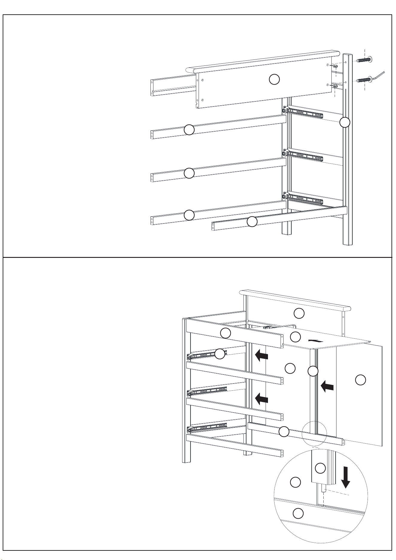
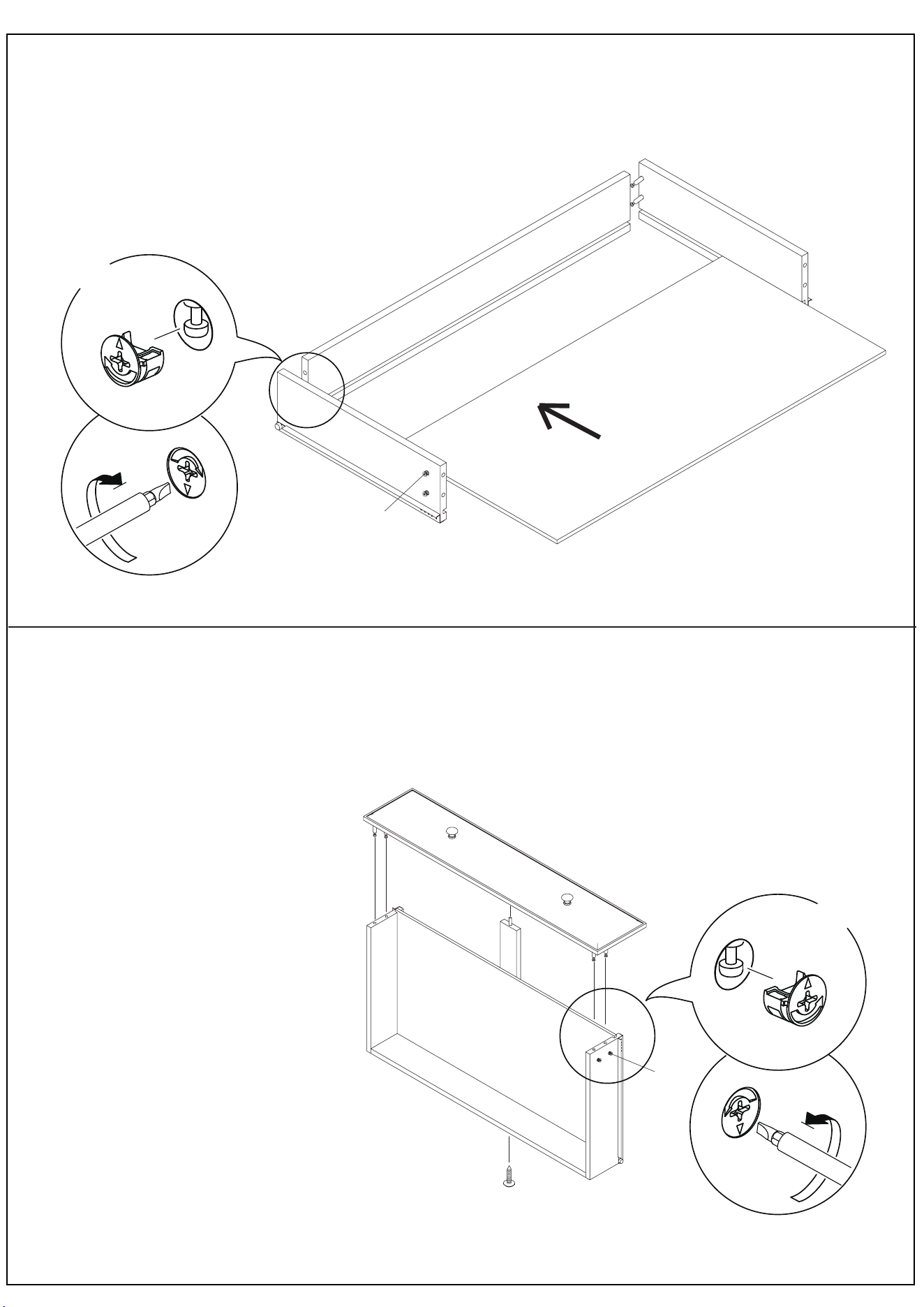
1: Insert one piece of back panel (H) into groove
between back rail (E) and back stabilizer bar (G);
2: Connect central back rail (J) to back rail (E) and back
stabilizer bar (G) by wood dowels (b);
3: Insert second back panel (H).
4: Insert platform (K) into groove between back rail (E)
and front rail (D).
STEP 3
Connect Back rail (C) to Left head board (A) by using barrel nut (d) and 1-1/2 ”bolt (a).
DO NOT fully tighten the bolts.
STEP 2
ÉTAPE 3
ÉTAPE 2
Attachez le goujon supérieur (C), le rail
avant (D) et le rail arrière (E) à la tête de
lit droite (B) en utilisant les
goujons en bois (b) et les
boulons (a).
NE PAS serrer les boulons
à fond.
1 : Placez une partie du panneau arrière (H)
dans la rainure entre le ra-il arrière (E) et la
barre stabilisatrice arrière (G);
2 : Attachez le rail central arrière (J) au rail
arrière (E) et à la barre stabilisatrice arrière
(G) en utilisant des goujons en bois (b);
3 : Insérez le deuxième panneau arrière (H).
4 : Insérez la plateforme (K) dans la rainure
entre le rail arrière (E) et le rail avant (D).
a
d
d
a
C
A
F
E
E
E
C
J
H
H
G
D
A
F
G
b
H
F
6
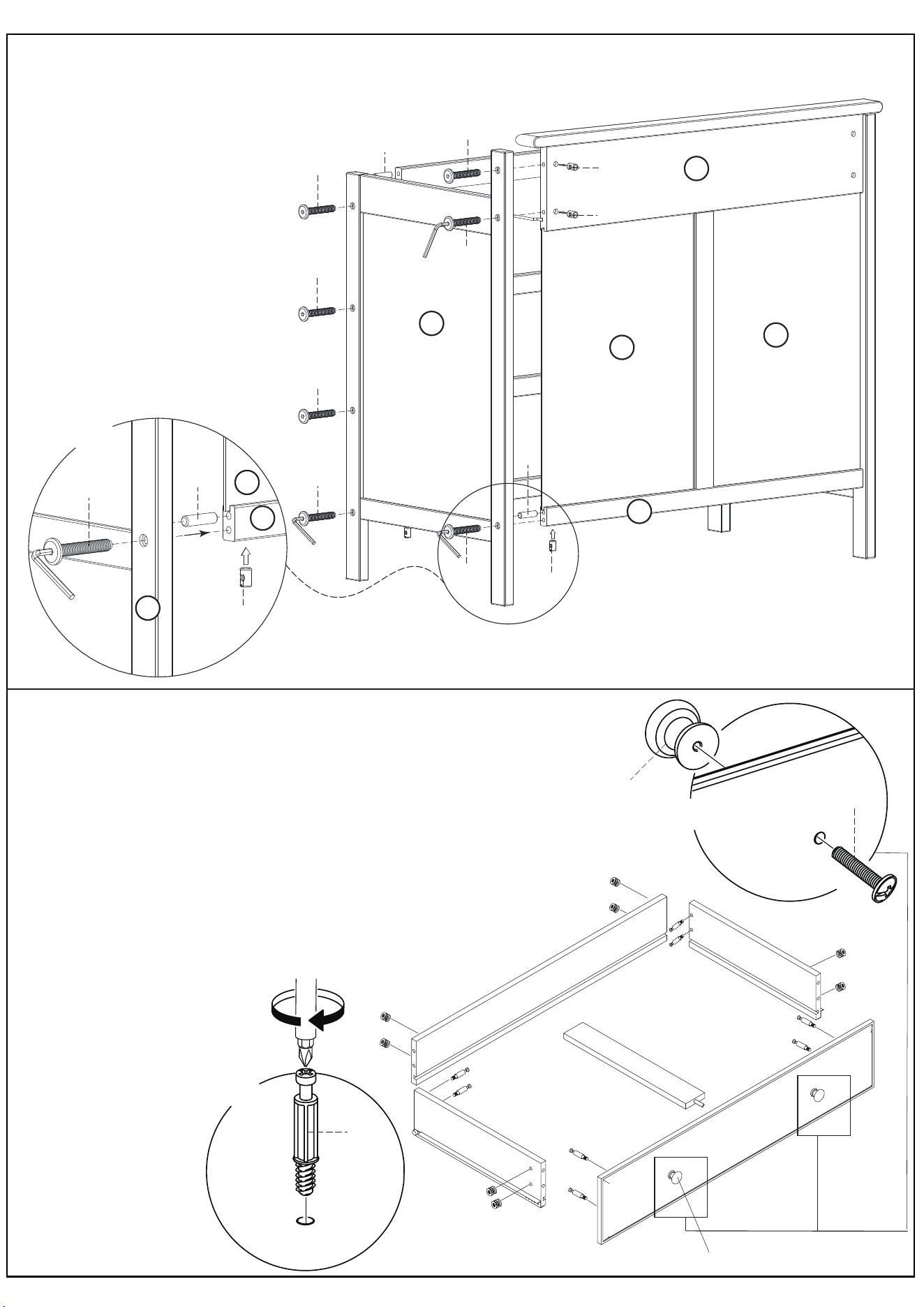
1: Thread cam bolts (f) into the pre-drilled holes on the front panel (DR1),
side panel (DR2), back panel (DR3).
2: Insert cams (g) into the holes on side panel (DR2), back panel (DR3).
3: Attach the knob (e) to the front panel (DR1) using screws(d) .
STEP 5
e
DR1
DR1
DR2.2
DR5
DR2.1
f
f
f
g
g
g
DR3
d
d
d
d
a
a
a
a
a
a
a
a
e
k
b
b
b
STEP 4
Attach the Right Side (B) to the assembly from step 3 with Bolts (a) and Barrel nut (d) with wood dowel (b) using the
M4 Allen Wrench as shown.
ÉTAPE 5
ÉTAPE 4
1 : Enfilez les pênes battants (f) dans les trouspré-percés sur le
panneau - neau latéral (DR2)
2 : Insérez les cames (g) dans les trous du panneau latéral (DR2)
et du panneau arrière (DR3).
3 : Attachez le bouton (e) au
panneau avant (DR1) en
utilisant les vis (d). avant
(DR1), le pan et le
panneau arrière (DR3).
H
H
C
B
F
X 5
B
F
H
2x
8x
7
1: Attach the bottom support panel (DR5)
to the back panel (DR3) by self-tapping (h),
to front panel (DR1) by dowel.
2: Attach the front panel (DR1) to side panel (DR2).
3: LOCK the cams (g) in the side panel
(DR2) by turning them.
4: Assemble the rest of the drawers by
repeating steps 5,6,7.
1 : Attachez le panneau de support
inférieur ( D R5) au
panneau arrière (DR3), avec l'aide
de la vis autotaraudeuse (h),
et au pannea u avant,
en utilisant un goujon.
2 : Attachez le panneau avant (DR1)
au panneau latéral (DR2).
3 : SERREZ les cames (g) dans le
panneau latéral (DR2) en les tournant.
4 : Assemblez le reste des tiroirs en
répétant les étapes 5, 6, 7.
arrière (DR3), avec l'aide et au panne
STEP 7
f
g
DR1
DR2.2
DR5
DR2.1
DR3
DR4
h
STEP 6
1: Attach side panel (DR2) to the back panel (DR3) by inserting the cam bolts (f) to the end holes of back panel (DR3).
MAKE SURE the grooves line up and face inside. LOCK the cams (g) in the back panel (DR3) by turning them.
2: Slide the bottom panel (DR4) painted side up,into grooves of side panel (DR2).
DR3
f
g
DR2.1
DR4
DR2.2
ÉTAPE 7
4 x
4 x
8
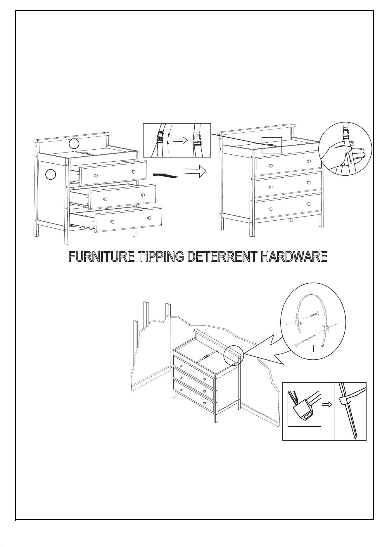
FURNITURE TIPPING DETERRENT HARDWARE
Tipping furniture may injury
young children . Use of this
tipping restraint hardware
is highly
recommended .
This hardware , when
peoperly installed , could
provide protection against
the unexpected
tipping of
HOW TO LOCKED
i
STEP 8
1: Slide the drawers into rails on head board (A&B).
NOTE :PLEASE PUT THE DRAWER WITH CLEAN STICKER AS THE TOP ONE.
2:Add the pad (L).
3.Put the child on the pad,then insert safty restraint system of the tape across child's waist. The tightness can be adjusted
by increasing the tension of the tape.
ÉTAPE 8
1 : Faites glisser les tiroirs dans les rails des têtes de lit (A et B).
N. B. : VEUILLEZ METTRE LE TIR OIR AVEC L'ÉTIQUETTE D' AVE RTISSEMEN T EN HAUT.
2 : Placez le matelas (L).
3 : Mettez l'enfant sur le matelas; serrez ensuite la sangle de sécurité autour de la taille de l'enfant. La pression peut être
ajustée en réglant la tension de la sangle.
DISPOSITIF ANTIBASCULEMENT
Les jeunes enfants peuvent être blessés par des meubles qui basculent. Il est vivement
recommandé d'utiliser ce dispositif antibasculement.
Correctement installé, ce dispositif offrira une protection contre le basculement inattendu du
meuble provoqué par l'utilisation inadéquate.
furniture due to improper use .
A
C
DR1
DR1
DR1
9
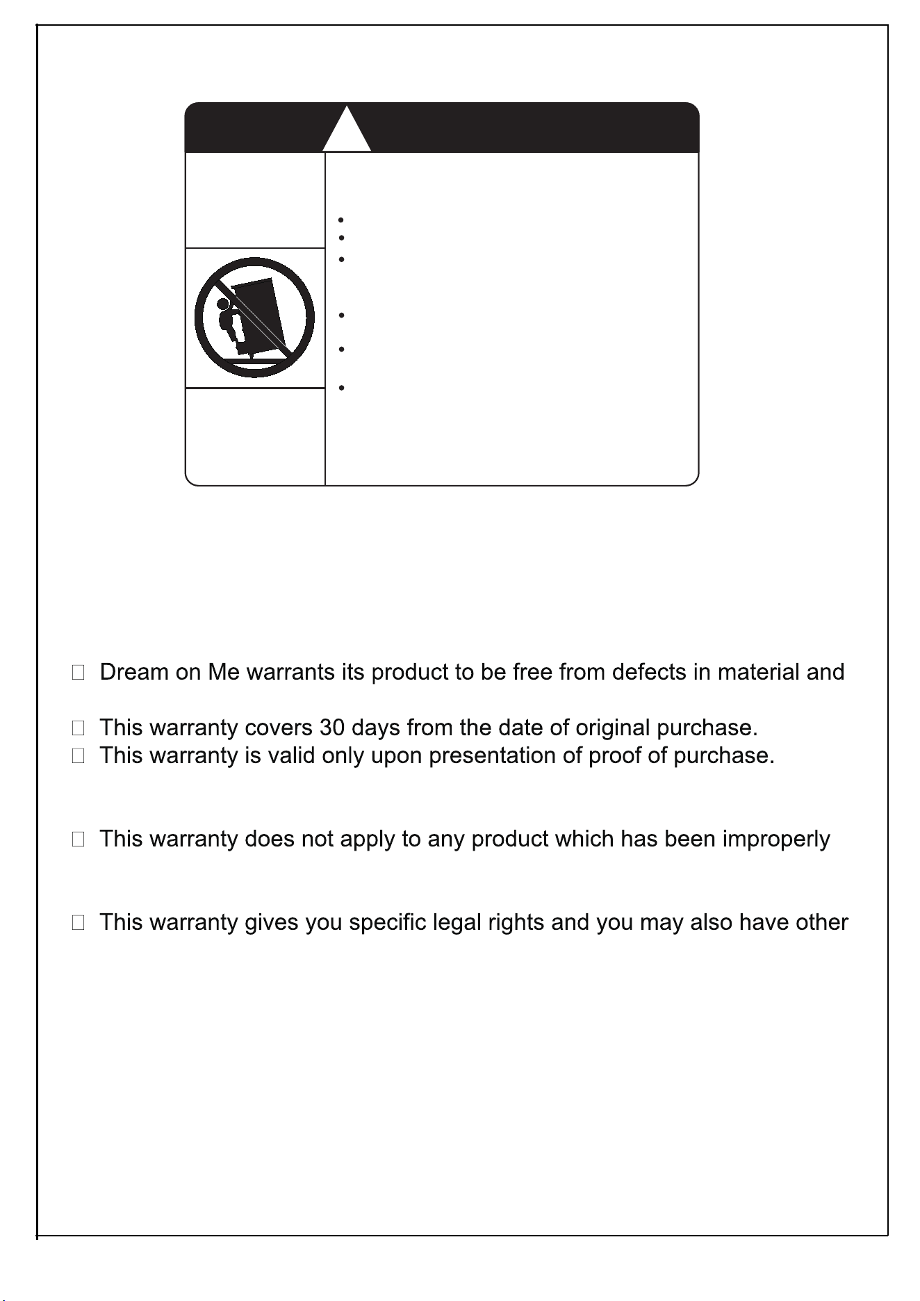
LIMITED WARRANTY
workmanship and agrees to remedy any such defect.
This is solely limited to the repair or replacement of defective furniture
components and no assembly labor is included.
assembled, subjected to misuse or abuse or which has been altered or
repaired in any way.
rights which vary from State to State.
WARNING: Should this product become damaged, and/or components
are broken or missing, DO NOT USE
Serious or fatal crushing injuries can occur
from furniture tip-over. To help prevent
tip-over:
Place heaviest items in the lower drawers.
Do not set TV’s or other heavy objects on
specifically designed to accommodate them.
the top of this product. unless the product is
Never open more than one drawer at a time.
(OR)
Never allow children to climb or hang on
drawers, doors, or shelves.
Do not defeat or remove the drawer interlock
system.
Use of tip-over restraints may only reduce,
but not eliminate, the risk of tip-over.
This is a permanent label. DO NOT remove!
Install tipover restraint provided.
WARNING
!
Enter our monthly giveaway!
Simply scan the QRcode to register.
Chat with us!
For any questions or concerns or feedback.
1532, S. Washington Avenue
Piscataway, NJ 08854
E-mail: [email protected]
www.dreamonme.com
Follow us on
to get your nursery featured on our social media.
@dreamonmeinc
@dreamonmeinc