81021
ASSEMBLY AND USER’S GUIDE
SKU: 81021
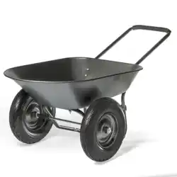
DUAL WHEEL WHEELBARROW
METAL TRAY 16 INCH FLAT-FREE TIRE
Read all safety warnings and instructions. Failure to follow
the warnings and instructions may result in serious injury.
Save all warnings and instructions for future reference.
DANGER

THIS PAGE INTENTIONALLY LEFT BLANK

1
TABLE OF CONTENT
CUSTOMER SERVICE
If you have any questions about ordering our pool pumps and replacement parts or pool products,
please feel free to contact us using the following contact information:
Customer Service and Technical Support
Phone: (909) 628-0880
Email: [email protected]
Hours of Operation: Monday – Friday, 9AM – 4PM (CST)
IMPORTANT SAFETY INSTRUCTIONS .........................................................
Legends and Symbols ...............................................................................................
GENERAL SAFETY INFORMATION ...............................................................................
PRODUCT INFORMATION .............................................................................
OVERVIEW ......................................................................................................................
INTRODUCTION ..............................................................................................................
SPECIFICATION ..............................................................................................................
ASSEMBLY INSTRUCTIONS ..........................................................................
STEP 1 ..............................................................................................................................
STEP 2 .............................................................................................................................
STEP 3 .............................................................................................................................
STEP 4 .............................................................................................................................
STEP 5 .............................................................................................................................
STEP 6 .............................................................................................................................
STEP 7 .............................................................................................................................
REPLACEMENT PARTS .................................................................................
PARTS DIAGRAM ............................................................................................................
PARTS LIST .....................................................................................................................
DISCLAIMER ...................................................................................................
Disclaimer ..................................................................................................................
Customer Service ......................................................................................................
1
2
3
4
4
5
6
7
7
8
9
10
11
12
13
14
14
14
15
15
15
2
IMPORTANT SAFETY INSTRUCTIONS
For safety reasons, children should not be allowed to use this product.
Packing materials and plastic bags are not toys. Keep them away from children to prevent the risk
of suffocation.
Failure to comply with all instructions and warnings may lead to severe bodily
injury or even death. For optimal safety and functionality, it is advisable to have the product installed
and serviced by a certified service professional. Prior to using this product, installers, operators, and
owners must carefully review these warnings and all instructions provided in the owner's manual. It
is essential to leave these warnings and the owner's manual with the owner for their reference and
safety.
ATTENTION INSTALLER: This manual contains vital information regarding the installation,
operation, and safe use of this product. It is essential to provide this manual to the end user of the
product. Failure to read and follow all instructions could lead to severe injuries.
USE OF NON-XTREMEPOWERUS REPLACEMENT PARTS VOIDS WARRANTY
DANGER: Ignoring these hazards can result in death, severe personal injury, or
significant property damage.
WARNING: Indicates potential hazards that can result in severe personal injury,
death, or significant property damage. Ignoring these warnings presents a real
danger.
CAUTION: Indicates potential hazards that can result in minor or moderate
personal injury, property damage, or actions that are unpredictable and unsafe.
Ignoring these cautions presents a potential hazard.
NOTICE: This label indicates important special instructions that are not directly
related to hazards.
This guide provides instructions for installing and using the Pallet Truck Stacker Dolly Lift. If you
have any questions about the equipment, please contact XtremepowerUS.
This guide contains important information about safely installing and operating this product. After
installation, make sure to share this information with the owner/operator or leave it with them for
their reference.
Legends and Symbols
When you come across the safety-alert symbol on your equipment or in this manual, pay attention
to the following signal words and remain vigilant about the potential for personal injury.
IMPORTANT SAFETY INSTRUCTIONS
DANGER
WARNING
WARNING
CAUTION
NOTE
DANGER
3
IMPORTANT SAFETY INSTRUCTIONS
DANGER
WARNING
CAUTION
NOTE
GENERAL SAFETY INFORMATION
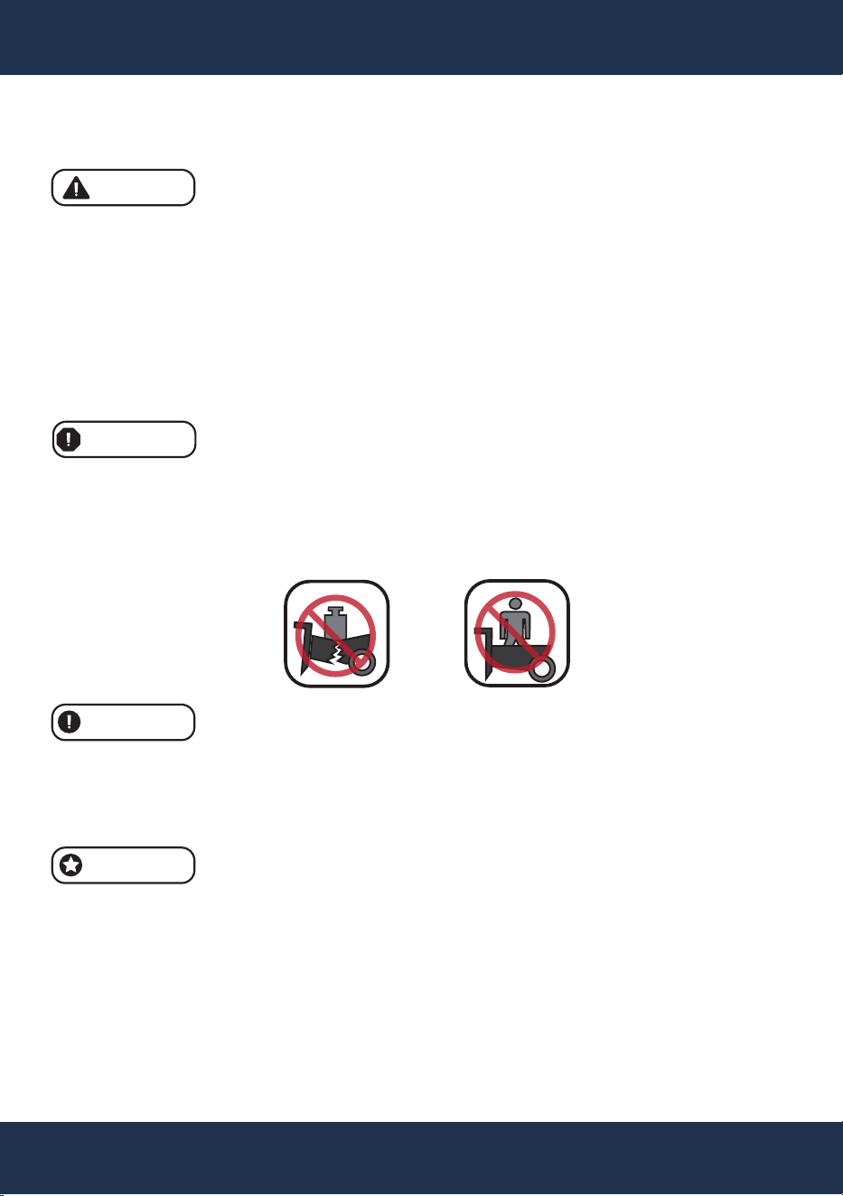
• Weight Limit: Do not exceed the weight limit of 330 lbs. Overloading may result in injury or
damage.
• Avoid Riding: Do not sit or ride in the wheelbarrow.
• Proper Use: Follow the manufacturer’s instructions for proper use.
• Usage Restrictions: This item is not to be used as a step ladder or for any purpose other
than its intended function.
• Exceeding Load Capacity: Never exceed the recommended load capacity, as overloading
may cause the wheelbarrow to tip, posing serious risks.
• Emergency Lowering: In the event of an emergency, lower the load immediately if it is safe
to do so.
• Loading Guidelines: Always distribute the load evenly across the surface of the tray.
• Stable Loading: Do not place weight on the edges of the tray, as this can cause imbalance
or damage.
• Sharp Edges: Be cautious when handling parts that may have heavy or sharp edges.
• Assembly and Maintenance: Firmly secure all bolts, screws, and knobs before use.
• Pre-Use Inspection: Reconfirm that all bolts, screws, and knobs are secure every 90 days.
• Keep these instruction for future use.
• Child Safety: Do not allow children to use this item unsupervised.
• Avoid Hazards: Avoid using the wheelbarrow near sharp or hazardous objects to prevent
tire damage.
• Condition of Equipment: Cease use if any parts are missing, broken, or worn. Ensure all
repairs and replacements are made before reuse.
4
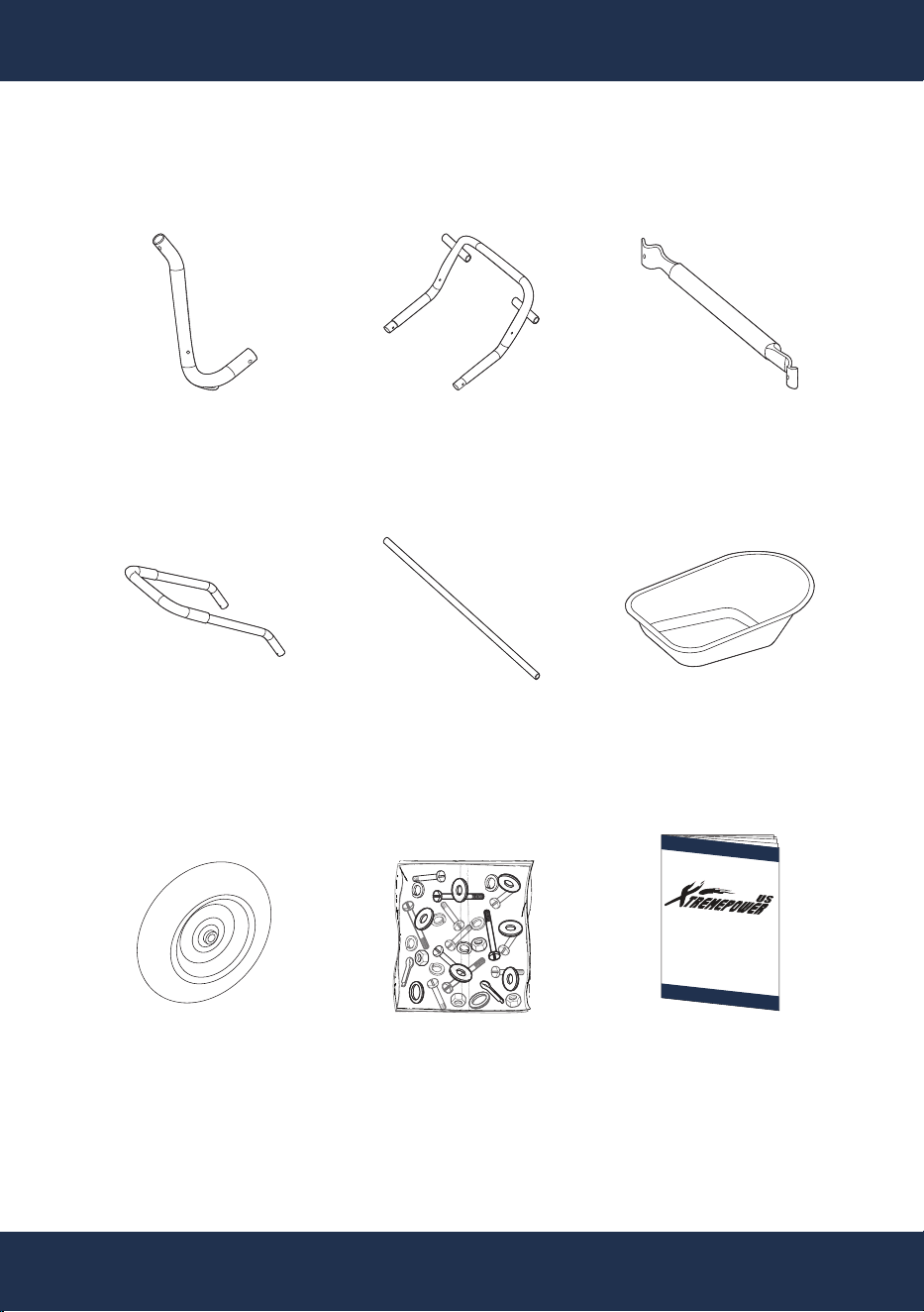
OVERVIEW (PRODUCT INFORMATION)
PART#: A
BACK FRAME
2 PC(S)
PART#: B
FRONT FRAME
1 PC(S)
PART#: C
CENTER SUPPORT
1 PC(S)
PART#:
D
HANDLE
1 PC(S)
PART#: E
AXLE
1 PC(S)
PART#: F
TRAY
1 PC(S)
PART#:
G
WHEEL
2 PC(S)
PACKAGE CONTENTS
PARTS
PART#: H
HARDWARE BAG
1 PC(S)
INSTRUCTION
MANUAL
1 PC(S)
5
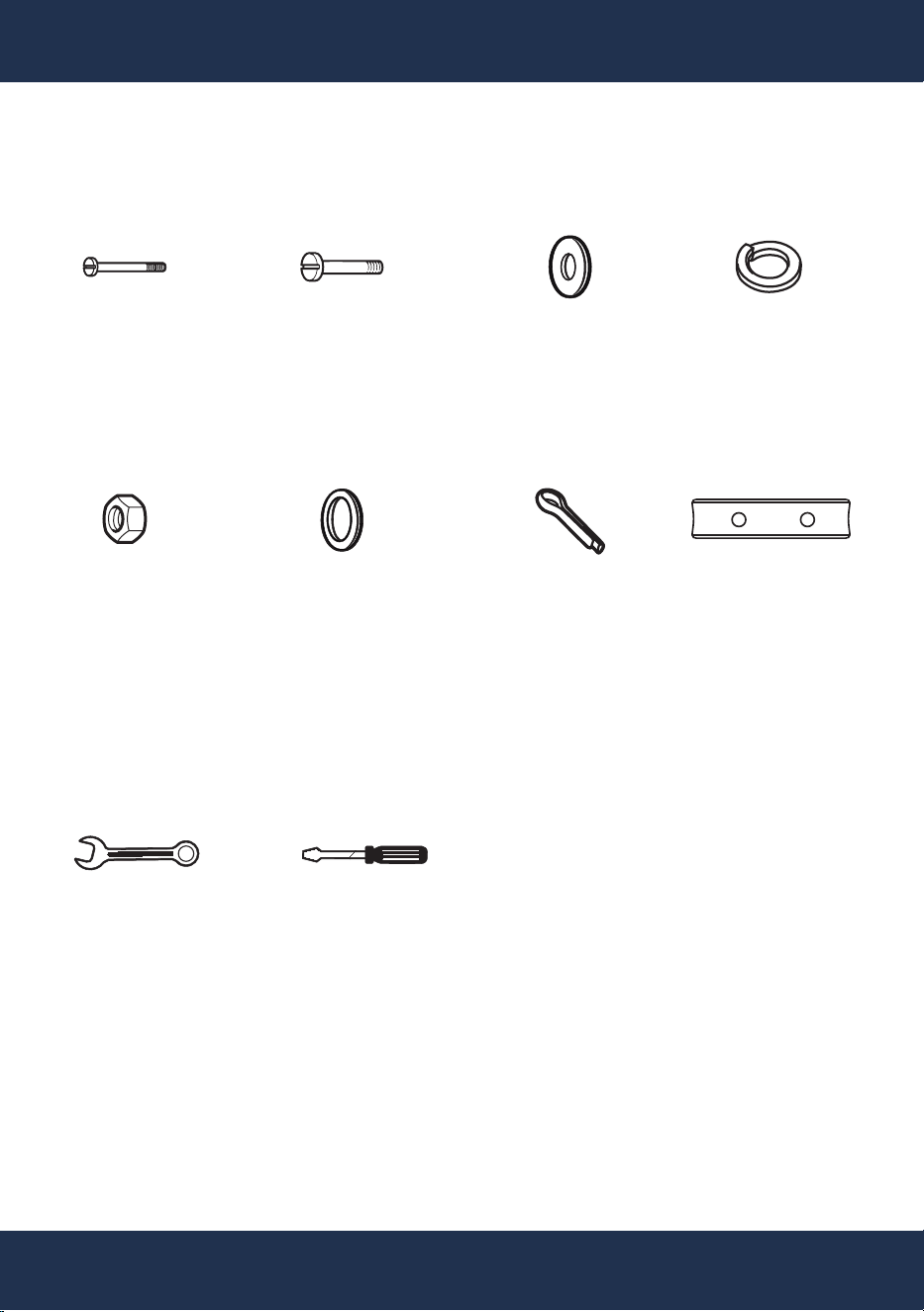
OVERVIEW (PRODUCT INFORMATION)
PART#: 8
PLASTIC SPACER
2 PC(S)
PART#:
1
BOLT
6 PC(S)
PART#: 2
BOLT
4 PC(S)
PART#: 3
WASHER
10 PC(S)
PART#: 4
SPRING WASHER
10PC(S)
8 x 45MM 8 x 40MM 8MM 8MM
PART#: 6
WASHER (FOR WHEEL)
2 PC(S)
PART#: 7
COTTER PIN
2 PC(S)
PART#:
5
NUT
10 PC(S)
8MM
TOOLS REQUIRED
SMALL
WRENCH
FLATHEAD
SCREWDRIVER
15MM
PACKAGE CONTENTS
HARDWARE BAG - PART# H
6
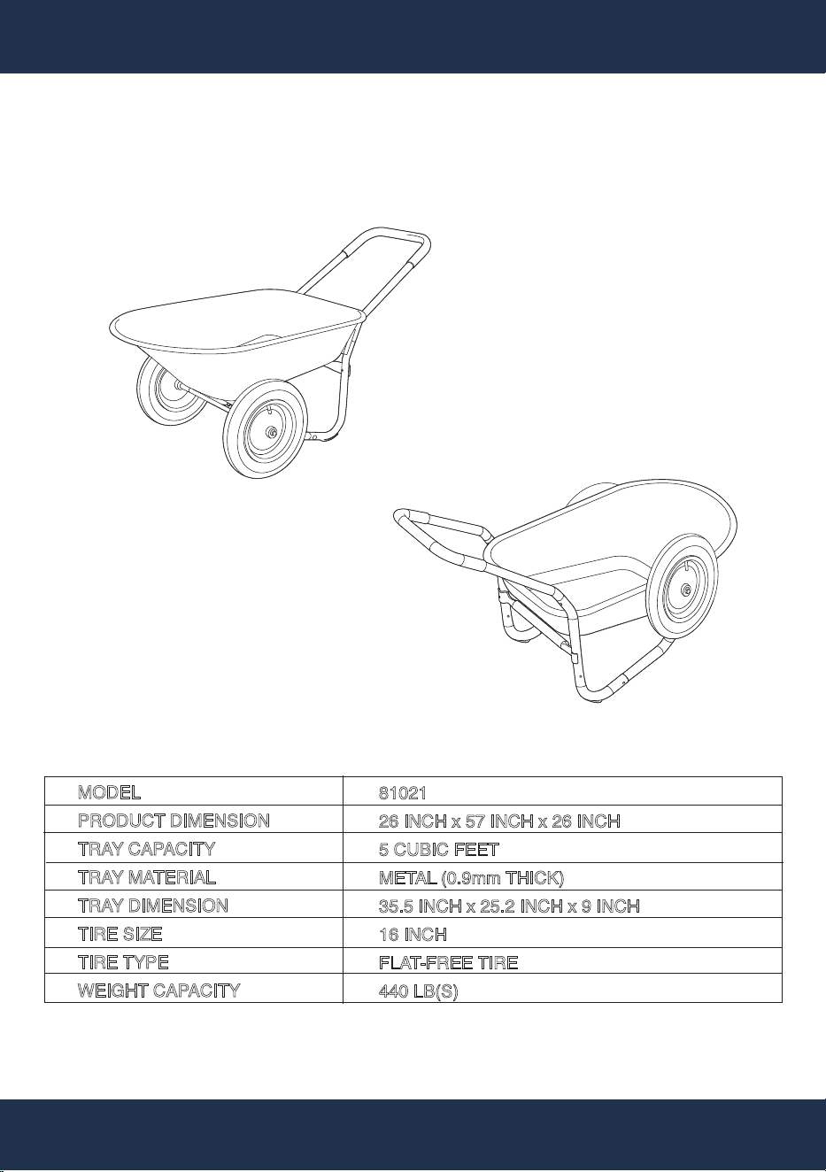
OVERVIEW (PRODUCT INFORMATION)
OVERVIEW (PRODUCT INFORMATION)
FRONT VIEW
REAR VIEW
SPECIFICATIONS
MODEL
PRODUCT DIMENSION
TRAY CAPACITY
TRAY MATERIAL
TRAY DIMENSION
TIRE SIZE
TIRE TYPE
WEIGHT CAPACITY
81021
26 INCH x 57 INCH x 26 INCH
5 CUBIC FEET
METAL (0.9mm THICK)
35.5 INCH x 25.2 INCH x 9 INCH
16 INCH
FLAT-FREE TIRE
440 LB(S)
HANDLE
7
ASSEMBLY
PART#: A
PART#: 2
PART#: 5
PART#: 4
PART#: 3
PART#: 3
PART#: 4
PART#: 5
x2 x1 x2 x2 x2 x2
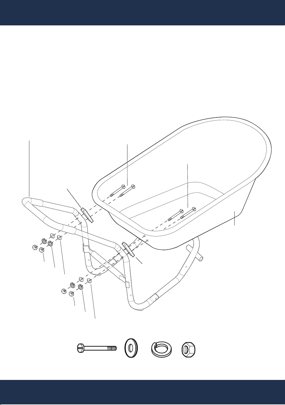
ASSEMBLY INSTRUCTION
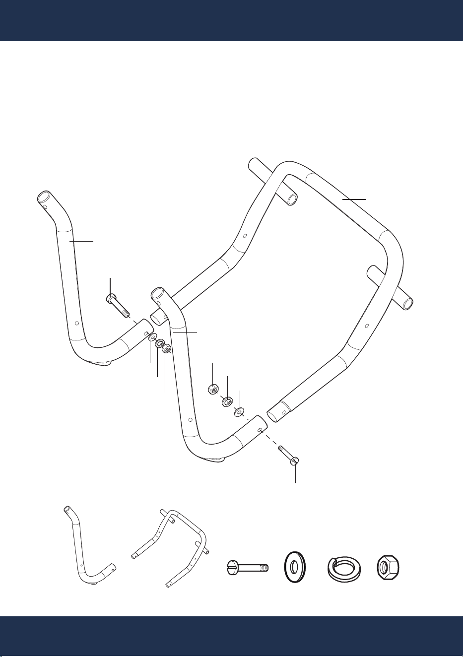
STEP 1
PART#: B
PART#: 2
Attach PART# A to PART# B.
Secure with PART# 2 , PART# 3, PART# 4 , and PART# 5 .
PART#:
A
8
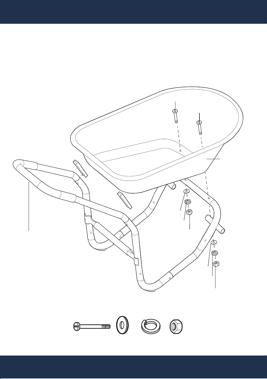
ASSEMBLY
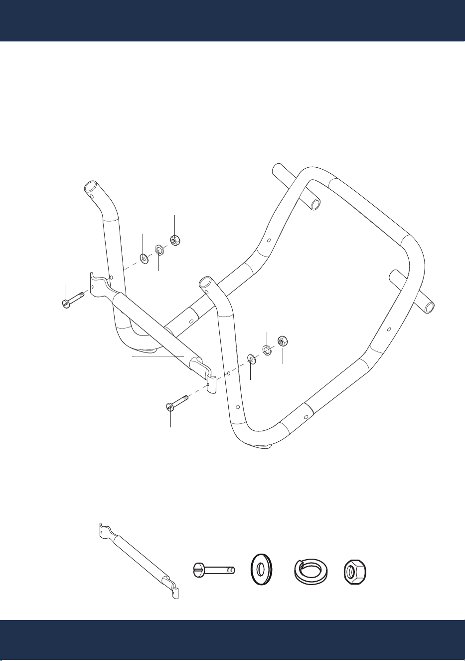
STEP 2
PART#: C
PART#: 2
PART#: 5
PART#: 4
PART#: 3
PART#: 5
PART#: 3
PART#: 4
PART#: 2
Attach PART# C.
Secure with PART# 2 , PART# 3, PART# 4 , and PART# 5 .
1x 2x 2x 2x 2x
9
ASSEMBLY
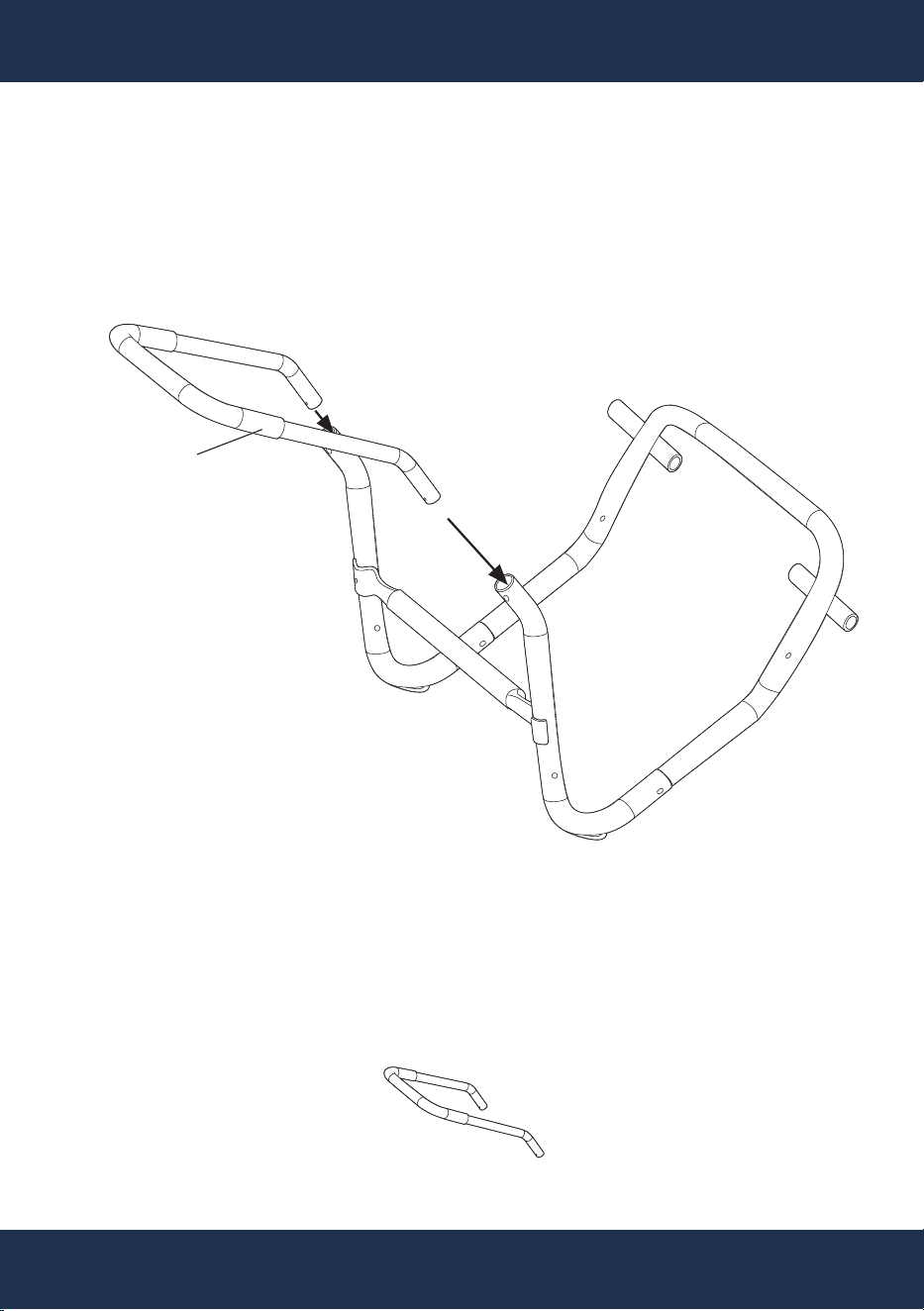
Insert PART# D.
STEP 3
PART#: D
x1
10
ASSEMBLY
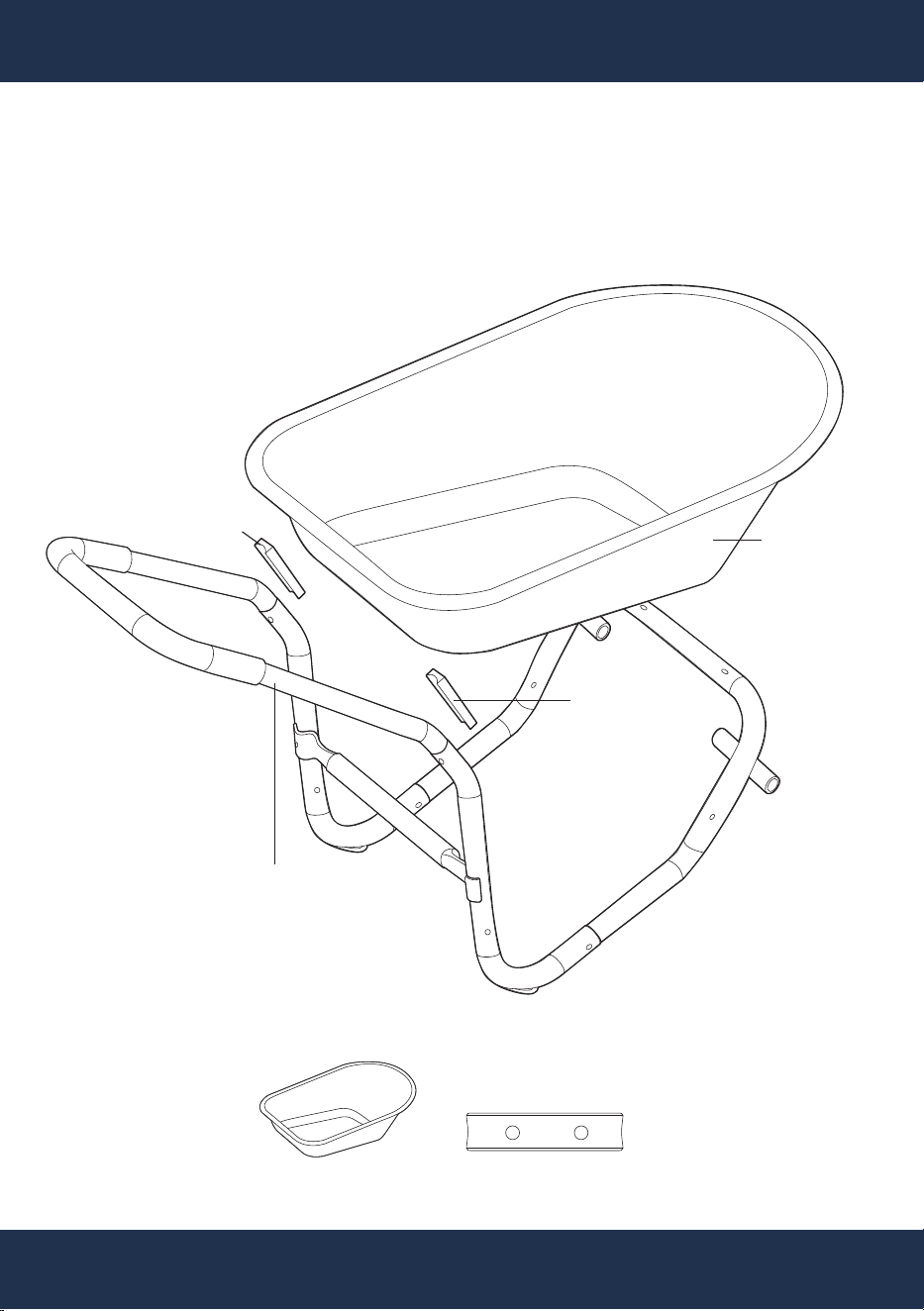
x1 x2
Attach PART# F to HANDLE FRAME, and place PART# 8 between PART# F and
HANDLE FRAME.
STEP 4
PART#: 8
PART#: 8
PART#: F
HANDLE FRAME
11
ASSEMBLY
PART#: 3
Secure PART# F, PART# 8, and HANDLE FRAME with PART# 1, PART# 3,
PART# 4, and PART# 5.
STEP 5
PART#: F
PART#: 8
PART#: 8
PART#: 5
PART#: 4
PART#: 1
HANDLE FRAME
x4 x4 x4 x4
PART#: 3
PART#: 5
PART#: 4
PART#: 1
12
ASSEMBLY
Secure PART# F and HANDLE FRAME with PART# 1, PART# 3, PART# 4, and
PART# 5.
STEP 6
PART#: F
PART#: 1
PART#: 1
PART#: 3
PART#: 4
PART#: 5
PART#: 3
PART#: 4
PART#: 5
HANDLE FRAME
2x 2x 2x 2x
13
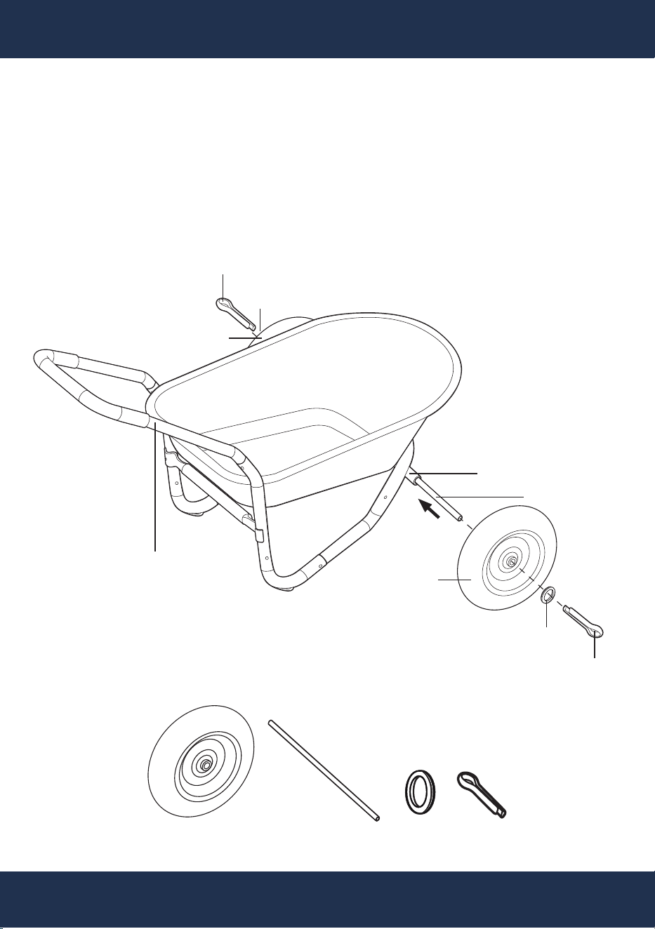
ASSEMBLY
ASSEMBLY
Slide PART# E through the AXLE SOCKET on HANDLE FRAME.
Attach PART# G to PART# E, secure with PART# 6 and PART# 7, and bend the
pin of PART# 7 to firmly lock PART# H in place.
Repeat the same process on the other end of PART# E.
STEP 7
PART#: E
AXLE SOCKET
PART#:
G
PART#: 6
PART#: 7
PART#: 7
HANDLE FRAME
PART#: G
PART#: 6
x2 x2 x2 x2

IMPORTANT SAFETY INSTRUCTIONS
14
PART#: D
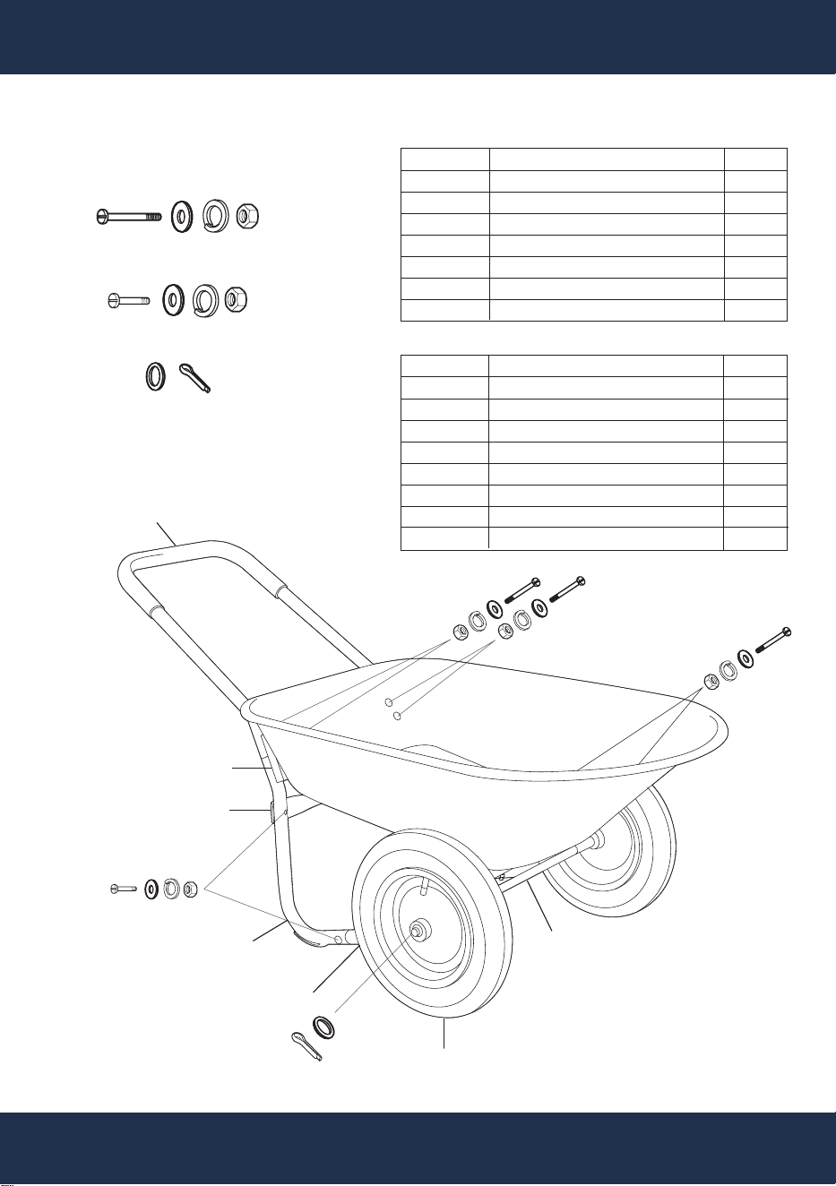
REPLACEMENT PARTS
REPLACEMENT PARTS
PARTS DIAGRAM
PART#: B
PART#: A
PART#: G
PART#: 8
PART#: F
PART#: C
PART#: E
PART#
A
B
C
D
E
F
G
DESCRIPTION
BACK FRAME
FRONT FRAME
CENTER SUPPORT
HANDLE
AXLE
TRAY
WHEEL
QTY
2
1
1
1
1
1
2
PART#: 1, 3, 4, 5
PART#: 1, 3, 4, 5
PART#: 6, 7
PART#: 1, 3, 4, 5
PART#: 2, 3, 4, 5
PART#: 2, 3, 4, 5
PART#: 6, 7
PART#
1
2
3
4
5
6
7
8
DESCRIPTION
BOLT 8 x 65 mm
BOLT 8 x 45 mm
WASHER 8 mm
SPRING WASHER 8 mm
NUT 8 mm
AXLE WASHER
COTTER PIN
PLASTIC SPACER
QTY
6
4
10
10
10
2
2
2
PART# H
PART# A - G
- HARDWARE BAG

15
DISCLAIMER
DISCLAIMER
PLEASE READ THE FOLLOWING CAREFULLY
The manufacturer and/or distributor have provided the parts list and assembly diagram in this manual
for reference purposes only. They do not make any representation or warranty to the buyer that they
are qualified to make repairs to the product or replace any parts of the product. In fact, the
manufacturer and/or distributor expressly state that all repairs and parts replacements should be
undertaken by certified and licensed technicians, and not by the buyer.
The buyer assumes all risk and liability arising from their repairs to the original product or replacement
parts or arising from their installation of replacement parts. It is strongly advised that qualified
professionals handle any repairs or replacements to ensure safety and proper functioning of the
product. Improper installation and operation may result in injury, property damage, or voiding of
warranty. The manufacturer and/or distributor shall not be held responsible for any accidents,
damages, or malfunctions resulting from the buyer's installation and operation of the product. It is
essential to follow all safety guidelines and recommendations provided in this manual and to seek
professional assistance if unsure about the installation or operation procedures.
CUSTOMER SERVICE
If you have any questions about ordering our pool pumps and replacement parts or pool products,
please feel free to contact us using the following contact information:
Customer Service and Technical Support
Phone: (909) 628-0880
Email: [email protected]
Hours of Operation: Monday – Friday, 9AM – 4PM (CST)