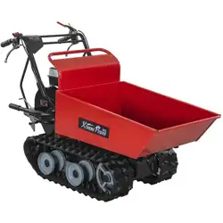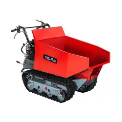

MINI TRACKED DUMPER
2
GB
TABLE OF CONTENTS
Specifications
INTRODUCTION
Introduction 2
Specifications 2
Symbols 3
Safety 4
General Safety Rules 4
Specific Safety Rules 6
Unpacking the Container 7
Contents Supplied 8
Know your Machine 9
Features & Controls 9
Operation 11
Maintenance 13
Transporting 18
Storage 18
Hydraulic Scheme 18
Trouble Shooting 19
Parts Schedule 20
Parts List 22
Your new mini tracked dumper will more
than satisfy your expectations. It has been
manufactured under stringent quality
standards to meet superior performance
criteria. You will find it easy and safe to
operate, and with proper care, it will give you
many years of dependable service.
Carefully read through this entire
operator’s manual before using this
unit. Take special care to heed the
cautions and warnings.
The four-speed gearbox, three forward and
one reverse, lies at the heart of the unit. It is
oversized so as to manage safely the huge
torques generated by the engine. Thanks to
its efficient reduction gearing, it is capable of
moving around in every situation and bearing
any load.
The Engine manufacturer is responsible
for all engine-related issues with regards to
performance, power rating, specifications,
warranty and service. Please refer to the
Engine Manufacturer’s owner’s/operator’s
manual, packed separately with your unit, for
more information.
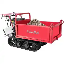
Item No. 09737 09737A
Engine 4800W 6615W
Transmission 6 Forward / 2 Reverse
Load Capacity 500 kg
Box Length 950 mm
Box Width 680 mm
Box Depth 465 mm
Track Width 180 mm
Pump Flow 9 L/min
Sound power level 101 dB(A) k=3 dB(A)
Sound pressure level 88 dB(A) k=3 dB(A)
Vibrating level on
handlebar grips
Left 10.1 m/s2 k=1.5 m/s2
Right
11.3 m/s2 k=1.5 m/s2
Weight 263.0 kg 271.0 kg
09737UK00M100_更新回收处理标志.indd 2 2019/9/4 11:01:22
MINI TRACKED DUMPER
26
GB
09737A Gearbox (50)
09737UK00M100_更新回收处理标志.indd 26 2019/9/4 11:02:03
MINI TRACKED DUMPER
3
GB
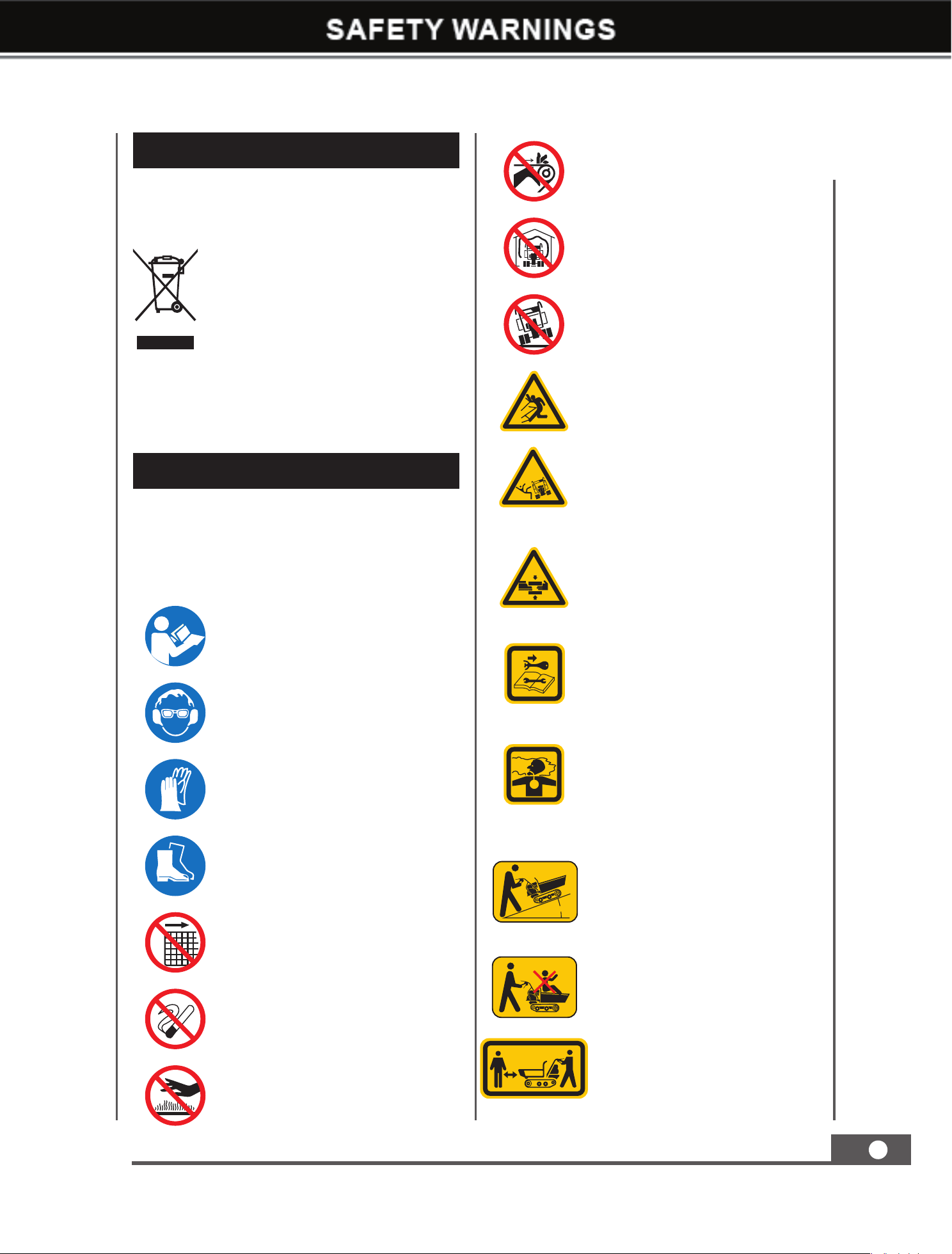
SYMBOLS
The rating plate on your machine may
show symbols. These represent important
information about the product or instructions
on its use.
Read these instructions carefully.
Wear eye protection.
Wear hearing protection.
Wear protective gloves.
Wear safety footwear.
Do not remove or tamper
with the protection and safety
devices.
No smoking, sparks, or flames
Do not touch parts that are hot
from operation. Serious burns
may result.
Keep your hands clear from all
rotating parts.
Never start or run the engine
inside a closed area.
Do not operate on slopes with
angle over 20° or tip loading at
an inclined position.
Be aware, objects may be
thrown while in use.
20° MAX
Tipping hazard!
20° MAX
Keep your feet and hands away
from moving parts. Moving
parts can crush or cut.
20° MAX
Always turn off the engine
before starting maintenance.
The exhaust fumes are dangerous,
containing carbon monoxide.
Staying in the environment can
lead to unconsciousness and
death.
20° MAX
The maximum longitudinal
climbing angle should not exceed
20 degrees.
20° MAX
Do not allow anyone sitting or
standing in the hopper while
driving.
Keep children and bystanders
off and away.
RECYCLING AND DISPOSAL
This marking indicates that this
product should not be disposed with
other household wastes. To prevent
possible harm to the environment
or human health from uncontrolled
waste disposal, recycle it responsibly
to promote the sustainable reuse of
material resources. To return your
used device, please use the return and
collection systems or check with your
local authority or local stores for advice
of environmental safe recycling.
09737UK00M100_更新回收处理标志.indd 3 2019/9/4 11:01:23
MINI TRACKED DUMPER
26
GB
09737A Gearbox (50)
09737UK00M100_更新回收处理标志.indd 26 2019/9/4 11:02:03

MINI TRACKED DUMPER
4
GB
Understand Your Machine
Read this manual and labels affixed to the
machine to understand its limitations and
potential hazards.
Be thoroughly familiar with the controls and
their proper operation. Know how to stop the
machine and disengage the controls quickly.
Make sure to read and understand all the
instructions and safety precautions as outlined
in the Engine Manufacturer’s manual packed
separately with your unit. Do not attempt to
operate the machine until you fully understand
how to properly operate and maintain the
engine and konw how to avoid accidental
injuries and/or property damage.
If the unit is to be used by someone other than
original purchaser, or is to be loaned, rented,
or sold, always provide this manual and any
needed safety training before operation.
The user can prevent and is responsible
for accidents or injuries that may occur to
themselves, to other people, or to property.
Do not force the machine beyond its limits.
Use the correct machine for your application.
Personal Safety
Do not permit children to operate this machine
at any time.
Keep children, pets, and other people not
using the unit away from the work area. Be
alert and shut off the unit if anyone enters
work area. Keep children under the watchful
care of a responsible adult.
Do not operate the machine while under the
influence of drugs, alcohol, or any medication
that could affect your ability to use it properly.
Dress properly: Wear long, heavy pants, work
boots, and work gloves. Do not wear loose
clothing, short pants, or jewelry of any kind.
Secure long hair so it is above shoulder level.
Keep your hair, clothing, and gloves away
from moving parts. Loose clothes, jewelry, or
long hair can be caught in moving parts.
Protect eyes, face, and head from objects that
may be thrown from the unit. Always wear
safety goggles or safety glasses with side
shields when operating.
Wear appropriate hearing protection.
Always keep hands and feet away from all
moving parts during operation. Moving parts
can cut or crush body parts.
Always keep hands and feet away from all
pinch points.
Do not touch parts that might be hot
from operation. Allow parts to cool before
attempting to maintain, adjust, or service.
Stay alert, watch what you are doing, and use
common sense when operating the machine.
Do not overreach. Do not operate the machine
while barefoot or when wearing sandals or
similar lightweight footwear. Wear protective
footwear that will protect your feet and
improve your footing on slippery surfaces.
Keep proper footing and balance at all times.
This enables better control of the machine in
unexpected situations.
Inspect Your Machine
Check your machine before starting it. Keep
guards in place and in working order. Make
sure all nuts, bolts, etc., are securely tightened.
Never operate the machine when it is in need
of repair or is in poor mechanical condition.
Replace damaged, missing, or failed parts
before using it. Check for fuel leaks. Keep the
machine in safe working condition.
Do not use the machine if the engine’s switch
does not turn off the engine when running.
Any gasoline powered machine that can’t be
controlled with the engine switch is dangerous
and must be replaced.
Regularly check to see that keys and adjusting
wrenches are removed from the machine area
before starting it. A wrench or a key that is
left attached to a rotating part of the machine
may result in personal injury.
Avoid accidental starting. Be sure the engine’s
switch is off before transporting the machine
or performing any maintenance or service
SAFETY
General Safety Rules
09737UK00M100_更新回收处理标志.indd 4 2019/9/4 11:01:23

MINI TRACKED DUMPER
5
GB
on the unit. Transporting or performing
maintenance or service on a machine with its
switch on invites accidents.
If the machine should start to vibrate
abnormally, stop the engine (motor) and
check immediately for the cause. Vibration is
generally a warning sign of trouble.
Engine Safety
This machine is equipped with an internal
combustion engine. Do not use on, or near,
forest-covered or brush-covered land unless
the exhaust system is equipped with a spark
arrester meeting applicable local, state, or
federal laws.
In the state of California, a spark arrester is
required by law. Other states have similar laws.
A spark arrester, if used, must be maintained
in effective working order by the operator.
Never start or run the engine inside a closed
area. The exhaust fumes are dangerous,
containing carbon monoxide, an odorless and
deadly gas. Operate this unit only in a well-
ventilated outdoor area.
Do not tamper with the engine in an effort to
get it to run at higher speeds. The maximum
engine speed is preset by the manufacturer
and is within safety limits. See engine manual.
Keep a Class B fire extinguisher on hand
when operating this machine in dry areas as a
precautionary measure.
Fuel Safety
Fuel is highly flammable, and its vapors can
explode if ignited. Take precautions when
using to reduce the chance of serious personal
injury.
When refilling or draining the fuel tank, use
an approved fuel storage container while in
a clean, well-ventilated outdoor area. While
adding fuel or operating the unit, do not
smoke, and stay away from sparks, open
flames, or other sources of ignition near the
area of operation. Never fill the fuel tank
indoors.
To avoid sparking or arcing, keep grounded
conductive objects – such as tools – away
from exposed, live electrical parts and
connections. These events could ignite fumes
or vapors.
Always stop the engine and allow it to cool
before filling the fuel tank. Never remove
the cap of the fuel tank or add fuel while the
engine is running or when the engine is hot.
Do not operate the machine with known leaks
in the fuel system.
Loosen the fuel tank cap slowly to relieve any
pressure in the tank.
Never overfill the fuel tank. Because engine
heat can cause fuel to expand, never fill the
tank to more than 12 mm below the bottom of
the filler neck. This will provide space for fuel
expansion.
Replace all fuel tank and container caps
securely and wipe up spilled fuel. Never
operate the unit without the fuel cap securely
in place.
Avoid creating a source of ignition for spilled
fuel. If fuel is spilled, do not attempt to start
the engine. Instead, move the machine away
from the area of spillage and avoid creating
any source of ignition until fuel vapors have
dissipated.
When fuel is spilled on yourself or your
clothes, wash your skin and change clothes
immediately.
Store fuel in containers specifically designed
and approved for fuel storage.
Store fuel in a cool, well-ventilated area, safely
away from sparks, open flames, or other
sources of ignition.
Never store fuel – or a machine with fuel in
the tank – inside a building where fumes may
reach a spark, open flame, or any other source
of ignition (such as a water heater, furnace, or
clothes dryer). Allow the engine to cool before
storing in any enclosure.
09737UK00M100_更新回收处理标志.indd 5 2019/9/4 11:01:23

MINI TRACKED DUMPER
6
GB
Thoroughly inspect the area to be worked.
Keep the working area clean and free of debris
to prevent tripping. Operate on flat, level
ground.
Never place any part of your body where
it would be in danger if movement should
occur during assembly, installation, operation,
maintenance, repair, or relocation.
Keep all bystanders, children, and pets at least
23m away. If you are approached, stop the
unit immediately.
Do not mount anything on the hopper and
never carry passengers.
Never park the machine in a place with
unstable ground that could give way,
particularly when it is full.
Disengage clutch lever before starting the
engine.
Start the engine carefully according to
instructions and with feet away from the
moving parts.
Never leave the operating position when the
engine is running.
Always hold the unit with both hands when
operating. Keep a firm grip on the handlebars.
Be aware that the machine may unexpectedly
bounce upward or jump forward if the
machine should strike buried obstacles such
as large rocks or roots.
Walk, never run with the machine.
Do not overload the machine capacity. Always
drive at a safe speed, and adjust the speed to
the slope of the land, the surface conditions of
the road, and the weight of the load.
Use extreme caution when in reverse or
pulling the machine towards you.
Exercise extreme caution when operating on
or crossing gravel drives, walks, or roads. Stay
alert for hidden hazards or traffic.
On soft ground, drive at the first forward/
reverse gear. Do not rapidly accelerate, turn
sharply or stop.
Pay the utmost attention when working on
frozen ground, as the machine may tend to
skid.
Do not operate the machine in confined areas
where there may be a risk of crushing the
operator between the machine and another
object.
Never operate the machine on slopes where
angle is over 20°.
When operating on a slope, whether moving
forward or in reverse, always make certain that
the weight is evenly balanced. Always operate
the machine straight up or down slopes, never
drive sideways or across the slope. Do not
shift gears on slopes.
When dumping the contents of the hopper,
the center of gravity will change continuously
and the ground conditions will be essential for
the stability of the machine. Use extra caution
and control when dumping the hopper on
unstable ground, such as wet clay or soil.
Specific Safety Rules
09737UK00M100_更新回收处理标志.indd 6 2019/9/4 11:01:23
MINI TRACKED DUMPER
7
GB
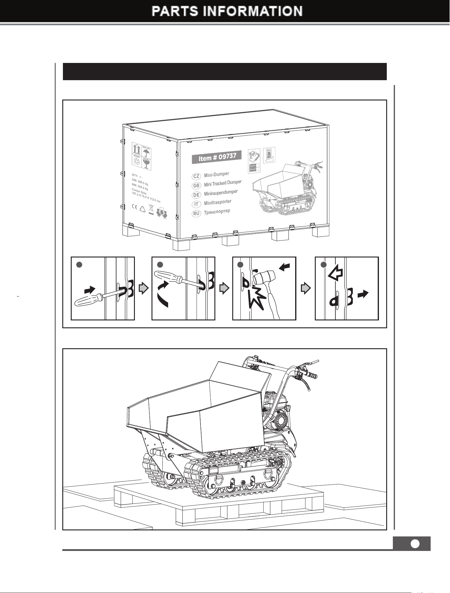
UNPACKING THE CONTAINER
Use the screwdriver and hammer to open all the side locks.
Remove all the plywood plates, and remove all the loose parts on the bottom pallets.
1 2 3 4
QTY: 1 -
GW: 298.5 kg
NW: 255.5 kg
Carton Size:
167.5 X 75.5 X 112.5 cm
Mini Tracked Dumper
Item # 09737
GB
MiniraupendumperDE
Mini-DumperCZ
MinitrasporterIT
ɌɪɚɧɫɩɨɪɬɟɪRU
5
00
9
,0 HP
6
,5 HP
09737UK00M100_更新回收处理标志.indd 7 2019/9/4 11:01:24
MINI TRACKED DUMPER
8
GB
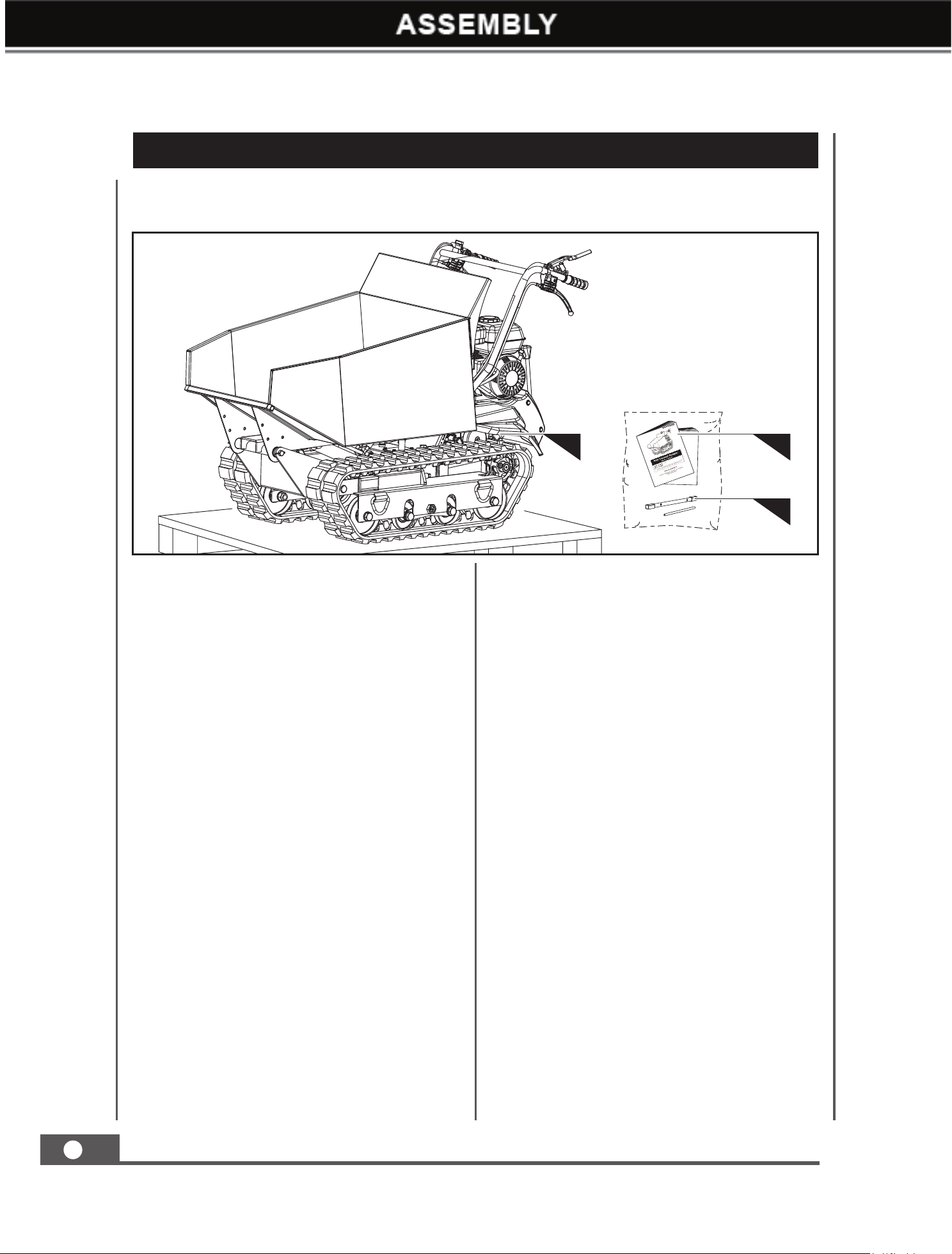
The mini tracked dumper comes partially assembled and is shipped in carefully packed package.
After all the parts have been removed from the package, you should have:
CONTENTS SUPPLIED
1. Machine
2. Operator’s Manual & Engine Manual
3. Tools for Spark Plug Assembly
3
1
2
09737UK00M100_更新回收处理标志.indd 8 2019/9/4 11:01:25
MINI TRACKED DUMPER
9
GB
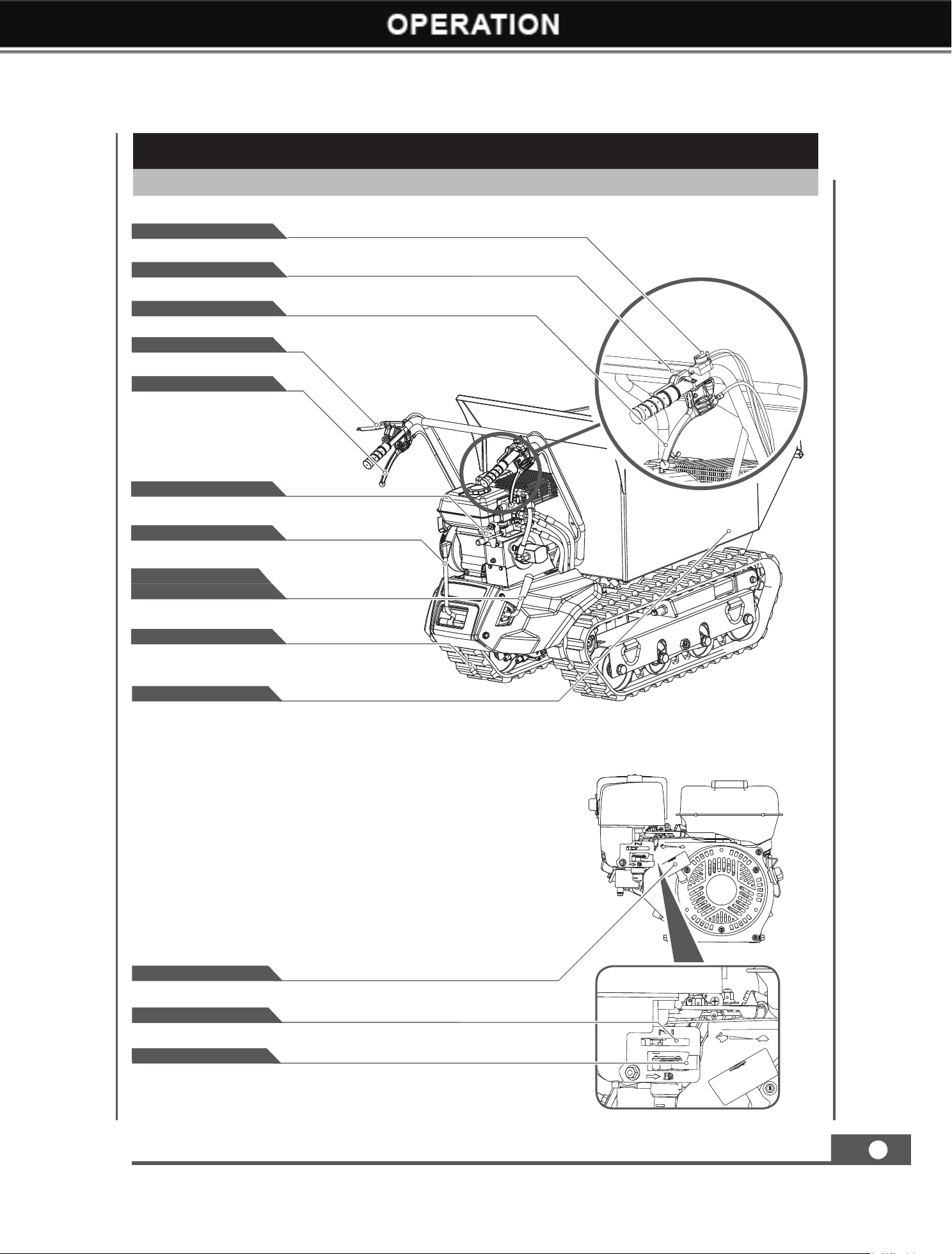
KNOW YOUR MACHINE
Features and Controls
Recoil Starter Handle
Choke Control
Fuel Shut-Off Valve
Throttle Control
Engine Switch
Right Steering Lever
Clutch Control Lever
Left Steering Lever
Hopper
Track
Gear Selection Lever
Hydraulic Tipping Handle
High/Low Speed
Shifting Handle
09737UK00M100_更新回收处理标志.indd 9 2019/9/4 11:01:28
MINI TRACKED DUMPER
10
GB
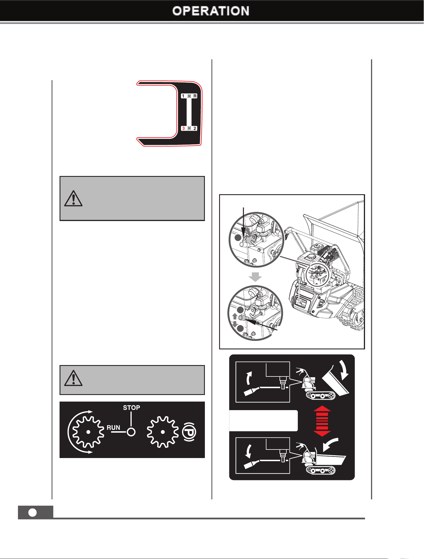
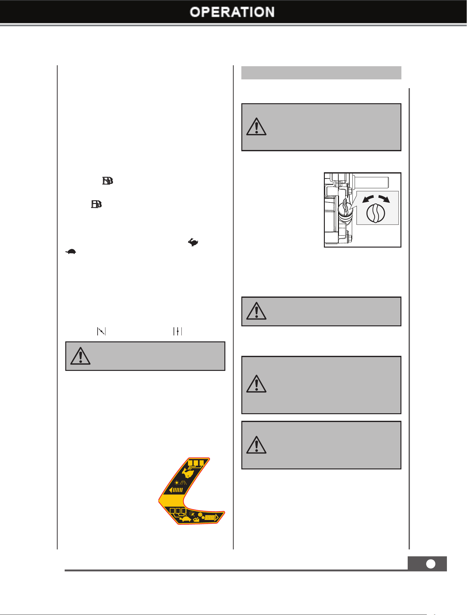
Gear Selection Lever
The gear selection
lever has 4 positions:
3 forward speeds and
1 reversefor both high
and low speed.To
change speeds, move
the speed shift lever to
the desired position.
The lever locks in a
notch at each speed
selection.
Hydraulic Tipping Handle
Using your left hand, pull the locking plate
up to release the tipping handle, and hold in
position.
Slower speeds are for heavier loads, while
faster speeds are for transporting light loads
or an empty hopper. It is recommended that
you use a slower speed until you are familiar
with the operation of the mini tracked dumper.
If the engine slows down under a load or the
tracks slip, shift the machine into a lower gear.
If the front of the machine rides up, shift
the machine into a lower gear. If the front
continues to ride up, lift up on the handles.
Always release the clutch control
lever before changing speeds.
Failure to do so will result in
damage to the mini tracked dumper.
Operate the steering levers only at
a reduced speed.
To raise the hopper, pull the tipping handle
upwards (as Ill. B in the figure) until the
hopper has reached the desired position. To
stop raising the hopper, simply release the
tipping handle and return the locking plate to
its original position.
To lower the hopper, first pull the locking plate
up with your left hand to release the tipping
handle, and then pull the tipping handle down
(as Ill. C in the figure) with the right hand.
When the hopper is lowered to the original
position, release the tipping handle back to
its original position and lock securely with the
locking plate.
Locking Plate
A
Hydraulic Tipping Handle
C
B
QUICK CHANGE
Left/Right Steering Lever
Operate the lever to turn left/right.
09737UK00M100_更新回收处理标志.indd 10 2019/9/4 11:01:30
MINI TRACKED DUMPER
11
GB
Operation
Never use choke to stop engine.
No oil in the engine originally, but
a bottle of engine oil is in scope
of delivery. Don’t start the engine
before adding oil.
Gasoline is highly flammable and
explosive. You can be burned or
seriously injured when handling fuel.
Use extreme care when handling
gasoline.
Fill the fuel tank outdoors, never
indoors. Gasoline vapors can ignite
if they collect inside an enclosure.
Explosion can result.
DO NOT OVERFILL. Check engine
oil level daily and add as needed.
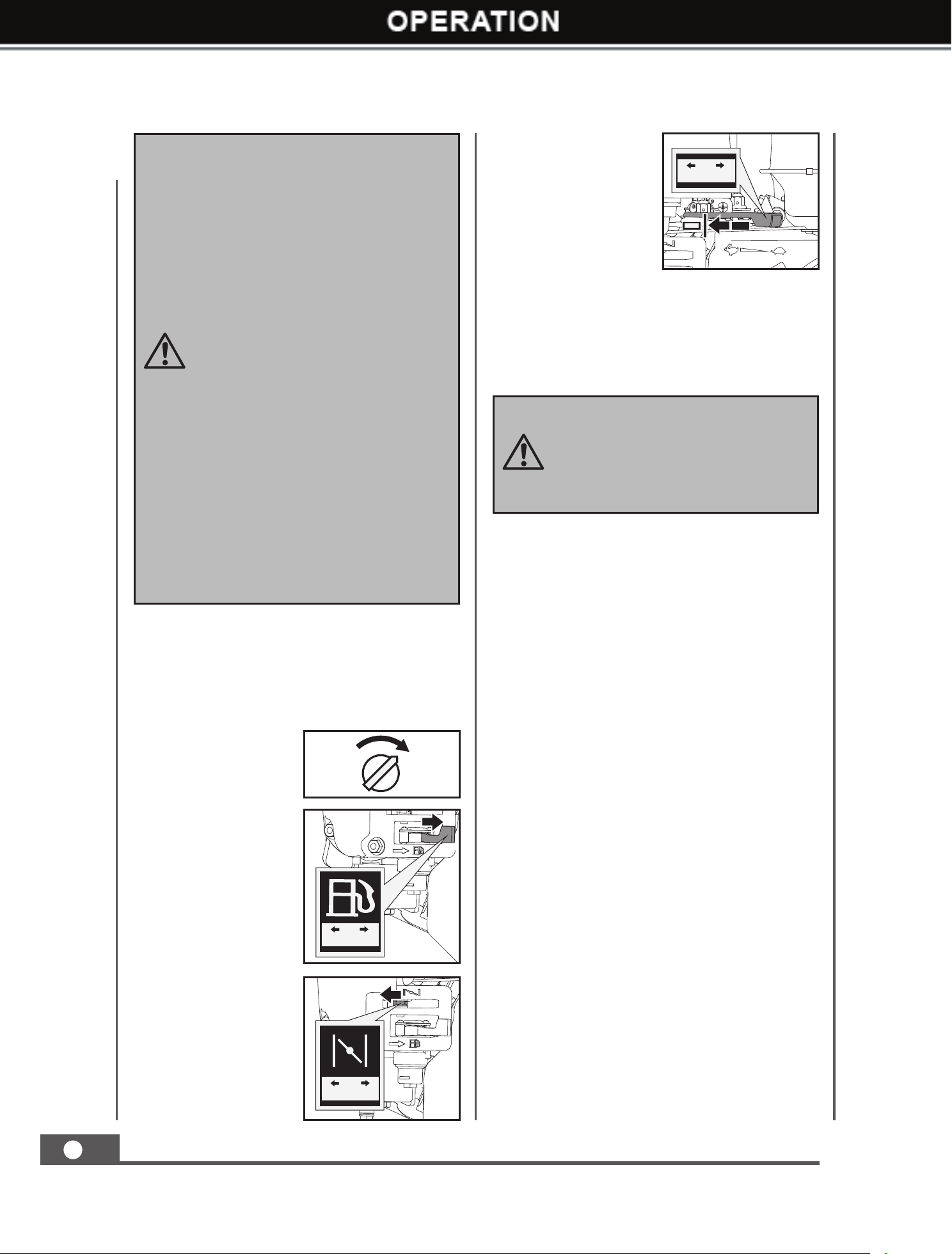
Engine On/Off Switch
The engine switch has two positions. OFF -
engine will not start or run. ON - engine will
start and run.
Recoil Starter Handle
The Recoil Starter Handle is used to start the
engine.
Fuel Shut-Off Valve
The fuel shut – off has two position.
CLOSED (
) - use this position to service,
transport, or store the unit.
OPEN (
) - use this position to run the unit.
Throttle Control
The throttle control regulates the speed of the
engine, and moves between FAST
, SLOW
, and STOP positions.
The throttle control will shut off the engine
when it is moved to the STOP position.
Choke Control
The choke control is used to choke the
carburetor and assist in starting the engine.
The choke control slides between the CHOKE
CLOSED
and CHOKE OPEN positions.
Clutch Control Lever
Squeeze the control lever, clutch engaged.
Release the lever, clutch disengaged.
High / Low Speed
Shifting Handle
High speed mode is
preferred in good driving
conditions such as good
weather and stable
ground. Otherwise, use
low speed mode.
Pull the speed shifting
handle backward to
enable high speed mode
and push it forward to
switch to low speed
mode.
1. Make sure the mini tracked dumper is on a
flat, level surface.
1. The engine must be off and allowed to cool
at least two minutes before adding fuel.
2. Remove the fuel filler cap and fill the tank.
(See engine manual for fuel capacity, fuel
recommendation, and location of fuel cap.)
Add Oil To Engine
Add Oil To Engine
3. Using a funnel, add oil up to the FULL mark
on the dipstick. (See engine manual for oil
capacity, oil recommendation, and location
of fill cap.)
2. Remove the oil fill
cap/dipstick to add
oil.
CLOSEDOPEN
3 2 1
QUICK
CHANGE
3 2 1
09737UK00M100_更新回收处理标志.indd 11 2019/9/4 11:01:31
MINI TRACKED DUMPER
12
GB
IMPORTANT: DO NOT OVERFILL!
This equipment and/or its engine
may include evaporative emissions
control system components,
required to meet EPA and/or CARB
regulations, that will only function
properly when the fuel tank has been
filled to the recommended level.
Overfilling may cause permanent
damage to evaporative emissions
control system components. Filling
to the recommended level ensures
a vapor gap required to allow for
fuel expansion. Pay close attention
while filling the fuel tank to ensure
that the recommended fuel level
inside the tank is not exceeded. Use
a portable gasoline container with an
appropriately sized dispensing spout
when filling the tank. Do not use a
funnel or other device that obstructs
the view of the tank filling process.
Rapid retraction of the starter cord
(kickback) will pull your handand arm
toward the engine faster than you
can let go. Broken bones, fractures,
bruises, or sprains could result.
3. Reinstall the fuel cap and tighten. Always
clean up spilled fuel.
SLOWFAST
OPENCLOSED
ONOFF
ONOFF
SLOWFAST
OPENCLOSED
Starting Engine
1. Move the engine
switch to the ON
position.
2. Open the fuel shut-
off valve.
3. Move the choke
lever to the
CLOSED position.
If the engine is hot,
closing the choke is
not necessary.
4. Move the throttle
lever slightly to the
FAST speed.
5. Pull the recoil starter until the engine starts.
Return the recoil to the home position after
each pull. Repeat the steps as needed. Once
engine has started, set the throttle to the
FAST position before you operate the unit.
Operating
After the engine warms up, move the throttle
lever to accelerate engine speed.
Engage the required gear and slowly squeeze
the clutch control lever. If the gear does not
engage immediately, slowly release the clutch
lever and try again. In this way the mini tracked
dumper will start moving.
The mini tracked dumper has the steering
levers on the handlebars, which makes steering
very easy. To turn right or left, simply pull the
corresponding right or left steering lever.
The sensitivity of the steering increases in
proportion to the speed of the machine and the
load. With an empty machine, a light pressure
on the lever is all that is needed to turn. When
the machine is fully loaded, more pressure is
required.
The mini tracked dumper has a maximum
capacity of 1100 LBS. However, it is advisable
to assess the load and adjust it according to
the ground on which the machine will be used.
It is therefore advisable to cover such stretches
using low gear and taking extra care. In such
situations, the machine should be kept in low
gear for the whole stretch.
09737UK00M100_更新回收处理标志.indd 12 2019/9/4 11:01:33
MINI TRACKED DUMPER
13
GB
Avoid sharp turns and frequent changes of
direction while driving on rough, hard terrains
full of sharp, uneven points with a high degree
of friction.
Even though the unit has rubber tracks,
remember to be careful when working in
adverse weather conditions (ice, heavy rain
and snow) or on types of ground that could
make the mini tracked dumper unstable.
Please note that as this is a tracked vehicle, it is
subject to a considerable pitching movement
when passing over bumps, holes and steps.
When the clutch control lever is released, the
machine will stop and brake automatically.
If the machine is stopped on a steep slope, a
wedge should be placed against one of the
tracks.
Idle Speed
Set the throttle control lever to the SLOW
position to reduce stress on the engine when
work is not being performed. Lowering the
engine speed will help extend the life of the
engine, as well as conserve fuel and reduce
noise level.
Stop Engine
To stop the engine in an emergency, simply
turn the engine switch to the OFF position.
Under normal conditions, use the following
procedure:
1. Move the throttle lever to the SLOW (
)
position.
2. Let the engine idle for one or two minutes.
3. Turn the engine switch to the OFF position.
4. Turn the fuel valve lever to the OFF (
)
position.
Do not move the choke control to
CLOSE to stop the engine. Backfire
or engine damage may occur.
Sudden stopping at a high speed under
a heavy load is not recommended.
Engine damage may result.
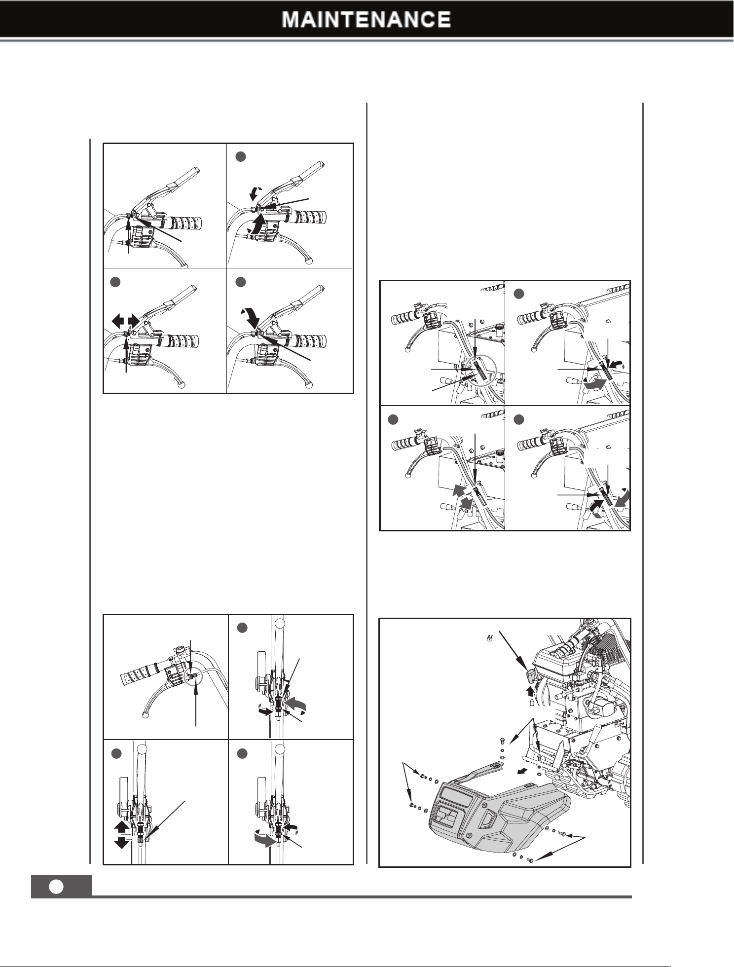
Adjusting Clutch
When the clutch begins to show wear, the
handle reach will become wider, making it
more difficult to reach. Follow these steps
to return the clutch lever back to its original
position.
1. Loosen the jam nut by turning it counter
clockwise with 10 mm wrench.
2. Tighten or loosen the cable by turning the
cable adjustment nut clockwise or counter
clockwise with 10 mm wrench until you have
reached your required tightness.
MAINTENANCE
Maintaining your mini tracked dumper will
ensure long life to the machine and its
components.
Preventive Maintenance
1. Turn off the engine and disengage all
command levers. The engine must be cool.
2. Keep the engine’s throttle lever in its SLOW
position and remove the spark plug wire
from the spark plug and secure.
3. Inspect the general condition of the mini
tracked dumper. Check for loose screws,
misalignment or binding of moving parts,
cracked or broken parts, and any other
condition that may affect its safe operation.
4. Use a soft brush, vacuum or compressed
air to remove all contaminants from the
machine. Then use high quality light oil to
lubricate all moving parts.
5. Replace the spark plug wire.
Never use a “pressure washer” to
clean your unit. Water can penetrate
tight areas of the machine and its
transmission case and cause damage
to spindles, gears, bearings, or the
engine. The use of pressure washers
will result in shortened life and
reduce serviceability.
09737UK00M100_更新回收处理标志.indd 13 2019/9/4 11:01:34
MINI TRACKED DUMPER
14
GB
3. Once tightness is set, return the jam nut
against the handle to hold the cable in place.
Jam Nut
Adjustment Nut
Adjustment Nut
Jam Nut
Jam Nut
1
2 3
1
Jam Nut
Lock Nut
2 3
Jam Nut
Adjustment Nut
Adjustment Nut
Jam Nut
1
32
Jam Nut
Lock Nut
Adjustment
Nut
Lock Nut
Adjustment Nut
Jam Nut
Jam Nut
Lock Nut
Adjusting Steering
If steering becomes difficult to engage follow
these steps to adjust the cable tension.
1. Loosen the jam nut by turning it counter
clockwise with 10 mm wrench.
2. Tighten or loosen the cable by turning the
cable adjustment nut clockwise or counter
clockwise with 10 mm wrench until you have
reached your required tightness.
3. Once tightness is set, return the jam nut
against the handle to hold the cable in place.
If the above adjustment does not create
enough cable tension, follow the steps below:
1. Loosen the jam nut by turning it counter
clockwise with 12mm wrench.
2. Tighten or loosen the cable by turning the
cable adjustment nut clockwise or counter
clockwise with 10 mm wrench until you have
reached your required tightness.
3. Once tightness is set, return the jam nut
against the handle to hold the cable in place.
Replacing Drive Belt
Remove the knob of the gear selection handle.
Loosen the six M8x20 screws and washers
and take off the guard.
Gear Selection Handle
M8×20 (×2)
M8×20 (×2)
M8×20 (×2)
09737UK00M100_更新回收处理标志.indd 14 2019/9/4 11:01:41

MINI TRACKED DUMPER
15
GB
Lubrication
General Lubrication
Lightly lubricate all moving parts of the
machine at end of the season or every 25
operating hours.
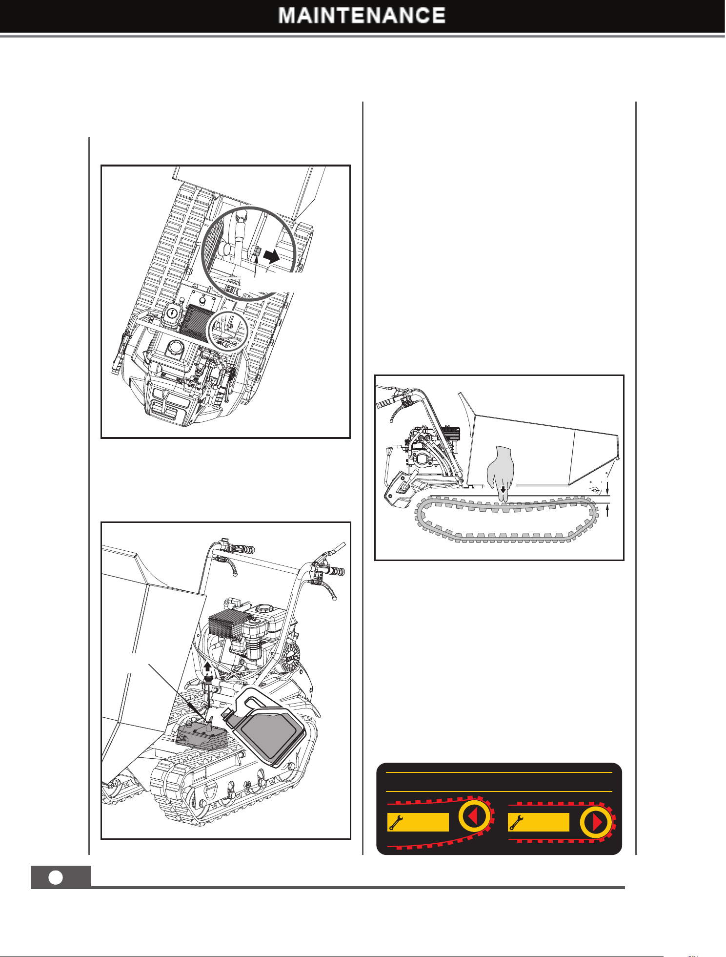
Gearbox Lubrication
The gearbox is pre-lubricated and sealed
at the factory. Unless there is evidence of
leakage or service has been performed on the
gearbox, no additional lubricate should be
required until 50 hours use.
After first 50 hours use, change all the gear oil.
Capacity is 1.5L.
For future use, check the oil level after every
50 hours of use. If you remove the oil level
plug and no oil flows out, please add oil and
then screw the oil level plug.
Gear oil GL-5 or GL-6, SAE80W-90 is
recommended. Do not use synthetic oil.
When replacing gear oil, the engine must be
stopped and still warm. Unscrew the filter
cap and the drain plug. When oil is drained,
replace the drain plug, fill up with fresh oil, and
then replace the filter cap.
Remove all the screws and washers from both
belt covers and take off the covers.
Dismount the two M10X25 bolts and washers
and remove the pump with flange.
Dismount the three M6x12 screws and washers
and remove the hydraulic valve and its
mounting plate.
Turn the gearbox pulley and pull out the drive
belt.
M8×16 (×2)
M8×20 (×1)
M6×12 (×2)
Belt Cover
M6×12 (×2)
M6×12 (×1)
Drive Belt
Pump with Flange
M10×25 (×2)
Oil Outlet
09737UK00M100_更新回收处理标志.indd 15 2019/9/4 11:01:44
MINI TRACKED DUMPER
16
GB
Remove the oil dipstick and add the oil. The
recommended hydraulic oil is 10W AW32,
ASLE H-150, or ISO 32. Oil capacity of the
hydraulic system is 3.5L
Hydraulic Oil
Unscrew the locking nut to drain the oil into
the pan.
Tightening Tracks
With use, tracks tend to loosen. When
operating with loose tracks, they tend to slip
over the driving wheel causing it to jump its
housing, thus damaging wear to the housing.
To check track tightness, proceed as follows.
1. Set the machine on a flat surface with
compact ground, or on asphalt or pavement.
2. Lift the machine and set it on blocks or
supports rated for the weight of the machine
so that the tracks are approximately 10 cm
off the ground.
3. Measure the track midline vs. the horizontal
line. The reading must not be more than 10
~ 15 mm.
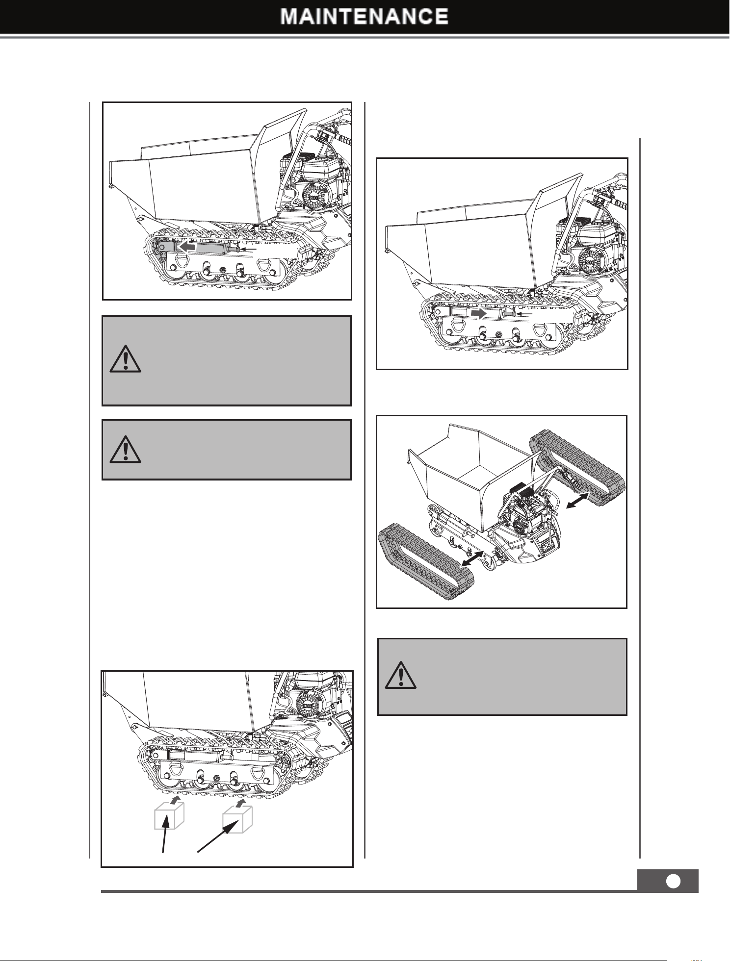
If the distance is greater, proceed as follows.
1. Use the tipping handle to tip the hopper
and set it on blocks or supports rated for
the weight of the box.
2. Loosen locknut A.
3. Tighten bolt B until the correct tightness is
restored.
4. Secure bolt B by tightening locknut A
thoroughly.
5. Return the hopper to its original position.
M14 x 1.5
Oil Filler
10 ~ 15 mm
TRACKED TENSION ADJUSTMENT
LOOSEN TIGHTEN
09737UK00M100_更新回收处理标志.indd 16 2019/9/4 11:01:48
MINI TRACKED DUMPER
17
GB
If the adjustment bolt has no more
adjustment left, the tracks may have
to be replaced.
Caution: Do not over-tighten your
track. The adjustment of the track
and the brakes are linked. The
braking power will lessen the more
the track is tightened.
Replacing Tracks
Check the condition of the tracks periodically.
If any track is cracked or frayed, it should be
replaced as soon as convenient.
1. Lift up the hopper and insert a support rod
for safety purposes.
2. Lift the machine and set it on blocks or
supports rated for the weight of the machine
so that the tracks are approximately 10 cm
off the ground.
Support Object
M20×180
M20×180
ENGINE MAINTENANCE
Refer to the Engine Manual included in
your unit for the information on engine
maintenance. Your engine manual provides
detailed information and a maintenance
schedule for performing the tasks.
When removing or installing the
tracks, be careful not to get your
fingers caught between the track
and pulley.
Adjust the bolt M20x180 to move the guiding
wheel assembly toward the driving wheels.
Then the track will get loose.
Pull out the loosen tracks .
09737UK00M100_更新回收处理标志.indd 17 2019/9/4 11:01:51
MINI TRACKED DUMPER
18
GB
5. Inspect for any loose or damaged parts.
Repair or replace damaged parts and
tighten loose screws, nuts or bolts.
6. Store your unit on flat ground in a clean, dry
building that has good ventilation.
STORAGE
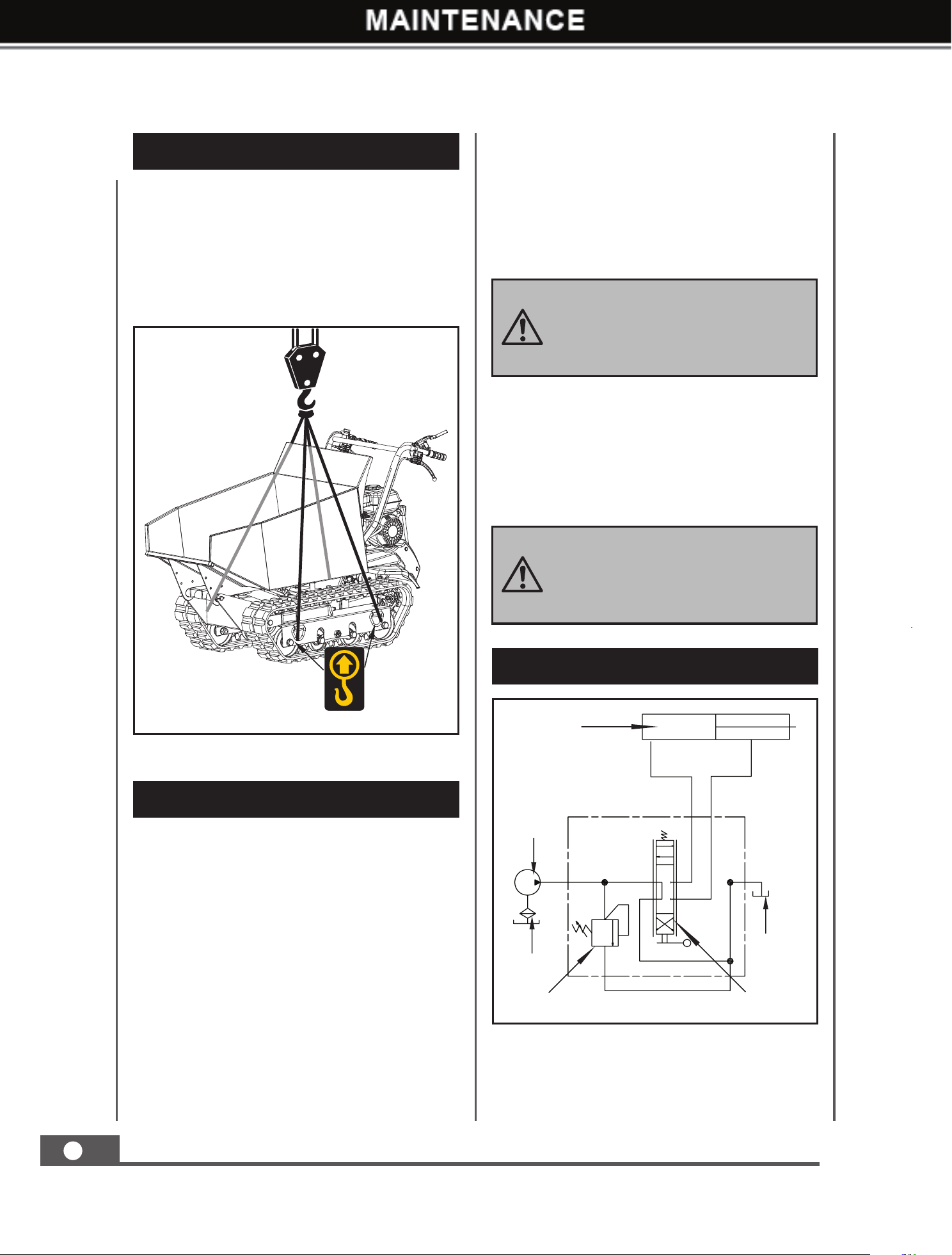
Transporting
HYDRULIC SCHEME
If the mini tracked dumper will not be used for
a period longer than 30 days, follow the steps
below to prepare your unit for storage.
1. Drain the fuel tank completely. Stored fuel
containing ethanol or MTBE can start to go
stale in 30 days. Stale fuel has high gum
content and can clog the carburetor and
restrict fuel flow.
2. Start the engine and run until it stops. This
helps prevent gum deposits from forming
inside the carburetor and possible engine
damage.
3. While the engine is still warm, drain the oil
Do not use strong detergents or
petroleum based cleaners when
cleaning plastic parts. Chemicals
can damage plastics.
Do not store the machine with fuel
in a non-ventilated area where fuel
fumes may reach flame, sparks,
pilot lights or any ignition sources.
Oil Cylinder
Oil Pump
A
P
T
B
(25MP, 2.5ml/r)
Oil Tank
Reversal Valve
Oil Filter
Oil Relief Valve
from the engine. Refill with fresh oil of the
grade recommended in the Engine Manual.
4. Use clean cloths to clean off the outside of
the machine and to keep the air vents free
of obstructions.
For long distance transport, the machine is
equipped with lifting rings for hoist.
Use a crane to lift up the machine with a
reliable chain, rope or strap fixed through the
lifting rings as shown in the figure.
09737UK00M100_更新回收处理标志.indd 18 2019/9/4 11:01:53
MINI TRACKED DUMPER
19
GB
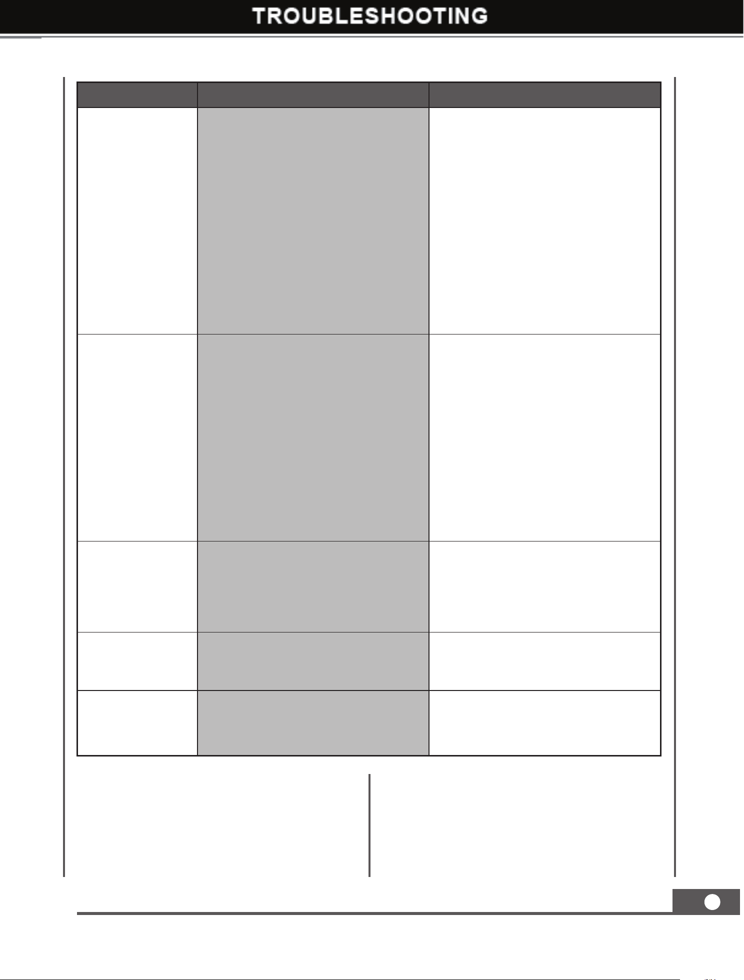
TROUBLE SHOOTING
Problem Cause Remedy
Engine fails to
start
1. Spark plug wire is disconnected
2. Out of fuel or stale fuel
3. Engine and/or Fuel valve is not in
ON position
4. Choke lever is not in CLOSE
position
5. Blocked fuel line
6. Fouled spark plug
7. Engine flooding
8. Belt tension lever is engaged
1. Attach spark plug wire securely
to spark plug
2. Fill with clean, fresh gasoline
3. Engine and Fuel valve must be in
ON position
4. Choke level must be in CLOSE
position for a cold start
5. Clean fuel line
6. Clean, adjust gap, or replace
7. Wait a few minutes to restart, but
do not prime
8. Disengage the belt tension lever
Engine runs
erratically
1. Spark plug wire is loose
2. Unit running with Choke lever in
CLOSE position
3. Blocked fuel line or stale fuel
4. Vent plugged
5. Water or dirt in fuel system
6. Dirty air cleaner
7. Improper carburetor adjustment
1. Connect and tighten spark plug
wire
2. Move choke lever to OPEN
position
3. Clean fuel line. Fill tank with
clean, fresh gasoline
4. Clear vent
5. Drain fuel tank. Refill with fresh
fuel
6. Clean or replace air cleaner
7. Refer to engine manual
Engine overheats
1. Engine oil level low
2. Dirty air cleaner
3. Air flow restricted
4. Carburetor not adjusted properly
1. Fill crankcase with proper oil
2. Clean air cleaner
3. Remove housing and clean
4. Refer to engine manual
One of the two
tracks is blocked
Foreign bodies have worked their
way between the track and the frame
Remove the foreign body
Machine does not
move while engine
is running
1. Gear is not properly selected
2. Driving tracks not tight enough
1. Ensure gear lever is not in-
between two different gears
2. Tighten driving tracks
09737UK00M100_更新回收处理标志.indd 19 2019/9/4 11:01:53
MINI TRACKED DUMPER
19
GB
TROUBLE SHOOTING
Problem Cause Remedy
Engine fails to
start
1. Spark plug wire is disconnected
2. Out of fuel or stale fuel
3.
Engine and/or Fuel valve is not in
ON position
4.
Choke lever is not in CLOSE
position
5. Blocked fuel line
6. Fouled spark plug
7. Engine flooding
8. Belt tension lever is engaged
1.
Attach spark plug wire securely
to spark plug
2. Fill with clean, fresh gasoline
3. Engine and Fuel valve must be in
ON position
4.
Choke level must be in CLOSE
position for a cold start
5. Clean fuel line
6. Clean, adjust gap, or replace
7.
Wait a few minutes to restart, but
do not prime
8. Disengage the belt tension lever
Engine runs
erratically
1. Spark plug wire is loose
2.
Unit running with Choke lever in
CLOSE position
3. Blocked fuel line or stale fuel
4. Vent plugged
5. Water or dirt in fuel system
6. Dirty air cleaner
7. Improper carburetor adjustment
1.
Connect and tighten spark plug
wire
2.
Move choke lever to OPEN
position
3.
Clean fuel line. Fill tank with
clean, fresh gasoline
4. Clear vent
5.
Drain fuel tank. Refill with fresh
fuel
6. Clean or replace air cleaner
7. Refer to engine manual
Engine overheats
1. Engine oil level low
2. Dirty air cleaner
3. Air flow restricted
4. Carburetor not adjusted properly
1. Fill crankcase with proper oil
2. Clean air cleaner
3. Remove housing and clean
4. Refer to engine manual
One of the two
tracks is blocked
Foreign bodies have worked their
way between the track and the frame
Remove the foreign body
Machine does not
move while engine
is running
1. Gear is not properly selected
2. Driving tracks not tight enough
1.
Ensure gear lever is not in-
between two different gears
2. Tighten driving tracks
09737UK00M100_更新回收处理标志.indd 19 2019/9/4 11:01:53
MINI TRACKED DUMPER
19
GB
TROUBLE SHOOTING
Problem Cause Remedy
Engine fails to
start
1. Spark plug wire is disconnected
2. Out of fuel or stale fuel
3. Engine and/or Fuel valve is not in
ON position
4. Choke lever is not in CLOSE
position
5. Blocked fuel line
6. Fouled spark plug
7. Engine flooding
8. Belt tension lever is engaged
1. Attach spark plug wire securely
to spark plug
2. Fill with clean, fresh gasoline
3. Engine and Fuel valve must be in
ON position
4. Choke level must be in CLOSE
position for a cold start
5. Clean fuel line
6. Clean, adjust gap, or replace
7. Wait a few minutes to restart, but
do not prime
8. Disengage the belt tension lever
Engine runs
erratically
1. Spark plug wire is loose
2. Unit running with Choke lever in
CLOSE position
3. Blocked fuel line or stale fuel
4. Vent plugged
5. Water or dirt in fuel system
6. Dirty air cleaner
7. Improper carburetor adjustment
1. Connect and tighten spark plug
wire
2. Move choke lever to OPEN
position
3. Clean fuel line. Fill tank with
clean, fresh gasoline
4. Clear vent
5. Drain fuel tank. Refill with fresh
fuel
6. Clean or replace air cleaner
7. Refer to engine manual
Engine overheats
1. Engine oil level low
2. Dirty air cleaner
3. Air flow restricted
4. Carburetor not adjusted properly
1. Fill crankcase with proper oil
2. Clean air cleaner
3. Remove housing and clean
4. Refer to engine manual
One of the two
tracks is blocked
Foreign bodies have worked their
way between the track and the frame
Remove the foreign body
Machine does not
move while engine
is running
1. Gear is not properly selected
2. Driving tracks not tight enough
1. Ensure gear lever is not in-
between two different gears
2. Tighten driving tracks
09737UK00M100_更新回收处理标志.indd 19 2019/9/4 11:01:53
MINI TRACKED DUMPER
20
GB
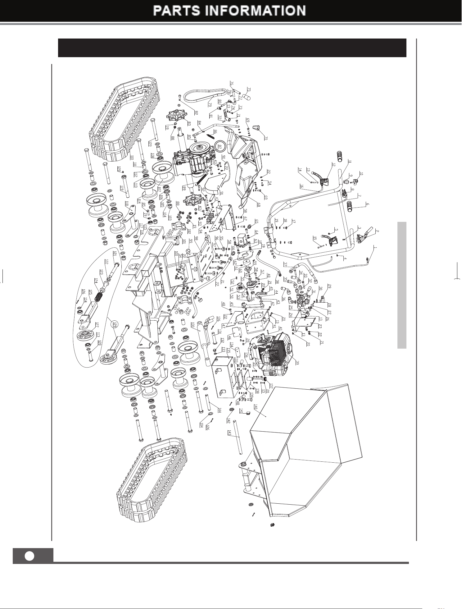
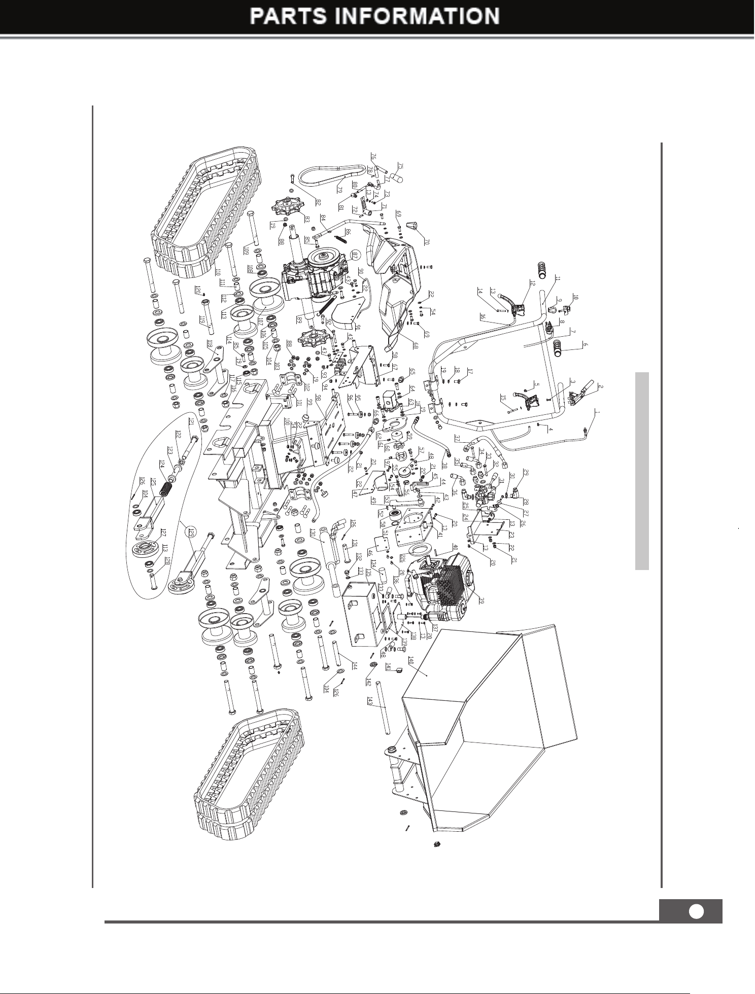
PARTS SCHEDULE
09737 Machine
09737UK00M100_更新回收处理标志.indd 20 2019/9/4 11:01:55
MINI TRACKED DUMPER
21
GB
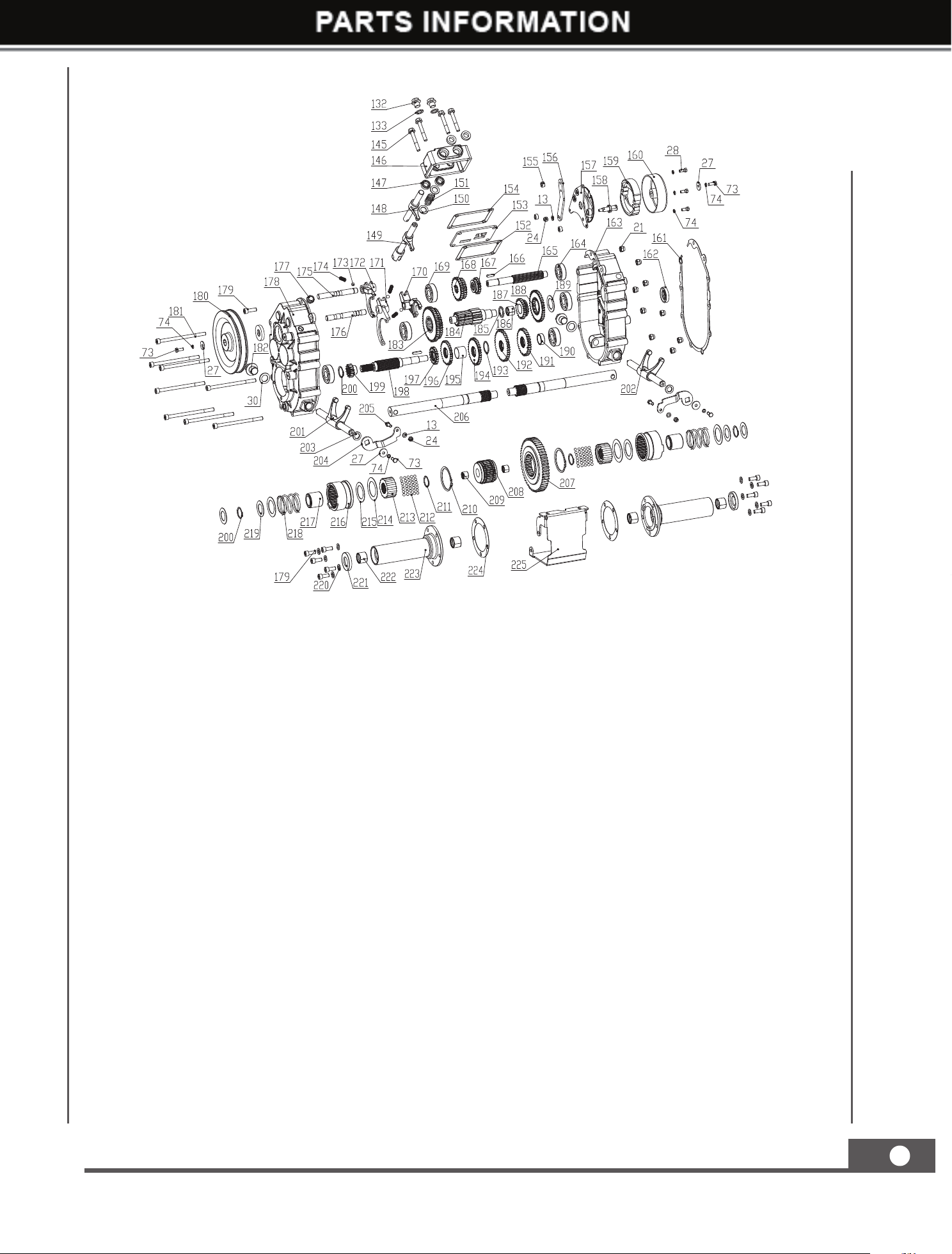
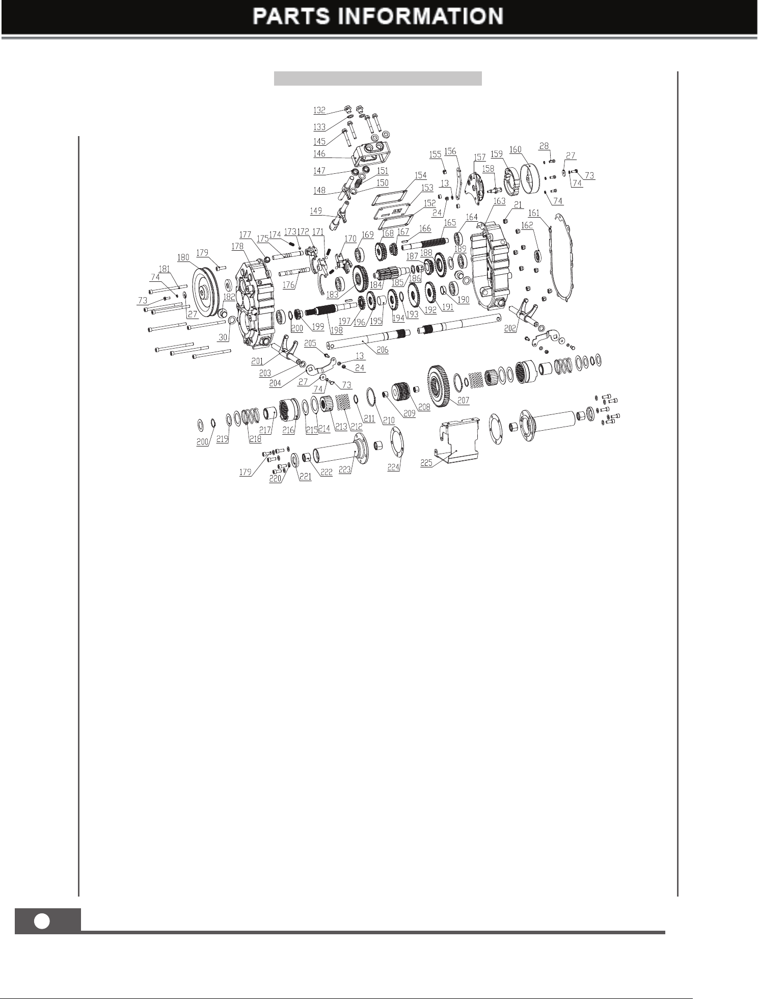
09737 Gearbox (50)
09737UK00M100_更新回收处理标志.indd 21 2019/9/4 11:01:57
MINI TRACKED DUMPER
20
GB
PARTS SCHEDULE
09737 Machine
09737UK00M100_更新回收处理标志.indd 20 2019/9/4 11:01:55
MINI TRACKED DUMPER
21
GB
09737 Gearbox (50)
09737UK00M100_更新回收处理标志.indd 21 2019/9/4 11:01:57
MINI TRACKED DUMPER
21
GB
09737 Gearbox (50)
09737UK00M100_更新回收处理标志.indd 21 2019/9/4 11:01:57
MINI TRACKED DUMPER
22
GB
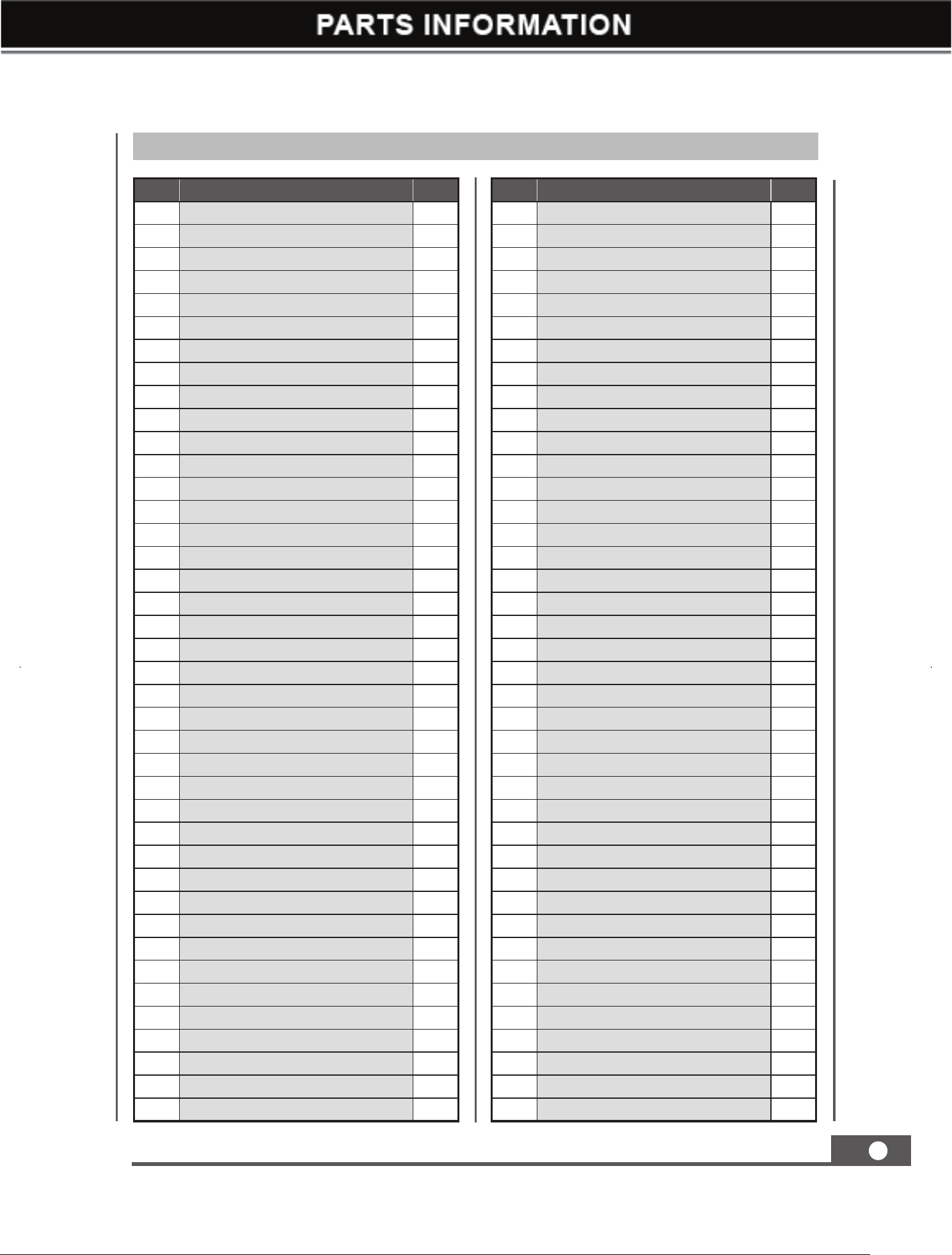
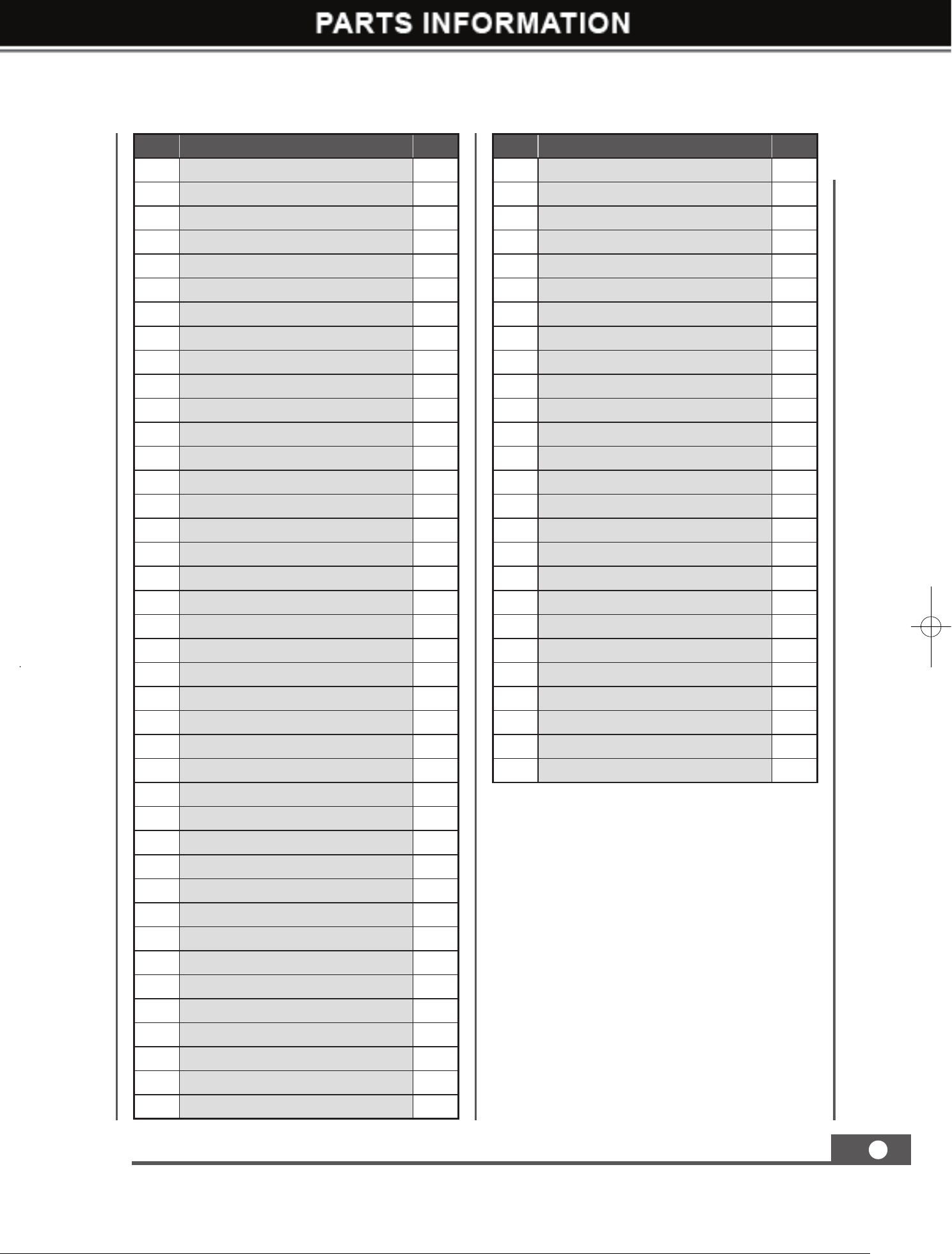
No. Description Q'ty
1 Clutch Control Lever Cable 1
2 Clutch Control Lever 1
3 Screw M6x16 1
4 Screw M5x20 2
5 Nut M5 2
6 Handle sleeve 2
7 Throttle Lever 1
8 Throttle Cable 1
9 Hoop 1
10 ON/OFF Switch 1
11 Handle Frame 1
12 Right/Left Steering Lever 2
13 Washer ø6 17
14 Screw M6x35 1
15 Screw M6x60 1
16 Steering Cable 2
17 Bolt M10x25 4
18 Washer ø10 8
19 Washer ø10 25
20 Bolt M6x12 13
21 Nut M8 18
22 Washer ø8 35
23 Mounting Plate 1
24 Nut M6 4
25 Return Plate 1
26 Torsional Spring 1
27 Washer 6 4
28 Screw M6
×
30 4
29 Angle Coupling G3/8-M18
×
1.5 2
30 Combined Sealing Washer 18 6
31 Reversing Valve 1
32
Thread Connector G3/8-M18X1.5
2
33 Bolt M8x55 2
34 Oil Inlet Hose of Cylinder 1
35 Oil Return Hose of Cylinder 1
36 Oril Return Hose 1
37 High Pressure Oil Inlet Pipe 1
38 Oil Drain Hose 1
39 Gasoline Engine 1
40 Flat Key 5x35 1
No. Description Q'ty
41 Pump Mounting Plate 1
42 Washer ø8 2
43 Bolt M8x16 5
44 Bolt M8x25 1
45 Belt Retaining Bracket I 1
46 Front Plate 1
47 Pulley Cover 1
48 Bolt M8x20 6
49 Tensioner Pulley Bracket 1
50 Tensioner Pulley 1
51 Circlip 35 1
52 Screw M5x12 1
53 Belt Retaining Bracket 1
54 Washer ø8 22
55 Bolt M8x30 1
56 Sleeve Washer 1
57 Small Pulley 1
58 Bolt M8x25 4
59 Rubber Gasket 1
60 Coupler(12.7) 1
61 Screw M8x10 w/glue 2
62 Pump Mounting Flange 1
63 Screw M10x25 4
64 Oil Pump CBQ-FT3.0(20MP) 1
65 NPT3/8-M18X1.5 2
66 Oil Suction Hose 1
67 Transition Plate 1
68 Gearbox Cover 1
69 Screw M8x20 6
70 Knob 1
71 Shaft Sleeve 1
72 Cylindrical Pin 6x25 1
73 Bolt M6x16 4
74 Spring washer 6 8
75 Hand Knob 1
76 Rocker 1
77 Elbow Lever 1
78 Cylindrical Pin 4x14 1
79 V- Belt 32 1
80 Adjusting Shaft 1
Parts List
09737UK00M100_更新回收处理标志.indd 22 2019/9/4 11:01:58

MINI TRACKED DUMPER
23
GB
No. Description Q'ty
81 Knuckle Bearing SQ6-RS 2
82 Screw M10x60 2
83 Driving Wheel 2
84 Gear Shifting Lever 1
85 Bolt M10x35 3
86 Spring 1
87 Gearbox 6+2 1
88 Lock Nut M10 13
89 Long Extension Sping 1
90 Brake Cable 1
91 Big Pulley Cover 1
92 Bolt M8x60 2
93 Pressing Plate 1
94 Hose Clamp 1
95 Rubber Pad 4
96 Bolt M8x45 4
97 Cable Bracket
1
98 Chassis Weldment 1
99
Rubber Cushion
4
100 Nut M8 1
101 Bolt M10x65 8
102 Axle Pressing Plate 2
103 Nut M20 8
104 Washer 20 20
105 Support Bush 1 8
106 Seal FB25
×
47
×
7 8
107 Supportin Wheel 4
108 Bearing 6204-2RS 8
109 Hexagon Bolt 8
110 Track 180x60 38 2
111 Support Bush 2 8
112 Seal FB25x42x7 8
113 Bearing 6004-2RS 12
114 Supportin Wheel 4
115 Bearing 6300-2RS 2
116 Nut M22 2
117 Washer 22 2
118 Wheel Mounting Bracker 2
119 Bolt M22x180 2
120 Grease Nipple 6x1 2
No. Description Q'ty
121 Adjusting Shaft 2
122 Hexagon Thin Nut M20 2
123 Connecting Pipe 2
124 Guide Spring 2
125 Guide Wheel Adjusting Part 2
126 Cotter Pin
∮
4X35 7
127 Guide Wheel 2
128 Axis Pin 2
129 Guide Wheel Assy. 2
130 Rotation Shaft 1 1
131 Axis Pin 20x95 1
132 Plug M14x1.5 3
133 Combined Sealing Washer 14 8
134 Oil Filter 1
135 Oil Tank 1
136 Hollow Bolt M14x1.5 2
137 Oil Dipsticker 1
138 Oil Tank Cover 1
139 Asbestos Cushion 1
140 Dumper Box 1
141 Pipe Plug 19x19 2
142 Elastic Cushion 2
143 Two-head Stud 1
144 Rotation Shaft 2 1
145 Hexagon Flange Bolt M8x55 4
146 Gear Shift Tower 1
147 Seal FB14x24x7 4
148 Speed Shift Pin + Pin Axis 1
149 Gear Shift Pin + Pin Axis 1
150 Compression Spring 1
151 Washer 2
152
Paper Spacer for Gear Shift Plate
1
153 Gear Shift Plate 1
154
Paper Spacer for Gear Shift Tower
1
155 Joint Bolt 3
156 Brake Pull Plate 1
157 Brake Fixing Part 1
158 Connecting Shaft 1
159 Brake Shoe 1
160 Expansion Brake Cover 1
09737UK00M100_更新回收处理标志.indd 23 2019/9/4 11:01:58
MINI TRACKED DUMPER
24
GB
No. Description Q'ty
161 Paper Spacer for Housing 1
162 Seal FB17X40X7 2
163 Gearbox Housing ( L) 1
164 Bearing 6302 1
165 Spline Shaft 1
166 Key A5x20 2
167 Gear 1 / R 1
168 Gear 2 / 3 1
169 Bearing 6303 5
170
Shifting Fork - Gear 1/R
1
171 Shifting Fort - Speed H/L 1
172 Shifting Fork - Gear 2/3 1
173 Steel Ball 3
174 Positionning Spring 3
175 Shift Fork Shaft I 1
176 Shift Fork Shaft II 1
177 Vent Plug 1
178 Gearbox Housing ( R) 1
179 Screw M8x25 11
180 Large Belt Pulley
1
181 Screw M8X130 8
182 Plug Screw M18x1.5 2
183 Gear - Speed H/L 1
184 Intermediate Shaft II 1
185 Anti-wear Gasket II 1
186 Gear
Ⅲ
-2 Bush 1
187 Transition Gear for Reverse 1
188
Driven Gear for Reverse
1
189 Anti-wear Gasket I 1
190 Bush 1 1
191 Gear
Ⅱ
-4 1
192 Driven Gear for Gear 1 1
193 Adjusting Pad(27
×
34
×
1.5) 1
194 Driven Gear for Gear 2 1
195 Bush 2 1
196 Driven Gear for Gear 3 1
197 Driving Gear for Speed H 1
198 Intermediate Shaft I 1
199 Driving Gear for Speed L 1
200 Circlip 26 3
No. Description Q'ty
201 Clutch Fork (R) 1
202 Clutch Fork Shaft (L) 1
203 Seal FB16x22x4 2
204 Swing Plate 2
205 Bolt M6X20 2
206 Output Shaft 2
207 Output Big Gear 1
208 Intermediate Joint Bush 1
209
Intermediate Joint Bush Composite Bushing
2
210
Circlip 58
2
211 Circlip 25 2
212 Steel Ball 5 70
213 Joint Bush 2
214 Spring Gasket 2
215 Spring Gasket 4
216 Clutch Sleeve 2
217 Spring Guide Bush 2
218 Clutch Spring 2
219 Gasket 1 4
220 Washer 8 10
221 Seal FB25x42x7 2
222
Output Shaft Composite Bushing
4
223 Outpush Shaft Bush 2
224 Paper Gasket for Bush 2
225 Guard Cover 1
09737UK00M100_更新回收处理标志.indd 24 2019/9/4 11:01:58
MINI TRACKED DUMPER
25
GB
09737A Machine
09737UK00M100_更新回收处理标志.indd 25 2019/9/4 11:02:01
MINI TRACKED DUMPER
26
GB
09737A Gearbox (50)
09737UK00M100_更新回收处理标志.indd 26 2019/9/4 11:02:03
MINI TRACKED DUMPER
27
GB
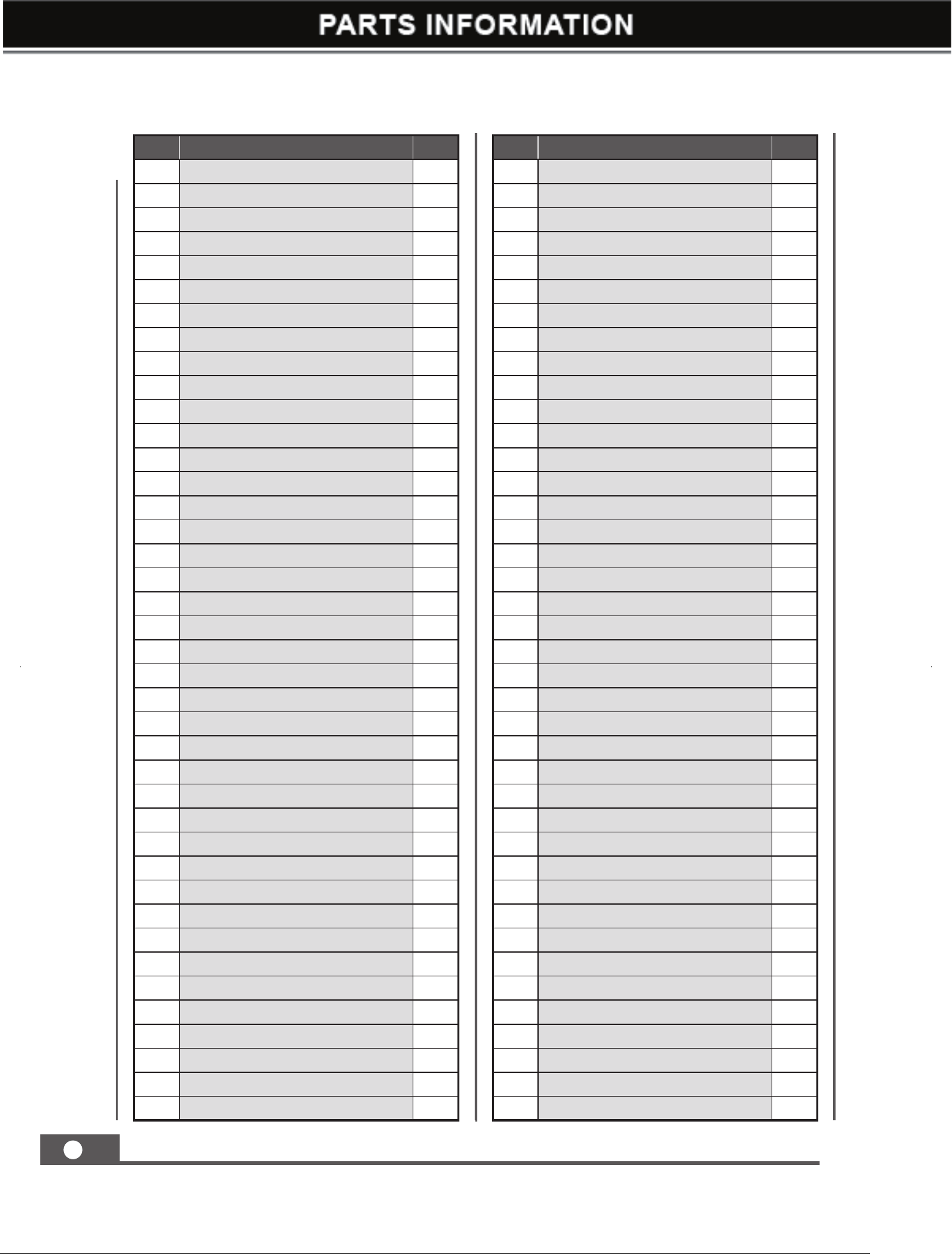
No. Description Q'ty
1 Clutch Control Lever Cable 1
2 Clutch Control Lever 1
3 Screw M6x16 1
4 Screw M5x20 2
5 Nut M5 2
6 Handle sleeve 2
7 Throttle Lever 1
8 Throttle Cable 1
9 Hoop 1
10 ON/OFF Switch 1
11 Handle Frame 1
12 Right/Left Steering Lever 2
13 Washer ø6 17
14 Screw M6x35 1
15 Screw M6x60 1
16 Steering Cable 2
17 Bolt M10x25 4
18 Washer ø10 8
19 Washer ø10 25
20 Bolt M6x12 13
21 Nut M8 18
22 Washer ø8 35
23 Mounting Plate 1
24 Nut M6 4
25 Return Plate 1
26 Torsional Spring 1
27 Washer 6 4
28 Screw M6
×
30 4
29 Angle Coupling G3/8-M18
×
1.5 2
30 Combined Sealing Washer 18 6
31 Reversing Valve 1
32
Thread Connector G3/8-M18X1.5
2
33 Bolt M8x55 2
34 Oil Inlet Hose of Cylinder 1
35 Oil Return Hose of Cylinder 1
36 Oril Return Hose 1
37 High Pressure Oil Inlet Pipe 1
38 Oil Drain Hose 1
39 Gasoline Engine 1
40 Flat Key 7x40 1
No. Description Q'ty
41 Pump Mounting Plate 1
42 Washer ø8 2
43 Bolt M8x16 5
44 Bolt M8x25 1
45 Belt Retaining Bracket I 1
46 Front Plate 1
47 Pulley Cover 1
48 Bolt M8x20 6
49 Tensioner Pulley Bracket 1
50 Tensioner Pulley 1
51 Circlip 35 1
52 Screw M5x12 1
53 Belt Retaining Bracket 1
54 Washer ø8 22
55 Bolt M8x30 1
56 Sleeve Washer 1
57 Small Pulley 1
58 Bolt M8x25 4
59 Rubber Gasket 1
60 Coupler(12.7) 1
61 Screw M8x10 w/glue 2
62 Pump Mounting Flange 1
63 Screw M10x25 4
64 Oil Pump CBQ-FT3.0(20MP) 1
65 NPT3/8-M18X1.5 2
66 Oil Suction Hose 1
67 Transition Plate 1
68 Gearbox Cover 1
69 Screw M8x20 6
70 Knob 1
71 Shaft Sleeve 1
72 Cylindrical Pin 6x25 1
73 Bolt M6x16 4
74 Spring washer 6 8
75 Hand Knob 1
76 Rocker 1
77 Elbow Lever 1
78 Cylindrical Pin 4x14 1
79 V- Belt B32 1
80 Adjusting Shaft 1
Parts List
09737UK00M100_更新回收处理标志.indd 27 2019/9/4 11:02:03
MINI TRACKED DUMPER
28
GB
No. Description Q'ty
81 Knuckle Bearing SQ6-RS 2
82 Screw M10x60 2
83 Driving Wheel 2
84 Gear Shifting Lever 1
85 Bolt M10x35 3
86 Spring 1
87 Gearbox 6+2 1
88 Lock Nut M10 13
89 Long Extension Sping 1
90 Brake Cable 1
91 Big Pulley Cover 1
92 Bolt M8x60 2
93 Pressing Plate 1
94 Hose Clamp 1
95 Rubber Pad 4
96 Bolt M8x45 4
97 Coupler (%c25) 1
98 Chassis Weldment 1
99
Rubber Cushion
4
100 Nut M8 1
101 Bolt M10x65 8
102 Axle Pressing Plate 2
103 Nut M20 8
104 Washer 20 20
105 Support Bush 1 8
106 Seal FB25
×
47
×
7 8
107 Supportin Wheel 4
108 Bearing 6204-2RS 8
109 Hexagon Bolt 8
110 Track 180x60 38 2
111 Support Bush 2 8
112 Seal FB25x42x7 8
113 Bearing 6004-2RS 12
114 Supportin Wheel 4
115 Bearing 6300-2RS 2
116 Nut M22 2
117 Washer 22 2
118 Wheel Mounting Bracker 2
119 Bolt M22x180 2
120 Grease Nipple 6x1 2
No. Description Q'ty
121 Adjusting Shaft 2
122 Hexagon Thin Nut M20 2
123 Connecting Pipe 2
124 Guide Spring 2
125 Guide Wheel Adjusting Part 2
126 Cotter Pin
∮
4X35 7
127 Guide Wheel 2
128 Axis Pin 2
129 Guide Wheel Assy. 2
130 Rotation Shaft 1 1
131 Axis Pin 20x95 1
132 Plug M14x1.5 3
133 Combined Sealing Washer 14 8
134 Oil Filter 1
135 Oil Tank 1
136 Hollow Bolt M14x1.5 2
137 Oil Dipsticker 1
138 Oil Tank Cover 1
139 Asbestos Cushion 1
140 Dumper Box 1
141 Pipe Plug 19x19 2
142 Elastic Cushion 2
143 Two-head Stud 1
144 Rotation Shaft 2 1
145 Hexagon Flange Bolt M8x55 4
146 Gear Shift Tower 1
147 Seal FB14x24x7 4
148 Speed Shift Pin + Pin Axis 1
149 Gear Shift Pin + Pin Axis 1
150 Compression Spring 1
151 Washer 2
152
Paper Spacer for Gear Shift Plate
1
153 Gear Shift Plate 1
154
Paper Spacer for Gear Shift Tower
1
155 Joint Bolt 3
156 Brake Pull Plate 1
157 Brake Fixing Part 1
158 Connecting Shaft 1
159 Brake Shoe 1
160 Expansion Brake Cover 1
09737UK00M100_更新回收处理标志.indd 28 2019/9/4 11:02:03
MINI TRACKED DUMPER
29
GB
No. Description Q'ty
161 Paper Spacer for Housing 1
162 Seal FB17X40X7 2
163 Gearbox Housing ( L) 1
164 Bearing 6302 1
165 Spline Shaft 1
166 Key A5x20 2
167 Gear 1 / R 1
168 Gear 2 / 3 1
169 Bearing 6303 5
170
Shifting Fork - Gear 1/R
1
171 Shifting Fort - Speed H/L 1
172 Shifting Fork - Gear 2/3 1
173 Steel Ball 3
174 Positionning Spring 3
175 Shift Fork Shaft I 1
176 Shift Fork Shaft II 1
177 Vent Plug 1
178 Gearbox Housing ( R) 1
179 Screw M8x25 11
180 Large Belt Pulley
1
181 Screw M8X130 8
182 Plug Screw M18x1.5 2
183 Gear - Speed H/L 1
184 Intermediate Shaft II 1
185 Anti-wear Gasket II 1
186 Gear
Ⅲ
-2 Bush 1
187 Transition Gear for Reverse 1
188
Driven Gear for Reverse
1
189 Anti-wear Gasket I 1
190 Bush 1 1
191 Gear
Ⅱ
-4 1
192 Driven Gear for Gear 1 1
193 Adjusting Pad(27
×
34
×
1.5) 1
194 Driven Gear for Gear 2 1
195 Bush 2 1
196 Driven Gear for Gear 3 1
197 Driving Gear for Speed H 1
198 Intermediate Shaft I 1
199 Driving Gear for Speed L 1
200 Circlip 26 3
No. Description Q'ty
201 Clutch Fork (R) 1
202 Clutch Fork Shaft (L) 1
203 Seal FB16x22x4 2
204 Swing Plate 2
205 Bolt M6X20 2
206 Output Shaft 2
207 Output Big Gear 1
208 Intermediate Joint Bush 1
209
Intermediate Joint Bush Composite Bushing
2
210
Circlip 58
2
211 Circlip 25 2
212 Steel Ball 5 70
213 Joint Bush 2
214 Spring Gasket 2
215 Spring Gasket 4
216 Clutch Sleeve 2
217 Spring Guide Bush 2
218 Clutch Spring 2
219 Gasket 1 4
220 Washer 8 10
221 Seal FB25x42x7 2
222
Output Shaft Composite Bushing
4
223 Outpush Shaft Bush 2
224 Paper Gasket for Bush 2
225 Guard Cover 1
226 Locating Sleeve
1
09737UK00M100_更新回收处理标志.indd 29 2019/9/4 11:02:04

OF NOTE
PLEASE READ THE FOLLOWING CAREFULLY
THE
Record
Product"s Serial Number Here: __________________ _
Note: If product has no serial nuhlber, record month and year of purchase instead.
Note: Sohle parts are I isted and shO\,Vn for illustration purposes only and are
not
available
individually as replacement parts.
Questions, issues or missing parts?
Be
tore returning to your retaile-r
1
our
customer ser;, ice tearr is
here
to tie Ip,
MADE IN CHINA