REV C DATE: 07/25/2023
USER MANUALS\21-29415_GROCERANT_USER MANUAL_FB(L)SS-(N)7QN_FBI(L)SS-(N)7QN_SOUP WELL_FOOD BAR
SCC P/N
21-29415
USER
MANUAL
GROCERANT
CAREFULLY FOLLOW THESE INSTRUCTIONS
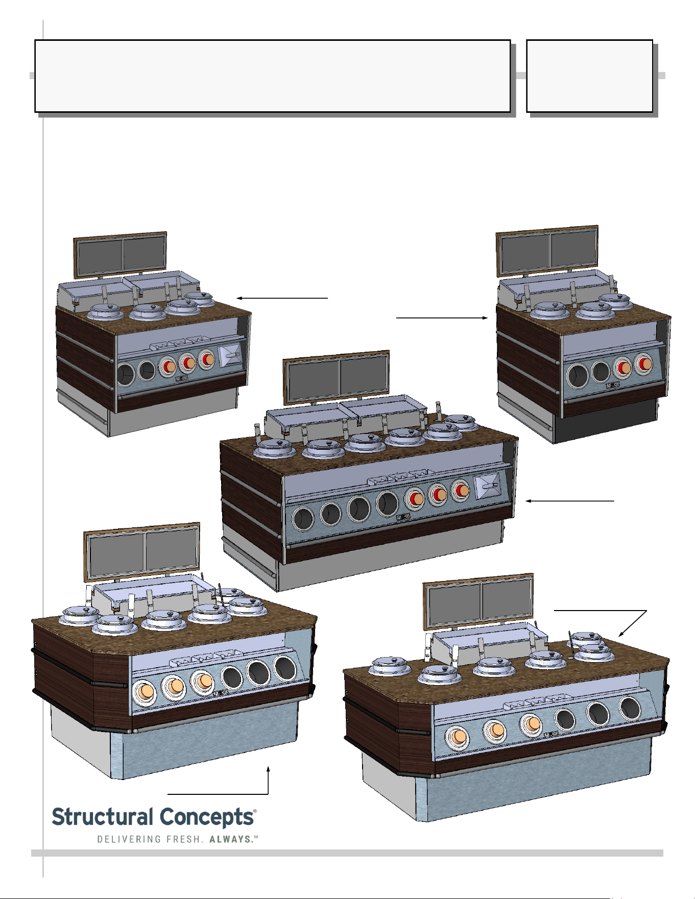
GROCERANT FB(L)SS-(N)7Q.8098 INDUCTION SOUP WELL & SOUP SIGNAGE BAR MERCHANDISERS
> This Manual Includes “In-Line” Units and “Island” Units (AKA “End Cap” Units)
> Units Include Quartz Solid Surface, Signage Bar, Vollrath® Induction 7-Quart Induction Soup Wells
(With Urns, Lids & Ladles), Sign Holders, Cup and Lid Dispensers, Condiment Holders/Dividers
> Each Soup Well is Controlled With Thermostat Accessible at Front of Case (Via Flip-Down Panel)
> “In-Line” Models Include: FB3SS-37QN.8098, FB4SS-47QN and FB6SS-67QN.8098
> “Island” (AKA “End Cap”) Models Include: FBI6SS-67QN.8099, FBI6SS-67QN.8100 and FBI7SS-67QN.8100
In-Line Model
FB4SS-47QN.8098
In-Line Model
FB3SS-37QN.8098
In-Line Model
FB6SS-67QN.8098
Island Model
FBI6SS-67QN.8099
Island Model
FBI7SS-67QN.8100
Structural Concepts Corp. ∙ 888 E. Porter Rd ∙ Muskegon, MI 49441 Phone: 231.798.8888 Fax: 231.798.4960 ∙ www.structuralconcepts.com

TABLE OF CONTENTS
2
TABLE OF CONTENTS ..…………………………………………………………………………………...…..
OVERVIEW / TYPE / COMPLIANCE / WARNINGS / WIRING / GFCI / SOUP WELLS ……………......
COMPONENT REMOVAL AND REPLACEMENT SECTION FOR IN-LINE CASES …………………...
COMPONENT REMOVAL: IN-LINE CASES ………………………………………………………………...
CASE REMOVAL FROM SKID: IN-LINE CASES ………………………………...………………………...
COMPONENT REPLACEMENT: IN-LINE CASES .………………………………………………….……...
VIEW OF CASE AFTER COMPONENT ATTACHMENT: IN-LINE CASES ……………………………...
COMPONENT REMOVAL AND REPLACEMENT SECTION FOR ISLAND / “END CAP” CASES ….
COMPONENT REMOVAL: ISLAND (AKA “END CAP”) CASES ………………………………………...
CASE REMOVAL FROM PALLET: ISLAND (AKA “END CAP”) CASES ……………………………….
COMPONENT REPLACEMENT: ISLAND (AKA “END CAP”) CASES ………………………………….
VIEW OF CASE AFTER COMPONENT ATTACHMENT: ISLAND (AKA “END CAP”) CASES ………...
GENERAL LAYOUT - GENERAL LAYOUT - SOUP SIGNAGE BAR / DISPENSERS / SOUP
WARMERS / CONDIMENT CONTAINERS ………………...……………………………………….
GENERAL LAYOUT, CONT’D - SOUP SIGNAGE BAR SYSTEM PIECES ..…………………………...
GENERAL LAYOUT, CONT’D - ENERGIZING CASE / WELLS ON & OFF SWITCH /
THERMOSTATS ………………………………………………………………………………………...
GENERAL LAYOUT, CONT’D - FIELD ACCESS BOX / ELECTRICAL OUTLETS / PACEMAKER
WARNING …………………………………………………………………………………………………
GENERAL LAYOUT, CONT’D DISPENSE-RITE CUP DISPENSER ADJUSTMENT INSTRUCTIONS
VOLLRATH® INDUCTION WARMERS - MODEL / SPECS / DESCRIPTION / CRITERIA /
FEATURES ………………………………………………………………………………………………
VOLLRATH® INDUCTION WARMERS - SAFETY PRECAUTIONS / OPERATION / WARNINGS .....
VOLLRATH® INDUCTION WARMERS - CONTROL PANEL / HOT FOOD HOLDING / SETTING
TEMPERATURE ………………………………………………………………………………………..
VOLLRATH® INDUCTION WARMERS - CLEANING …………………………….………..………..……..
VOLLRATH® INDUCTION WARMERS - TROUBLESHOOTING ………………………………………...
CLEANING SCHEDULE - GENERAL (DAILY / WEEKLY / MONTHLY) ….…………..………….……...
CLEANING & MAINTENANCE of ENGINEERED (SYNTHETIC) QUARTZ CARE AND
MAINTENANCE ………………………………………………………………………………..……….
TROUBLESHOOTING - GENERAL CASE ISSUES (FOR TRAINED SERVICE PERSONNEL ONLY)
SERIAL LABEL INFORMATION & LOCATION …………………..……………………………………..….
TECHNICAL SERVICE CONTACT INFORMATION / WARRANTY INFORMATION …....……..…..….
2
3-4
5
6
7
8
9
10
11
12
13
14
15
16
17
18
19
20
21
22
23
24
25
26
27
28
29
3 3
GENERAL OVERVIEW
• These Structural Concepts cases should be installed and
operated according to these instructions to ensure proper
performance. Improper use will void warranty.
• This unit is designed to display of products in ambient
store conditions with a max. temperature of 80 °F (27 °C).
SOUP WARMER OVERVIEW
• See VOLLRATH® INDUCTION WARMERS section in
this User Manual for product temperature parameters.
Failure to heat food product properly may result in
serious health risks.
• These soup warmers are intended to rethermalize
refrigerated, previously cooked food and HOLD hot food at
safe temperatures.
ELECTRICAL HAZARD WARNING
Risk of electric shock.
Disconnect ALL ELECTRICAL SOURCES before servicing.
WARNING
ELECTRICAL
HAZARD
COMPLIANCE
This equipment MUST be installed in compliance with all applicable NEC,
federal, state and local electrical and plumbing codes.
• For hot food holding, food must be at proper serving
temperature when placed into the ‘drop-in’ warmer.
• This equipment is NOT designed to cook raw food.
COMPLIANCE
• Performance issues when in violation of applicable
NEC, federal, state or local electrical codes are not
covered by warranty. See below.
PRECAUTIONS
• Following are important precautions to prevent damage
to unit or merchandise. Read carefully!
CAUTION! POWER CORD AND PLUG MAINTENANCE
Risk of electric shock. If cord or plug becomes damaged,
replace only with cord and plug of same type.
CAUTION! GFCI BREAKER USE REQUIREMENT
If N.E.C. (National Electric Code) or your local code
requires GFCI (Ground Fault Circuit Interrupter) protection,
you MUST use a GFCI breaker in lieu of a GFCI receptacle.
OVERVIEW / COMPLIANCE / WARNINGS / PRECAUTIONS / WIRING DIAGRAM / CORDS & PLUGS
WARNING: This product can expose you to chemicals, including
Urethane (Ethyl Carbamate), which are known to the state of
California to cause cancer and birth defects or other reproductive
harm. For more information go to P65Warnings.ca.gov.
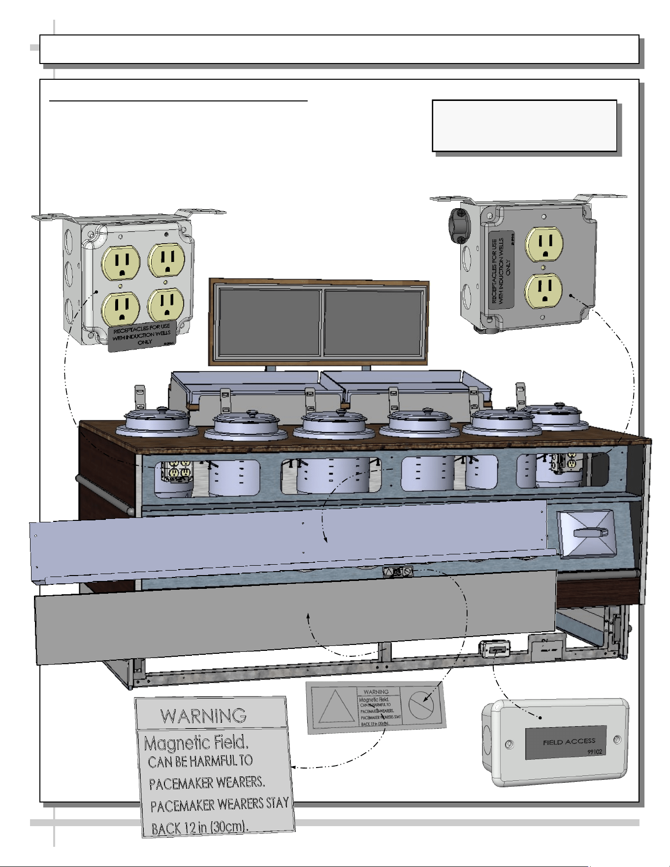
PACEMAKER WARNING!
Pacemakers must be kept at least 12” (30 cm) from heating areas
when using Vollrath® Warming System induction wells.
OVERVIEW / TYPE / COMPLIANCE / WARNINGS / WIRING / GFCI / SOUP WELLS - PAGE 2 of 2
4
WIRING DIAGRAM
• Each case has its own wiring diagram folded and in its
own packet.
• Wiring diagram placement may vary; it may be placed
near ballast box, field wiring box, raceway cover, or
other related location.
CAUTION! GFCI BREAKER USE REQUIREMENT
• N.E.C. (National Electric Code) or your local code
may require GFCI (Ground Fault Circuit Interrupter)
protection.
• In such cases, the use of a GFCI breaker is required.
INDUCTION WARMER SOUP WELL PRECAUTIONS
• Caution! Carefully follow the Vollrath® Drop-In
induction warmer soup well information in this User
Manual to prevent injury or damaging unit.
• Please read carefully!
OVERVIEW, TYPE, COMPLIANCE and WARNINGS
• See previous page for specifics on OVERVIEW, TYPE,
COMPLIANCE and WARNINGS.
WIRING DIAGRAM FORMAT & LOCATIONS
• Each case has its own wiring diagram folded and in its own packet.
• Wiring diagram placement may vary; it may be placed near ballast box, field
wiring box, raceway cover, or other related location.
• Wiring diagram for this unit is also provided in this manual. See TABLE OF
CONTENTS for location.
CAUTION! CAREFULLY FOLLOW THE VOLLRATH®
DROP-IN INDUCTION WARMER SOUP WELL
INFORMATION TO PREVENT INJURY OR DAMAGING UNIT
C A U T I O N !
888 E. PORTER ROAD, MUSKEGON, MI 49441
PHONE: (231) 798-8888 WWW.STRUCTURALCONCEPTS.COM
Concepts
Structural
Important SCC Note: This data is from Vollrath Operator’s Manual -
Part No. 2350231-1 ml 02/05/2020; it is subject to change.
Check https://wwwVollrathFoodService.com for the latest Vollrath®
documentation that pertains to your unit.
5
COMPONENT REMOVAL AND REPLACEMENT SECTION FOR IN-LINE CASES
COMPONENT
REMOVAL
AND
REPLACEMENT
SECTION
FOR
IN-LINE CASES
6
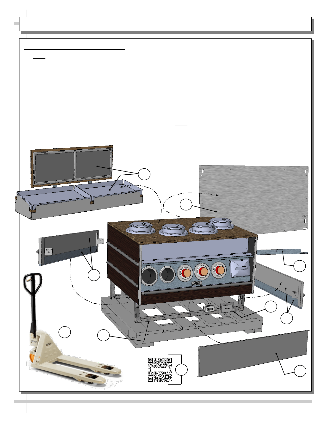
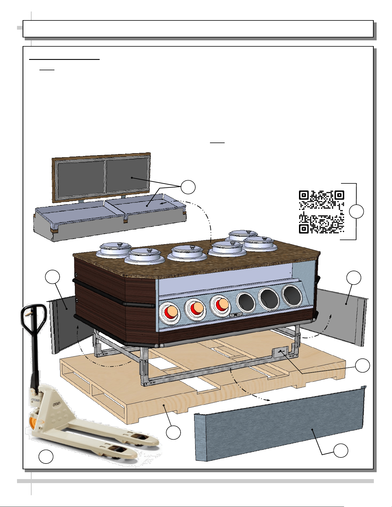
COMPONENT REMOVAL: IN-LINE CASES
Component Removal: In-Line Cases
>> Note: In-line model FB4SS-47QN.8098 (shown
below) may not reflect every feature or option of
your particular case. However, directions are still
applicable.
>> Before removing case from skid, you must
remove various components that could be
damaged. To do so, follow these instructions:
1. While case is on skid, move it to desired location
using pallet jack.
2. Remove signage assembly from atop case (by
lifting up and off).
4
5
7
7
3
Sample QR Code
8
6
5
2
1
3. Remove rear panel (after removing screws).
4. Remove front toe-kick (separating from magnets).
5. Remove LH and RH toe-kicks & close-offs (by
removing screws at front and rear of case).
6. Remove water guard bracket (after removing
screws).
7. Remove (4) screws from base rails that are
securing case to skid (2 at front and 2 at rear).
8. For Structural Concepts’ general overview, safety
precautions and limited warranty (as well as
registering your limited warranty), scan the QR
Code on the serial label behind the front toe-kick.
>> Note: Any revisions to these instructions must also
be made to SCC’s Component Removal &
Replacement Guide P/N 21-29440.
7
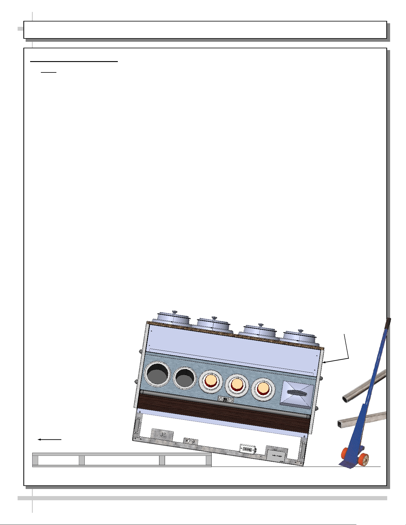
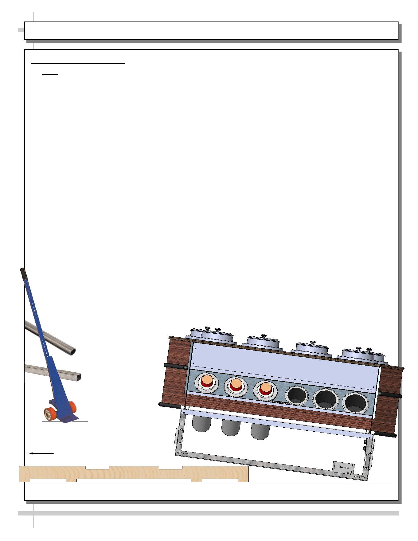
CASE REMOVAL FROM SKID: IN-LINE CASES
Case Removal From Skid
>> Note: In-line model shown (FB4SS-47QN.8098) may not reflect every feature or option of your particular
case. However, general directions are still applicable to your unit.
• Caution! Various components must removed from case before removing case from skid.
See previous page for specifics.
• To prevent damage, support case while sliding skid out from under case.
• Slide case to edge of skid.
• With several people in position, carefully slide frame support rail to edge of skid.
• Slide case several more inches (off skid) and lower rear frame support to floor.
• Once the rear frame support rail rests on the floor, have several people supporting front of case while
skid is slid out from under case.
• After case is off skid, several employees may be required to slide into position. Use pry bar, rigid tubes
or pallet jack (as needed) to accomplish this task.
Carefully Slide
Skid Out From
Under Unit
Support case while
removing from skid.
8
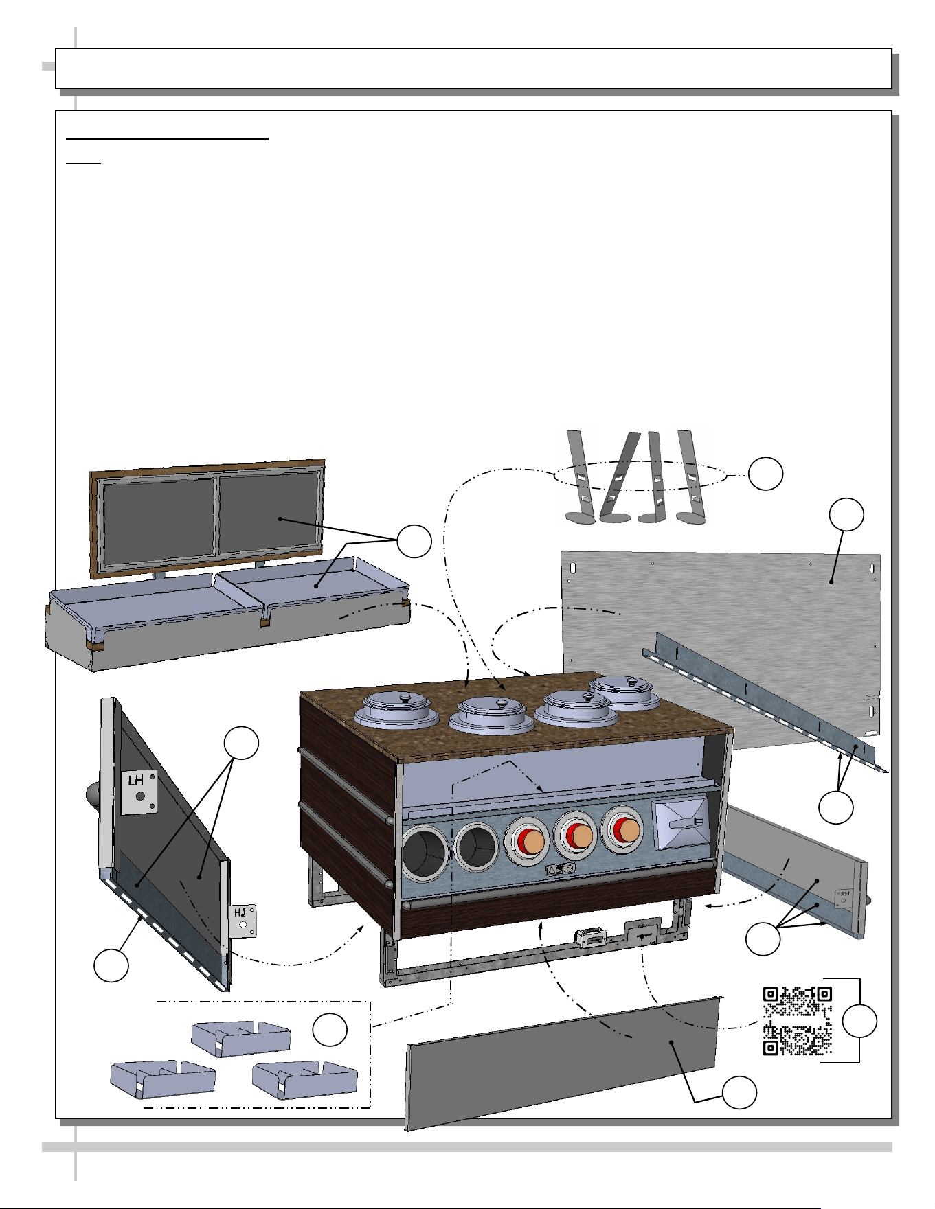
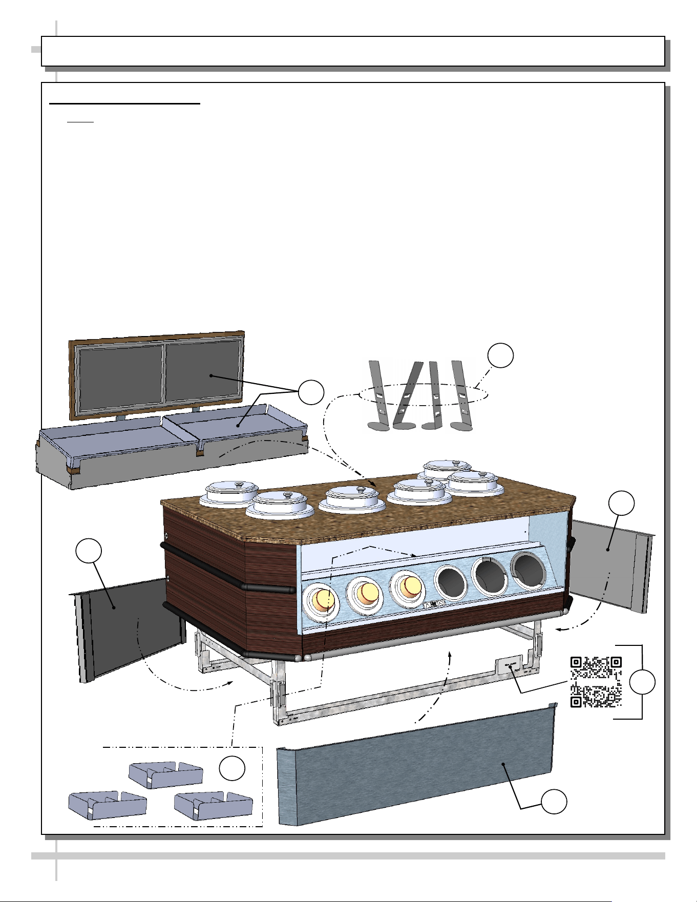
COMPONENT REPLACEMENT: IN-LINE CASES
Component Replacement
Note: Model FB4SS-47QN.8098 (shown below) may
not reflect every feature or option of your case.
>> After case has been removed from skid and
moved into place, you must replace various
components that may have been removed during
that process (or shipped separately). To do so,
follow these instructions:
1. Replace signage assembly atop case (no screw
attachment required).
2. Place sign holders behind soup wells.
3. Place (3) condiment containers (that had been
separately shipped) onto front shelf.
4. Replace LH and RH toe-kicks & close-offs (screw
in place at front and rear of case). Important!
Apply consistent bead of commercial grade
7
4
4
1
6
2
3
silicone sealant at underside of close-offs to
prevent entry of water to underside of case.
5. Replace water guard bracket at rear of case (via
screws). Important! Apply consistent bead of
commercial grade silicone sealant at underside
of water guard bracket to prevent entry of water
to underside of case.
6. Replace rear panel (via screws).
7. Replace front toe-kick (via magnets).
8. For Structural Concepts’ general overview, safety
precautions and limited warranty (as well as
registering your limited warranty), scan the QR
Code on the serial label behind the front toe-kick.
>> See next page for view of case after components
have been reattached.
Sample QR Code
8
5
4
9
VIEW OF CASE AFTER COMPONENT ATTACHMENT: IN-LINE CASES
View of Case After Components Attached: In-Line Cases
>> Note: Model FB4SS-47QN.8098 (shown below) has signage assembly, condiment containers, sign
holders, front and side toe-kicks, etc. attached.
>> Model shown below may not reflect every feature or option of your particular case.
Model FB4SS-47QN.8089 (Shown)
May Not Reflect Every Feature of
Your Particular Case.

10
COMPONENT REMOVAL AND REPLACEMENT SECTION FOR ISLAND / “END CAP” CASES
COMPONENT
REMOVAL
AND
REPLACEMENT
SECTION
FOR
ISLAND (AKA
“END CAP”)
CASES
11
COMPONENT REMOVAL: ISLAND (AKA “END CAP”) CASES
Component Removal
>> Note: Model FBI6SS-67QN.8099 (shown) may
not reflect every feature or option of your particular
case. However, directions are still applicable to your
island (AKA “end cap”) unit.
>> Before removing case from pallet, you must
remove various components that could be
damaged. To do so, follow these instructions:
1. While case is on pallet, move it to desired location
using pallet jack.
3
4
2
4
Sample QR Code
6
2. Remove signage assembly from atop case (by
lifting up and off).
3. Remove front toe-kick (separating from magnets).
4. Remove LH and RH toe-kicks (separating from
magnets).
5. Remove (4) screws from base rails that are
securing case to pallet (2 at front and 2 at rear).
6. For Structural Concepts’ general overview, safety
precautions and limited warranty (as well as
registering your limited warranty), scan the QR
Code on the serial label behind the front toe-kick.
>> Note: Any revisions to these instructions must also
be made to SCC’s Component Removal &
Replacement Guide P/N 21-29440.
5
1
6
12
CASE REMOVAL FROM PALLET: ISLAND (AKA “END CAP”) CASES
Case Removal From Pallet
>> Note: Model FBI6SS-67QN.8099 (shown) may not reflect every feature or option of your particular case.
However, directions are still applicable to your island (AKA “end cap”) unit.
• Caution! Various components must removed from case before removing case from pallet.
See previous page for specifics.
• To prevent damage, support case while sliding pallet out from under case.
• Slide case to edge of pallet.
• With several people in position, carefully slide frame support rail to edge of pallet.
• Slide case several more inches (off pallet) and lower rear frame support to floor.
• Once the rear frame support rail rests on the floor, have several people supporting front of case while
pallet is slid out from under case.
• After case is off pallet, several employees may be required to slide into position. Use pry bar, rigid tubes
or pallet jack (as needed) to accomplish this task.
Carefully Slide Pallet
Out From Under Unit
13
COMPONENT REPLACEMENT: ISLAND (AKA “END CAP”) CASES
Component Replacement
>> Note: Model FBI6SS-67QN.8099 (shown) may
not reflect every feature or option of your particular
case. However, directions are still applicable to your
island (AKA “end cap”) unit.
>> After case has been removed from skid and
moved into place, you must replace various
components that may have been removed during
that process (or shipped separately). To do so,
follow these instructions:
1. Replace signage assembly atop case (no screw
attachment required).
2. Place sign holders behind soup wells.
1
2
3
3. Place (3) condiment containers (that had been
separately shipped) onto front shelf.
4. Replace LH and RH toe-kick (reattaching via
magnets).
5. Replace front toe-kick (via magnets).
6. For Structural Concepts’ general overview, safety
precautions and limited warranty (as well as
registering your limited warranty), scan the QR
Code on the serial label behind the front toe-kick.
>> See next page for view of case after components
have been reattached.
5
4
4
Sample QR Code
6
14
VIEW OF CASE AFTER COMPONENT ATTACHMENT: ISLAND (AKA “END CAP”) CASES
View of Island (AKA “End Cap” Case) After Component Attachment
>> Note: Model FBI6SS-67QN.8099 (shown) may not reflect every feature or option of your particular case.
However, directions are still applicable to your island (AKA “end cap”) unit.
15
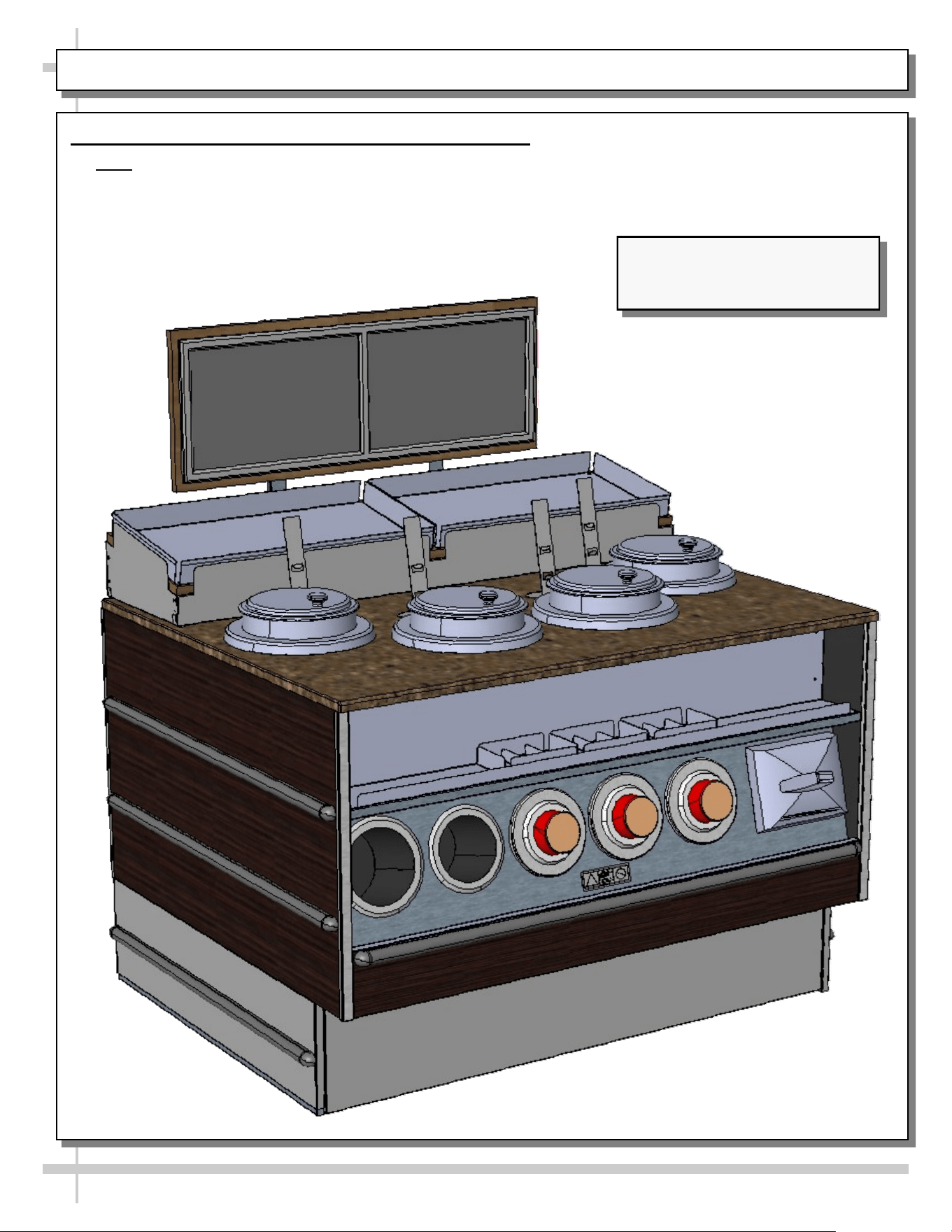
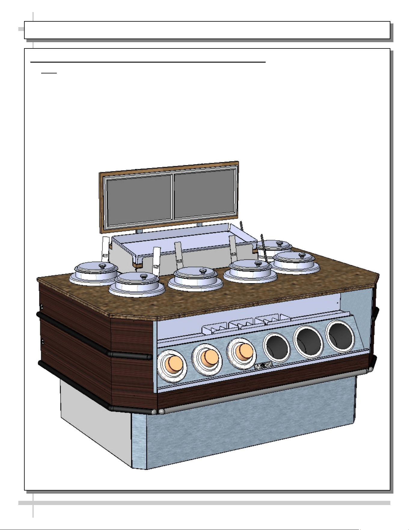
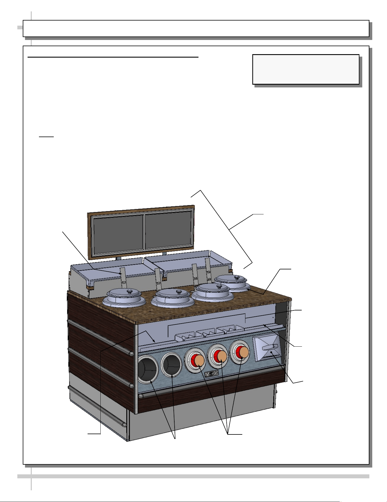
1. General Layout - Soup Utensil / Napkin / Supplies
Illustration below shows the various components to
these merchandisers.
• Soup signage bar
• Rethermalizing soup induction warmers
• Sign card holders
• Condiment containers
• Lid dispensers (large and small)
• Bowl dispensers
• Napkin dispensers
• Note: Though your model may differ from the one
shown, general layout of temperature controller to
heated well will apply.
Small and Large
Lid Dispensers
Bowl Dispensers: See
DISPENSE-RITE CUP
DISPENSER ADJUSTMENT
INSTRUCTIONS section in
this User Manual.
Sign Card
Holder (Typ.)
Soup Signage Bar (See SOUP
SIGNAGE BAR SYSTEM
PIECES Section in This Manual
for Individual Piece Breakdown)
GENERAL LAYOUT - SOUP SIGNAGE BAR / DISPENSERS / SOUP WARMERS / CONTAINERS
Napkin
Dispenser
Model FB4SS-47QN.8089 (Shown)
May Not Reflect Every Feature of
Your Particular Case.
7 qt. Vollrath®
Rethermalizing
Soup Induction
Warmer (Typ.)
Condiment
Containers
(Crackers, Etc.)
Ledge For Other
Condiments (Buns,
Crackers, Etc.)
Ledge For Other
Condiments (Buns,
Crackers, Etc.)

16
GENERAL LAYOUT, CONT’D - SOUP SIGNAGE BAR SYSTEM PIECES
4. Place baskets
into position
1. Sign and sign
rails may be shipped
as one piece.
3. Sign rails to be
attached to rear of
base support.
5. Place utensil bins into
unit at center of case.
2. Place purchased
frame onto sign
Baskets For Pan Condiments,
Bread, Crackers, Etc.
Base Support
Sign and
Frame
Model FB4SS-47QN.8089 (Shown)
May Not Reflect Every Feature of
Your Particular Case.
Base Support
2. General Layout - Soup Signage Bar System Pieces
Illustration below shows the various components to these
merchandisers.
• Soup signage bar components shown.
• Your unit’s components may slightly differ than those shown.
17
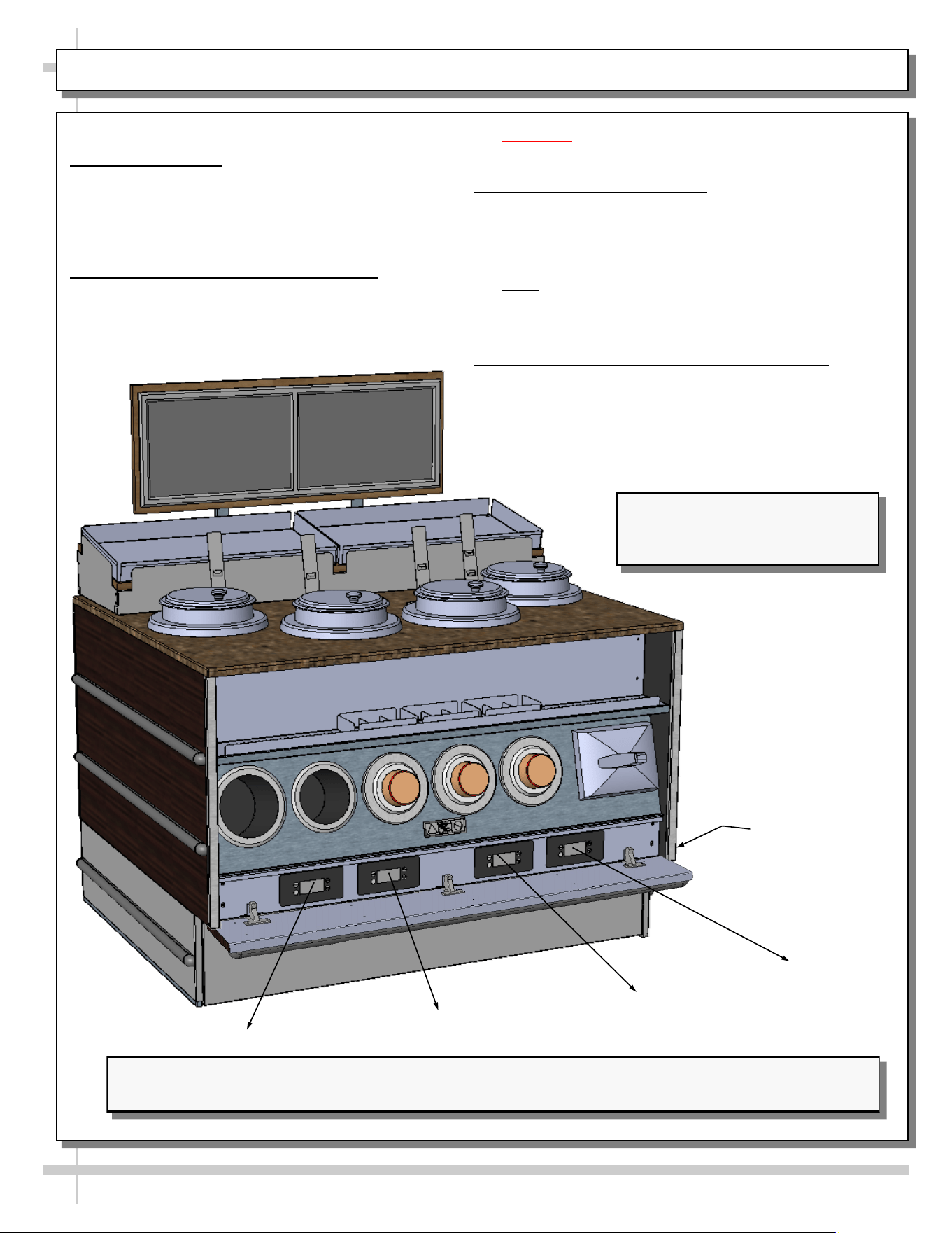
GENERAL LAYOUT, CONT’D - ENERGIZING CASE / WELLS ON & OFF SWITCH / THERMOSTATS
General Layout, Cont’d
3. Energizing Case
• Case will energize when properly plugged in
(or field-wired, depending upon design).
• Illustration below has front flip-up cover raised
to show access to control panel.
4. Heated Wells On/Off Switch Control
• Each heated well has its own On/Off Switch
(see illustration below).
• Caution! Heated Wells can get very hot! Use
extreme caution!
5. Heated Wells Thermostats
• Each heated well temperature plate controls a
different heated well.
• See illustration below for specifics on which control
dial controls each heated well.
• Note: Though your model may differ from the one
shown, general layout of temperature controller to
heated well will apply.
6. Daily Step-By-Step Soup Well Operations
• See VOLLRATH® INDUCTION WARMERS -
CONTROL PANEL / HOT FOOD HOLDING /
SETTING TEMPERATURE section in this
operating manual for step-by-step operational
procedures.
Important! See VOLLRATH® INDUCTION WARMERS - CONTROL PANEL / HOT FOOD HOLDING /
SETTING TEMPERATURE section in manual for specifics on controlling soup well temperatures.
Flip-Down Cover
Model FB4SS-47QN.8089 (Shown)
May Not Reflect Every Feature of
Your Particular Case.
1
2
3
4
4
3
2
1
18
GENERAL LAYOUT, CONT’D - FIELD ACCESS BOX / ELECTRICAL OUTLETS / PACEMAKER WARNING
7. Field Access Box (To Be Routed To Outlet)
• A 2 x 4 field access box is at lower front of case
behind front toe-kick (as shown below).
• Two (2) 4 x 4 electrical outlets (for soup well
plugs) are behind upper front panel.
• Warning to pacemaker wearers is prominently
displayed at center of case.
Upper Front Panel
Front Toe-Kick
Model FB6SS-67QN.8089 (Shown)
May Not Reflect Every Feature of
Your Particular Case.
GENERAL LAYOUT, CONT’D - DISPENSE-RITE CUP DISPENSER ADJUSTMENT INSTRUCTIONS
19
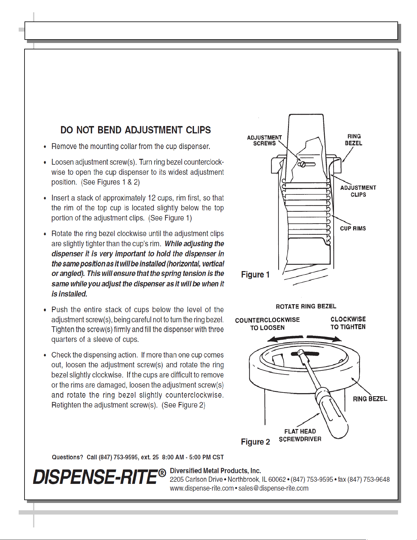
DISPENSE-RITE® ADJ-1, ADJ-2 & ADJ-3 SERIES
ADJUSTMENT INSTRUCTIONS
FOLLOW THESE INSTRUCTIONS
20
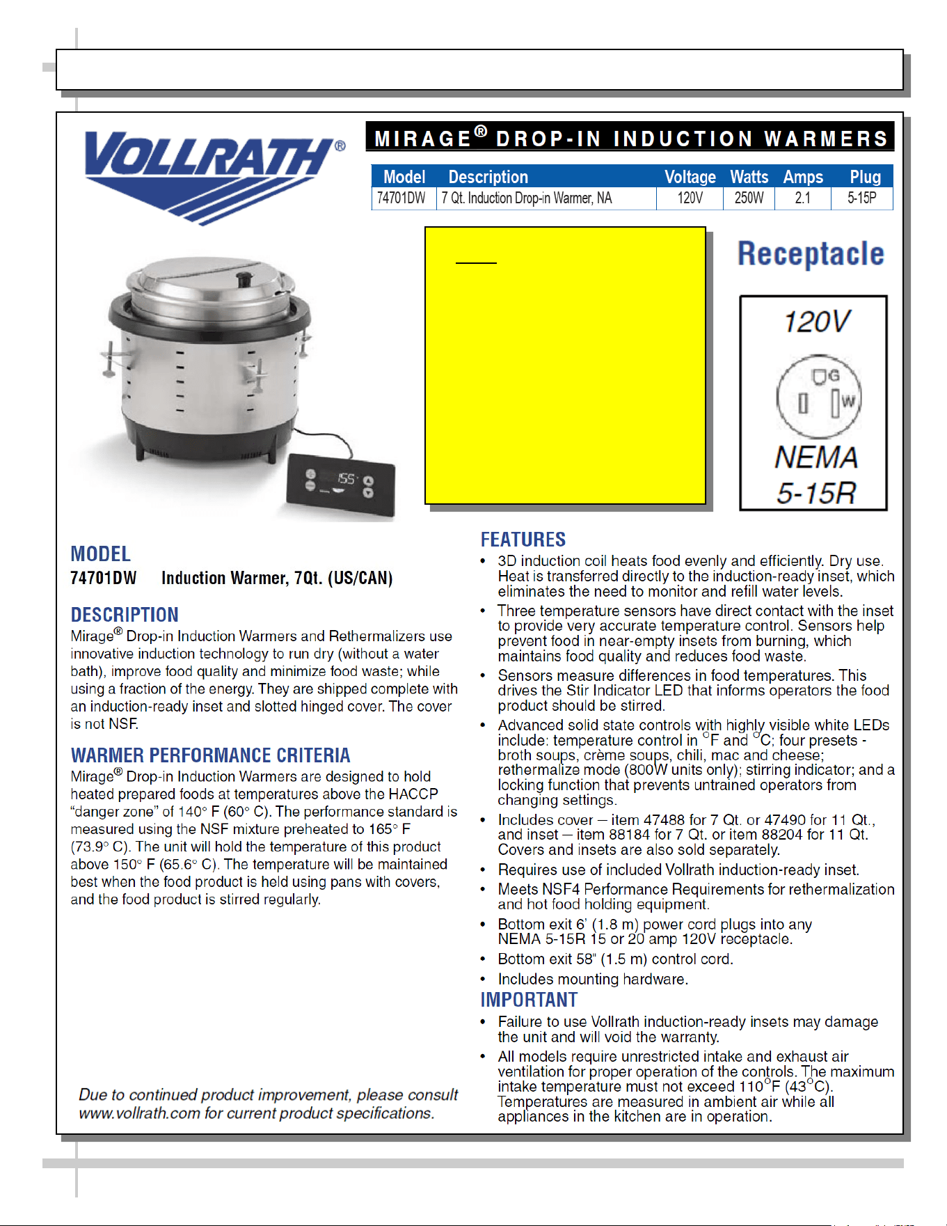
VOLLRATH® INDUCTION WARMERS - MODEL / SPECS / DESCRIPTION / CRITERIA / FEATURES
Note: The information on
these sheets is based on
Vollrath’s specifications and
Operator’s Manual.
For additional information,
consult Vollrath’s full
Operator’s Manual and/or
www.Vollrath.com for current
product specifications.
21
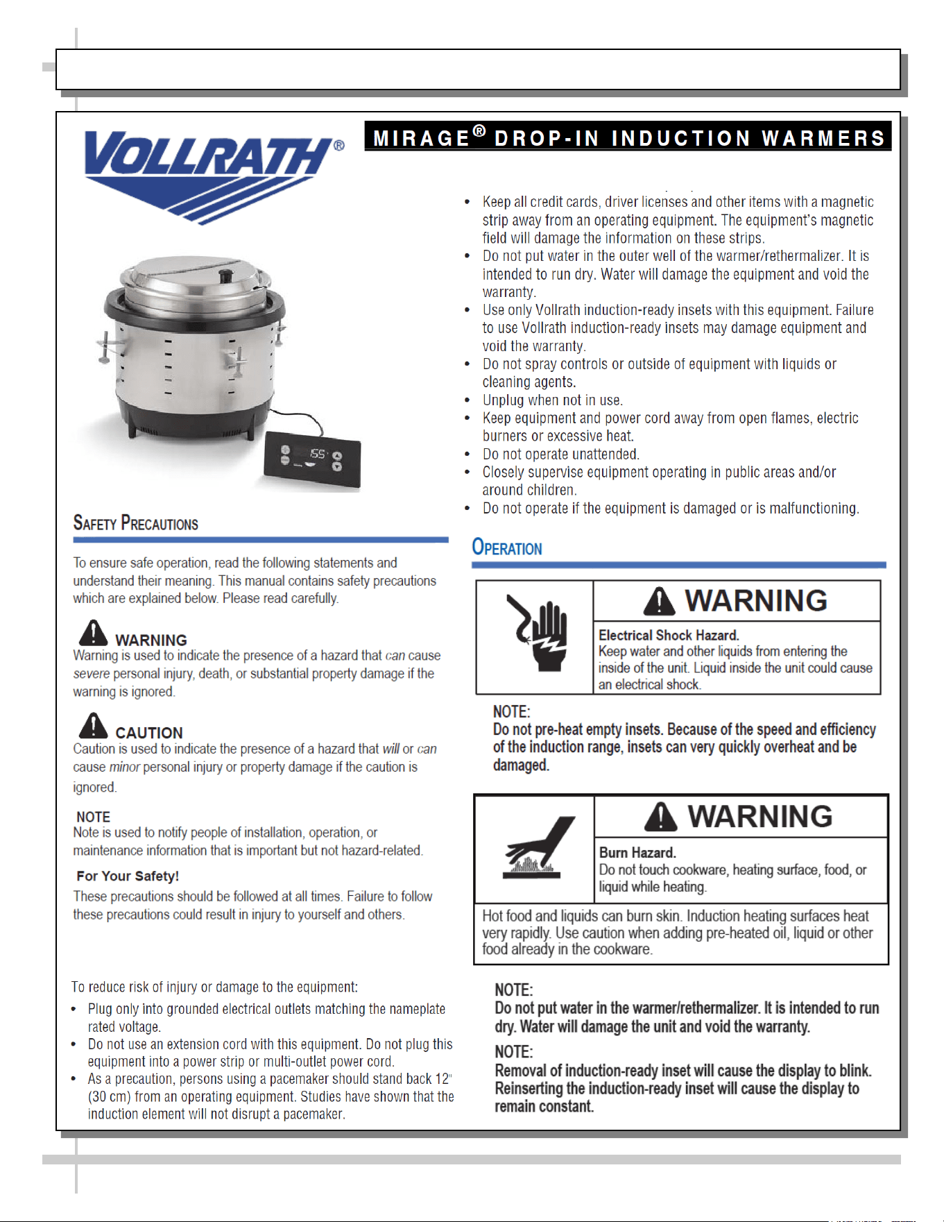
VOLLRATH® INDUCTION WARMERS - SAFETY PRECAUTIONS / OPERATION / WARNINGS
To reduce risk of injury or damage to the unit, continued:
NOTICE: Notice is used to note information that is important but not
hazard-related.
22
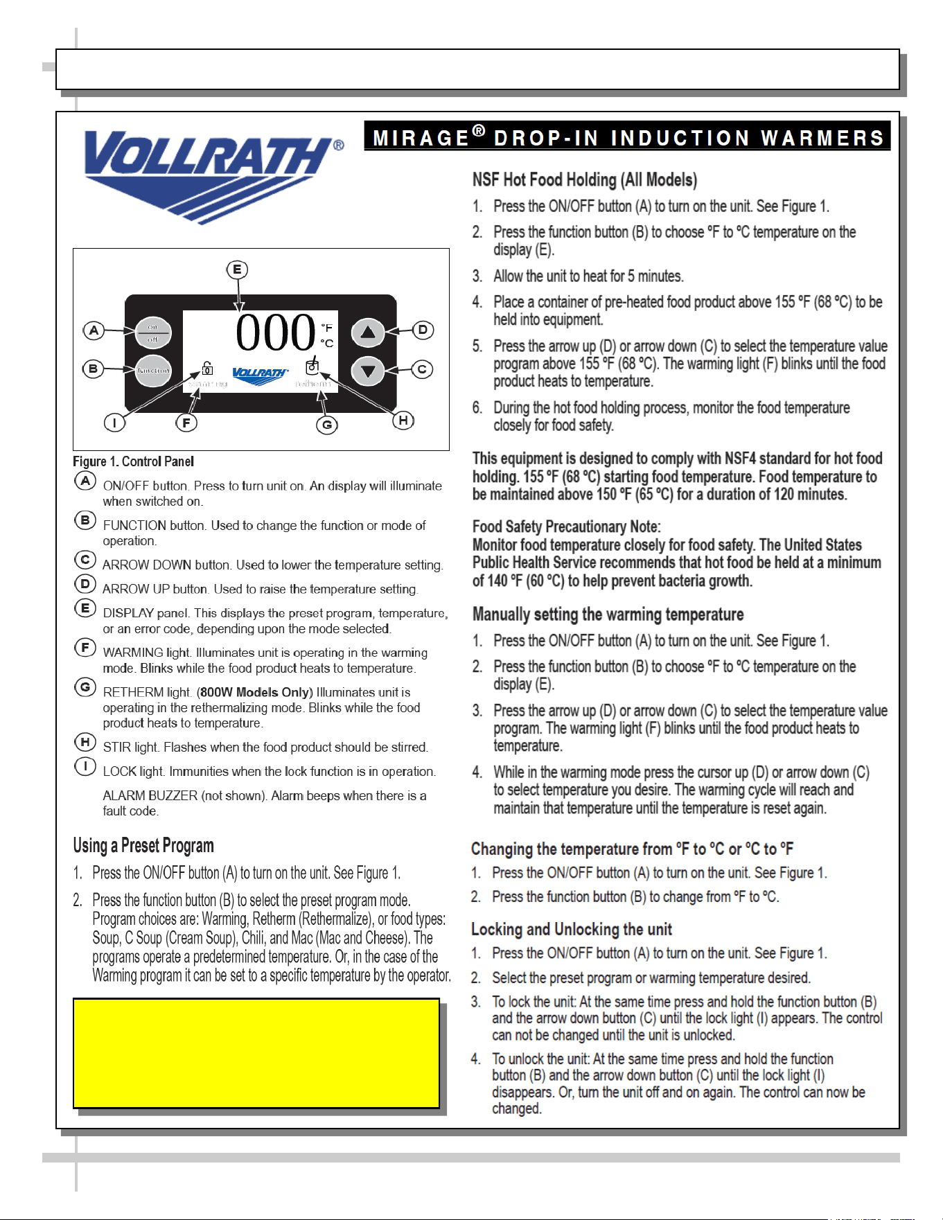
VOLLRATH® INDUCTION WARMERS - CONTROL PANEL / HOT FOOD HOLDING / SETTING TEMP.
FOOD Safety Precautionary Note:
Monitor food temperature closely for food safety.
The United States Public Health Service recommends
that hot food be held at a minimum of 140 °F (60 °C)
to help prevent bacterial growth.
23
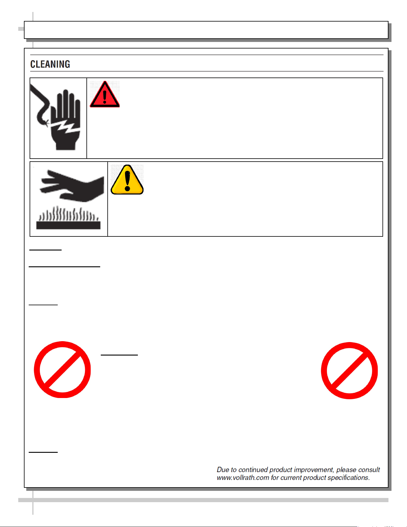
VOLLRATH® INDUCTION WARMERS - CLEANING
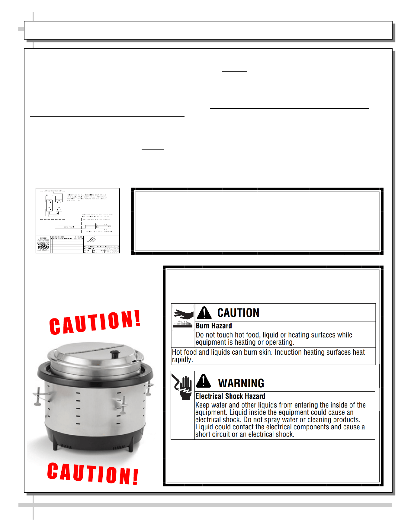
> Keep water and other liquids from entering the inside of the equipment.
> Liquid inside the equipment could cause an electrical shock.
> Do not spray water or cleaning products.
> Liquid could contact electrical components & cause a short circuit or an electrical shock.
WARNING: Electrical Shock Hazard
CAUTION: Burn Hazard
> Hot surfaces and food can burn skin.
> Allow the hot surfaces to cool before handling.
> Do not drop or spill water onto the cooking surface as it can spray or splatter.
Important: To maintain the appearance and increase the service life, clean this equipment daily.
What you will need:
• Three soft clean cloths, one each for cleaning, rinsing and drying.
• Mild dish washing detergent • Clean warm water
NOTICE: Failure to follow these cleaning instructions may lead to product damage that will not
be covered under warranty.
1. Unplug the equipment and let it completely cool.
2. Use a soft cloth moistened with warm water & mild dish washing detergent to clean the well and rim.
NOTICE: DO NOT use cleaning solutions that
contain chlorine or bleach ingredients.
Use of solutions with these ingredients will
damage the well and will void the warranty.
3. Use the second clean soft clean soft cloth moistened with clean warm water to wipe all detergent
from the well and the rim.
4. Use the third soft clean cloth to dry the well and the rim.
NOTICE: Failure to thoroughly remove all detergent or thoroughly dry the equipment may
result in damage to the equipment.
5. The stainless steel insert is dishwasher safe.
CHLORINE
BLEACH
24
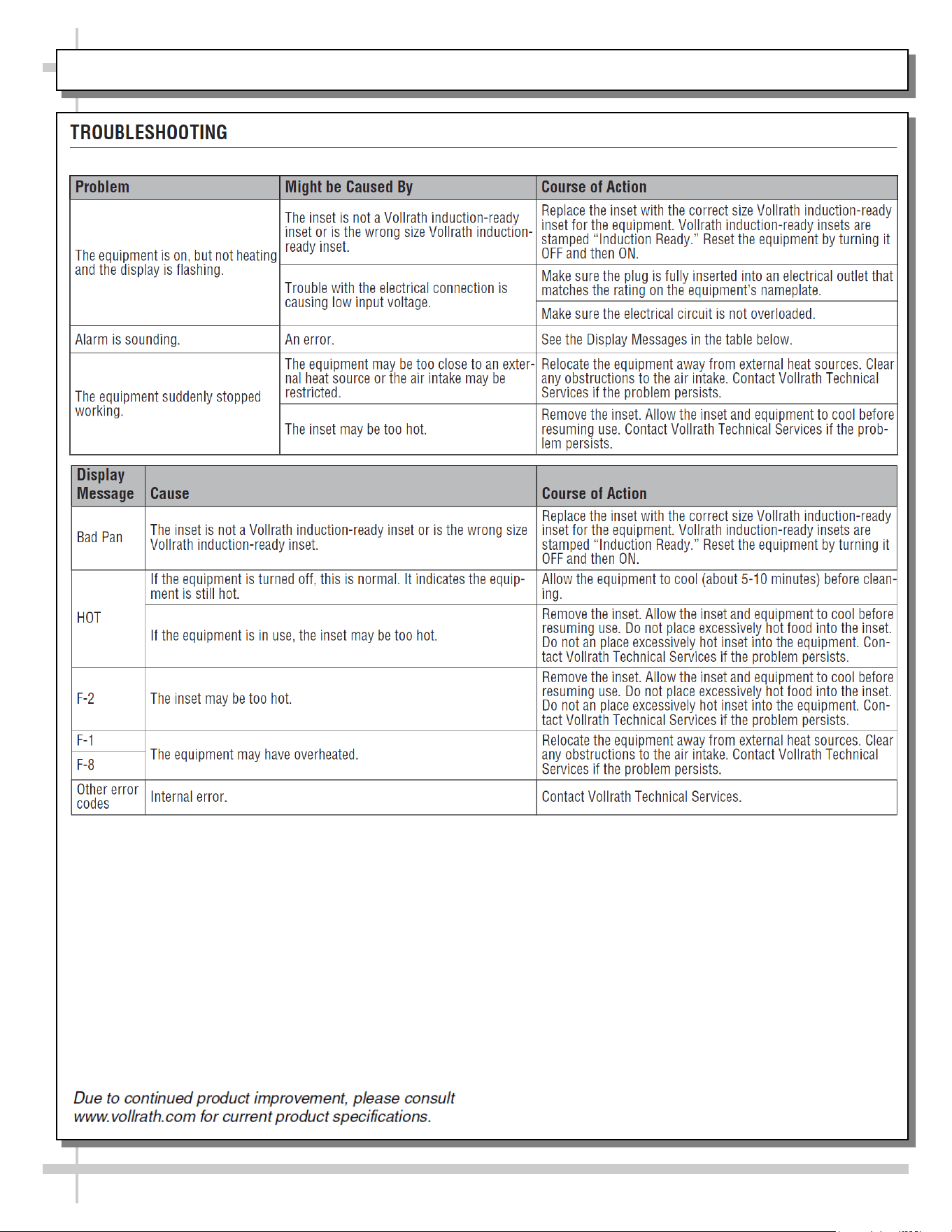
VOLLRATH® INDUCTION WARMERS - TROUBLESHOOTING
25
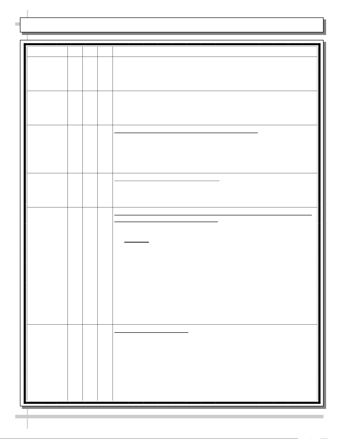
CLEANING SCHEDULE - GENERAL (DAILY “D” / WEEKLY “W” / MONTHLY “M”)
Cleaning D W M Task
Clean Case
Exterior
X Clean wood, laminate and painted surfaces with a warm soap and water
solution and soft cloth. Never use wire cloth or abrasive cleaners on case.
X SOLID SURFACE (Countertop): See next page for cleaning and
maintenance instructions.
X Optional sign holders (behind each heated soup well): Wipe down with a
warm soap and water solution and soft cloth. Never use wire cloth or
abrasive cleaners on sign holders.
Clean Case
Interior
X Vollrath® Inductive Heated Soup Wells: See VOLLRATH® INDUCTION
WARMERS - CLEANING section in this manual.
X Stainless steel utensil dispensers and surfaces (napkin dispenser, bowl &
lid dispensers, spoon dispensers, etc.):
• Remove all supplies. Wipe down areas with warm soap and water
solution and soft cloth.
• Caution! Never use abrasive material such as steel wool or ‘Brillo®
Pads’ to clean stainless steel areas. Do not use abrasive cleaners with
gritty or harsh chemicals to clean stainless steel areas as these can
scratch the finish, dulling and marring its appearance.
X Trash bins / storage drawer: Slide out from under case. Wipe down with
clean, soft cloth dipped in warm soapy water. Dry. Slide back under case.
26
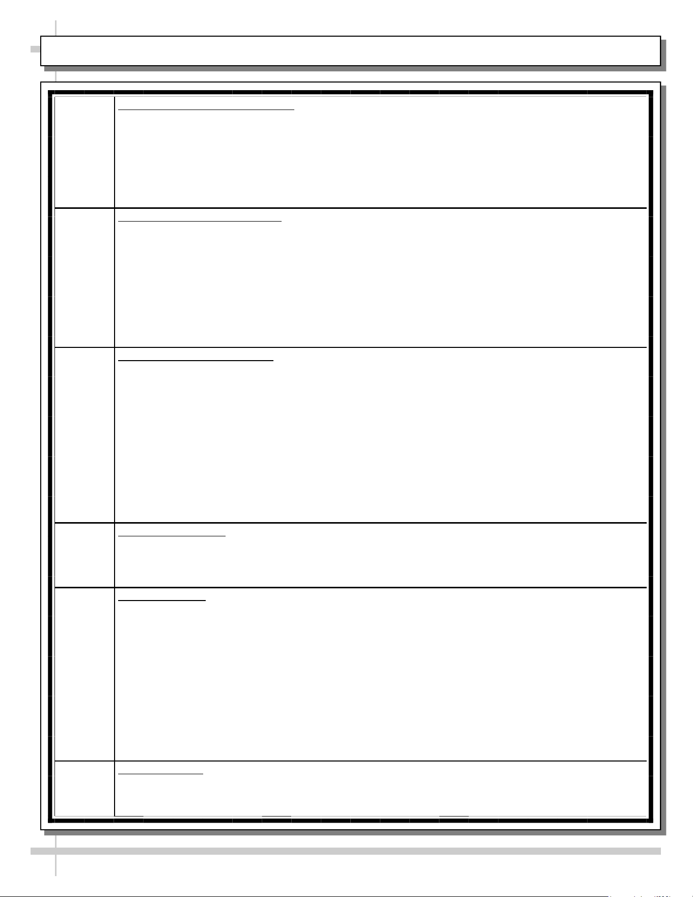
ENGINEERED (SYNTHETIC) QUARTZ CARE AND MAINTENANCE
Engineered
Quartz
Overview
Engineered (Synthetic) Quartz Overview:
• Engineered (synthetic) quartz is a ‘man-made’ product. It is sometimes called “engineered stone.” It is made from
crushed quartz particles bonded with polyester, styrene, resin, pigments and tert-butyl peroxybenzoate.
• It is non-porous, mold and mildew-resistant, and impervious to odor-causing bacteria.
• Slabs are specifically sized. Engineered quartz contains a maximum of 94% mineral quartz (though percentages
vary). Engineered quartz is extremely resistant to damaging chemicals.
• There are many engineered (synthetic) quartz brands. These include Caesarstone, Cambria, Compac, Corian, Daltile
ONE, Granite HanStone, Transformations, Kowalski, LG Hausys, LG Viatera, Lunastone, Marble.com, MSI Q, Okite,
Pental, Polarstone, Pompeii, Samsung, Sensa, Silestone, Stone Italiana, Vadara, Vena & Vicostone.
Routine
Care
For Daily, Routine Care and Cleaning:
Engineered (synthetic) quartz require very little maintenance. Simply wipe the surface with neutral pH balanced
household detergent and warm water solution with soft sponge or microfiber cloth to maintain its shine.
• To prevent fading, keep from harsh, direct sunlight for long periods of time.
• General cleaners: use neutral pH balanced household detergent and warm water (4 cups of water/1 teaspoon of
detergent). Or isopropyl alcohol (aka rubbing alcohol). Or use any general, all-purpose cleaner, glass cleaner or Pine
Sol. Or use Clorox Wet Wipes (as they contain no bleach or and are soft). After cleaning, thoroughly rinse with water
and dry with clean cloth to prevent water spots from forming.
• Specifically designed cleaners for manufactured quartz: Black Diamond Stoneworks Granite Counter Cleaner,
Caldrea Countertop Spray, Clark’s Natural Stone Spray Cleaner, Granite Gold, Simple Green, Park & Bailey Granite
& Stone Cleaner, Seventh Generation Granite & Stone Cleaner, Stone Care Quartz Clean & Shine, Stone Pro Quartz
Countertop Cleaner, Weiman Quartz Countertop Cleaner and Polish.
Difficult
Spills
For Difficult Spills, Stains and Spots:
• Thoroughly clean with warm water and neutral pH detergent (mixture detailed above) before pursuing next steps.
• Clean up high staining liquids such as coffee, tea, fruit juice, lemon juice, vinegar, wine and tomato juice right away.
Use warm water and neutral pH detergent to do so. After cleaning, thoroughly rinse with water and dry.
• For residues that harden as they dry (food, gum, nail polish, and paint), place wet cloth or paper towel over residue
for 10 minutes (to soften its properties); then gently scrape off residue by using a plastic putty knife or plastic scraper;
avoid metal blades or scrapers if possible; then clean using warm water and soap. If you must use metal razor blade
or scraper, remove gray marks with soap and water. Thoroughly rinse with water and dry to prevent water spots.
• Difficult spots may need to be treated with solutions/chemicals BEYOND warm water and neutral pH detergents: A.
Water/white vinegar mixture: 2 cups of water with 1 tablespoon of white vinegar in spray bottle; spray surface; allow
solution to sit for 2 minutes; wipe off with soft cloth or sponge. B. Soft Scrub Liquid Gel: Apply gel to cloth or sponge
(not directly to quartz surface); wipe the area in a circular motion; repeat until spot is removed. C. Goo Gone
adhesive remover (for sticky residue). Thoroughly rinse the surface with water and wipe dry to prevent water spots.
• Water stain removal: 1 part vinegar + 3 parts baking soda in warm water. Dip cloth in mixture and thoroughly soak
stain. Leave for 5-10 minutes; then scrub area with soft brush. Rinse with water and dry with clean cloth.
Extreme
Heat
Protection
Extreme Heat Protection:
• Engineered quartz is extremely resistant to heat, and can withstand moderately high temperatures for brief periods of
time without being damaged.
• Engineered quartz CAN BE damaged by sudden and extreme temperature changes; thus, use a trivet or a hot pad to
protect its surface from hot pans, hot dishes or small appliances that may reach high temperatures.
Chemicals
To
Avoid
Chemicals To Avoid:
• Nail polish remover (acetone), oil soaps, and furniture cleaners or paint strippers that contain trichloroethane or
methylene chloride.
• Chemicals with an alkaline level of pH >10 (oven cleaners, chloring bleach, lacquer thinner, ammonia, tub and tile
cleaner, borax, etc.)
• Chlorinated solvents (trichloroethylene or methylene chloride)
• Concentrated acids (hydrocyanic acid, hydrofluoric acid, hydrochloric acid, sulfuric acid, nitric acid or CLR)
Caution must be used for the following products on engineered quartz surfaces:
• Avoid using products containing oils or powders as may leave a residue.
• Avoid abrasive scrubs/cleaners (such as Ajax, Comet, Scotch-Brite or oven cleaner) as it dull or discolor the finish.
Common stains like coffee, food, makeup, permanent markers, etc.:
• Apply the appropriate cleaner with a paper towel and wipe. If necessary, soak with paper towels from 3-10 minutes.
• Scrub the area with a non-abrasive cloth or sponge. Rinse and dry thoroughly.
Preventing
Scratches
Scratch Deterrence: Engineered quartz surfaces are scratch RESISTANT. However, they CAN be scratched or marred
by certain utensils or cleaning materials.
• Use a cutting board to avoid damaging the quartz surface and knives.
• Never use abrasive scouring pads, steel wool soap pads, Brillo® pads or “Magic Erasers.
27
TROUBLESHOOTING - GENERAL CASE ISSUES (FOR TRAINED SERVICE PERSONNEL ONLY)
CONDITION TROUBLESHOOTING - GENERAL CASE ISSUES
System Is Not
Operating
Check that the utility power is on.
Check that the field access box is properly wired.
Check that the temperature control dial is turned up.
Check the circuit breaker box for tripped circuits.
Induction soup well issues: See VOLLRATH® INDUCTION WARMERS -
CLEANING / TROUBLESHOOTING section in manual for specifics.
28
SERIAL LABEL LOCATION & INFO LISTED / TECH INFO & SERVICE - AMBIENT/HEATED CASES ONLY
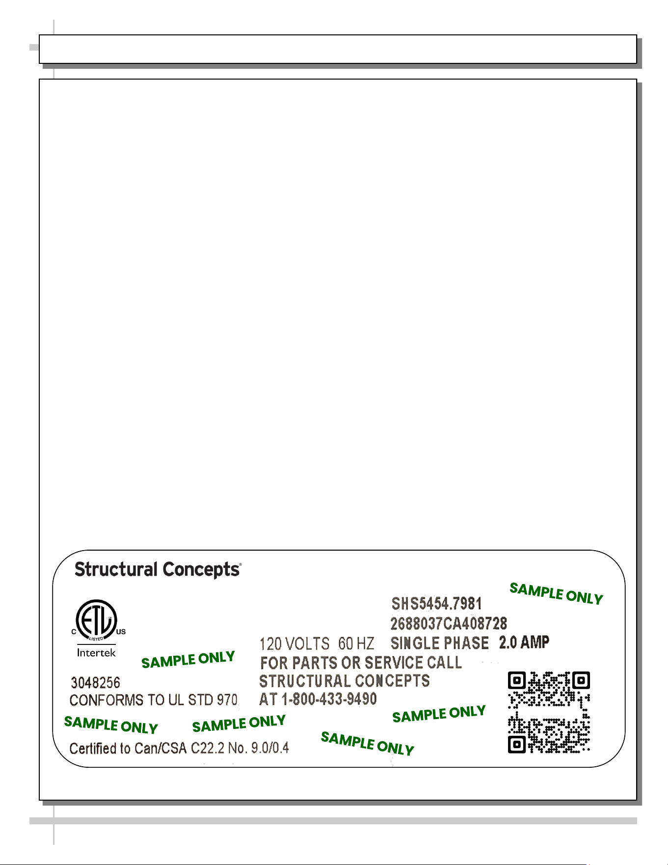
Serial Label Location & Information Listed /
Technical Information & Service
• Serial labels are affixed at a wide range of places
(on the header, at case rear, behind panels or
toe-kicks, on electrical boxes, etc.).
• Serial labels contain electrical information as well
as regulatory standards to which the case
conforms.
• Sample serial label is shown. A variety of models is
displayed on serial label for illustration purposes only.
Your case’s serial label will reflect only one model.
• For additional technical information and service, see
the TECHNICAL SERVICE page in this manual for
instructions on contacting Structural Concepts’
Technical Service Department.
--- Sample Serial Label For Ambient/Heated Cases ---
888 E. Porter Rd - Muskegon, MI 49441
Sample QR Code
SCAN FOR PRODUCT LITERATURE
Reveal
Harmony
Impulse
Addenda
STRUCTURAL CONCEPTS TECHNICAL SERVICE CONTACT INFORMATION & LIMITED WARRANTY
29
TECH SERVICE/WARRANTY CONTACT INFO:
1 (800) 433-9490 / EXTENSION 1
DAYS/HOURS AVAILABLE:
MONDAY - FRIDAY (CLOSED HOLIDAYS)
8:00 AM to 8:00 PM EST
YOU MUST HAVE THE FOLLOWING INFO AVAILABLE
BEFORE CONTACTING STRUCTURAL CONCEPTS:
SERIAL NO. / MODEL NO. / STORE NO. / STORE
ADDRESS / DETAILS (PHOTOS, LEAK LOCATIONS,
DAMAGE, STORE’S AMBIENT CONDITIONS, ETC.)
To Access The Limited Warranty To Your
Case, Follow These Instructions:
> If Viewing This Document on Smart Phone,
Tablet or Computer, Select/Click On The QR
Code at Right.
> If Viewing This Document In Print (Hard
Copy), Scan The QR Code at Right With Your
Smart Phone or Tablet.
