

GROCERANT™ REMOTE SELF-SERVICE INLINE COLD WELL FOOD MERCHANDISERS WITH
DROP-IN PANS ||| NOTE: UNITS MAY INCLUDE CERTAIN FEATURES OR OPTIONS LISTED BELOW:
REV D DATE: 12/20/2022
USER MANUALS\20-96491_GROCERANT_USER MANUAL_FB(L)SS-(L)R_REF_RMT_SELF-SVC_CANOPY_FOOD PREP V2 CASE
Models Shown on This Cover May Not Reflect
Every Feature Or Option of Your Particular Case
Nor Other Models Illustrated In This Manual.
> ADJUSTABLE SNEEZE GUARD GLASS DESIGN
> STAINLESS STEEL SUPPORT POSTS
> REFRIGERATED INSULATED WELLS
> REFRIGERATED WELLS WITH “SHARED AIR” PLENUMS
(SEE “SHARED AIR” SECTION IN MANUAL FOR
SPECIFICS)
> REAR REFRIGERATED STORAGE VIA SLIDING DOORS,
HINGED DOOR OR DRAWERS
> OPTIONAL OPEN/AMBIENT REAR STORAGE
> ADJUSTABLE SIDE SPLASH BRACKETS
> REMOVABLE FRONT PANEL (FOR ADJOINMENT
PURPOSES)
> GUSSETS AND TABS (FOR ADJOINMENT PURPOSES)
> REMOVABLE REAR PLATE (FOR ADJOINMENT PURPOSES)
Model FB8SS-6R
Shown With
Drop-In Pans
Model FB6SS-4R
With Cubby
SCC P/N
20-96491
USER
MANUAL
GROCERANT
CAREFULLY FOLLOW THESE INSTRUCTIONS
Structural Concepts Corp. ∙ 888 E. Porter Rd ∙ Muskegon, MI 49441 Phone: 231.798.8888 Fax: 231.798.4960 ∙ www.structuralconcepts.com

2
TABLE OF CONTENTS
TABLE OF CONTENTS …...………………………………………………………………………….………...
OVERVIEW / CONDITION “TYPE” / COMPLIANCE / WARNINGS / PRECAUTIONS .…....................
CASE REMOVAL FROM SKID / POSITIONING / FORK LIFT / J-BAR or DOLLY .…..……..….…..….
ADJOINMENT GUIDE: LOWERING FRONT PANEL FOR END PANEL ADJOINMENT .....……..…....
ADJOINMENT GUIDE, CONT’D: REAR ADJOINMENT ACCESS (VIA COVER PLATE REMOVAL)..
ADJOINMENT GUIDE, CONT’D: BASE FRAME / GUSSET / BREAKOFF ADJOINMENT BRACKET
SPLASH GUARD BRACKETS: INSERTION AT CASE FRONT / ADJUSTABILITY / SEALING TO
FLOOR ……………………………………………………………………………………………………
FRAME SUPPORT RAILS / REMOVABLE FRONT AND REAR TOE-KICKS …………………………..
ELECTRICAL OVERVIEW: FIELD ACCESS / DRIVERS / FIELD SENSOR / T-STRIP …..……...........
ELECTRICAL OVERVIEW, CONT’D: THERMOMETERS ………………………………………………….
START-UP & OPERATION - REFRIGERATED UPPER SECTION …..…………………………………...
REFRIGERATED REAR SECTION WITH SLIDING DOORS ………………………………………………
REFRIGERATED REAR SECTION WITH DRAWERS ……………………………………………….……..
REFRIGERATED REAR SECTION WITH HINGED DOOR …………………………………………….…..
REAR REFRIGERATED “SHARED AIR” SECTION / SLIDING DOORS / THERMOMETERS ………..
CLEANING SCHEDULE: DAILY “D” / WEEKLY “W”....…………………………………………………...
CLEANING & MAINTENANCE of NATURAL QUARTZ SURFACES …..………………………………...
CLEANING SCHEDULE: CAESARSTONE® SOLID SURFACE ………………………………………….
CLEANING SCHEDULE: GRANITE, MARBLE & STONE SURFACE CLEANING, CARE &
MAINTENANCE ….……………………………………………………………………………………...
CLEANING SCHEDULE: STAINLESS STEEL ……………………………………………………………….
CLEANING SCHEDULE: DAILY / WEEKLY: DECK PANS / DIVIDERS / PRODUCT PANS / TUB .....
TROUBLESHOOTING (TO BE PERFORMED BY STORE PERSONNEL) ……………………………...
TROUBLESHOOTING (TO BE PERFORMED BY TRAINED SERVICE PROVIDERS ONLY) ………..
SERIAL LABEL LOCATION & INFORMATION LISTED / TECH INFO & SERVICE …………………...
TECHNICAL SERVICE CONTACT INFORMATION / WARRANTY INFORMATION …………………...
2
3-4
5
6
7
8
9
10
11
12
13
14
15
16
17
18
19
20
21
22
23
24
25
26
27
3
OVERVIEW
• These Structural Concepts cases are designed to
merchandise packaged products at 41 °F (5 °C) or less
product temperatures (unless custom cases with wire
rack shelving).
• Product must be pre-chilled to 41 °F (5 °C) or less before
being placed in merchandiser.
• Cases should be installed and operated according to this
operating manual’s instructions to ensure proper
performance. Improper use will void warranty.
TYPE 1 vs. TYPE 2 CONDITIONS
This unit is designed for the display of products in ambient
store conditions where temperatures and humidity are
maintained within a specific range.
• Type 1 conditions: ambient conditions are to be 55%
max. humidity and 75 °F (24 °C) max. temperature.
• Type 2 conditions: ambient conditions are to be 60%
max. humidity and 80 °F (27 °C) max. temperature.
• If unsure if unit is Type 1 or 2, see tag next to serial label.
See SERIAL LABEL LOCATION & INFORMATION
LISTED / TECH INFO & SERVICE section in this manual
for sample serial labels).
COMPLIANCE
• Performance issues when in violation of applicable
NEC, federal, state and local electrical and plumbing
codes are not covered by warranty.
• See below compliance guideline.
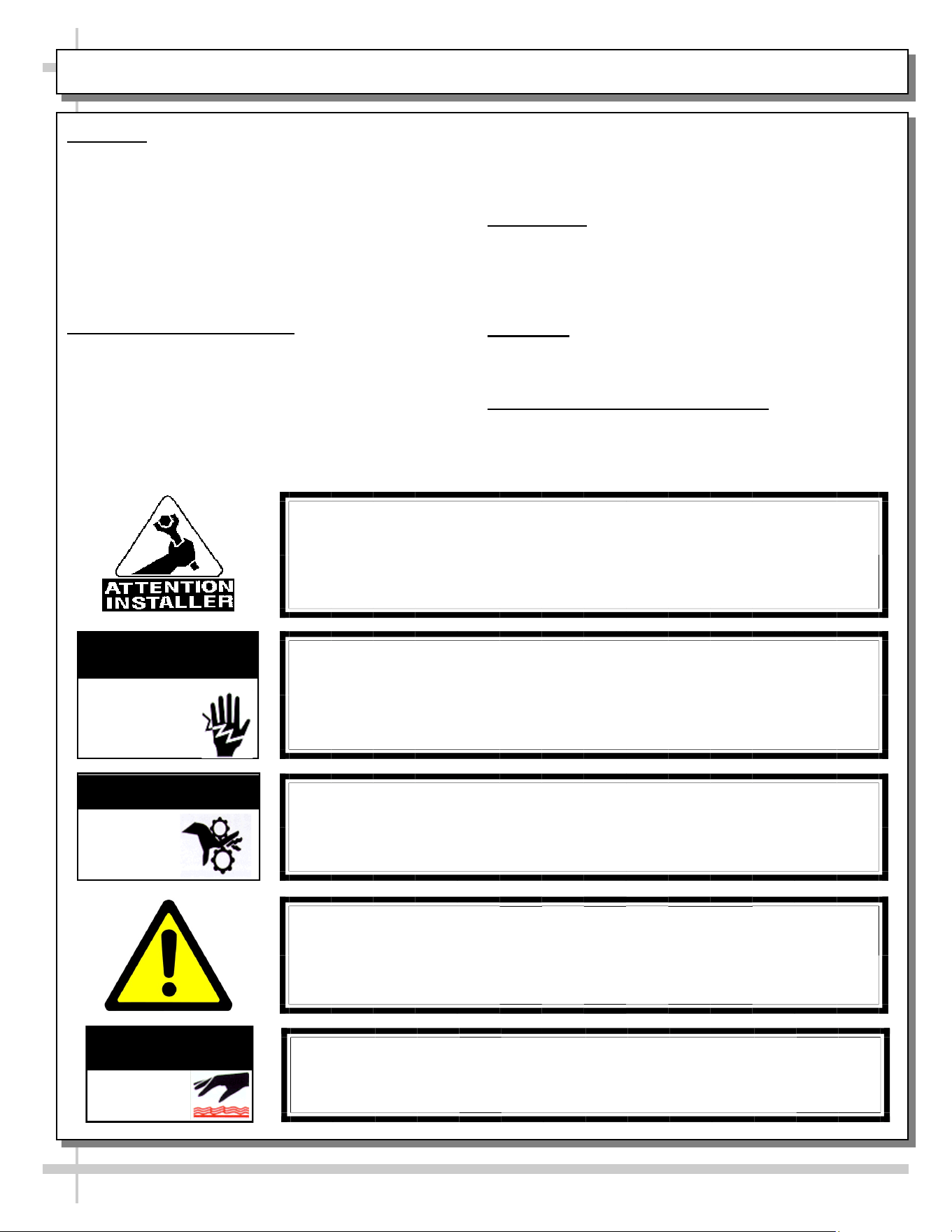
WARNINGS
• This page contains important warnings to prevent injury or
death. Please read carefully!
PRECAUTIONS and WIRING DIAGRAMS
• See next page for PRECAUTIONS and WIRING
DIAGRAM information.
WARNING
Hazardous moving parts. Do not operate unit with covers removed.
Fan blades may be exposed when deck panel is removed.
Disconnect power before removing deck panel.
WARNING
Risk of electric shock. Disconnect power before servicing unit.
CAUTION! More than one source of electrical supply is
employed with units that have separate circuits.
Disconnect ALL ELECTRICAL SOURCES before servicing.
WARNING
ELECTRICAL
HAZARD
WARNING
KEEP
HANDS
CLEAR
COMPLIANCE
This equipment MUST be installed in compliance with
all applicable NEC, federal, state and local
electrical and plumbing codes.
OVERVIEW / TYPE / COMPLIANCE / WARNINGS / PRECAUTIONS / CORDS / WIRING - PAGE 1 of 2
WARNING
This product can expose you to chemicals, including
Urethane (Ethyl Carbamate), which are known to the state of
California to cause cancer and birth defects or other reproductive
harm. For more information go to P65Warnings.ca.gov.
WARNING
Condensate pan and overflow condensate pans are HOT!
Disconnect and allow to cool before cleaning or removing from case.
WARNING
HOT
SURFACE
PRECAUTIONS
• Following are important precautions to prevent damage
to unit or merchandise. Read carefully!
• See previous page for specifics on OVERVIEW,
CONDITION TYPE, COMPLIANCE and WARNINGS.
WIRING DIAGRAM
• Each case has its own wiring diagram folded and in its
own packet. It may be placed near ballast box, field
wiring box, raceway cover, or other related location.
REFRIGERANT DISCLOSURE STATEMENT
• This equipment is prohibited from use in California with
any refrigerants on the “List of Prohibited Substances” for
that specific end-use, in accordance with California Code
of Regulations, title 17, section 95374.
• This disclosure statement has been reviewed and
approved by Structural Concepts and Structural Concepts
attests, under penalty of perjury, that these statements
are true and accurate.
OVERVIEW / TYPE / COMPLIANCE / WARNINGS / PRECAUTIONS / CORDS / WIRING - PAGE 2 of 2
4
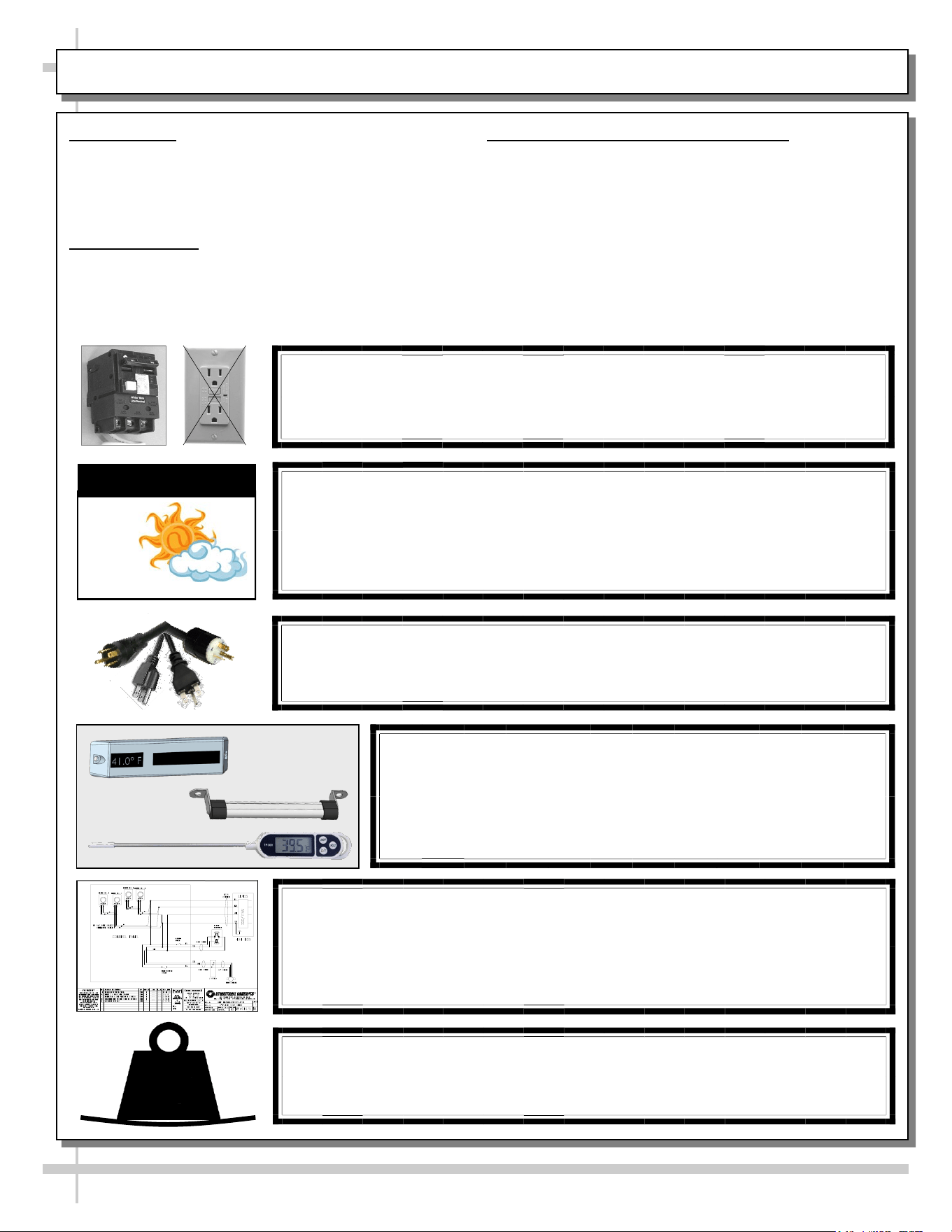
CAUTION! POWER CORD AND PLUG MAINTENANCE
Risk of electric shock. If cord or plug becomes damaged,
replace only with cord and plug of same type.
CAUTION! GFCI BREAKER REQUIREMENT
If N.E.C. (National Electric Code) or your local code
requires GFCI (Ground Fault Circuit Interrupter) protection,
you MUST use a GFCI breaker in lieu of a GFCI receptacle.
CAUTION! ADVERSE CONDITIONS / SPACING ISSUES
• Performance issues caused by adverse conditions are NOT warranted.
• Case must not be exposed to direct sunlight or any heat source.
• To maintain proper case temperature, keep case at least 15-feet from exterior
doors, overhead HVAC vents or any air curtain disruption.
CAUTION
CAUTION! DO NOT RELY ON THERMOMETERS OR
THERMOSTATS FOR PRODUCT (FOOD) TEMPERATURES.
• Thermometers & thermostats reflect air temperatures ONLY.
• For ACTUAL product (food) temperatures, use a calibrated food
probe thermometers ONLY.
• For accurate readings, DO NOT use infrared food thermometers.
WIRING DIAGRAM FORMAT & LOCATION
• Each case has its own wiring diagram folded and in its own packet.
• Wiring diagram placement may vary; it may be placed near ballast
box, field wiring box, raceway cover, or other related location.
• See sample wiring diagram at left (for illustrative purposes only).
CAUTION!
To prevent sagging, do not exceed 5 LBS (2.3 KG) weight load
per top glass section (between posts and/or supports).
5
LBS
5
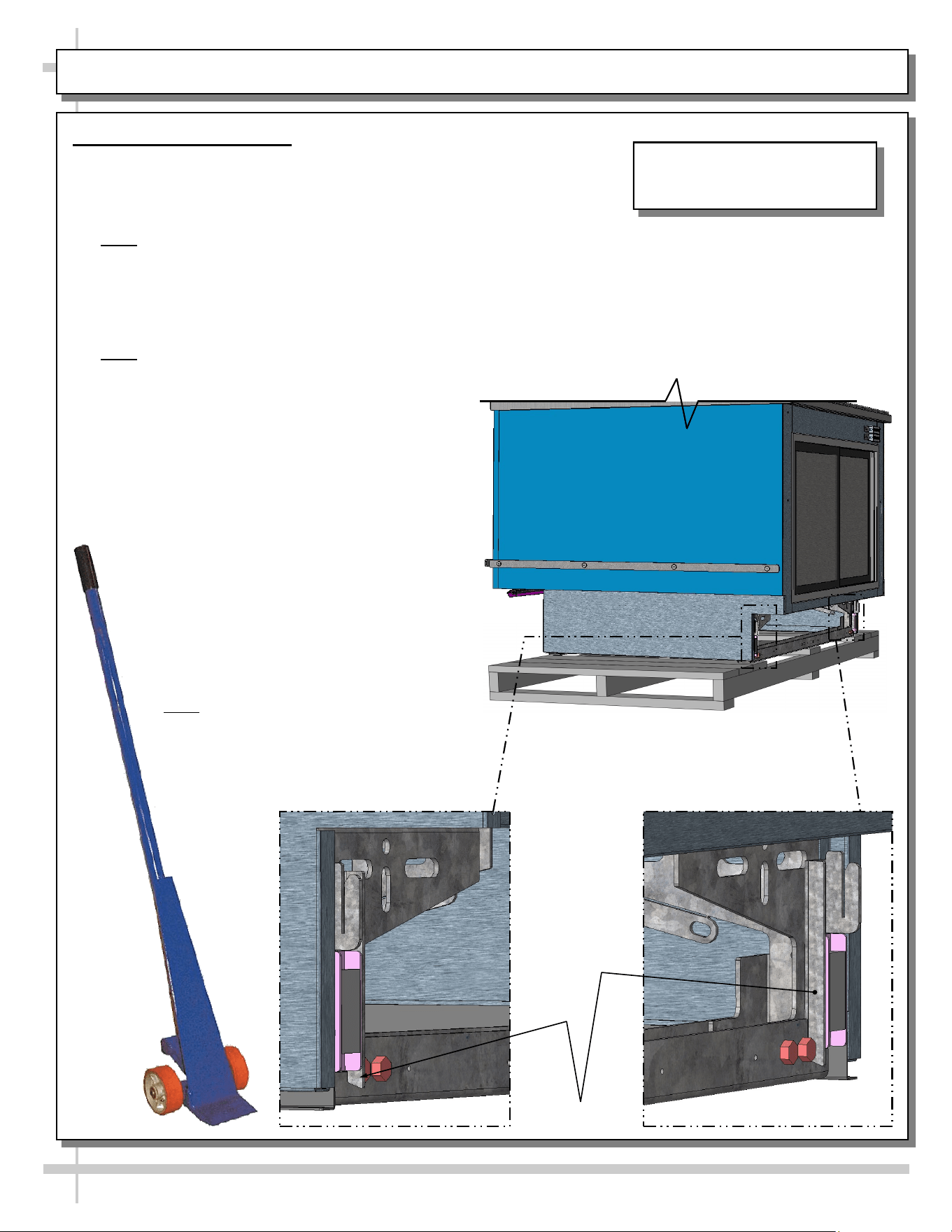
CASE REMOVAL FROM SKID / POSITIONING / FORK LIFT / J-BAR or DOLLY
J-Bar Lift Tabs
Remove Case From Skid
Fork Lift
• To lift case up for lift-truck forks to slide into position,
place J-bar, pry bar or dolly under J-Bar lift tabs
(location shown below).
• Note: REAR lift tabs are extended beyond base
frame bolts (to allow greater access).
• Raise case up to allow forks to slide under rails.
• Insert forks under rails.
• Make certain case is well-supported on forks.
Move case to desired location. Lower in place.
• Note: Illustration shown may not reflect every
feature or option of your particular model.
J-Bar, Pry Bar or Dolly Only (No Fork Lift)
• Caution! Do not push or pull on glass while
moving case into position!
• With several people in position, carefully
slide frame support rail to edge of skid.
• Slide case off skid and lower frame
support to floor.
• Once the frame support rail rests on the
floor, have several people supporting
front of case while skid is slid out from
under case.
• After case is off skid, several people
may be required to slide into position.
• Or, depending upon case weight, use
J-Bar to incrementally lift and rotate
case into desired position.
• Note: Illustrations shown may not
exactly reflect every feature or option of
your particular case.
Illustration Shown May Not
Reflect Every Feature Or Option
of Your Particular Case.
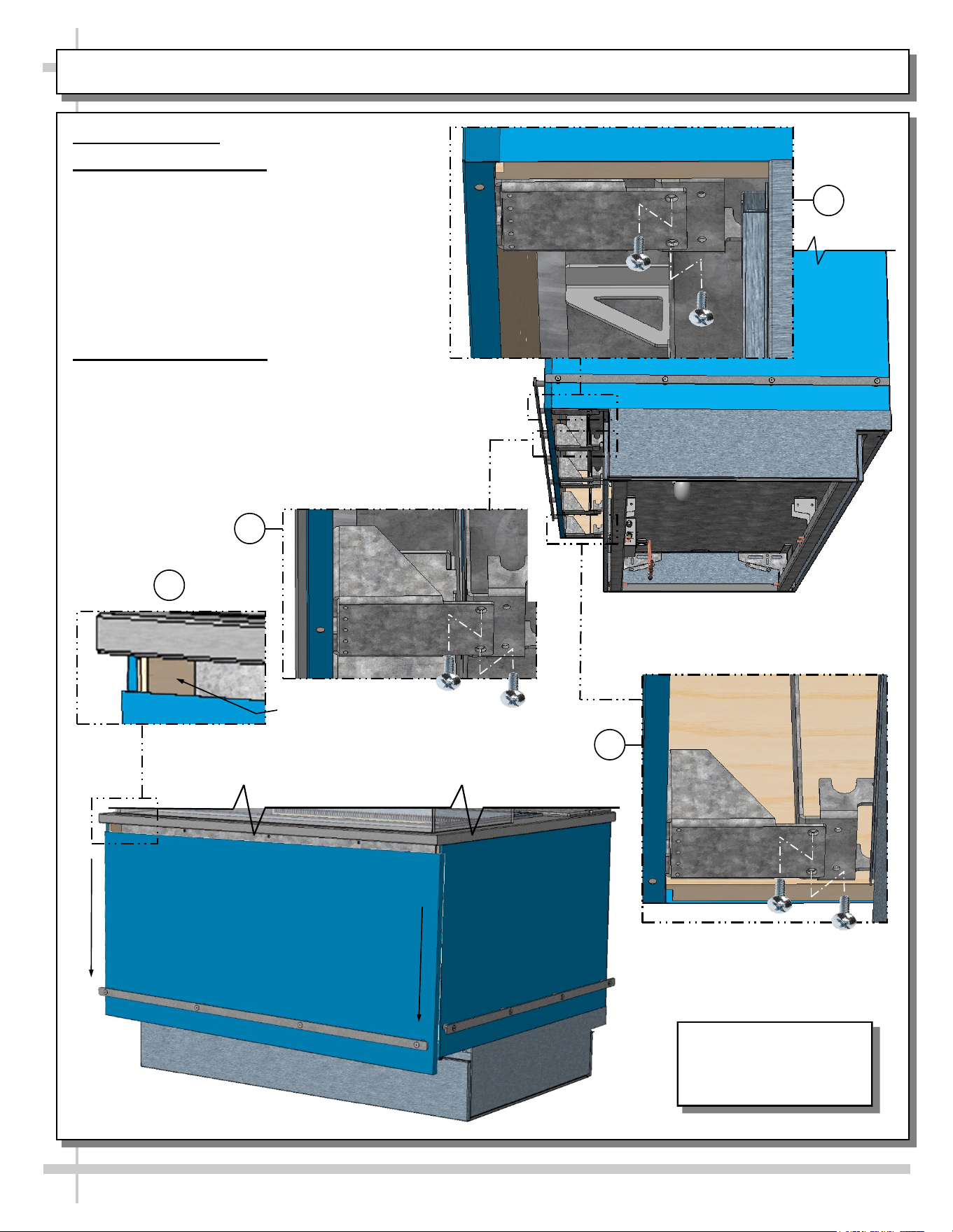
Illustration Shown May
Not Reflect Every
Feature Or Option of
Your Particular Case.
6
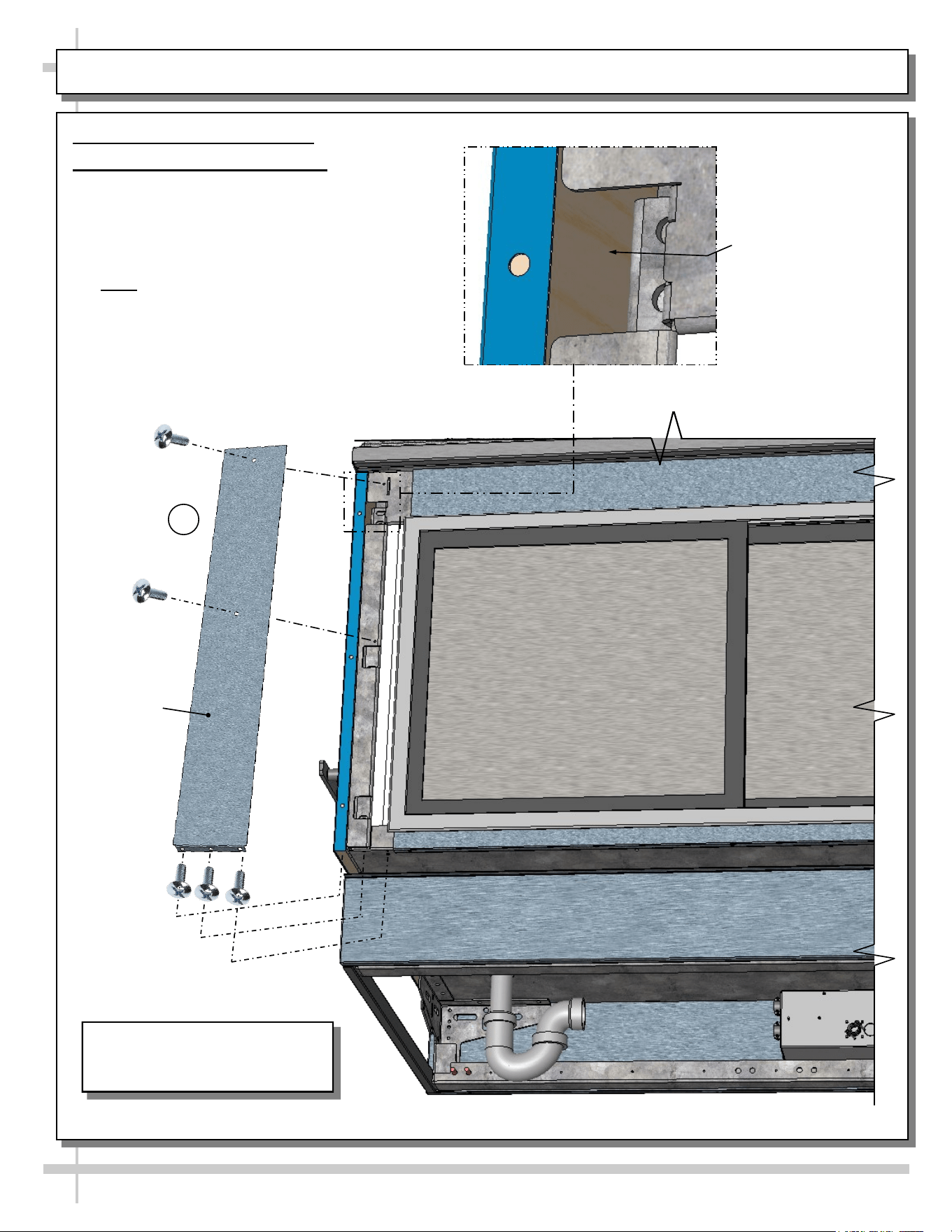
ADJOINMENT GUIDE: LOWERING FRONT PANEL FOR END PANEL ADJOINMENT
Adjoinment Guide
1. Lowering Front Panel
• Lowering front panel allows screws to be
inserted through inner end panels and into
adjacent cases.
• To do so, you must first remove two (2)
screws from brackets located at front
underside of case.
• Number of brackets vary depending upon
case length.
2. Adjoining End Panels
• Use wood screw to attach to adjacent case.
• After adjoining screw has been attached, raise front
panel back up and reattach (2) screws in each
bracket.
• Drill bits and screws are provided in lineup kit.
• Number of brackets vary depending upon case
length.
*
Inner End Panel
Adjoinment Spot (At Both
Ends) After Front Panel Is
2
1
1
1
Screw Locations
(Remove To Lower The Front Panel)
7
ADJOINMENT GUIDE, CONTINUED: REAR ADJOINMENT ACCESS (VIA COVER PLATE REMOVAL)
Adjoinment Guide, Continued
3. Rear Adjoinment Cover Plate
• Removal of rear adjoinment cover plate
allows access to inner end panels (at both
ends of case).
• Attach through end panel to adjacent case
end panel with wood screws.
• Note: Drill bits for pilot holes and wood
screws are included in adjoinment kit.
• Return rear adjoinment cover plate to case in
reverse order it was removed.
*
Apply Wood Screw
Through Inner End
Panel After Rear
Adjoinment Cover Plate
Has Been Removed
Illustration Shown May Not
Reflect Every Feature Or Option
of Your Particular Case.
Rear
Adjoinment
Cover Plate
3
8
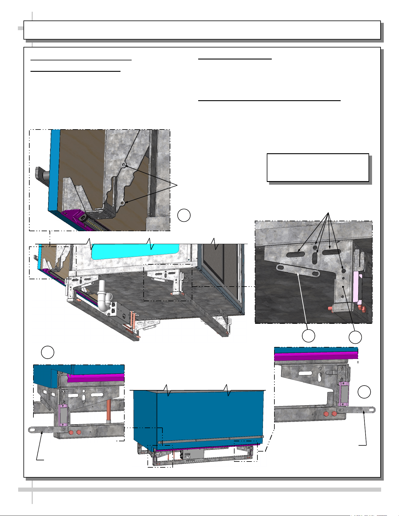
ADJOINMENT GUIDE, CONTINUED: BASE FRAME / GUSSET / BREAKOFF ADJOINMENT BRACKET
Adjoinment Guide, Continued
4. Base Frame Adjoinment
• Base frames (at both ends of case) have many
holes and obrounds to adjoin to adjacent case
base frames.
• Use 5/16”ø bolt to adjoin base frames.
Gusset Holes For Wood
Screw Attachment To
Adjacent Case’s End Panel
Base Frame Holes For 5/16”ø
Bolt Adjoinment Into Adjacent
Case’s Base Frame
Breakoff Adjoinment
Bracket: Use
SCC-Supplied 1/4-20
Screws To Attach To
Adjacent Case.
4
5
6
6
5. Gusset Adjoinment
• Gussets (at both ends of case) have holes for wood
screws to attach to adjacent case’s end panel.
• See illustration at top-left.
6. Breakoff Adjoinment Bracket (Optional)
• An adjoinment bracket comes from the factory
attached to base frame.
• As an option, it may be broken off and attached to
the front base frames of adjoining cases.
• See illustrations below.
--- Case Front ---
Breakoff Adjoinment
Bracket (Shown Attached
To Front of Case)
6
Illustration Shown May Not
Reflect Every Feature Or Option
of Your Particular Case.
General Tub
Area
9
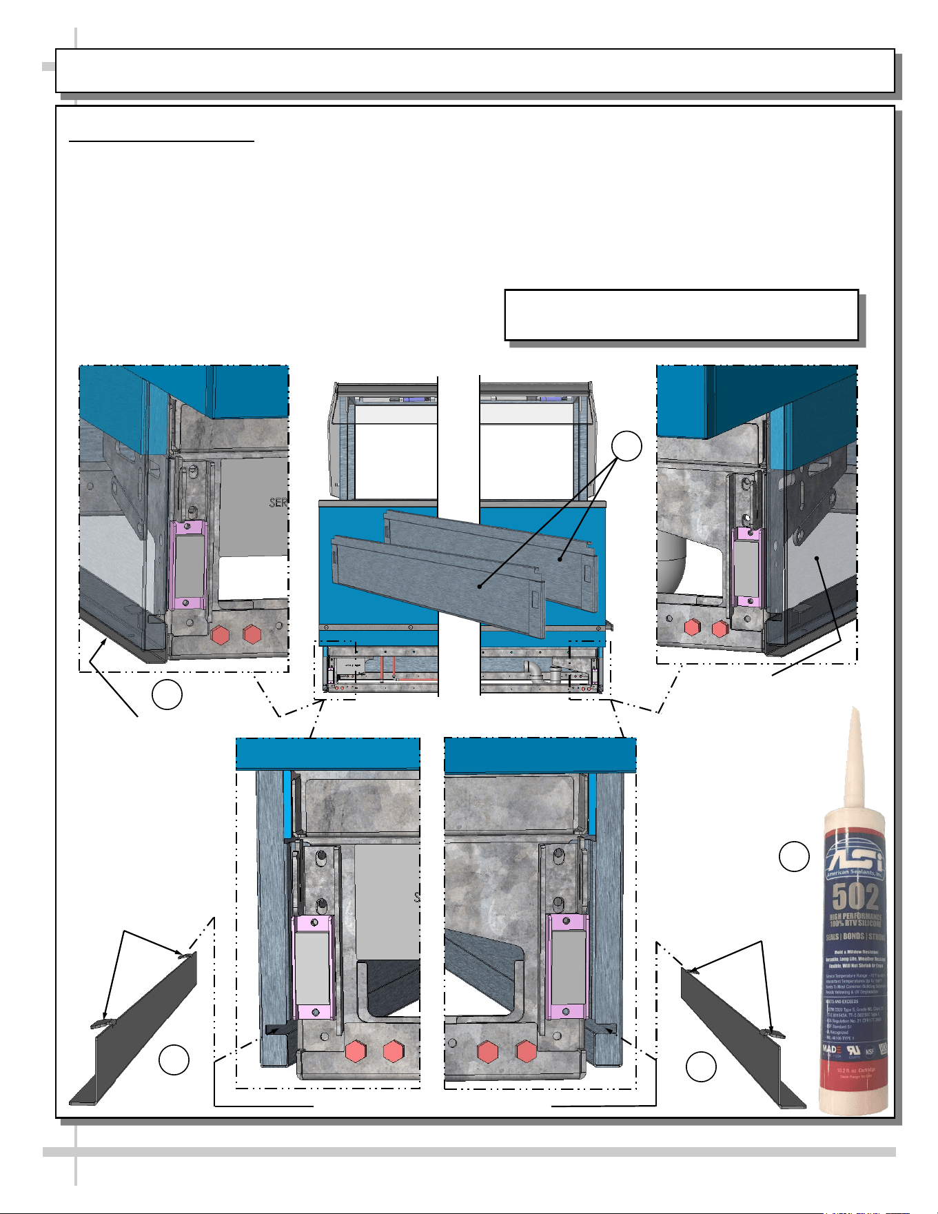
SPLASH GUARD BRACKETS: INSERTION AT CASE FRONT / ADJUSTABILITY / SEALING TO FLOOR
Case Front Views
Splash Guard Bracket
Shown Inserted Into
Base End Panel And
Flush To Floor
Splash Guard Brackets
• The separately shipped splash guard brackets are
designed to prevent entry or leakage of liquid or
moisture to underside of case.
• Case must be properly positioned and frame
support rails shimmed before bracket placement.
• Follow these instructions for proper splash guard
placement.
1. Remove front toe-kick (slot/hook/magnet method).
2. Insert the separately shipped splash guard
brackets into the base end panel slots.
3. Slide splash guard brackets into base end panels
until tabs drop into panel slots. Splash guard
brackets will now self-adjust flush to floor.
4. Raise splash guards upward and apply a bead of
industrial grade silicone sealant to underside.
Press splash guards bracket firmly to floor.
>> Replace front toe-kick.
1
2
2
Base End Panel
(Shown Transparent)
With Splash Guard
Bracket Shown
Inserted Inserted And
Flush To Floor
3
Tabs
Tabs
4
Model FB8SS-6R Is Shown. It May Not Reflect
Every Feature Or Option of Your Particular Case.
Slots For Splash Guard Bracket Tabs
10
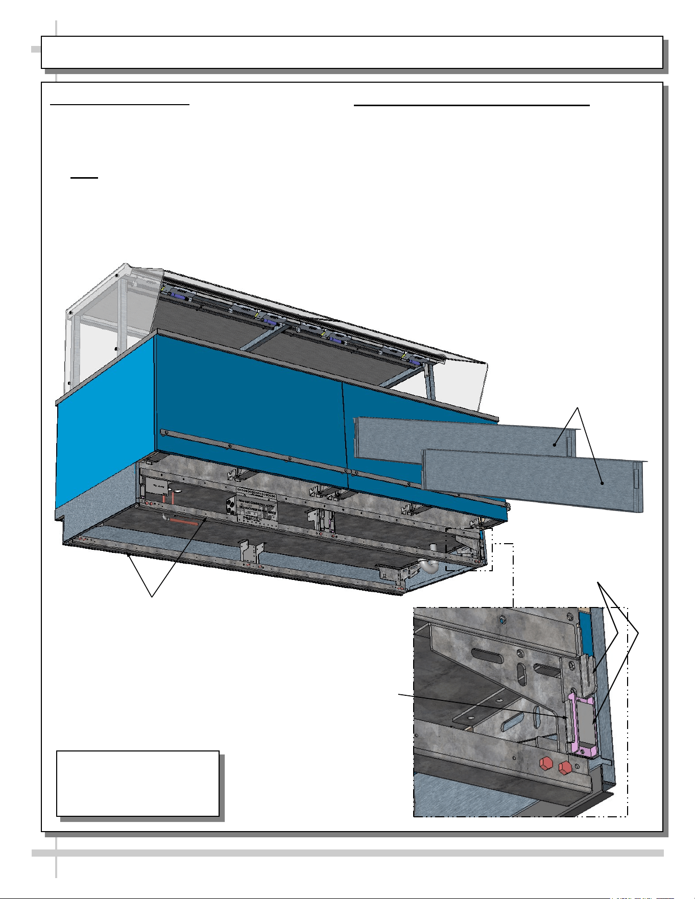
FRAME SUPPORT RAILS / REMOVABLE FRONT AND REAR TOE-KICKS
1. Frame Support Rails
• Illustration below shows random case with frame
support rails at underside.
• Frame support rails must be shimmed.
• Shims will be provided with all cases.
• Note: After case is in position, it must be
sealed to floor to prevent entry or leakage of
liquid or moisture.
2. Removable Front and Rear Toe-Kicks
• Front and rear toe-kicks consist of slots that may
be lifted up and off case hooks (no screw removal)
and separated from magnets.
• Illustration below shows front toe-kicks being
removed.
• Return to case after accessing for cleaning or
service.
Front Toe-Kick Hook
and Magnet (No Screw
Removal Required)
Frame Support
Rails (Typ.)
Removable Front Toe-Kick
Shown Removed From Case
(And Reversed For Illustrative
Purposes Only)
J-Bar / Fork-Lift
Tab (Typ.)
Model FB8SS-6R Is Shown.
It May Not Reflect Every
Feature Or Option of Your
Particular Case.
11
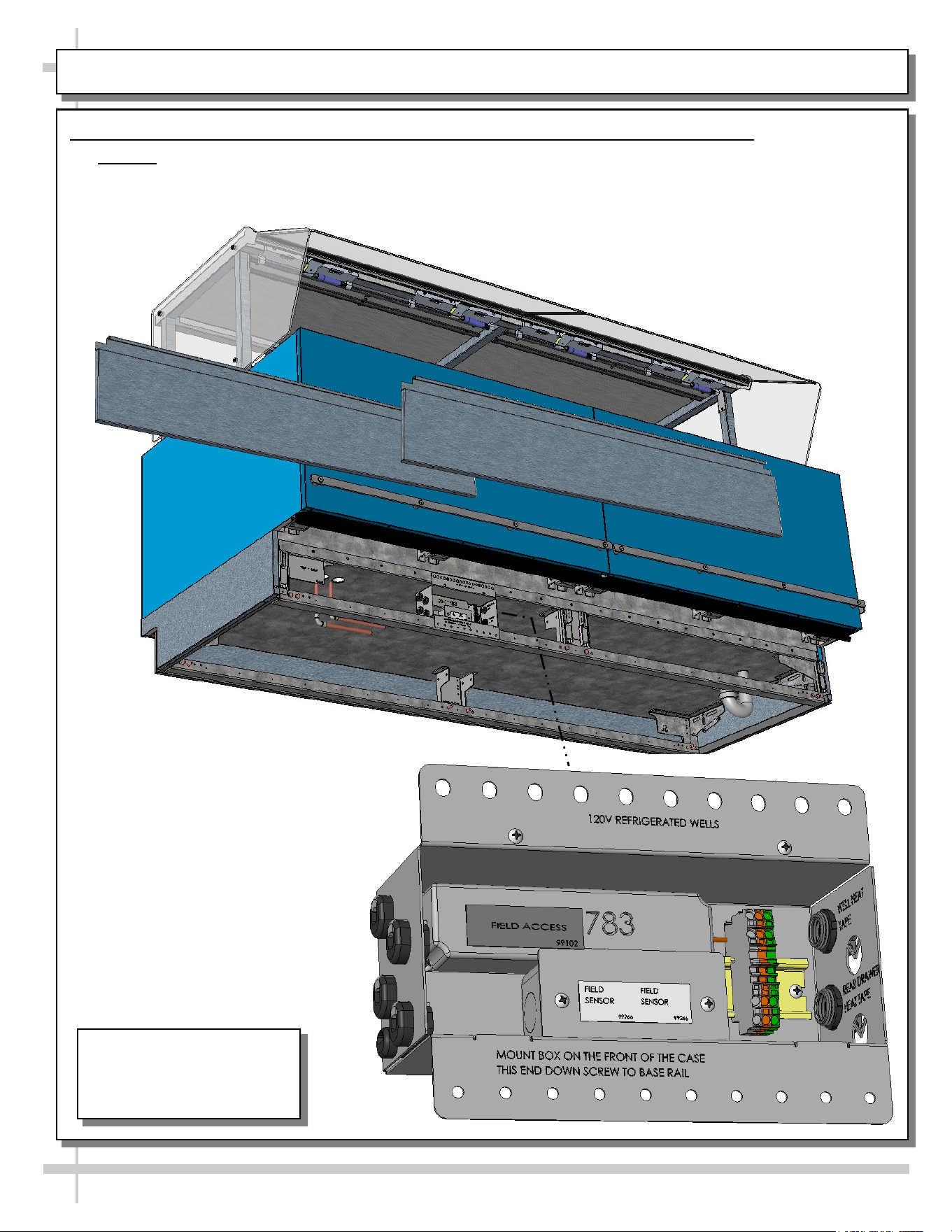
ELECTRICAL OVERVIEW: FIELD ACCESS / DRIVERS / FIELD SENSOR / T-STRIP
1. Electrical Overview: Field Access Box / Drivers / Field Sensor Box / Terminal Strip
• Caution! Only certified electricians are to perform electrical connectivity duties.
• Remove front panels (via hook/magnet method) to access field access box (see previous page).
• Remove screws at front of field access boxes allows access to drivers and other electrical components.
Model FB8SS-6R Is Shown.
It May Not Reflect Every
Feature Or Option of Your
Particular Case.
12
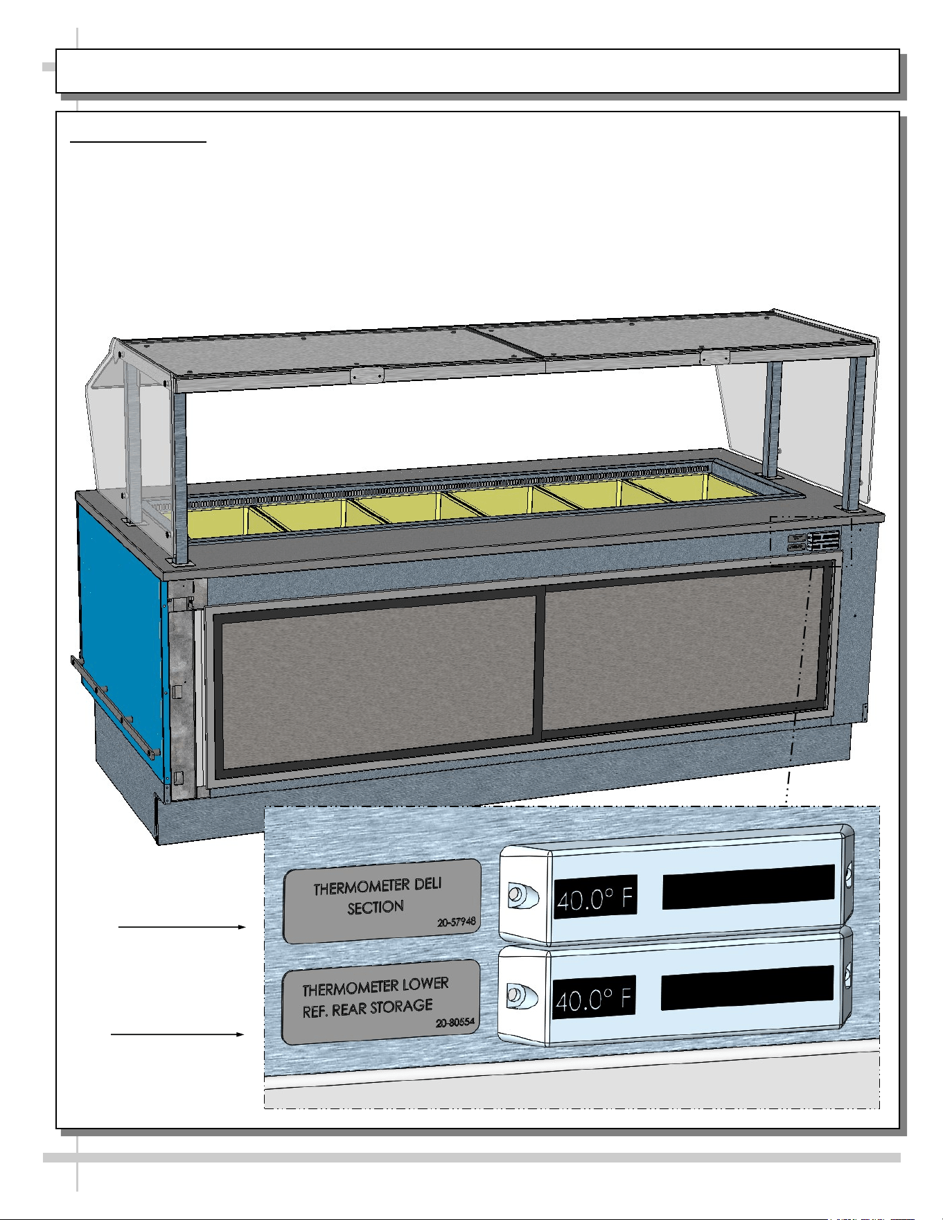
ELECTRICAL OVERVIEW, CONTINUED: THERMOMETERS
2. Thermometers
• Upper digital thermometer displays temperatures of the refrigerated upper section (with pans & dividers).
• Lower digital thermometer displays temperatures of lower refrigerated rear storage.
• Thermometer directly above refrigerated storage compartment measures case’s internal temperature.
• Thermometers are for monitoring internal air temperature only (not actual food temperature).
• Use probe thermometers to determine actual product temperatures.
• See illustration below for general locations.
Upper Thermometer
For Refrigerated
Wells (Deli) Section
Lower Thermometer
For Rear Refrigerated
Storage Section
TXV
13
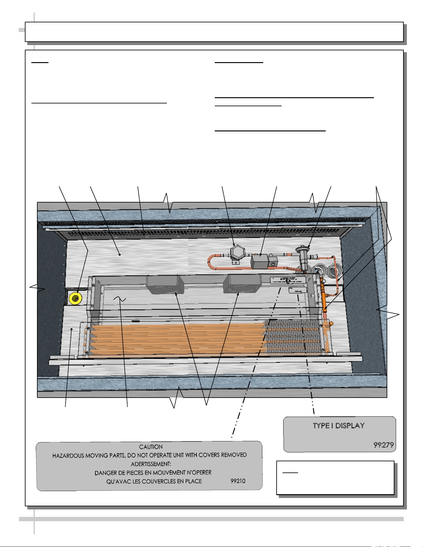
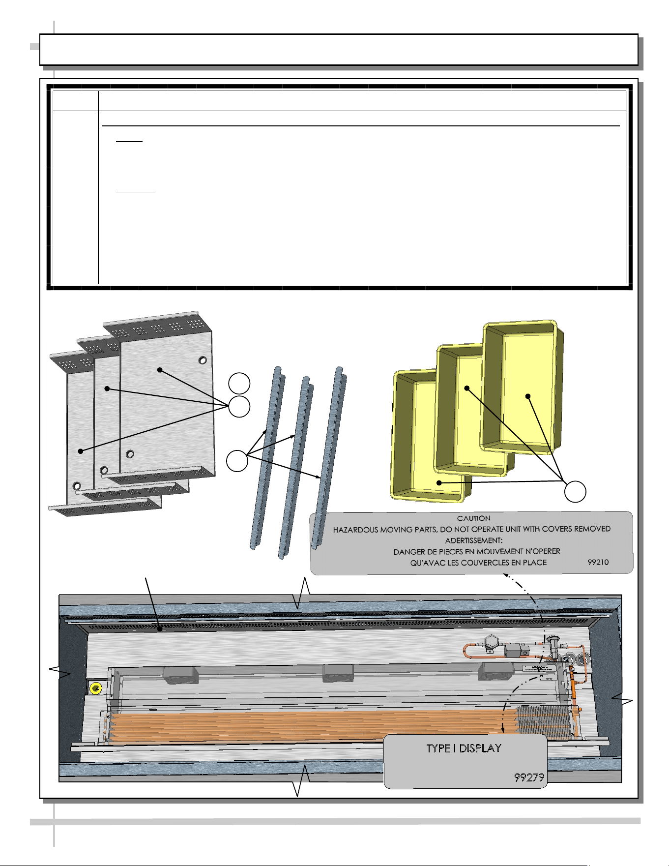
START-UP & OPERATION - REFRIGERATED UPPER SECTION
Note: Exact location of fans, refrigeration lines,
coil, shroud, valves and thermometer may vary
depending upon your case.
Merchandiser Start-Up and Operation
1. Powering Up Refrigerated Section
• Refrigeration upper section energize when
field-wired.
• Listen for fans to verify that unit is energized.
2. Axial Fans
• After removal of pans, axial fans are accessible.
• See transparent illustration below.
3. Refrigeration Lines, Solenoid Valve, TXV,
Shutoff Valve, Etc.
• See illustration below for locations.
4. Cleaning Refrigeration Area
• Refrigeration area must be cleaned regularly.
• See cleaning schedule in this manual for specifics.
Refrigeration
Lines
Shutoff Valve
Axial Fans
(Typ.)
Drain
Evaporator Fan Shroud
(Shown Transparent)
Solenoid Valve
Inner Perforated
Panel (Typ.)
Tub
Tub
*
**
Note: Illustration Shown May Not
Reflect Every Feature Or Option
of Your Particular Case.
14
REFRIGERATED REAR SECTION WITH SLIDING DOORS
Rear Refrigeration Section With Removable Sliding Doors
• Sliding doors are removable for cleaning or service.
• See illustration below.
Model FB8SS-6R Is Shown In
This Illustration. It May Not
Reflect Every Feature Or Option
Of Your Particular Case.
Rear Sliding Doors (Removed For
Illustrative Purposes)
15
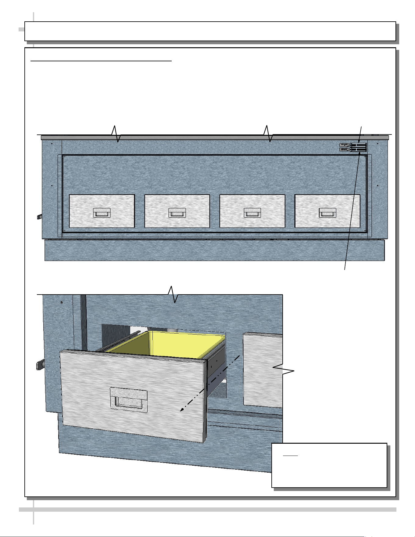
REFRIGERATED REAR SECTION WITH DRAWERS
Refrigerated Rear Section With Drawers
• Rear drawers are able to be slid out and/or removed for cleaning.
• See GENERAL CLEANING SCHEDULE: DAILY “D” / WEEKLY “W” for cleaning instructions.
Note: Random Model Shown.
Illustration Shown May Not
Reflect Every Feature Or Option
of Your Particular Case.
--- Rear View of Random Case ---
--- Rear Left View of Random Case ---
Upper Thermometer
For Refrigerated
Wells (Deli) Section
Lower Thermometer
For Refrigerated Rear
Section With Drawers
16
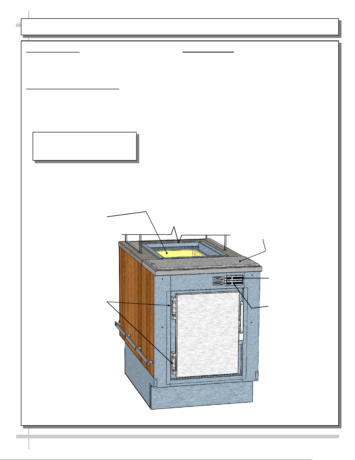
REFRIGERATED REAR SECTION WITH HINGED DOOR
1. General Layout
• Refrigerated wells, compartment and drawer,
sneeze guard, Sanalite® rear ledge, drain valve,
thermometers, etc., are shown below.
2. Cleaning Refrigeration Area
• Refrigeration area must be cleaned regularly.
• See cleaning schedule in manual for specifics.
3. Thermometers
• Upper digital thermometer displays temperatures
of the refrigerated upper section (with pans and
dividers).
• Lower digital thermometer displays temperatures
of the rear refrigerated section (either behind
sliding doors or hinged door).
• Thermometers are for monitoring internal air
temperature only (not actual food temperature).
• Use probe thermometers to determine actual
product temperatures.
• See illustration below for general locations.
Upper Thermometer
For Refrigerated
Wells Section
Rear Hinged Door To
Refrigerated Section
Refrigerated
Well
Sanalite® Rear
Ledge (Typ.)
Lower Thermometer
For Rear Refrigerated
Section (Door)
Model Shown In This Illustration May
Not Reflect Every Feature Or Option
of Your Particular Case.
17
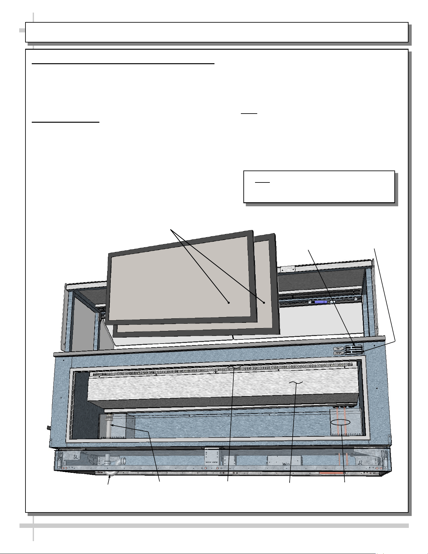
REAR REFRIGERATED “SHARED AIR” SECTION / SLIDING DOORS / THERMOMETERS
• Thermometers & thermostats reflect air
temperatures ONLY.
• For ACTUAL product (food) temperatures,
place probe directly in food product. Do not
solely rely on air temperature on thermometer
for accurate product temperature
• Note: Should food temperatures significantly
vary from acceptable range, contact SCC
Technical Service. See SCC TECHNICAL
SERVICE CONTACT INFORMATION section
of this manual for specifics.
• See illustration below.
1. Rear Refrigerated Section - With Shared Air
• Certain units have rear refrigerated section that
“shares air” with upper tub area.
• Refrigerated air flows through upper perforated
panel into lower/rear storage refrigerated section.
• See illustrations below.
2. Thermometers
• Upper thermometer reflects temperature of upper
refrigerated section.
• Lower thermometer reflects temperature of lower
refrigerated rear storage area.
• Thermometer reflects air temperature only.
• Caution: Do not rely on thermometer for actual
product (food) temperatures.
Rear Sliding Doors (Removed
For Illustrative Purposes)
Refrigeration
Lines From
Inside Tub
Drain Pipe From
Inside Tub To
Underside P-Trap
P-Trap
Upper Perforated
Panel From
Inside Tub
Thermometer To
Upper Refrigerated
Section
Thermometer To
Lower Refrigerated
Rear Storage Area
Tub Housing
Note: Model FB8SS-6R Is Shown In This
Illustration. It May Not Reflect Every Feature
Or Option Of Your Particular Case.
18
CLEANING SCHEDULE: DAILY “D” / WEEKLY “W”
Area D W Task
Case
Exterior
X Wood / Laminate/ Painted Surfaces, etc.: Clean with a warm soap and water
solution and soft cloth. Never use wire cloth or abrasive cleaners on case.
X Glass Sneeze Guard (Front/Sides/Top): Clean with a household or
commercial glass cleaner.
X Stainless Steel Surfaces: See CLEANING SCHEDULE: STAINLESS
STEEL - TO BE PERFORMED BY STORE PERSONNEL section in this
manual for cleaning and care instructions.
X Quartz Work Surfaces: Depending upon your particular stone, see
• CLEANING PROCEDURE - CAMBRIA® NATURAL QUARTZ SURFACE
• CLEANING SCHEDULE: CAESARSTONE® SOLID SURFACE or
• GENERAL GRANITE, MARBLE & STONE SURFACE CLEANING, CARE
& MAINTENANCE in this operating manual.
Case
Interior
X Refrigerated Prep Area (Pan, Pan Covers and Pan Dividers, Decking, etc.):
See CLEANING SCHEDULE: DAILY / WEEKLY: DECK PANS / DIVIDERS /
PRODUCT PANS / TUB section in this operating manual for cleaning specifics.
X Refrigerated Rear Drawers or Doors: Wipe down with a warm soap and wa-
ter solution and soft cloth. Dry with soft cloth or paper towel.
X Rear Section (Accessible via Sliding or Hinged Doors or Drawers): Wipe
down with a warm soap and water solution and soft cloth. Dry with soft cloth or
paper towel.
X Under Case Cleaning: Remove front (or rear) lower panels. Use vacuum or
broom to clean flooring under case. Do not allow broom to create dust in store!
X Refrigeration Prep Area (Tub, Trough, Drain, Components, Perforated
Plenums, etc.):
• See CLEANING SCHEDULE - DAILY / WEEKLY: PANS / DIVIDERS /
DECK / PERFORATED PLENUMS / TUB section in this manual for
cleaning specifics.
19
CLEANING & MAINTENANCE of NATURAL QUARTZ (AND OTHER STONE) SURFACES
Routine
Care
For Daily, Routine Cleaning:
• Natural quartz (and other stone) surfaces require very little maintenance. Simply wipe surfaces with soap and
warm water on a regular basis to maintain its shine. Any pH balanced general-purpose household cleaner may
be used.
Chemicals
To Avoid
Chemicals To Avoid:
Avoid exposing natural quartz (and other stone) surfaces to strong chemicals and solvents.
• Items to avoid include: nail polish remover, permanent markers or inks, oil soaps, and furniture cleaners or
paint strippers that contain trichlorethane or methylene chloride.
• Also avoid exposing surface to chemicals with high alkaline/PH levels, i.e., oven cleaners.
Caution must be used with the following products:
• Avoid using products containing oils or powders as may leave a residue.
• Avoid repetitive use of abrasive scrubs/cleaners as they may dull the finish.
• Avoid oven/grill cleaners as they may discolor the finish.
• Avoid exposure to extreme heat as it may damage the finish.
Apparent stains like coffee, food, makeup, etc.:
• Apply the appropriate cleaner with a paper towel and wipe. If necessary, the area may be soaked with pads of
paper towels from 3-10 minutes;
• Scrub the area. Rinse thoroughly. Dry thoroughly.
Difficult
Spills
For Difficult Spills:
To remove difficult spills on natural quartz (and other stone) surfaces, follow these guidelines.
• Wipe the surface with warm water and soap. If needed, apply a common household cleaner.
• For stains that harden as they dry (such as food, gum, nail polish, and paint), remove by gently scraping off of
surface (using a blade or putty remover), and then clean using warm water and soap. Gray marks lefts by the
razor, can be wiped away with soap and water.
• Natural quartz (and other stone surfaces) are resistant to damaging chemicals. Difficult spots may be treated
with one of the cleaners listed below:
> Rubbing Alcohol > Ammonia > Vinegar
Note: Allow the desired cleaner to sit for up to 10 minutes. Scrub and rinse thoroughly. Dry thoroughly.
Cleaning
Cases With
Silicone
Cleaning Cases With Silicone In And Around Surfaces:
• Cases with silicone between inserts and the surrounding natural quartz (and other stone) surfaces should be
cleaned with any of the following:
> Soapy water (e.g., Dawn® dish soap and warm water) > Simple Green® All Purpose Cleaner > Ammonia
> Rubbing Alcohol > Vinegar > Any solution containing more than 90% IPA (iso-propyl alcohol)
• Solutions and cleaners to AVOID while cleaning cases with silicone in and around natural quartz
(and other stone) surfaces include the following: > Acetate > Lacquer Thinner > Mineral Spirits
> Paint Thinner > Windex® Without Ammonia (Windex® WITH Ammonia is Acceptable) > Formula
409® > Fantastik® > Bleach > Citrus cleaners (or Cleaners With Citrus in it )
Extreme
Heat
Protection
Extreme Heat Protection:
• Natural quartz (and other stone) surfaces are extremely resistant to heat, and can withstand moderately high
temperatures for brief periods of time without being damaged.
• Although natural quartz (and other stone) surfaces are more heat resistant than any many others, ALL stone
surfaces (including quartz) can be damaged by sudden and extreme temperature changes, especially near the
edges. For this reason, always use a trivet or a hot pad to protect surfaces from extreme heat.
Extreme
Scratch
Protection
Extreme Scratch Protection:
• Although natural quartz (and other stone surfaces) are extremely scratch resistant, surfaces should be
protected by using a cutting board to avoid damage to knives.
Rev A Date: 11.6.2018
CaesarStone® Care & Maintenance
TAKING CARE OF YOUR QUARTZ SURFACE
CaesarStone quartz surfaces blend modern sophistication
and timeless luxury with unbeatable strength and
durability. The ever-lasting finish requires only simple and routine care to maintain its good looks.
MINIMAL MAINTENANCE
Virtually maintenance-free, CaesarStone’s hard, non-porous surfaces require no sealing to renew the
luster and are simple to clean. In most cases, dip a clean, soft cloth into a solution of water and soap
(or mild detergent) solution and wipe away dust, smudges and residue; then rinse with clean water to
remove residue. This simple treatment is usually enough to keep your CaesarStone countertop
looking like new. If necessary, use a non-abrasive soft soap along with a non-scratch or delicate
scrub pad. Afterwards, thoroughly rinse with clean water to remove residue.
STUBBORN STAINS OR DRIED SPILLS
If needed, apply a non-abrasive household cleaners (a non-abrasive cleaner will not dull the surface
shine); rinse to remove residue. To remove adhered material such as food, gum, nail polish or even
dried paint, first scrape away excess material with a plastic putty knife and then use a damp cloth to
remove any marks or residual dirt. For extra-stubborn stains, use a no-scratch Scotch-Brite® pad
along with the non-abrasive cleaner recommended by your local CaesarStone® distributor.
HEAT TOLERANCE
CaesarStone is more heat resistant than other stone surfaces including most granite, marble and
limestone; it is not affected by temperatures lower than 300 °F (149 °C). However, like all stone
material, CaesarStone can be damaged by sudden and rapid temperature changes. Therefore, do not
place hot pots or pans directly placed on the surface. Instead place a hot pad or trivet on the surface
under cooking units such as electric frying pans, crock pots, or roaster ovens.
SCRATCH RESISTANT
CaesarStone is a highly scratch resistant surface; however avoid abuse of the surface by refraining
from using sharp objects such as sharp knives or screw drivers directly onto the surface.
CLEANING AGENTS TO AVOID
• It’s important to be aware that like any other surface, CaesarStone can be permanently damaged
if exposed to strong chemicals and solvents that can damage its physical properties.
• Never clean your CaesarStone surface with products that contain Trichlorethane or Methylene
chloride, such as paint removers or strippers.
• Avoid the use of highly aggressive cleaning agents such as oven/grill cleaners and dishwasher
polishing agents that have high alkaline/pH levels (pH 8.5 or higher).
• Products containing oils or powders may leave a residue and should be rinsed off thoroughly.
Should your surface accidentally be exposed to any of these damaging products, rinse
immediately with clean water to neutralize the effect.
CLEANING SCHEDULE: CAESARSTONE® SOLID SURFACE
20
21
CLEANING SCHEDULE: GRANITE, MARBLE & STONE SURFACE CLEANING, CARE & MAINTENANCE
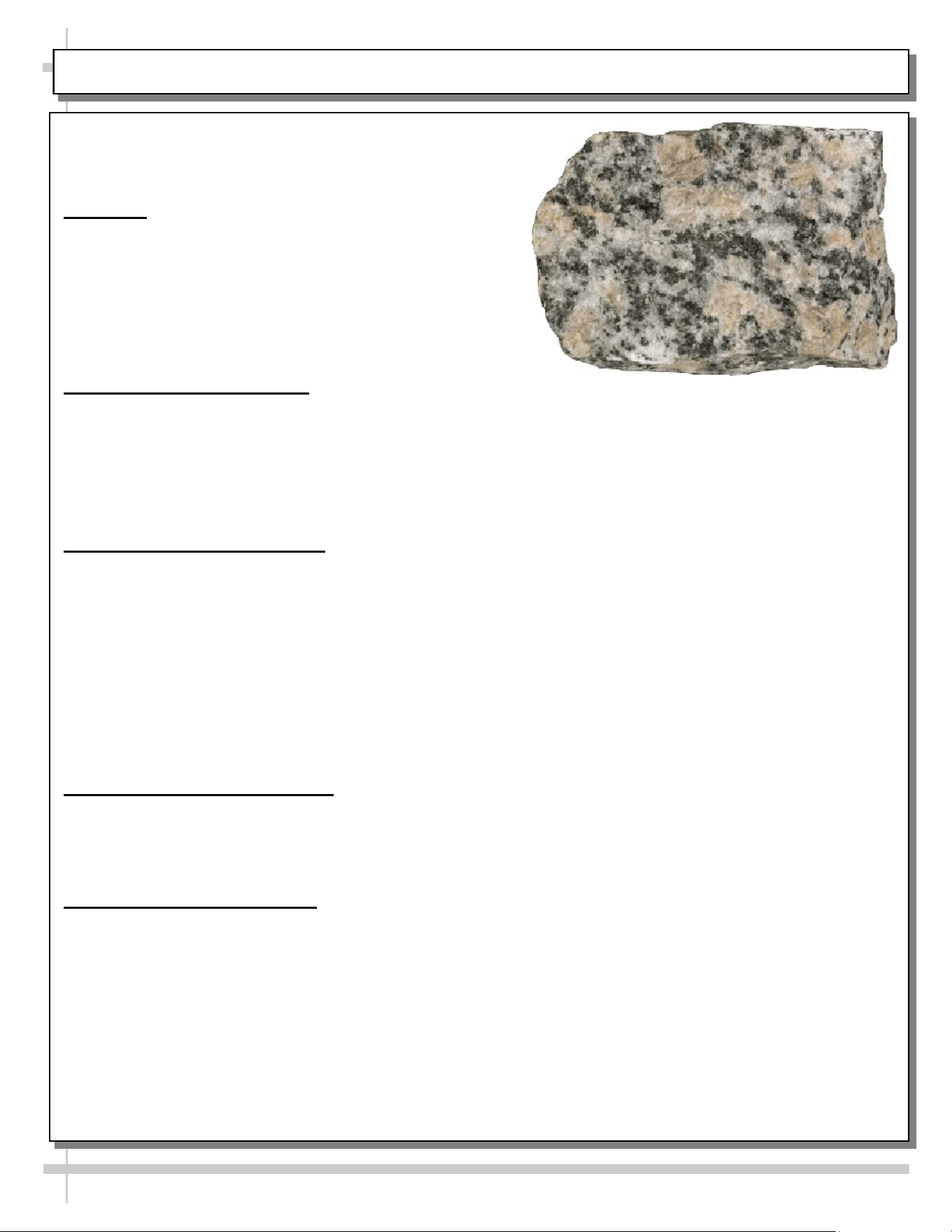
Granite, Marble & Stone Surface
Cleaning, Care & Maintenance
Overview
• Granite, marble and stone surface countertops are
functional, elegant and add a luxurious element to
any room. Each piece is one-of-a-kind with unique
color, detail and veining.
• Properly protected stone surfaces will stay beautiful
and well-maintained for years to come.
Immediate Cleanup of Spills
• Many common foods and drinks contain acids which can etch or dull stone surfaces.
• Wipe up acidic or alcoholic beverage spills quickly or rings and dull spots can form.
• Use coasters under glasses.
• Use a granite-specific cleaner cleaning solution for quick cleanups and to regularly clean the
surface. Daily maintenance prolongs the life of countertops.
General Cleaning Instructions
• Soils from dirt, dust and smoke may deposit a hazy film onto the surface. Clean and polish
regularly with a top-quality granite care product to keep the surface clear and shiny.
• Do not use ammonia-based cleaners like glass cleaner, high pH solutions, abrasive powders, soapy
detergents that may dull and damage the surface.
• Avoid using scouring pads, rough sponges and steel wool.
• Use only neutral pH products to clean granite. Avoid alkaline or acidic solutions as they can mar
and dull the seal.
• Many comments found on blogs list regular glass cleaner (such as Windex®) as being effective at
eliminating streaks left by bleach-wipes and other cleaners.
Preventing Damage To Surface
• While stone surfaces are generally heat-resistant, it is recommended to use trivets, “hot plates”, or
cloth placements under hot items.
• Use coasters under cups and glasses to prevent rings from forming on (and etching) surface.
Surface Care & Maintenance
• Always buff and dry granite after cleaning.
• Use a cleaner-and-polish-in-one to brighten the stone's natural color and veining while restoring its
glossy finish.
• Sealed granite is not immune to staining. Consult a stone countertop professional to determine
how often your countertop should be resealed. You may want to consider resealing when water
droplets no longer bead on the surface.
• For cracks, deep stains or signs of erosion, contact a stone care professional.
22
CLEANING SCHEDULE: STAINLESS STEEL
Stainless Steel Cleaning
General Stainless Steel Surface Cleaning (To Be Performed As Often As Needed):
• Certain grades of stainless steel are more prone to corrosion than others.
• Stainless steel can be exposed to many contaminants, which if left untreated can cause stains and rust.
• Stainless steel requires a specific cleaning procedure to maintain its sheen and remain rust-free.
• Wash with a solution of liquid dishwashing detergent and hot water.
• Rinse with pure hot water from spray bottle. Wipe with clean sponge. This will remove soap residue
that can lodge in stainless steel’s microscopic grooves, causing rust.
• Dry with clean, soft cloth or paper towel.
• Caution! To prevent rust, you MUST rinse with pure hot water from a spray bottle while wiping with
clean sponge after EACH cleaning.
• Caution! Never clean with scouring powder or steel wool as they mar, scratch and/or erode the surface
of stainless steel. When surface properties of stainless steel have been compromised, rust may form.
Brightening:
• Method 1: Brighten by polishing with a soft cloth or sponge with a solution of one part vinegar to 2 parts
water in a spray bottle.
• Method 2: Sprinkle baking soda on sponge and rub gently with soft cloth or sponge.
• Caution! To prevent rust, you MUST rinse with pure hot water from a spray bottle while wiping with
clean sponge after EACH cleaning.
• Dry with clean, soft cloth or paper towel.
Removing Streaks or Stains:
• Method 1: Place two teaspoons of rubbing alcohol on a microfiber cloth or pad. Rub the cloth along the
grain of the appliance until the entire area has been wiped. The rubbing alcohol will air dry itself.
• Method 2: Dip soft cloth or sponge in club soda and rub gently over area of concern.
• Caution! To prevent rust, you MUST rinse with pure hot water from a spray bottle while wiping with
clean sponge after EACH cleaning.
• Dry with clean, soft cloth or paper towel.
Polishing:
• Place a dab of olive oil onto clean soft cloth. Spread over area until a light sheen is observed. Use
pressure to “work the oil” into the small grooves in the surface. Apply firm, steady pressure using small
circular motions.
> Dry buff: Remove excess oil with clean cloth or paper towel using small circular motions.
> Wet buff: Use an ounce of white vinegar with clean cloth or paper towel using small circular motions.
> Continue wiping until oily finish has been removed.
• Caution! To prevent rust, you MUST rinse with pure hot water from a spray bottle while wiping with
clean sponge after EACH cleaning.
• Dry with clean, soft cloth or paper towel.
Removing Rust:
• If rust has begun to form, there are a variety of products that can treat it.
• Among these are CLR® (calcium, lime and rust remover) and Chemetall Oakite 33 (rust, oxides and
scale remover).
• Caution! To prevent food contamination, personal injury or further corrosion, carefully
observe and follow the rust-removing product’s precautions and instructions.
23
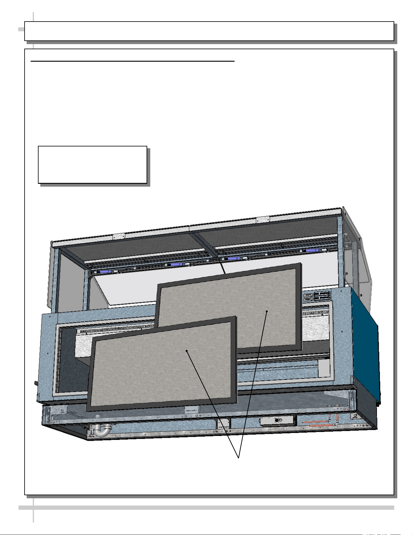
CLEANING SCHEDULE: DAILY / WEEKLY: DECK PANS / DIVIDERS / PRODUCT PANS / TUB
AREA INSTRUCTIONS
Deck
Pan /
Tub
Area
Follow These Steps To Clean Product Pans, Dividers, Perforated Plenums, Deck Pans, Etc.
1. Daily: Remove product pans and dividers and submerse them in warm, soapy water. Rinse.
Wipe down deck pans with warm, soapy water and cloth; rinse with spray bottle containing
clean water; dry. Wipe down deck pans (including perforated deck pan sides) with warm, soapy
water solution and clean cloth; rinse; dry. Return dividers and product pans to case.
2. Weekly: Trained Service Personnel Only - Disconnect Power To Case! After removing
product pans & dividers, remove deck pans (finger holes provided for easy removal).
Submerse all components in warm water, and clean with mild soap solution and soft cloth. Use
soft-bristled brush on hardened residue. Dry thoroughly. While components are removed from
case, wipe down tub, sides, components, trough and drain with warm, soapy water solution
and cloth. Rinse with spray bottle of clean water. Caution! Do not spray water into axial fans!
Dry with clean cloth or paper towel. Return all components to case in reverse order they were
removed.
1
Deck Pans (Typ.)
2
Dividers (Typ.)
Product Pans (Typ.)
1
1
Perforated Plenum (Typ.)
24
TROUBLESHOOTING (TO BE PERFORMED BY STORE PERSONNEL)
CONDITION TROUBLESHOOTING
Case Is Not Level See FRAME SUPPORT RAILS / REMOVABLE FRONT AND REAR
TOE-KICKS section in this manual for illustrations and instructions.
Water Is On The Floor Call service provider.
Fan Emits Excessive Noise Call service provider.
Case is Not Holding Proper
Temperature
If a large amount of warm product was added to the case, it will take time
for the temperature to adjust. Product must be pre-chilled before placing
in case.
Check that the case is not in the sun or near a heat or air-conditioning
vent. See OVERVIEW / TECHNICAL INFORMATION / WARNINGS
section in this manual for specifics.
If case is located near front doors, temperature fluctuation can hinder
unit’s ability to maintain temperature.
LED Lights (Optional) Are
Not Working
Check that light switch (if any) is in the on position.
Check that the plug cord is inserted ALL THE WAY into opening of LED
light orifice.
If case lights still do not come on, call service provider.
25
TROUBLESHOOTING (TO BE PERFORMED BY TRAINED SERVICE PROVIDERS)
CONDITION TROUBLESHOOTING
Water On Floor Check that the drain trap is free of debris.
Check store conditions.
• For Type 1 Conditions (most cases): ambient conditions are to be at 55%
maximum humidity / 75 °F.
• For Type 2 Conditions: ambient conditions are to be at 60% maximum
humidity / 80 °F.
Fan Emits Excessive
Noise
Check that the case is aligned, level and plumb.
Check axial fans (and/or wire bracket covers) for cleanliness.
Check that nothing is preventing blade rotation.
Check that the fan shroud is properly secured.
Fans Are Not Working Note: Fan locations vary, depending upon your particular model.
For location of fans in tub area, see START-UP & OPERATION -
REFRIGERATED UPPER SECTION in this manual.
Check that fans are properly connected.
Check for foreign material obstructing fan performance.
Check that fan blades freely rotate within fan shrouds
Check that power is going to fans
Check that fan wiring is connected on terminal blocks.
System Is Not Operating Check that the utility power is on.
Check the circuit breaker box for tripped circuits.
Case Is Not Holding
Temperature
Axial fan blades may need to be cleaned.
• Disconnect power to case before proceeding.
• For location of fans in tub area, see START-UP & OPERATION -
REFRIGERATED UPPER SECTION in manual.
• For location of fans in side bracketry, see next page in manual.
• To clean wire fan guards, remove screws holding fan guards in place.
Submerse in warm, soapy water. Rinse. Dry with clean cloth or paper towel.
• To clean axial fan blades, remove fan guards. Wipe down fan blades with
soft cloth dipped in warm, soapy water. Wipe off residue with clean cloth or
paper towel.
• Return wire fan guards to case. Tighten screws securely. Reconnect power
to case.
Determine if temperature controller settings are properly set. See your case’s
serial label for your model’s specified settings. See SERIAL LABEL
LOCATION & INFORMATION LISTED / TECH INFO & SERVICE section in
manual for label location.
26
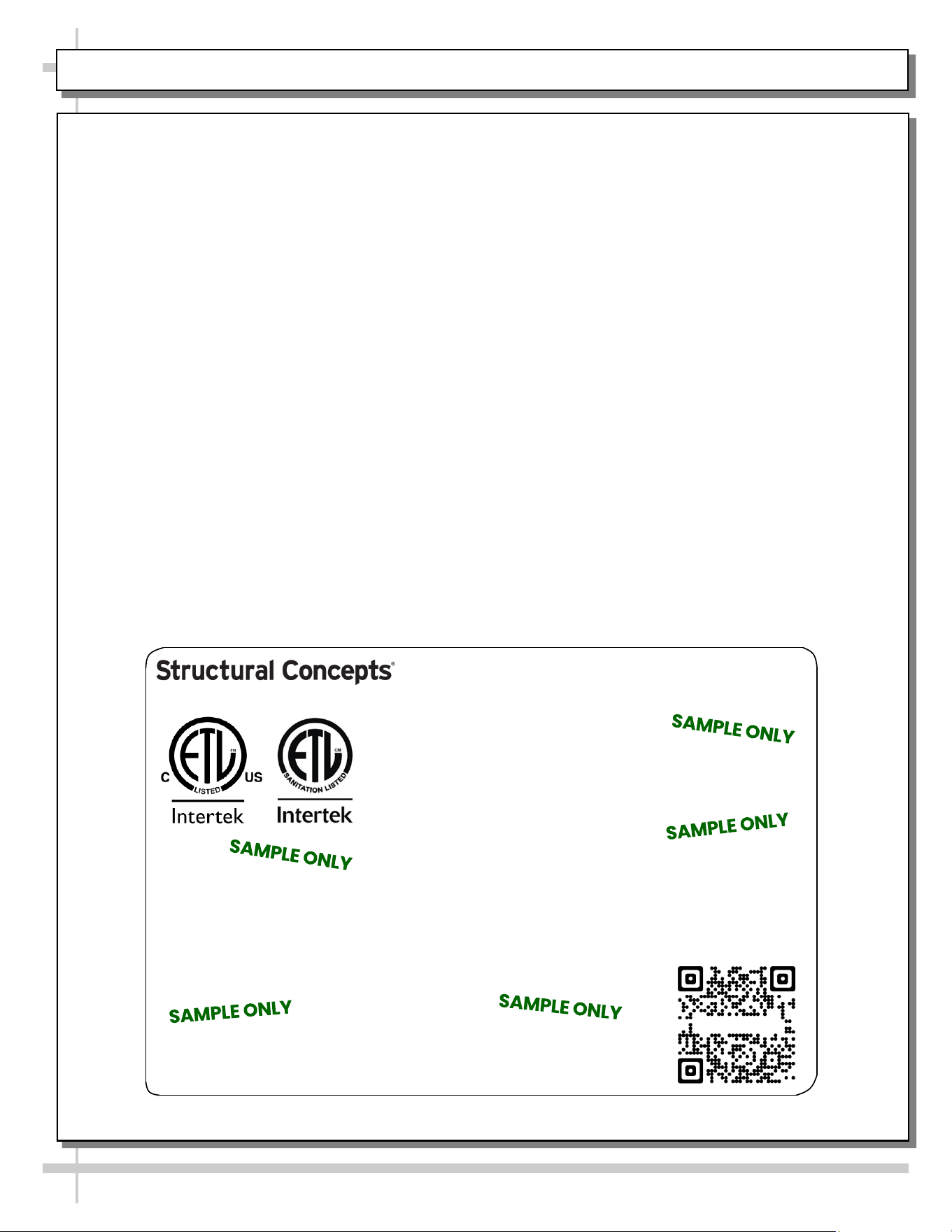
SERIAL LABEL LOCATION & INFO LISTED / TECH INFO & SERVICE / REFRIGERATED CASES ONLY
--- Sample Serial Label For Refrigerated Cases ---
MODEL NRS3648RXV-SAMPLE
SERIAL NO. 12345X30DZ098765
TYPE II DISPLAY REFRIGERATOR: THIS EQUIPMENT IS INTENDED FOR USE IN AN AREA
WHERE THE ENVIRONMENTAL CONDITIONS ARE CONTROLLED AND MAINTAINED SUCH
THAT THE AMBIENT TEMPERATURE DOES NOT EXCEED 80 °F (27 °C).
888 E. Porter Rd - Muskegon, MI 49441
3048256
Conforms to UL Std. 471
Conforms to NSF/ANSI Stds. 2 & 7
CERTIFIED TO CAN/CSA
STD C22.2 NO 120
ELECTRICAL RATING
REFRIGERANT
DESIGN PRESSURE
MINIMUM CIRCUIT AMPACITY
MAXIMUM OVERCURRENT
120/1/60 16 A
R513A AMOUNT 50 OZ
HIGH 186 LOW 88
20A
20A
Super Heat Temp 6-8 °F FOR PARTS AND SERVICE
Defrost 6 defrosts per day, 45 °F CALL 1-800-433-9490
Serial Label Location & Information Listed /
Technical Information & Service
• Serial labels are affixed at a wide range of places
(on the header, near thermostat, at case rear,
behind panels/toe-kicks, on electrical boxes, etc.).
• Serial labels contain electrical, temperature and
refrigeration information, as well as regulatory
standards to which the case conforms.
• Sample serial label shown below.
• For additional technical information and service, see
the TECHNICAL SERVICE page in this manual for
instructions on contacting Structural Concepts’
Technical Service Department.
Reveal
Harmony
Fusion
Impulse
Addenda
Blend
Grocerant
Oasis
Sample QR Code
SCAN FOR PRODUCT LITERATURE
STRUCTURAL CONCEPTS TECHNICAL SERVICE CONTACT INFORMATION & LIMITED WARRANTY
27
TECH SERVICE/WARRANTY CONTACT INFO:
1 (800) 433-9490 / EXTENSION 1
DAYS/HOURS AVAILABLE:
MONDAY - FRIDAY (CLOSED HOLIDAYS)
8:00 a.m. TO 5:00 p.m. EST
YOU MUST HAVE THE FOLLOWING INFO AVAILABLE
BEFORE CONTACTING STRUCTURAL CONCEPTS:
SERIAL NO. / MODEL NO. / STORE NO. / STORE
ADDRESS / DETAILS (PHOTOS, LEAK LOCATIONS,
DAMAGE, STORE’S AMBIENT CONDITIONS, ETC.)
To Access The Limited Warranty To Your
Case, Follow These Instructions:
> If Viewing This Document on Smart Phone,
Tablet or Computer, Select/Click On The QR
Code at Right.
> If Viewing This Document In Print (Hard
Copy), Scan The QR Code at Right With Your
Smart Phone or Tablet.