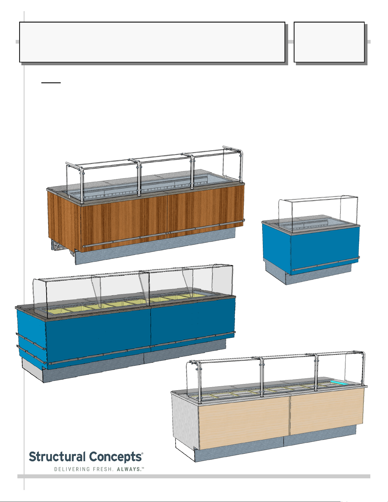
GROCERANT™ REMOTE SERVICE INLINE COLD WELL FOOD MERCHANDISERS WITH DROP-IN PANS
NOTE: UNITS MAY INCLUDE CERTAIN FEATURES OR OPTIONS LISTED BELOW:
REV G DATE: 05/17/2023
USER MANUALS\20-89548_GROCERANT_USER MANUAL_FB(L)S-(P)R_REF WELL_SVC_REM_UV-B GLASS_INLINE_CASE
FB9S-7R
> UV-BONDED GLASS UPPER (WITH OPTIONAL DESIGN
FOR ADJOINED CASES)
> CLEAR GLASS SNEEZE GUARDS WITH STAINLESS
STEEL POSTS
> REFRIGERATED INSULATED WELLS
> REFRIGERATED WELLS WITH “SHARED AIR” PLENUMS
(SEE “SHARED AIR” SECTION IN USER MANUAL FOR
SPECIFICS)
> REAR REFRIGERATED STORAGE VIA SLIDING DOORS,
HINGED DOOR OR DRAWERS
> OPEN/AMBIENT REAR STORAGE
> ADJUSTABLE SIDE SPLASH BRACKETS
> REMOVABLE FRONT PANEL (FOR ADJOINMENT
PURPOSES)
> GUSSETS AND TABS (FOR ADJOINMENT PURPOSES)
> REMOVABLE REAR PLATE (FOR ADJOINMENT
PURPOSES)
SCC P/N
20-89548
USER
MANUAL
GROCERANT
CAREFULLY FOLLOW THESE INSTRUCTIONS
Structural Concepts Corp. ∙ 888 E. Porter Rd ∙ Muskegon, MI 49441 Phone: 231.798.8888 Fax: 231.798.4960 ∙ www.structuralconcepts.com
FB10S-8R.8072
FB4S-3R
FB10S-8R.8018
2
TABLE OF CONTENTS
TABLE OF CONTENTS …...………………………………………………………………………….………...
OVERVIEW / CONDITION “TYPE” / COMPLIANCE / WARNINGS / PRECAUTIONS .…....................
CASE REMOVAL FROM SKID / POSITIONING / FORK LIFT / J-BAR or DOLLY .…..……..….…..….
ADJOINMENT GUIDE: LOWERING FRONT PANEL FOR END PANEL ADJOINMENT .....……..…....
ADJOINMENT GUIDE, CONT’D: REAR ADJOINMENT ACCESS (VIA COVER PLATE REMOVAL)..
ADJOINMENT GUIDE, CONT’D: BASE FRAME / GUSSET / BREAKOFF ADJOINMENT BRACKET
UV-BONDED GLASS ENCLOSURE DESIGN OPTIONS …………………………………………………..
SPLASH GUARD BRACKETS: INSERTION AT CASE FRONT / ADJUSTABILITY / SEALING TO
FLOOR ……………………………………………………………………………………………………
BASE RAILS / REMOVABLE FRONT AND REAR TOE-KICKS …………………………………………..
ELECTRICAL OVERVIEW: FIELD ACCESS / DRIVERS / FIELD SENSOR / T-STRIP …..……...........
ELECTRICAL OVERVIEW, CONT’D: THERMOMETERS ………………………………………………….
START-UP & OPERATION - REFRIGERATED UPPER SECTION …..…………………………………...
REFRIGERATED REAR SECTION WITH SLIDING DOORS ………………………………………………
REFRIGERATED REAR SECTION WITH DRAWERS ……………………………………………………..
REFRIGERATED REAR SECTION WITH HINGED DOOR ………………………………………………..
REAR REFRIGERATED “SHARED AIR” SECTION / SLIDING DOORS / THERMOMETERS ………..
CLEAR GLASS WITH STAINLESS STEEL POSTS …………...………………………………………...…
CLEANING SCHEDULE: DAILY “D” / WEEKLY “W”....……………………………………….…………...
ENGINEERED (SYNTHETIC) QUARTZ CARE AND MAINTENANCE …………………………………...
CLEANING SCHEDULE: STAINLESS STEEL ……………………………………………………………….
CLEANING SCHEDULE: DAILY / WEEKLY: DECK PANS / DIVIDERS / PRODUCT PANS / TUB .....
TROUBLESHOOTING (TO BE PERFORMED BY STORE PERSONNEL) ……………………………...
TROUBLESHOOTING (TO BE PERFORMED BY TRAINED SERVICE PROVIDERS ONLY) ………..
SERIAL LABEL LOCATION & INFORMATION LISTED / TECH INFO & SERVICE …………………...
TECHNICAL SERVICE CONTACT INFORMATION / WARRANTY INFORMATION …………………...
2
3-4
5
6
7
8
9
10
11
12
13
14
15
16
17
18
19
20
21
22
23
24
25
26
27
3
OVERVIEW
• These Structural Concepts Grocerant™ refrigerated service
cases are designed to merchandise product at 40 °F
(4.5 °C) or less.
• Product must be pre-chilled to 40 °F (4.5 °C) or less
before being placed in merchandiser.
• Cases should be installed and operated according to this
operating manual’s instructions to ensure proper
performance. Improper use will void warranty.
TYPE 1 vs. TYPE 2 CONDITIONS
This unit is designed for the display of products in ambient
store conditions where temperatures and humidity are
maintained within a specific range.
• Type 1 conditions: ambient conditions are to be 55%
max. humidity and 75 °F (24 °C) max. temperature.
• Type 2 conditions: ambient conditions are to be 55%
max. humidity and 80 °F (27 °C) max. temperature.
• If unsure if unit is Type 1 or 2, see tag next to serial label.
See SERIAL LABEL LOCATION & INFORMATION
LISTED / TECH INFO & SERVICE section in this manual
for sample serial labels).
COMPLIANCE
• Performance issues when in violation of applicable
NEC, federal, state and local electrical and plumbing
codes are not covered by warranty.
• See below compliance guideline.
WARNINGS
• This page contains important warnings to prevent injury or
death. Please read carefully!
PRECAUTIONS and WIRING DIAGRAMS
• See next page for PRECAUTIONS and WIRING
DIAGRAM information.
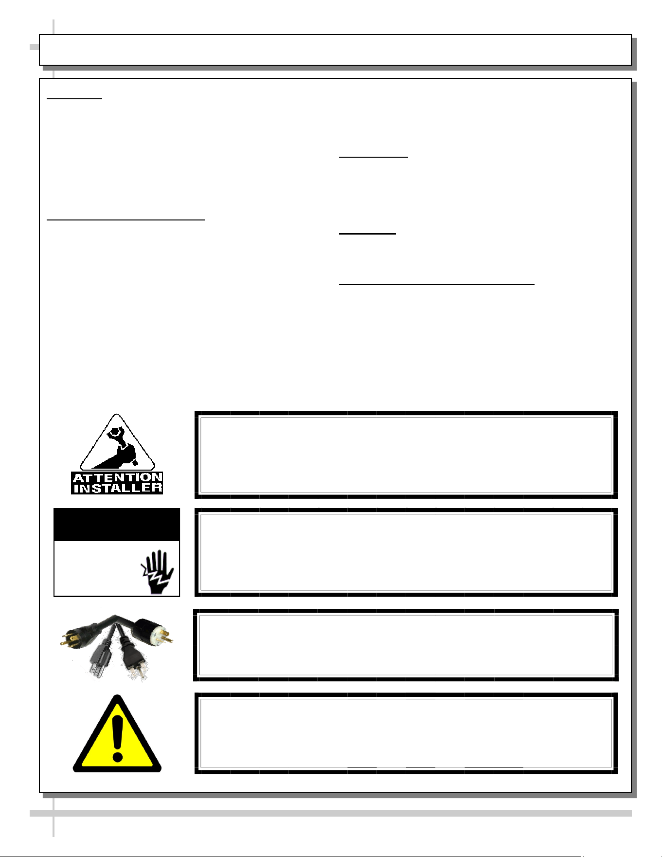
WARNING
Risk of electric shock. Disconnect power before servicing unit.
CAUTION! More than one source of electrical supply is
employed with units that have separate circuits.
Disconnect ALL ELECTRICAL SOURCES before servicing.
WARNING
ELECTRICAL
HAZARD
COMPLIANCE
This equipment MUST be installed in compliance with
all applicable NEC, federal, state and local
electrical and plumbing codes.
OVERVIEW / TYPE / COMPLIANCE / WARNINGS / PRECAUTIONS / CORDS / WIRING - PAGE 1 of 2
WARNING
This product can expose you to chemicals, including
Urethane (Ethyl Carbamate), which are known to the state of
California to cause cancer and birth defects or other reproductive
harm. For more information go to P65Warnings.ca.gov.
CAUTION! POWER CORD AND PLUG MAINTENANCE
Risk of electric shock. If cord or plug becomes damaged,
replace only with cord and plug of same type.
PRECAUTIONS
• Following are important precautions to prevent damage
to unit or merchandise. Read carefully!
• See previous page for specifics on OVERVIEW,
CONDITION TYPE, COMPLIANCE and WARNINGS.
WIRING DIAGRAM
• Each case has its own wiring diagram folded and in its
own packet. It may be placed near ballast box, field
wiring box, raceway cover, or other related location.
REFRIGERANT DISCLOSURE STATEMENT
• This equipment is prohibited from use in California with
any refrigerants on the “List of Prohibited Substances” for
that specific end-use, in accordance with California Code
of Regulations, title 17, section 95374.
• This disclosure statement has been reviewed and
approved by Structural Concepts and Structural Concepts
attests, under penalty of perjury, that these statements
are true and accurate.
WEIGHT LOADS ON GLASS / PREVENTING SAGGING
• Caution! To prevent sagging, do not exceed 5 LB (2.3 KG)
weight load per top glass section between stainless steel
posts (or supports).
OVERVIEW / TYPE / COMPLIANCE / WARNINGS / PRECAUTIONS / CORDS / WIRING - PAGE 2 of 2
4
CAUTION! POWER CORD AND PLUG MAINTENANCE
Risk of electric shock. If cord or plug becomes damaged,
replace only with cord and plug of same type.
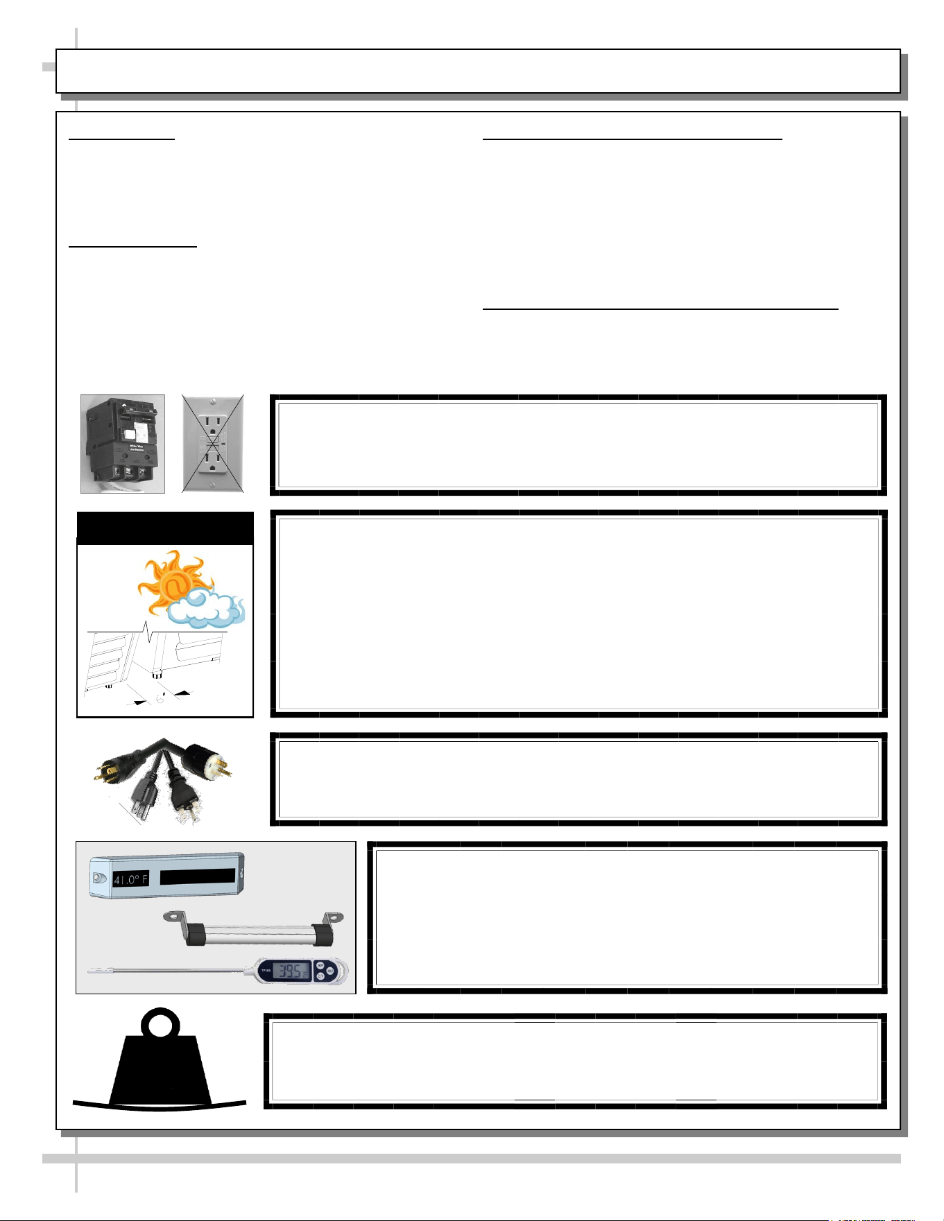
CAUTION! GFCI BREAKER REQUIREMENT
If N.E.C. (National Electric Code) or your local code
requires GFCI (Ground Fault Circuit Interrupter) protection,
you MUST use a GFCI breaker in lieu of a GFCI receptacle.
CAUTION! ADVERSE CONDITIONS / SPACING ISSUES
• Performance issues caused by adverse conditions are NOT warranted.
• To prevent damage to end panels due to condensation, apply industrial grade
silicone sealant and tightly join to opposite end panels. When not adjoining
cases, keep end panels at least 6” away from walls/structures. Rear panels
must also be kept at least 6” from walls and structures.
• Case must not be exposed to direct sunlight or any heat source.
• To maintain proper case temperature, keep case at least 15-feet from exterior
doors, overhead HVAC vents or any air curtain disruption.
• Self-contained case clearance: 6” min. air intake / 6” min. air discharge.
CAUTION
CAUTION! DO NOT RELY ON THERMOMETERS OR
THERMOSTATS FOR PRODUCT (FOOD) TEMPERATURES.
• Thermometers & thermostats reflect air temperatures ONLY.
• For ACTUAL product (food) temperatures, use a calibrated food
probe thermometers ONLY.
• For accurate readings, DO NOT use infrared food thermometers.
CAUTION!
To prevent sagging, do not exceed 5 LBS (2.3 KG) weight load
per top glass section (between posts and/or supports).
5
LBS
5
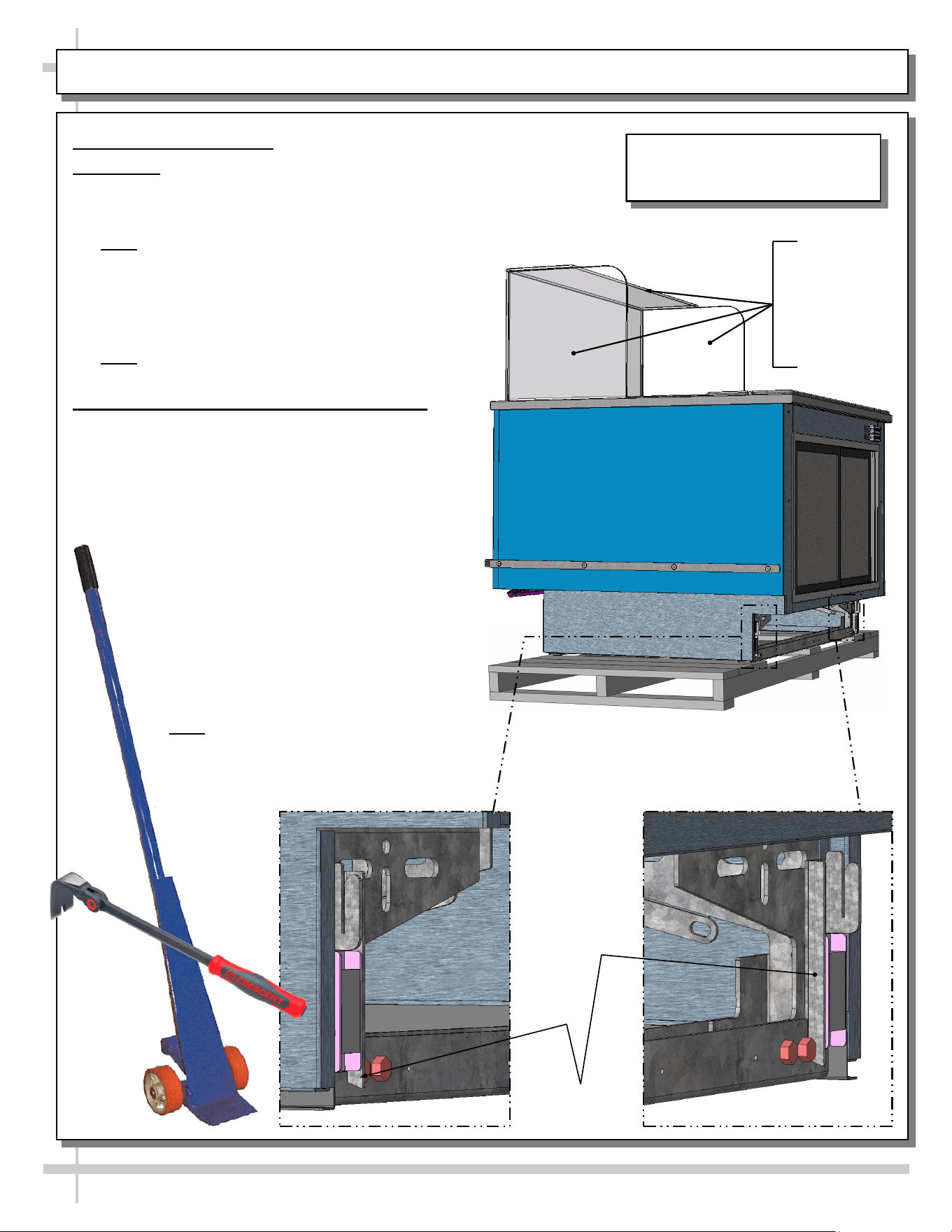
CASE REMOVAL FROM SKID / POSITIONING / FORK LIFT / J-BAR or DOLLY
J-Bar/Pry Bar
Lift Tabs
Remove Case From Skid
1. Fork Lift
• To lift case up for lift-truck forks to slide into position,
place J-bar, indexing flat pry bar or dolly under J-Bar
lift tabs (location shown below).
• Note: REAR lift tabs are extended beyond base
frame bolts (to allow greater access).
• Raise case up to allow forks to slide under rails.
• Insert forks under rails.
• Make certain case is well-supported on forks.
Move case to desired location. Lower in place.
• Note: Illustration shown may not reflect every
feature or option of your particular model.
2. J-Bar, Indexing Flat Pry Bar or Dolly Only
• Caution! Do not push or pull on glass while
moving case into position!
• With several people in position, carefully
slide frame support rail to edge of skid.
• Slide case off skid and lower frame
support to floor.
• Once the frame support rail rests on the
floor, have several people supporting
front of case while skid is slid out from
under case.
• After case is off skid, several people
may be required to slide into position.
• Or, depending upon case weight, use
J-Bar, dolly or indexing flat pry bar to
incrementally lift and rotate case into
desired position.
• Note: Illustrations shown may not
exactly reflect every feature or option of
your particular case.
Caution!
Do Not Push or
Pull on Glass
While Moving
Case Into
Position!
Indexing
Flat Pry Bar
J-Bar
Rear View of Model FB4S-3R Is
Shown. It May Not Reflect Every
Feature Or Option of Your Case.
6
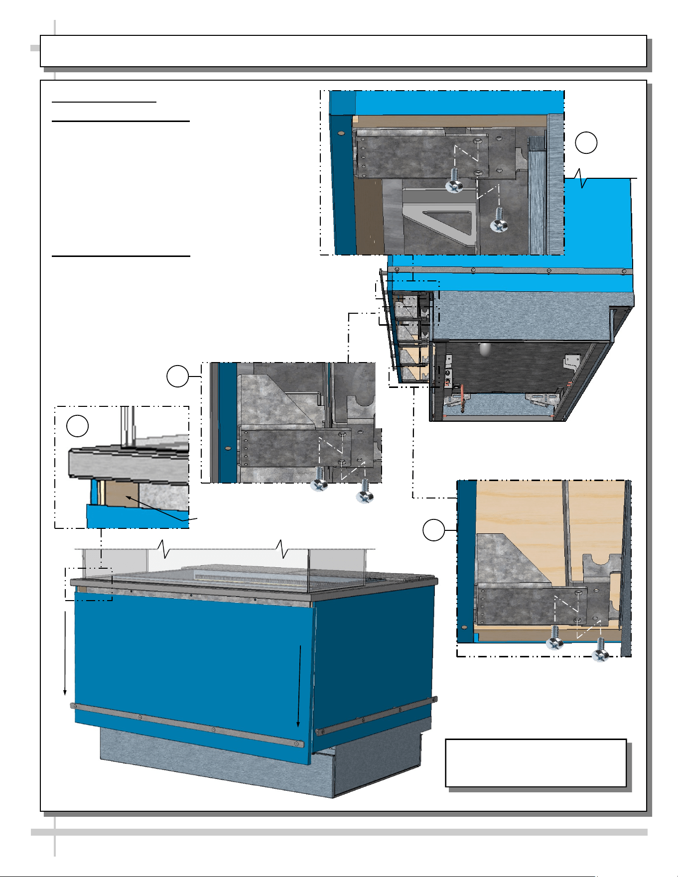
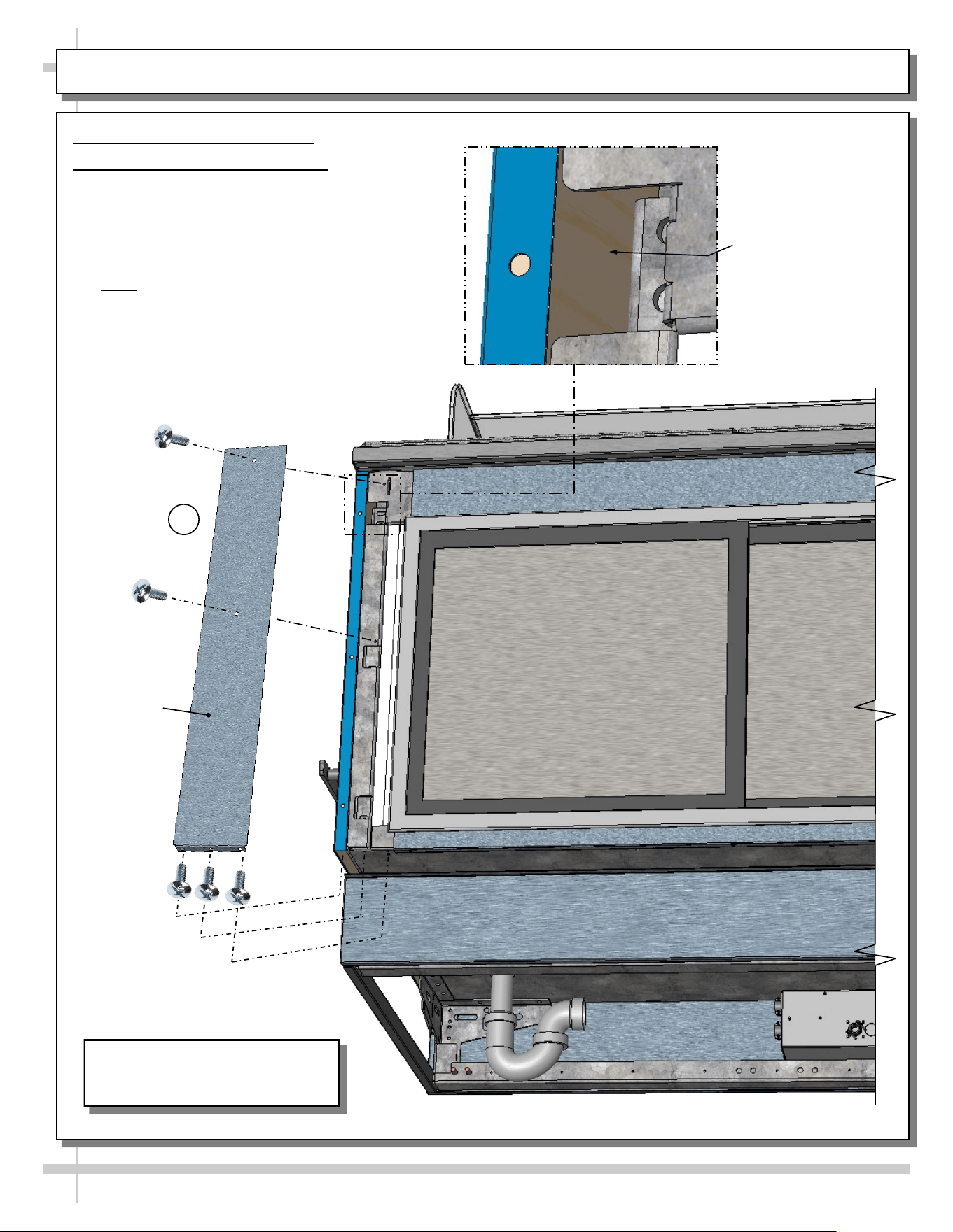
ADJOINMENT GUIDE: LOWERING FRONT PANEL FOR END PANEL ADJOINMENT
Adjoinment Guide
1. Lowering Front Panel
• Lowering front panel allows screws to be
inserted through inner end panels and into
adjacent cases.
• To do so, you must first remove two (2)
screws from brackets located at front
underside of case.
• Number of brackets vary depending upon
case length.
2. Adjoining End Panels
• Use wood screw to attach to adjacent case.
• After adjoinment screw has been attached, raise
front panel back up and reattach (2) screws in each
bracket.
• Drill bits and screws are provided in lineup kit.
• Number of brackets vary depending upon case
length.
*
Inner End Panel Adjoinment
Spot (At Both Ends) After
Front Panel Is Lowered
2
1
1
1
Screw Locations
(Remove To Lower The Front Panel)
Rear View of Model FB4S-3R Is
Shown. It May Not Reflect Every
Feature Or Option of Your Case.
7
ADJOINMENT GUIDE, CONT’D: REAR ADJOINMENT ACCESS (VIA COVER PLATE REMOVAL)
Adjoinment Guide, Continued
3. Rear Adjoinment Cover Plate
• Removal of rear adjoinment cover plate
allows access to inner end panels (at both
ends of case).
• Attach through end panel to adjacent case
end panel with wood screws.
• Note: Drill bits for pilot holes and wood
screws are included in adjoinment kit.
• Return rear adjoinment cover plate to case in
reverse order it was removed.
*
Apply Wood Screw
Through Inner End
Panel After Rear
Adjoinment Cover Plate
Has Been Removed
Rear View of Model FB4S-3R Is
Shown. It May Not Reflect Every
Feature Or Option of Your Case.
Rear
Adjoinment
Cover Plate
3
--- Rear View of Model FB4S-3R Is Shown Above ---
8
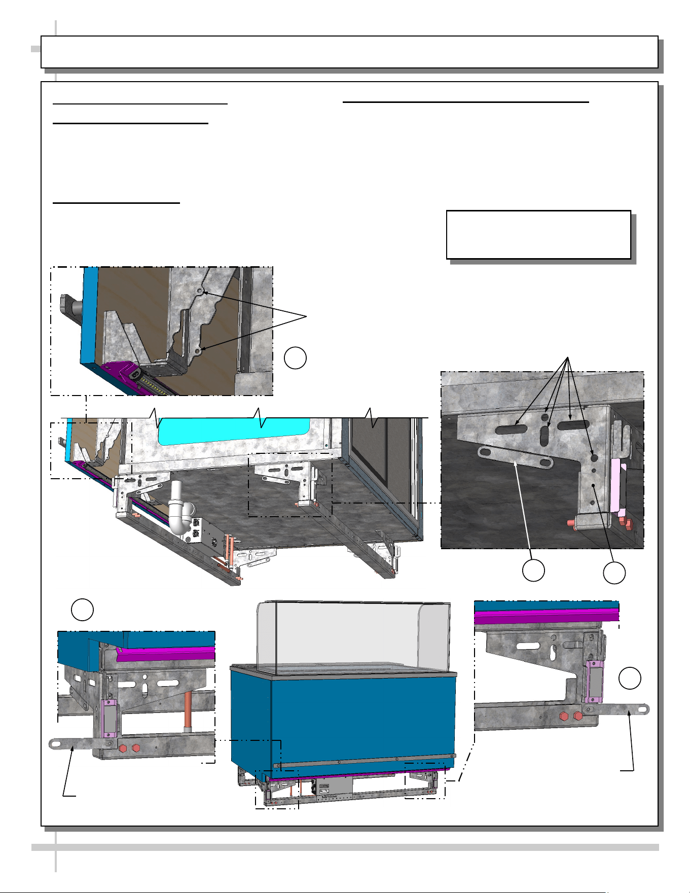
ADJOINMENT GUIDE, CONT’D: BASE FRAME / GUSSET / BREAKOFF ADJOINMENT BRACKET
Adjoinment Guide, Continued
4. Base Frame Adjoinment
• Base frames (at both ends of case) have many
holes and obrounds to adjoin to adjacent case
base frames.
• Use 5/16”ø bolt to adjoin base frames.
5. Gusset Adjoinment
• Gussets (at both ends) have holes for wood
screws to attach to adjacent case’s end panel.
• See illustration at top-left.
Gusset Holes For Wood
Screw Attachment To
Adjacent Case’s End Panel
Base Frame Holes For 5/16”ø
Bolt Adjoinment Into Adjacent
Case’s Base Frame
Breakoff Adjoinment
Bracket: Use
SCC-Supplied 1/4-20
Screws To Attach To
Adjacent Case.
4
5
6
6
6. Breakoff Adjoinment Bracket (Optional)
• An adjoinment bracket comes from the factory
attached to base frame.
• As an option, it may be broken off and attached to
the front base frames of adjoining cases.
• See illustrations below.
--- Case Front ---
Breakoff Adjoinment
Bracket (Shown Attached
To Front of Case)
6
Rear View of Model FB4S-3R Is
Shown. It May Not Reflect Every
Feature Or Option of Your Case.
9
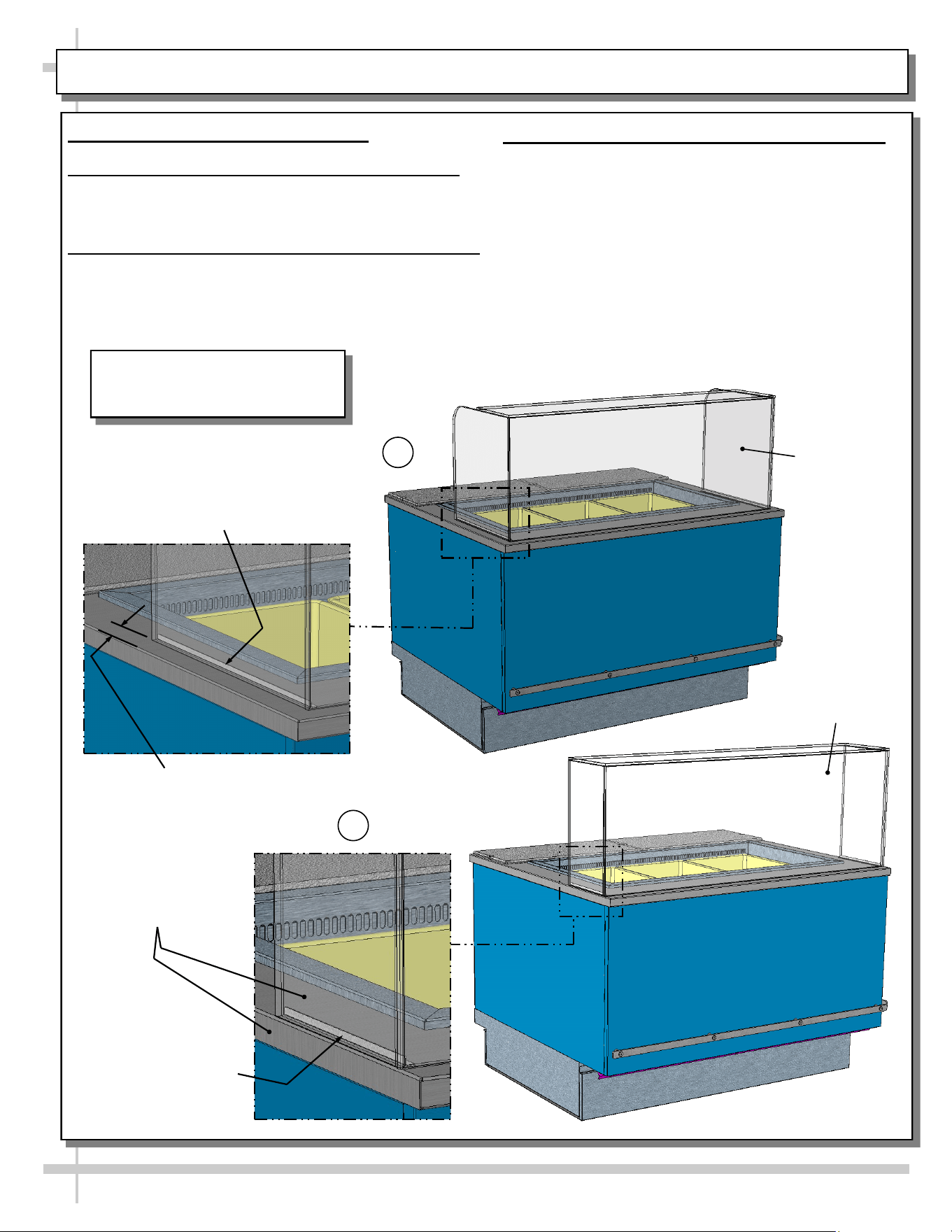
UV-BONDED GLASS ENCLOSURE DESIGN OPTIONS
UV-Bonded Glass Enclosure Options
1. Standard UV-Bonded Glass Enclosure Design
• Standard glass enclosures have a 1 1/2” space
between glass and work surface edge.
2. Continuous UV-Bonded Glass Enclosure Design
• Extended UV-bonded glass enclosures are flush to
work surface edge.
• This feature may be either at BOTH ends of case.
3. UV-Bonded Glass Installation Sheets/Guides
See documents included with shipment:
A. P/N 20-60789 UV-Bonded Glass Crate Removal
Sheet
B. P/N 20-76828 UV-Bonded Glass Alignment/
Placement Sheet
C. P/N 20-71700 UV-Bonded Glass Installation
Guide
D. P/N 20-76539 UV-Bonded Glass Installation
Guide (Spanish Version)
1 1/2” Space Between
Glass And Work Surface
Edge (At Both Ends)
Standard
UV-Bonded
Glass
Enclosure
Design
Continuous
UV-Bonded
Glass Enclosure
Design
Support Bracket (Glued
To Inner UV-Bonded
Glass At Factory)
--------------------
Attach To Work Surface
With Tape (From Factory)
Glass Is Flush To Work
Surface Edge
(At One or Both Ends)
2
1
Support Bracket (Glued To Inner
UV-Bonded Glass At Factory)
--------------------
Attach To Work Surface With
Tape (From Factory)
Rear View of Model FB4S-3R Is
Shown. It May Not Reflect Every
Feature Or Option of Your Case.
General Tub
Area
10
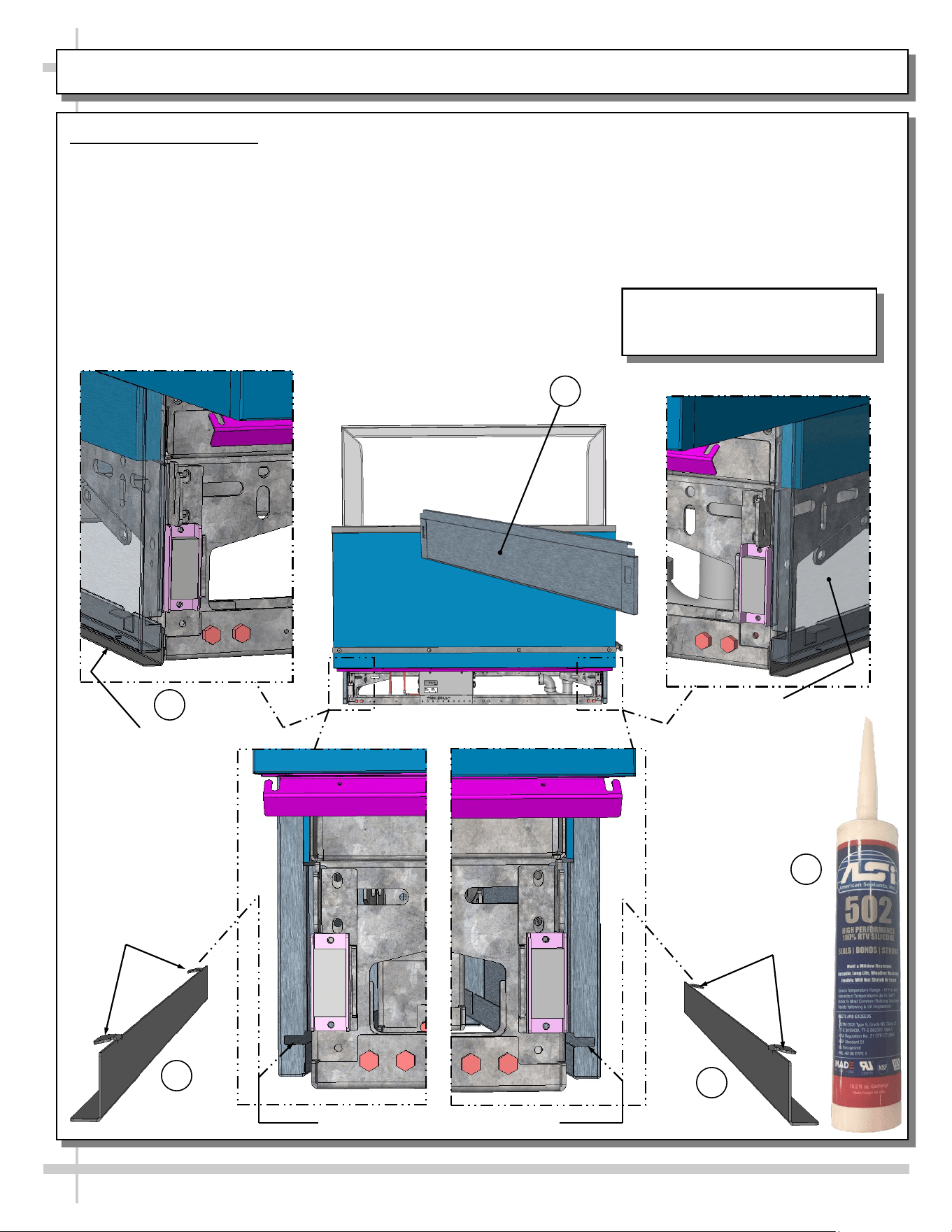
SPLASH GUARD BRACKETS: INSERTION AT CASE FRONT / ADJUSTABILITY / SEALING TO FLOOR
Case Front View
Shown Below
Splash Guard Bracket
Shown Inserted Into
Base End Panel And
Flush To Floor
Splash Guard Brackets
• The separately shipped splash guard brackets are
designed to prevent entry or leakage of liquid or
moisture to underside of case.
• Case must be properly positioned and frame
support rails shimmed before bracket placement.
• Follow these instructions for proper splash guard
placement.
1. Remove front toe-kick (slot/hook/magnet method).
2. Insert the separately shipped splash guard
brackets into the base end panel slots.
3. Slide splash guard brackets into base end panels
until tabs drop into panel slots. Splash guard
brackets will now self-adjust flush to floor.
4. Raise splash guards upward and apply a bead of
industrial grade silicone sealant to underside.
Press splash guards bracket firmly to floor.
>> Replace front toe-kick.
1
2
2
Base End Panel
(Shown Transparent)
With Splash Guard
Bracket Shown
Inserted And Flush
To Floor
3
Tabs
Tabs
4
Slots For Splash Guard Bracket Tabs
Rear View of Model FB4S-3R Is
Shown. It May Not Reflect Every
Feature Or Option of Your Case.
11
BASE FRAMES / REMOVABLE FRONT AND REAR TOE-KICKS
1. Base Frames
• Illustration below shows random case with base
frames at underside.
• Base frames must be shimmed.
• Shims will be provided with all cases.
• Note: After case is in position, it must be
sealed to floor to prevent entry or leakage of
liquid or moisture.
2. Removable Front and Rear Toe-Kicks
• Front and rear toe-kicks consist of slots that may
be lifted up and off case hooks (no screw removal)
and separated from magnets.
• Illustration below shows front toe-kicks being
removed.
• Return to case after accessing for cleaning or
service.
Front Toe-Kick Hook
and Magnet (No Screw
Removal Required)
Base Frames
Removable Front Toe-Kick
Shown Removed From Case
(And Reversed For Illustrative
Purposes Only)
J-Bar / Fork-Lift
Tab (Typ.)
Rear View of Model FB4S-3R Is
Shown. It May Not Reflect Every
Feature Or Option of Your Case.
12
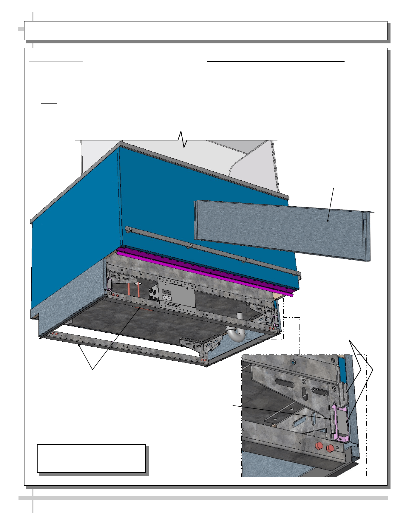
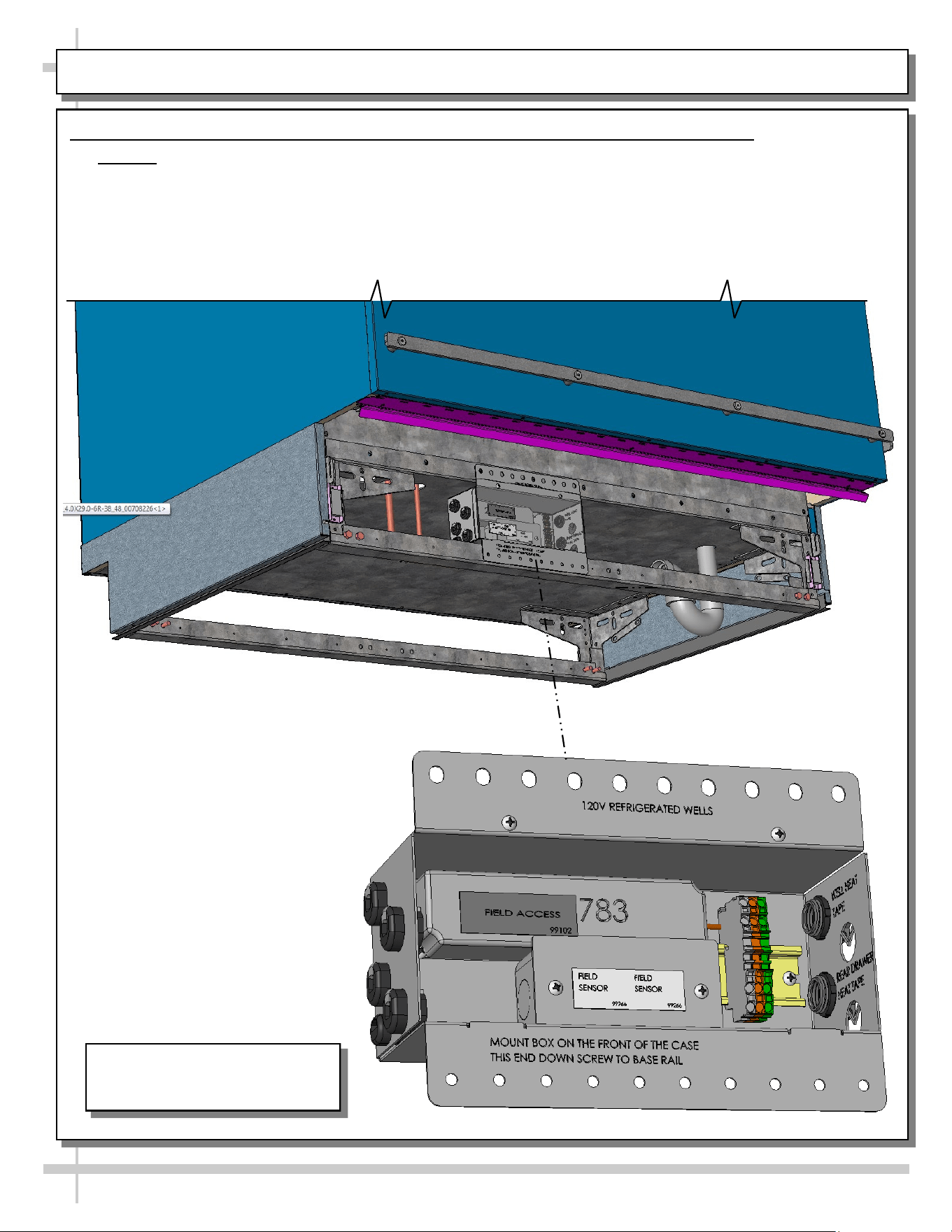
ELECTRICAL OVERVIEW: FIELD ACCESS / DRIVERS / FIELD SENSOR / T-STRIP
1. Electrical Overview: Field Access Box / Drivers / Field Sensor Box / Terminal Strip
• Caution! Only certified electricians are to perform electrical connectivity duties.
• Remove front panels (via hook/magnet method) to access field access box (see previous page).
• Remove screws at front of field access boxes allows access to drivers and other electrical components.
Rear View of Model FB4S-3R Is
Shown. It May Not Reflect Every
Feature Or Option of Your Case.
13
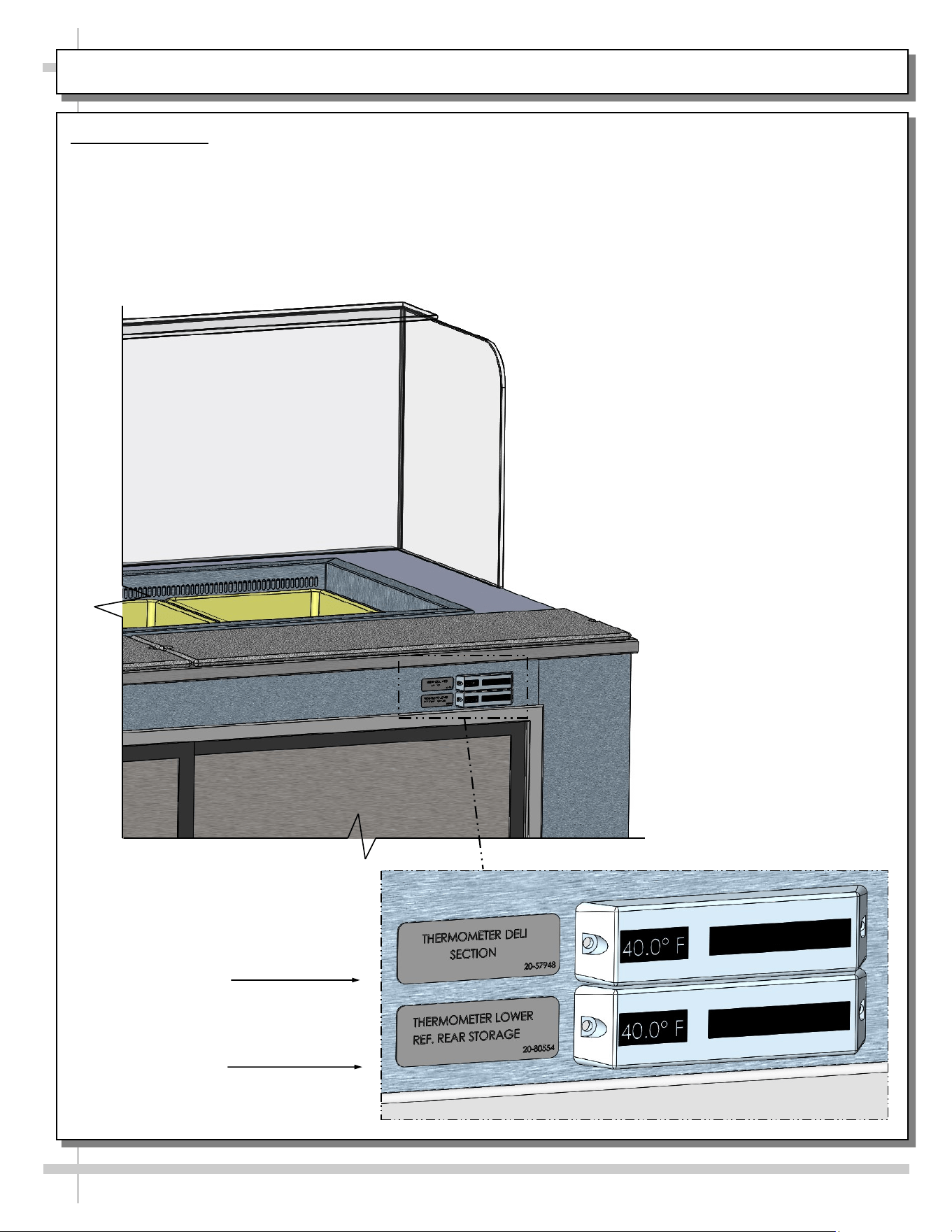
ELECTRICAL OVERVIEW, CONTINUED: THERMOMETERS
2. Thermometers
• Upper digital thermometer displays temperatures of the refrigerated upper section (with pans & dividers).
• Lower digital thermometer displays temperatures of lower refrigerated rear storage.
• Thermometer directly above refrigerated storage compartment measures case’s internal temperature.
• Thermometers are for monitoring internal air temperature only (not actual food temperature).
• Use probe thermometers to determine actual product temperatures.
Upper Thermometer
For Refrigerated
Wells (Deli) Section
Lower Thermometer
For Rear Refrigerated
Storage Section
TXV
14
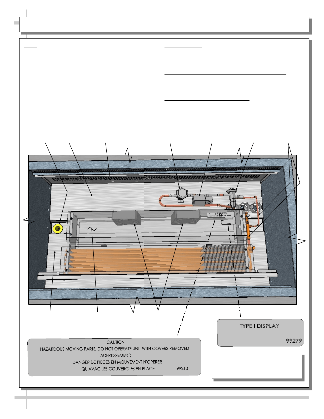
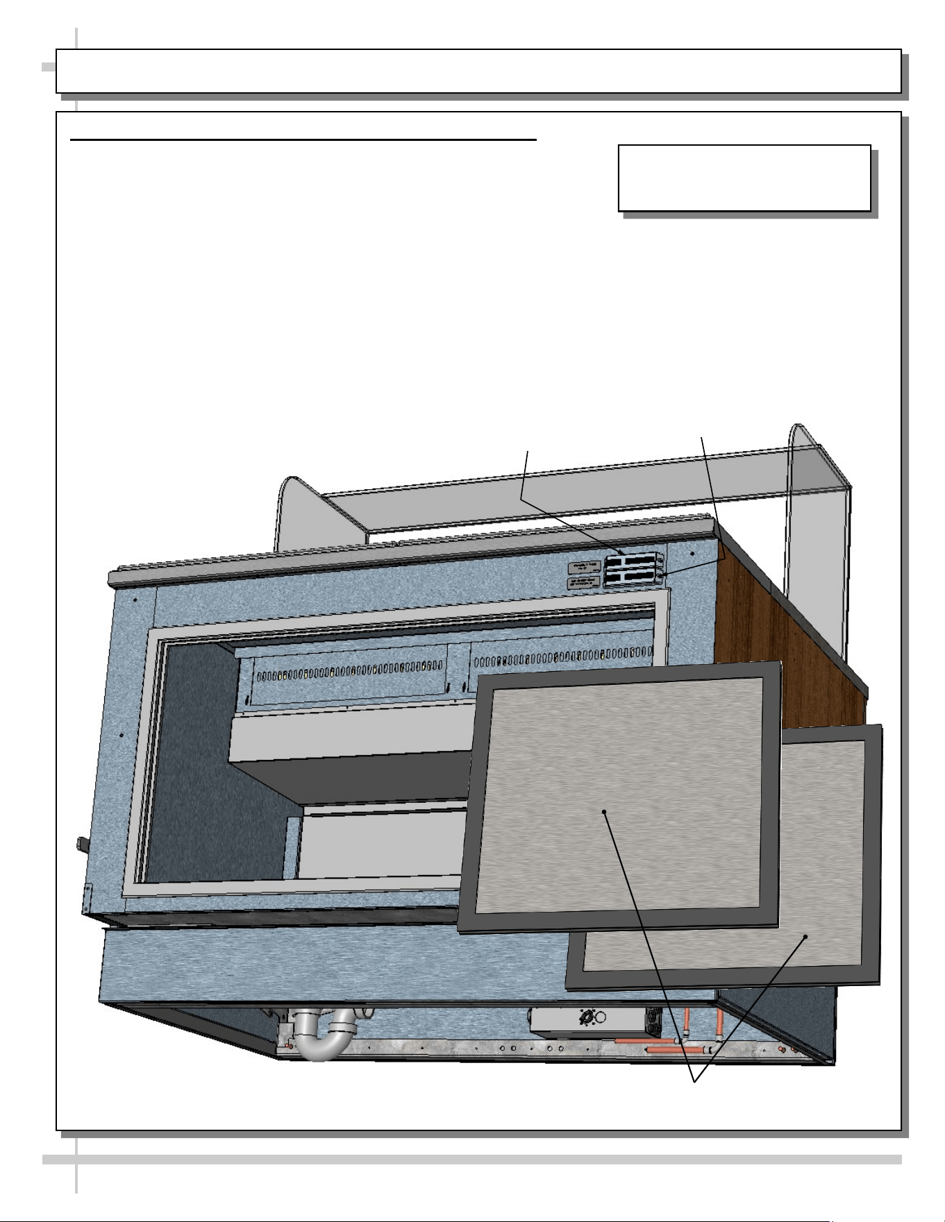
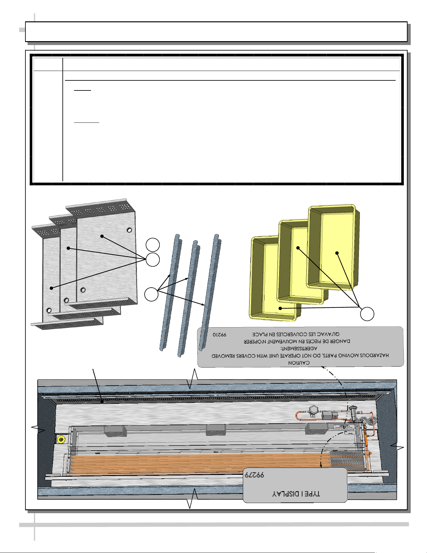
START-UP & OPERATION - REFRIGERATED UPPER SECTION
Note: Exact location of fans, refrigeration lines,
coil, shroud, valves and thermometer may vary
depending upon your case.
Merchandiser Start-Up and Operation
1. Powering Up Refrigerated Section
• Refrigeration upper section energize when
field-wired.
• Listen for fans to verify that unit is energized.
2. Axial Fans
• After removal of pans, axial fans are accessible.
• See transparent illustration below.
3. Refrigeration Lines, Solenoid Valve, TXV,
Shutoff Valve, Etc.
• See illustration below for locations.
4. Cleaning Refrigeration Area
• Refrigeration area must be cleaned regularly.
• See cleaning schedule in this manual for specifics.
Refrigeration
Lines
Shutoff Valve
Axial Fans
(Typ.)
Drain
Evaporator Fan Shroud
(Shown Transparent)
Solenoid Valve
Inner Perforated
Panel (Typ.)
Tub
Tub
*
**
Note: Illustration Shown May Not
Reflect Every Feature Or Option
of Your Particular Case.
15
REFRIGERATED REAR SECTION WITH SLIDING DOORS
Upper Thermometer
For Refrigerated
Wells (Deli) Section
Lower Thermometer
For Rear Refrigerated
Storage Section
Rear Refrigeration Section With Removable Sliding Doors
• Sliding doors are removable for cleaning or service.
• See illustration below.
Rear Sliding Doors (Removed For
Illustrative Purposes)
Rear View of Model FB4S-3R Is
Shown. It May Not Reflect Every
Feature Or Option of Your Case.
16
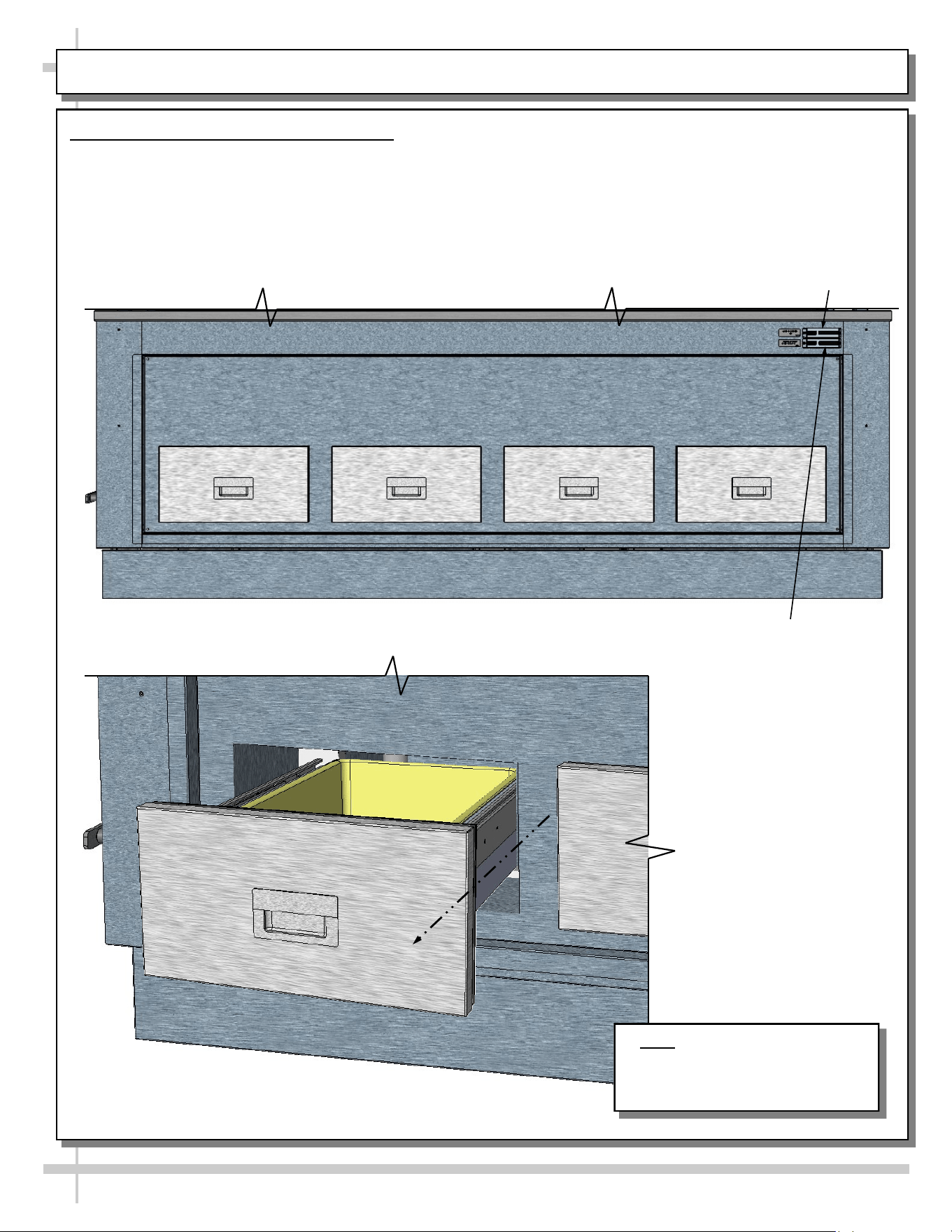
REFRIGERATED REAR SECTION WITH DRAWERS
Refrigerated Rear Section With Drawers
• Rear drawers are able to be slid out and/or removed for cleaning.
• See GENERAL CLEANING SCHEDULE: DAILY “D” / WEEKLY “W” for cleaning instructions.
Note: Random Model Shown.
Illustration Shown May Not
Reflect Every Feature Or Option
Of Your Particular Case.
--- Rear View of Random Case ---
--- Rear Left View of Random Case ---
Upper Thermometer
For Refrigerated
Wells (Deli) Section
Lower Thermometer
For Refrigerated Rear
Section With Drawers
17
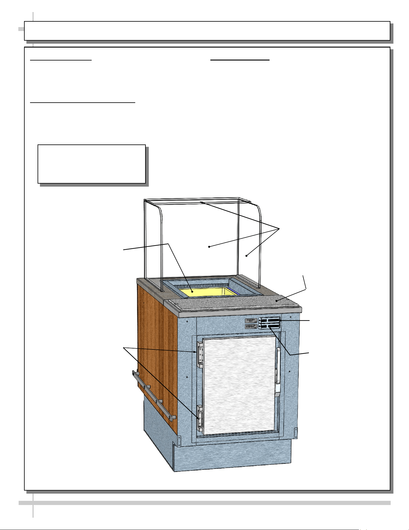
REFRIGERATED REAR SECTION WITH HINGED DOOR
1. General Layout
• Refrigerated wells, compartment and drawer,
sneeze guard, Sanalite® rear ledge, drain valve,
thermometers, etc., are shown below.
2. Cleaning Refrigeration Area
• Refrigeration area must be cleaned regularly.
• See cleaning schedule in manual for specifics.
3. Thermometers
• Upper digital thermometer displays temperatures
of the refrigerated upper section (with pans and
dividers).
• Lower digital thermometer displays temperatures
of the rear refrigerated section (either behind
sliding doors or hinged door).
• Thermometers are for monitoring internal air
temperature only (not actual food temperature).
• Use probe thermometers to determine actual
product temperatures.
• See illustration below for general locations.
Upper Thermometer
For Refrigerated
Wells Section
Rear Hinged Door To
Refrigerated Section
Refrigerated
Well
Sanalite® Rear
Ledge (Typ.)
Glass Sneeze
Guard (Typ.)
Lower Thermometer
For Rear Refrigerated
Section (Door)
--- Model FB2S-1R Shown Above ---
Model FB2S-1R Is Shown In This
Illustration. It May Not Reflect
Every Feature Or Option of
Your Particular Case.
18
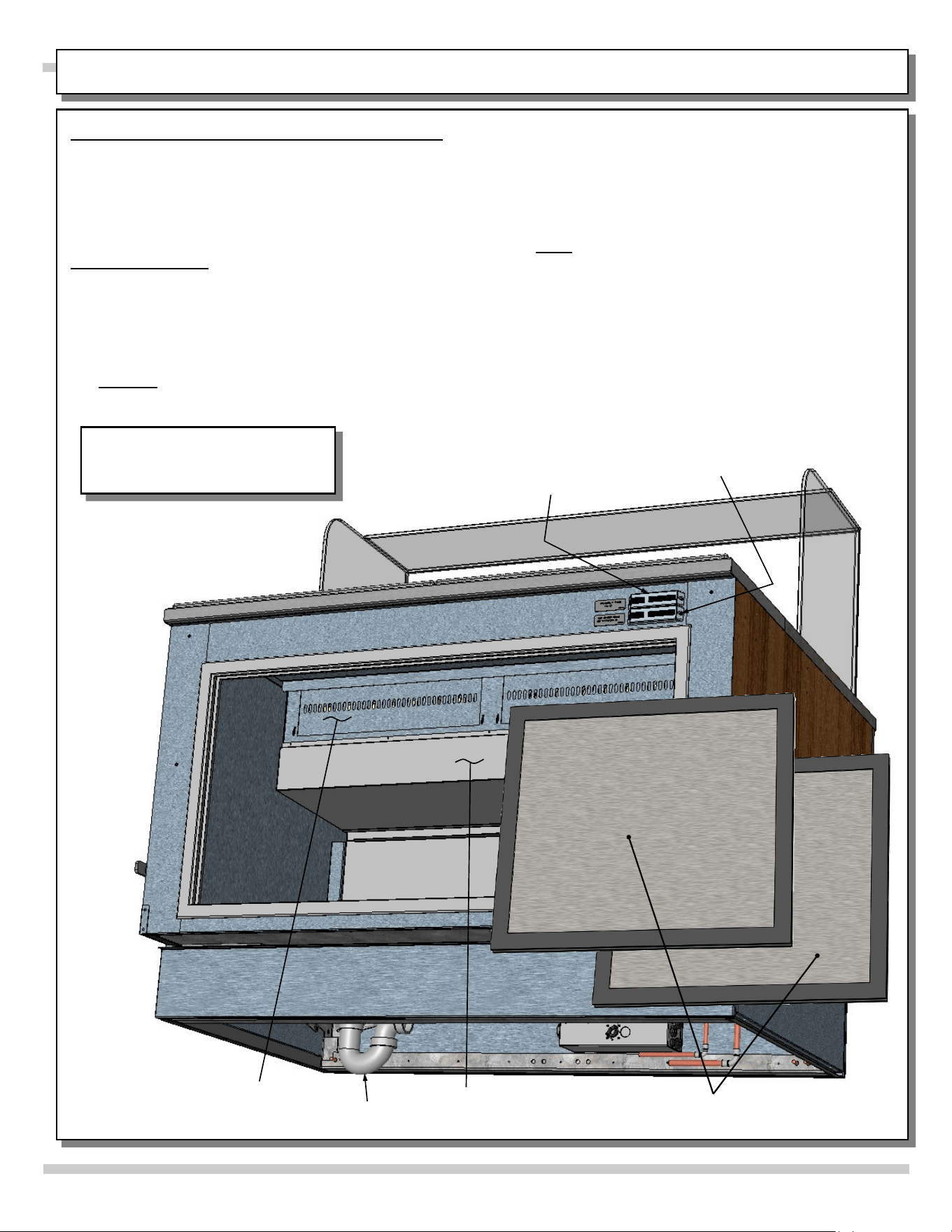
REAR REFRIGERATED “SHARED AIR” SECTION / SLIDING DOORS / THERMOMETERS
• Thermometers & thermostats reflect air
temperatures ONLY.
• For ACTUAL product (food) temperatures,
place probe directly in food product. Do not
solely rely on air temperature on thermometer
for accurate product temperature
• Note: Should food temperatures significantly
vary from acceptable range, contact SCC
Technical Service. See SCC TECHNICAL
SERVICE CONTACT INFORMATION section
of this manual for specifics.
• See illustration below.
1. Rear Refrigerated Section - With Shared Air
• Certain units have rear refrigerated section that
“shares air” with upper tub area.
• Refrigerated air flows through upper perforated
panel into lower/rear storage refrigerated section.
• See illustrations below.
2. Thermometers
• Upper thermometer reflects temperature of upper
refrigerated section.
• Lower thermometer reflects temperature of lower
refrigerated rear storage area.
• Thermometer reflects air temperature only.
• Caution: Do not rely on thermometer for actual
product (food) temperatures.
Upper Thermometer
For Refrigerated Wells
(Deli) Section
Lower Thermometer
For Rear Refrigerated
Storage Section
Rear Sliding Doors (Removed
For Illustrative Purposes)
P-Trap
Upper Perforated
Panel From
Inside Tub (Typ.)
Tub Housing
Rear View of Model FB4S-3R Is
Shown. It May Not Reflect Every
Feature Or Option of Your Case.
19
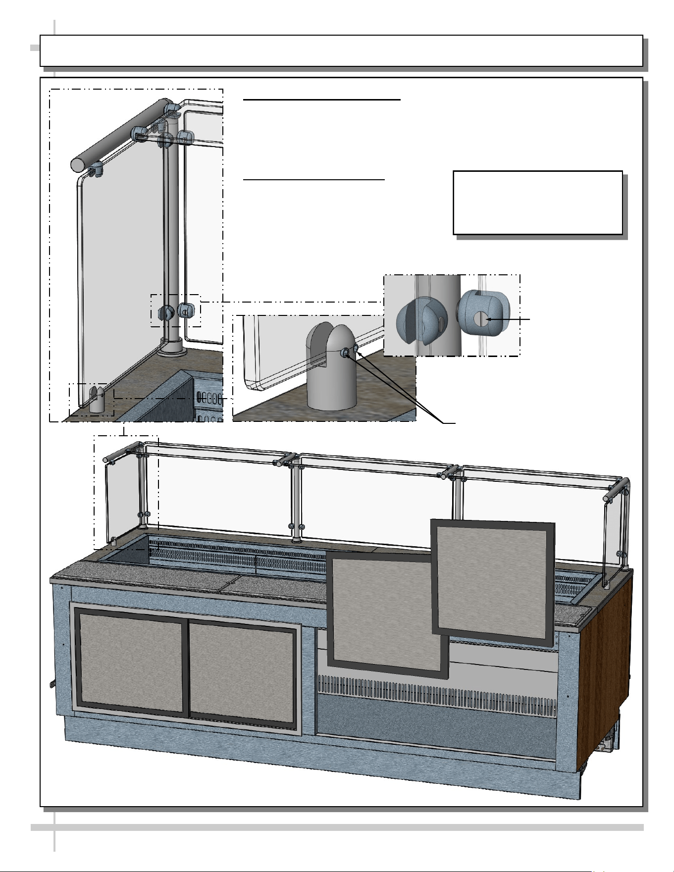
CLEAR GLASS WITH STAINLESS STEEL POSTS
1. General Design and Care
• Certain models will have stainless steel posts with clear glass
rather than UV-bonded glass.
• Caution! Do not push or pull on stainless steel posts while
moving case into position!
2. Glass Retaining Clips
• Glass retaining clips use either
Allen® screws or flat head
screws to hold glass in place.
• See illustration below.
Model FB9S-7R Is Shown In
This Illustration. It May Not
Reflect Every Feature Or
Option of Your Particular Case.
Glass Retaining Clip From
Countertop With Allen® Screws
Glass Retaining Clip
From Posts With
Flat Head Screws
20
CLEANING SCHEDULE: DAILY “D” / WEEKLY “W”
Area D W Task
Case
Exterior
X Wood / Laminate/ Painted Surfaces, etc.: Clean with a warm soap and water
solution and soft cloth. Never use wire cloth or abrasive cleaners on case.
X Sanalite® Cutting Board: Sanalite® cutting boards require very little
maintenance. Use a clean cloth to thoroughly wipe entire Sanalite® surface
with hot water and soap solution on a regular basis. Rinse with a spray bottle
of clean water. Pat dry with clean cloth or paper towel.
X Glass Sneeze Guard (Front/Sides/Top): Clean with a household or
commercial glass cleaner.
X Stainless Steel Surfaces: See CLEANING SCHEDULE: STAINLESS
STEEL - TO BE PERFORMED BY STORE PERSONNEL section in this
manual for cleaning and care instructions.
X Quartz Work Surfaces: See
• ENGINEERED (SYNTHETIC) QUARTZ CARE AND MAINTENANCE in this
User Manual.
Case
Interior
X Refrigerated Prep Area (Pan, Pan Covers and Pan Dividers, Decking, etc.):
See CLEANING SCHEDULE: DAILY / WEEKLY: DECK PANS / DIVIDERS /
PRODUCT PANS / TUB section in this operating manual for cleaning specifics.
X Refrigerated Rear Drawers or Doors: Wipe down with a warm soap and water
solution and soft cloth. Dry with soft cloth or paper towel.
X Rear Section (Accessible via Sliding or Hinged Doors or Drawers): Wipe
down with a warm soap and water solution and soft cloth. Dry with soft cloth or
paper towel.
X Under Case Cleaning: Remove front (or rear) lower panels. Use vacuum or
broom to clean flooring under case. Do not allow broom to create dust in store!
X Refrigeration Prep Area (Tub, Trough, Drain, Components, Perforated
Plenums, etc.):
• See CLEANING SCHEDULE - DAILY / WEEKLY: PANS / DIVIDERS /
DECK / PERFORATED PLENUMS / TUB section in this manual for
cleaning specifics.
21
ENGINEERED (SYNTHETIC) QUARTZ CARE AND MAINTENANCE
Engineered
Quartz
Overview
Engineered (Synthetic) Quartz Overview:
• Engineered (synthetic) quartz is a ‘man-made’ product. It is sometimes called “engineered stone.” It is made from
crushed quartz particles bonded with polyester, styrene, resin, pigments and tert-butyl peroxybenzoate.
• It is non-porous, mold and mildew-resistant, and impervious to odor-causing bacteria.
• Slabs are specifically sized. Engineered quartz contains a maximum of 94% mineral quartz (though percentages
vary). Engineered quartz is extremely resistant to damaging chemicals.
• There are many engineered (synthetic) quartz brands. These include Caesarstone, Cambria, Compac, Corian, Daltile
ONE, Granite HanStone, Transformations, Kowalski, LG Hausys, LG Viatera, Lunastone, Marble.com, MSI Q, Okite,
Pental, Polarstone, Pompeii, Samsung, Sensa, Silestone, Stone Italiana, Vadara, Vena & Vicostone.
Routine
Care
For Daily, Routine Care and Cleaning:
Engineered (synthetic) quartz require very little maintenance. Simply wipe the surface with neutral pH balanced
household detergent and warm water solution with soft sponge or microfiber cloth to maintain its shine.
• To prevent fading, keep from harsh, direct sunlight for long periods of time.
• General cleaners: use neutral pH balanced household detergent and warm water (4 cups of water/1 teaspoon of
detergent). Or isopropyl alcohol (aka rubbing alcohol). Or use any general, all-purpose cleaner, glass cleaner or Pine
Sol. Or use Clorox Wet Wipes (as they contain no bleach or and are soft). After cleaning, thoroughly rinse with water
and dry with clean cloth to prevent water spots from forming.
• Specifically designed cleaners for manufactured quartz: Black Diamond Stoneworks Granite Counter Cleaner,
Caldrea Countertop Spray, Clark’s Natural Stone Spray Cleaner, Granite Gold, Simple Green, Park & Bailey Granite
& Stone Cleaner, Seventh Generation Granite & Stone Cleaner, Stone Care Quartz Clean & Shine, Stone Pro Quartz
Countertop Cleaner, Weiman Quartz Countertop Cleaner and Polish.
Difficult
Spills
For Difficult Spills, Stains and Spots:
• Thoroughly clean with warm water and neutral pH detergent (mixture detailed above) before pursuing next steps.
• Clean up high staining liquids such as coffee, tea, fruit juice, lemon juice, vinegar, wine and tomato juice right away.
Use warm water and neutral pH detergent to do so. After cleaning, thoroughly rinse with water and dry.
• For residues that harden as they dry (food, gum, nail polish, and paint), place wet cloth or paper towel over residue
for 10 minutes (to soften its properties); then gently scrape off residue by using a plastic putty knife or plastic scraper;
avoid metal blades or scrapers if possible; then clean using warm water and soap. If you must use metal razor blade
or scraper, remove gray marks with soap and water. Thoroughly rinse with water and dry to prevent water spots.
• Difficult spots may need to be treated with solutions/chemicals BEYOND warm water and neutral pH detergents: A.
Water/white vinegar mixture: 2 cups of water with 1 tablespoon of white vinegar in spray bottle; spray surface; allow
solution to sit for 2 minutes; wipe off with soft cloth or sponge. B. Soft Scrub Liquid Gel: Apply gel to cloth or sponge
(not directly to quartz surface); wipe the area in a circular motion; repeat until spot is removed. C. Goo Gone
adhesive remover (for sticky residue). Thoroughly rinse the surface with water and wipe dry to prevent water spots.
• Water stain removal: 1 part vinegar + 3 parts baking soda in warm water. Dip cloth in mixture and thoroughly soak
stain. Leave for 5-10 minutes; then scrub area with soft brush. Rinse with water and dry with clean cloth.
Extreme
Heat
Protection
Extreme Heat Protection:
• Engineered quartz is extremely resistant to heat, and can withstand moderately high temperatures for brief periods of
time without being damaged.
• Engineered quartz CAN BE damaged by sudden and extreme temperature changes; thus, use a trivet or a hot pad to
protect its surface from hot pans, hot dishes or small appliances that may reach high temperatures.
Chemicals
To
Avoid
Chemicals To Avoid:
• Nail polish remover (acetone), oil soaps, and furniture cleaners or paint strippers that contain trichloroethane or
methylene chloride.
• Chemicals with an alkaline level of pH >10 (oven cleaners, chloring bleach, lacquer thinner, ammonia, tub and tile
cleaner, borax, etc.)
• Chlorinated solvents (trichloroethylene or methylene chloride)
• Concentrated acids (hydrocyanic acid, hydrofluoric acid, hydrochloric acid, sulfuric acid, nitric acid or CLR)
Caution must be used for the following products on engineered quartz surfaces:
• Avoid using products containing oils or powders as may leave a residue.
• Avoid abrasive scrubs/cleaners (such as Ajax, Comet, Scotch-Brite or oven cleaner) as it dull or discolor the finish.
Common stains like coffee, food, makeup, permanent markers, etc.:
• Apply the appropriate cleaner with a paper towel and wipe. If necessary, soak with paper towels from 3-10 minutes.
• Scrub the area with a non-abrasive cloth or sponge. Rinse and dry thoroughly.
Preventing
Scratches
Scratch Deterrence: Engineered quartz surfaces are scratch RESISTANT. However, they CAN be scratched or marred
by certain utensils or cleaning materials.
• Use a cutting board to avoid damaging the quartz surface and knives.
• Never use abrasive scouring pads, steel wool soap pads, Brillo® pads or “Magic Erasers.
22
STAINLESS STEEL SURFACE CARE & MAINTENANCE
Stainless Steel Surface Care & Maintenance
General Stainless Steel Surface Cleaning (To Be Performed As Often As Needed):
• Certain grades of stainless steel are more prone to corrosion than others.
• Stainless steel can be exposed to many contaminants, which if left untreated can cause stains and
rust.
• Stainless steel requires a specific cleaning procedure to maintain its sheen and remain rust-free.
• Wash with a solution of liquid dishwashing detergent and hot water.
• Rinse with pure hot water from spray bottle. Wipe with clean sponge. This will remove soap residue
that can lodge in stainless steel’s microscopic grooves, causing rust.
• Dry with clean, soft cloth or paper towel.
• Caution! To prevent rust, you MUST rinse with pure hot water from a spray bottle while wiping with
clean sponge after EACH cleaning.
• Caution! Never clean with scouring powder or steel wool as they mar, scratch and/or erode the surface
of stainless steel. When surface properties of stainless steel have been compromised, rust may form.
Brightening:
• Method 1: Brighten by polishing with a soft cloth or sponge with a solution of one part vinegar to 2 parts
water in a spray bottle.
• Method 2: Sprinkle baking soda on sponge and rub gently with soft cloth or sponge.
• Caution! To prevent rust, you MUST rinse with pure hot water from a spray bottle while wiping with
clean sponge after EACH cleaning.
• Dry with clean, soft cloth or paper towel.
Removing Streaks or Stains:
• Method 1: Place two teaspoons of rubbing alcohol on a microfiber cloth or pad. Rub the cloth along the
grain of the appliance until the entire area has been wiped. The rubbing alcohol will air dry itself.
• Method 2: Dip soft cloth or sponge in club soda and rub gently over area of concern.
• Caution! To prevent rust, you MUST rinse with pure hot water from a spray bottle while wiping with
clean sponge after EACH cleaning.
• Dry with clean, soft cloth or paper towel.
Polishing:
• Place a dab of olive oil onto clean soft cloth. Spread over area until a light sheen is observed. Use
pressure to “work the oil” into the small grooves in the surface. Apply firm, steady pressure using small
circular motions.
> Dry buff: Remove excess oil with clean cloth or paper towel using small circular motions.
> Wet buff: Use an ounce of white vinegar with clean cloth or paper towel using small circular motions.
> Continue wiping until oily finish has been removed.
• Caution! To prevent rust, you MUST rinse with pure hot water from a spray bottle while wiping with
clean sponge after EACH cleaning.
• Dry with clean, soft cloth or paper towel.
Removing Rust:
• If rust has begun to form, there are a variety of products that can treat it.
• Among these are CLR® (calcium, lime and rust remover) and Chemetall Oakite 33 (rust, oxides and
scale remover).
• Caution! To prevent food contamination, personal injury or further corrosion, carefully
observe and follow the rust-removing product’s precautions and instructions.
23
CLEANING SCHEDULE: DAILY / WEEKLY: DECK PANS / DIVIDERS / PRODUCT PANS / TUB
AREA INSTRUCTIONS
Deck
Pan /
Tub
Area
Follow These Steps To Clean Product Pans, Dividers, Perforated Plenums, Deck Pans, Etc.
1. Daily: Remove product pans and dividers and submerse them in warm, soapy water. Rinse.
Wipe down deck pans with warm, soapy water and cloth; rinse with spray bottle containing
clean water; dry. Wipe down deck pans (including perforated deck pan sides) with warm, soapy
water solution and clean cloth; rinse; dry. Return dividers and product pans to case.
2. Weekly: Trained Service Personnel Only - Disconnect Power To Case! After removing
product pans & dividers, remove deck pans (finger holes provided for easy removal).
Submerse all components in warm water, and clean with mild soap solution and soft cloth. Use
soft-bristled brush on hardened residue. Dry thoroughly. While components are removed from
case, wipe down tub, sides, components, trough and drain with warm, soapy water solution
and cloth. Rinse with spray bottle of clean water. Caution! Do not spray water into axial fans!
Dry with clean cloth or paper towel. Return all components to case in reverse order they were
removed.
1
Deck Pans (Typ.)
2
Dividers (Typ.)
Product Pans (Typ.)
1
1
Perforated Plenum (Typ.)
24
TROUBLESHOOTING (TO BE PERFORMED BY STORE PERSONNEL)
CONDITION TROUBLESHOOTING
Case Is Not Level See FRAME SUPPORT RAILS / REMOVABLE FRONT AND REAR
TOE-KICKS section in this manual for illustrations and instructions.
Water Is On The Floor Call service provider.
Fan Emits Excessive Noise Call service provider.
Case is Not Holding Proper
Temperature
If a large amount of warm product was added to the case, it will take time
for the temperature to adjust. Product must be pre-chilled before placing
in case.
Check that the case is not in the sun or near a heat or air-conditioning
vent. See OVERVIEW / TECHNICAL INFORMATION / WARNINGS
section in this manual for specifics.
If case is located near front doors, temperature fluctuation can hinder
unit’s ability to maintain temperature.
LED Lights (Optional) Are
Not Working
Check that light switch (if any) is in the on position.
Check that the plug cord is inserted ALL THE WAY into opening of LED
light orifice.
If case lights still do not come on, call service provider.
25
TROUBLESHOOTING (TO BE PERFORMED BY TRAINED SERVICE PROVIDERS)
CONDITION TROUBLESHOOTING
Water On Floor Check that the drain trap is free of debris.
Check store conditions.
• For Type 1 Conditions (most cases): ambient conditions are to be at 55%
maximum humidity / 75 °F.
• For Type 2 Conditions: ambient conditions are to be at 55% maximum
humidity / 80 °F.
Fan Emits Excessive
Noise
Check that the case is aligned, level and plumb.
Check axial fans (and/or wire bracket covers) for cleanliness.
Check that nothing is preventing blade rotation.
Check that the fan shroud is properly secured.
Fans Are Not Working Note: Fan locations vary, depending upon your particular model.
For location of fans in tub area, see START-UP & OPERATION -
REFRIGERATED UPPER SECTION in this manual.
Check that fans are properly connected.
Check for foreign material obstructing fan performance.
Check that fan blades freely rotate within fan shrouds
Check that power is going to fans
Check that fan wiring is connected on terminal blocks.
System Is Not Operating Check that the utility power is on.
Check the circuit breaker box for tripped circuits.
Case Is Not Holding
Temperature
Axial fan blades may need to be cleaned.
• Disconnect power to case before proceeding.
• For location of fans in tub area, see START-UP & OPERATION -
REFRIGERATED UPPER SECTION in manual.
• For location of fans in side bracketry, see next page in manual.
• To clean wire fan guards, remove screws holding fan guards in place.
Submerse in warm, soapy water. Rinse. Dry with clean cloth or paper towel.
• To clean axial fan blades, remove fan guards. Wipe down fan blades with
soft cloth dipped in warm, soapy water. Wipe off residue with clean cloth or
paper towel.
• Return wire fan guards to case. Tighten screws securely. Reconnect power
to case.
Determine if temperature controller settings are properly set. See your case’s
serial label for your model’s specified settings. See SERIAL LABEL
LOCATION & INFORMATION LISTED / TECH INFO & SERVICE section in
manual for label location.
26
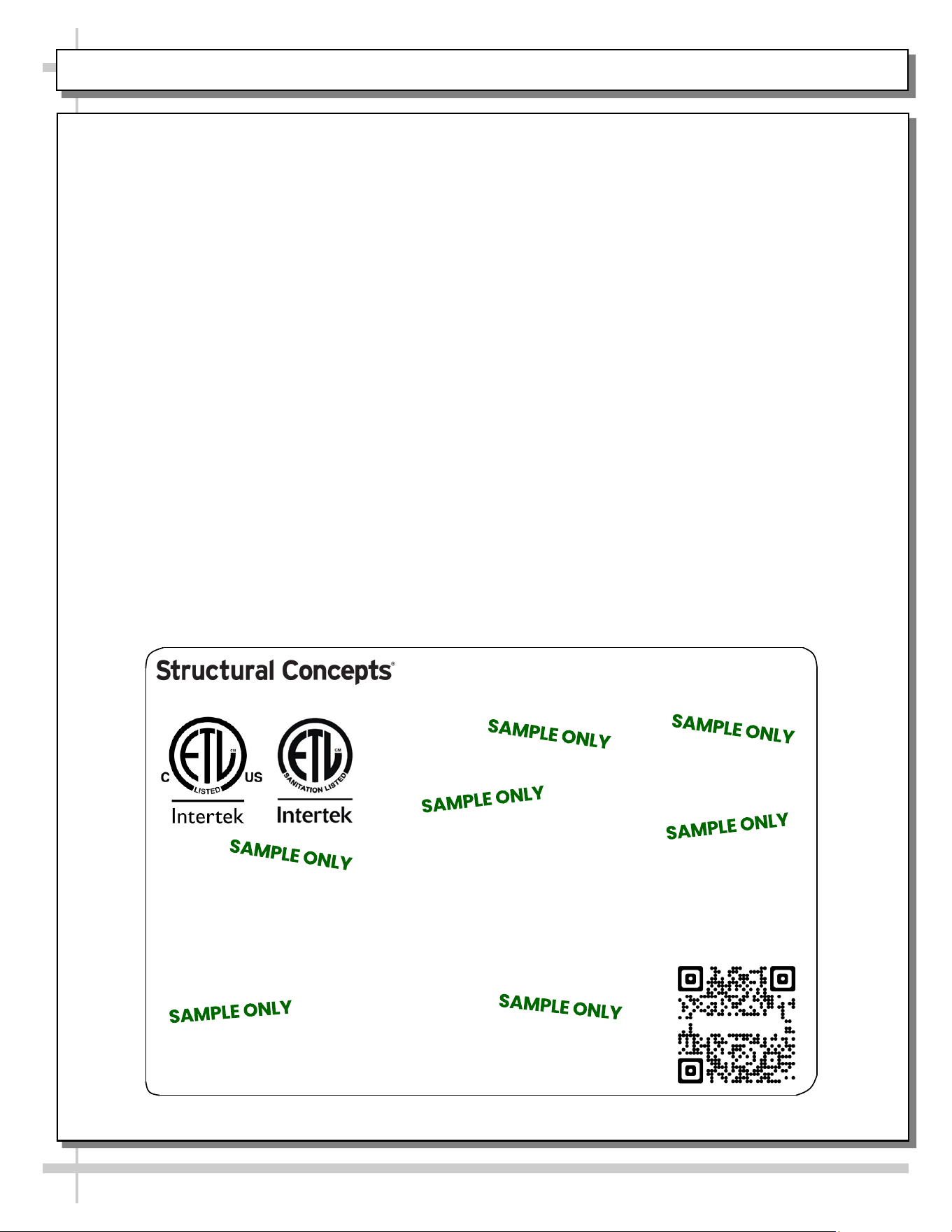
SERIAL LABEL LOCATION & INFO LISTED / TECH INFO & SERVICE / REFRIGERATED CASES ONLY
--- Sample Serial Label For Refrigerated Cases ---
MODEL NRS3648RXV-SAMPLE
SERIAL NO. 12345X30DZ098765
TYPE II DISPLAY REFRIGERATOR: THIS EQUIPMENT IS INTENDED FOR USE IN AN AREA
WHERE THE ENVIRONMENTAL CONDITIONS ARE CONTROLLED AND MAINTAINED SUCH
THAT THE AMBIENT TEMPERATURE DOES NOT EXCEED 80 °F (27 °C).
888 E. Porter Rd - Muskegon, MI 49441
3048256
Conforms to UL Std. 471
Conforms to NSF/ANSI Stds. 2 & 7
CERTIFIED TO CAN/CSA
STD C22.2 NO 120
ELECTRICAL RATING
REFRIGERANT
DESIGN PRESSURE
MINIMUM CIRCUIT AMPACITY
MAXIMUM OVERCURRENT
120/1/60 16 A
R513A AMOUNT 50 OZ
HIGH 186 LOW 88
20A
20A
Super Heat Temp 6-8 °F FOR PARTS AND SERVICE
Defrost 6 defrosts per day, 45 °F CALL 1-800-433-9490
Serial Label Location & Information Listed /
Technical Information & Service
• Serial labels are affixed at a wide range of places
(on the header, near thermostat, at case rear,
behind panels/toe-kicks, on electrical boxes, etc.).
• Serial labels contain electrical, temperature and
refrigeration information, as well as regulatory
standards to which the case conforms.
• Sample serial label shown below.
• For additional technical information and service, see
the TECHNICAL SERVICE page in this manual for
instructions on contacting Structural Concepts’
Technical Service Department.
Grocerant
Sample QR Code
SCAN FOR PRODUCT LITERATURE
STRUCTURAL CONCEPTS TECHNICAL SERVICE CONTACT INFORMATION & LIMITED WARRANTY
27
TECH SERVICE/WARRANTY CONTACT INFO:
1 (800) 433-9490 / EXTENSION 1
DAYS/HOURS AVAILABLE:
MONDAY - FRIDAY (CLOSED HOLIDAYS)
8:00 a.m. TO 5:00 p.m. EST
YOU MUST HAVE THE FOLLOWING INFO AVAILABLE
BEFORE CONTACTING STRUCTURAL CONCEPTS:
SERIAL NO. / MODEL NO. / STORE NO. / STORE
ADDRESS / DETAILS (PHOTOS, LEAK LOCATIONS,
DAMAGE, STORE’S AMBIENT CONDITIONS, ETC.)
To Access The Limited Warranty To Your
Case, Follow These Instructions:
> If Viewing This Document on Smart Phone,
Tablet or Computer, Select/Click On The QR
Code at Right.
> If Viewing This Document In Print (Hard
Copy), Scan The QR Code at Right With Your
Smart Phone or Tablet.