
User Manual
VT07-B22L/ VT07-B23L/ VT10-B21L
Version: 1.0
Due to the regular upgrades of systems and products, ZKTeco could not guarantee exact
consistency between the actual product and the written information in this manual.
Remark
Please follow the user manual for correct installation and testing. If
there is any doubt please call our tech-supporting and customer center.
Our company applies ourselves to reformation and innovation of our
products. No extra notice for any change. The illustration shown here is
only for reference. If there is any difference, please take the actual
product as the standard.
The product and batteries must be handled separately from household
waste. When the product reaches the end of service life and needs to be
discarded, please contact the local administrative department and put it in
the designated collection points in order to avoid the damage to the
environment and human health caused by any disposal. We encourage
recycling and reusing the material resources.

CATALOG
Product Features ............................................................ 1
Technical Parameters ...................................................... 1
Pictures ........................................................................... 2
Operations ...................................................................... 4
1. Dial .............................................................................. 5
2. Panel ........................................................................... 6
3. Message ...................................................................... 7
4. Security ....................................................................... 8
5. Concierge ................................................................. 12
6. Monitor ..................................................................... 13
7. Setup ........................................................................ 13
Web Settings ................................................................ 20
System Configuration .................................................. 24
System Diagram ........................................................... 25
Installation .................................................................... 27
Troubleshooting ........................................................... 29
Safety Instructions ....................................................... 30

1
Product Features
1.
Building intercom application:
Talkback: Support video call, monitoring, unlocking, and checking the call records.
Security: Support 8 alarm zones with 3 states, zone and scene setup.
Smart: Support smart home extension by RS485 communication (Optional).
2.
Operating system: Linux
Technical Parameters
Voltage: DC 12V
POE (VT07-B22L/VT07-B23L/VT10-B21L)
Rated power: 9W
12W (VT7-B22L, Switch (with Dual RJ45 Ports) )
Standby power consumption: 1.5W
3.0W (VT7-B22L, Switch (with Dual RJ45 Ports) )
Display screen: 7''/10.1''
Touch screen: Capacitive / Resistive touch screen
Resolution: 7'': 800x480
10.1'': 1024x600
Operating temperature: -10℃~+55℃
Storage temperature: -10℃~+60℃
Storage Relative humidity: 20%~85%
IP grade: IP30
2
Pictures
Model: VT10-B21L
Speaker
10.1'' capacitive
touch screen
Microphone
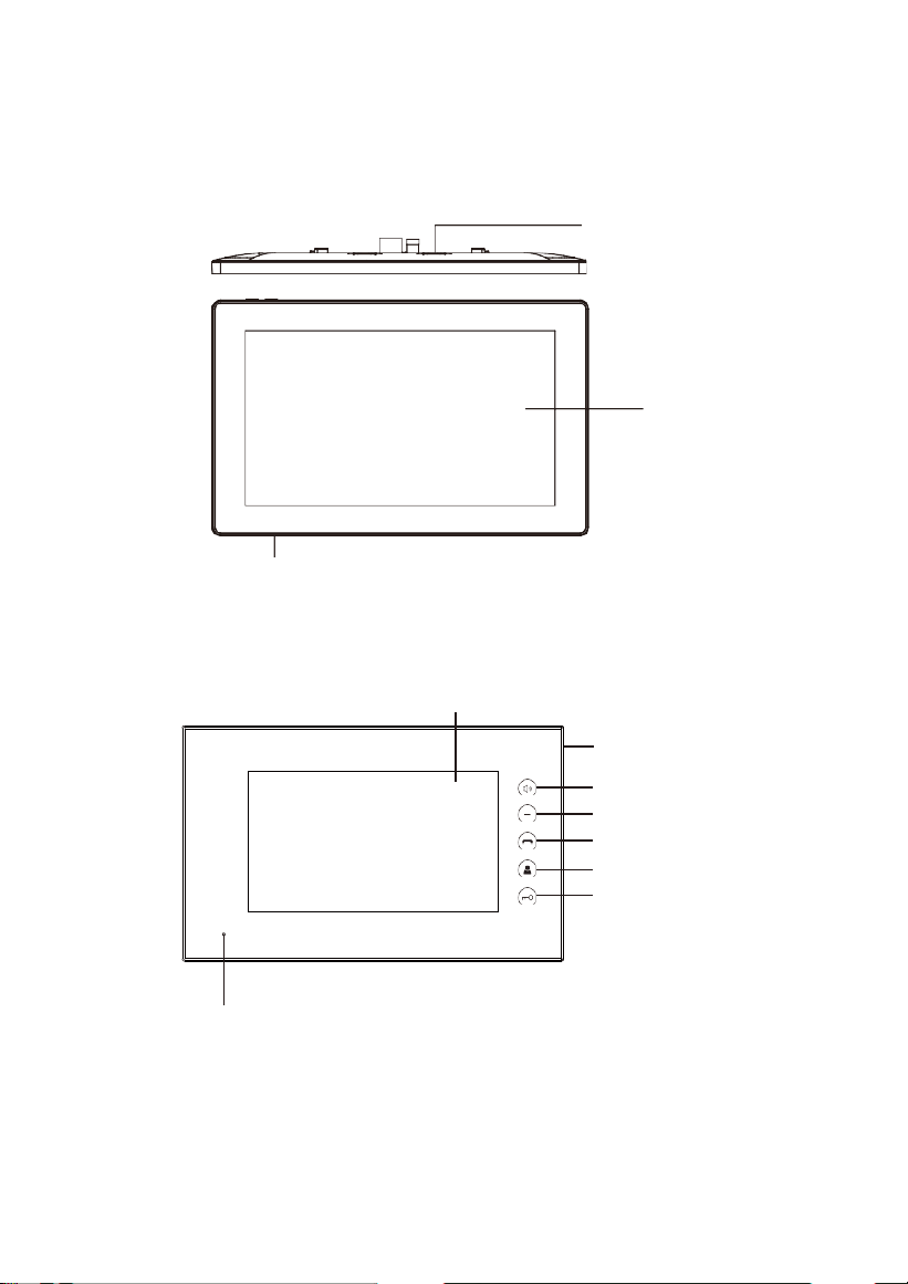
Model: VT07-C23L
7'' capacitive
touch screen
Speaker
Handsfree
Reserved
Calling management
center
Monitoring
Unlocking
Microphone
3
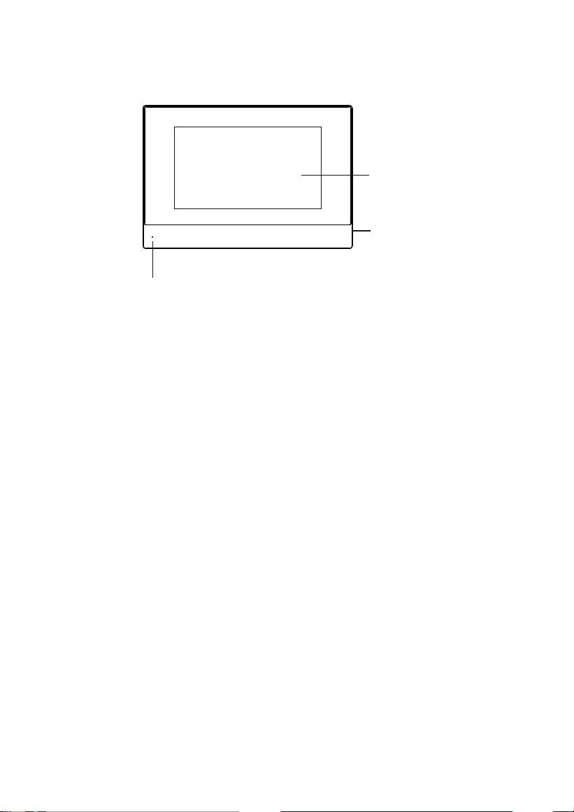
Model: VT07-C22L
7'' capacitive
touch screen
Speaker
Microphone
Indoor monitor doesn’t support the connection with external camera, audio
extension, Wi-FiI, Bluetooth, external USB and TF storage card.
Standard indoor monitor doesn’t include RS485 communication function.
Please contact the supplier if you have such requirement.
4
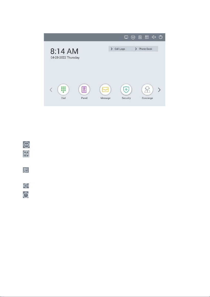
Operations
Main menu: Dial, Panel, Message, Security, Concierge, Monitor, Setup.
Instructions of status bar and shortcut key:
1.
Call logs: Click to
check call logs.
2.
Phone Book: Click to check and call contacts.
3.
SOS: Click to make a direct emergency call to Master Station.
4.
Lift control: Click to summon the elevator to go up or down. Click
Permit inside of it to release the floor button in the elevator.
5.
QR code: Click to scan QR code with Smart Life app to add this Indoor
Monitor to your phone.
6.
Mute: Click to mute.
7.
Turn off: Click to turn off the screen.
5
1.
Dial
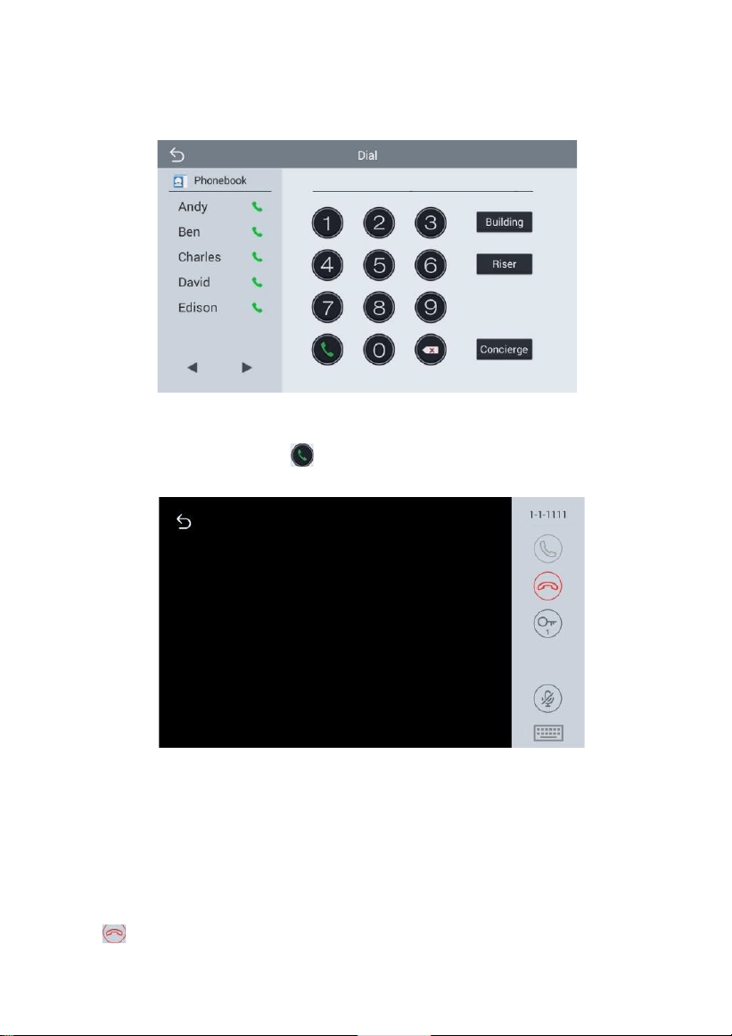
Click “Dial” icon, the system will enter the following interface:
1.1
Call Resident
Input 1-3 digits building No. +“Building”+ 2-digit Unit No. + “Riser”
+4-digit room No., then click
icon to call.
The system will enter into the following interface:
When the call is answered, the system will enter into call state:
1.
If there is a camera, the caller’s image will be displayed on the screen;
2.
When the call is answered, the video will be uploaded into the
indoor monitor.
When calling, the indoor monitor will ring; if there is no answer within 25
seconds, the call will be ended.
Click
icon to end the call.
6
1.2
Call Master Station
Click “ ” icon to call master station, the system will call master station No.1-
No.5 successively. If the master station cannot be searched or call failed, the
system will automatically call next master station. When the master station
answers, it will ring and stop calling next one.
Click
icon to end the communication.
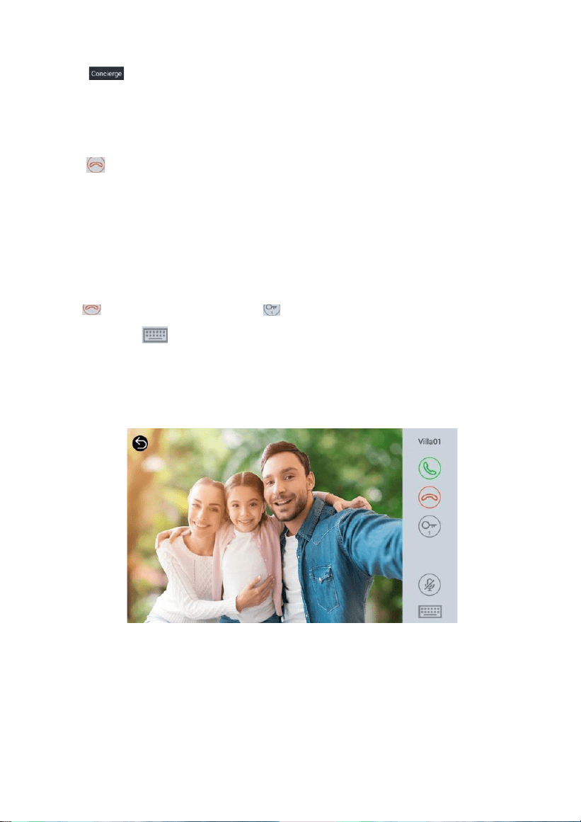
1.3
Receive Call from Door Station
When the door station, wall door station or secondary door station calls, the
indoor monitor will ring; when door station calls indoor monitor, the image
from door station will be displayed on the indoor monitor; if there is no
answer within 25 seconds, the call will be ended.
Click icon to end the call; click
icon to unlock the door.
Remark: Click icon to switch between answering interface and
monitoring interface of IP camera. After numeric keypad shows, press
number key "2" to "9" to select the IP camera and press "1" to return to
previous page.
2.
Panel
Click “Panel” icon on the main interface, the system will enter the
following
interface:
7
The door station can be monitored here. To switch the type of door station, please
follow the operations as below:
1.
Click icon to select the type of door station Click icon Click
“ ” to
start monitoring;
2.
Click icon Click “ ” icon to select the type of door station Click
“ ”
to start monitoring.
During monitoring, click “ ” icon to unlock the door.
Remark: The system’s default monitoring time is 25s.
3.
Message
Click “Message” icon on the main interface, the system will enter the
following interface:
8
Note: Indoor monitor can only receive the message sent by the
management software installed on the computer which is usually located at
guard center.
Up to 64 records can be received in SMS.
4.
Security
Click “Security” icon on the main interface, the system will enter the
following
interface:
4.1 ON/OFF
Click “ON/OFF” icon, the system will enter into the following interface:
9
4.1.1 ON
Click “Out”, “Home”, or “Sleep” icon to activate the alarm sensors, the
icon on the main interface will light up with a beep and stay lit.
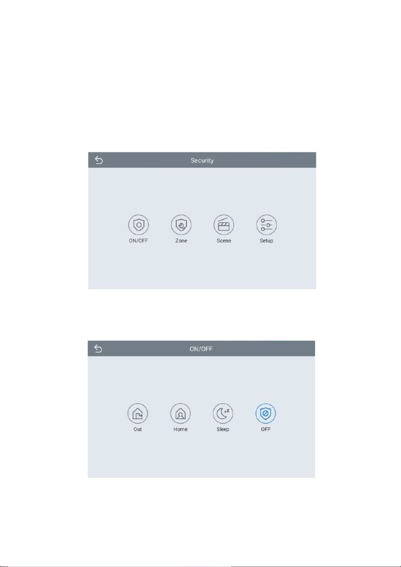
4.1.2 OFF
(1)
During delay time of the alarm, click “OFF” icon, the system will beep
to disable the alarm.
(2)
Input user password (the default password is 1234) to disable the
alarm under alarm ON status.
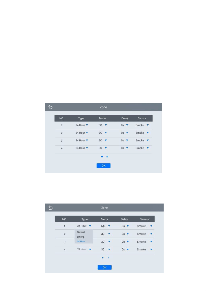
4.2 Zone
Remark: the settings should be made when alarm is OFF.
Click “Zone” icon and input 1-16 digits password (the default password is
1234), the system will enter into the following interface:
4.2.1 Alarm Type
Click Type, it will show as the following. In this interface, you can set
alarm
Type as: Normal, Emerg. or 24 Hour. 24 Hour and Emergency types
are always
active.
10
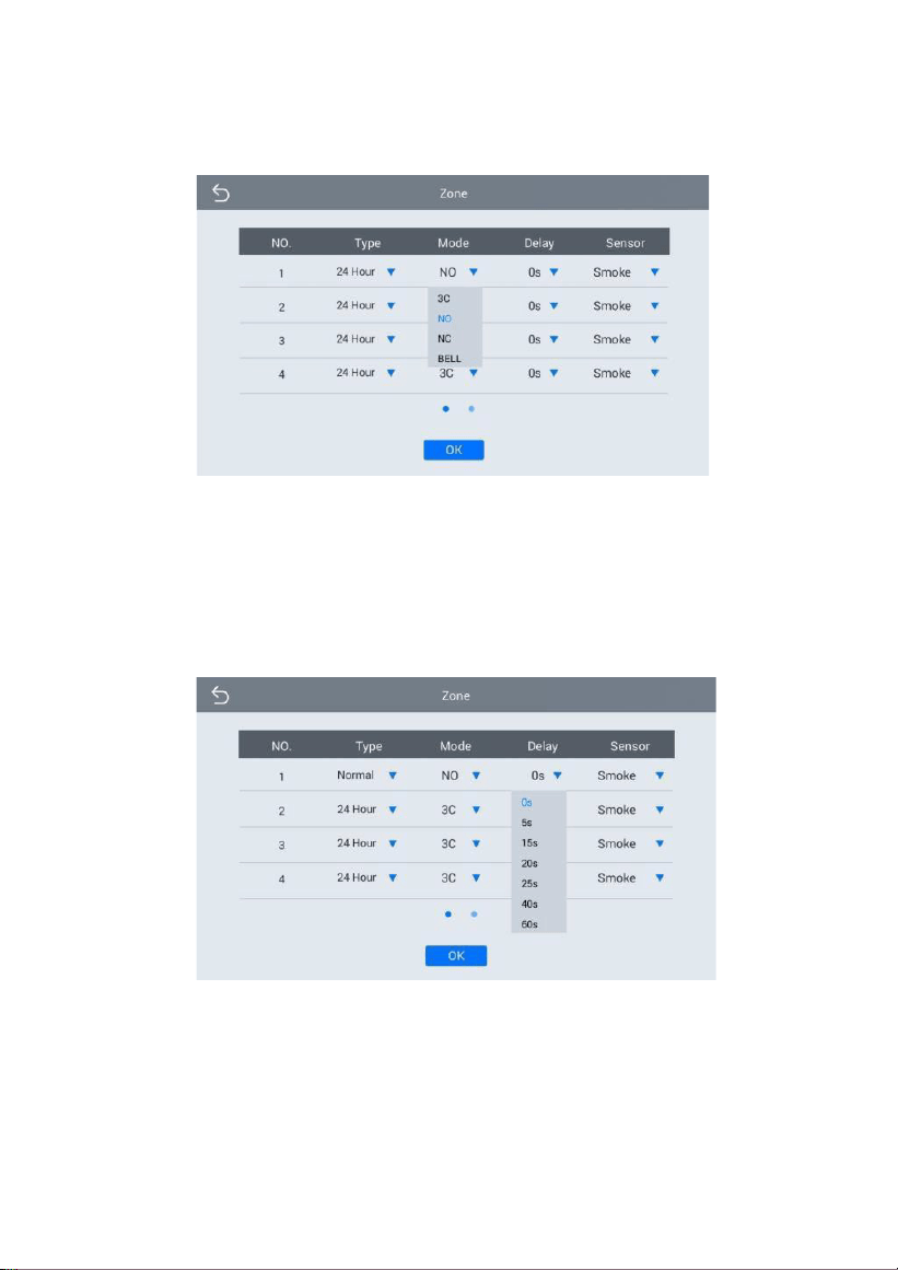
4.2.2 Mode
Click Mode, it will show the following interface. In this interface, you can set
mode as: 3C, NO, NC or BELL.
4.2.3 Delay Time
It refers to the delay time of giving an alarm. Click Delay setting, it will
show the following interface with selections: 0s, 5s, 15s, 20s, 25s, 40s or 60s
as the desired delay time. For example, select the delay time: 5s. Once the
alarm sensor is triggered, the indoor monitor will issue the sirens after 5
seconds.
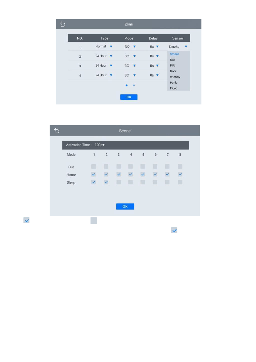
4.2.4 Sensor Type
Click sensor type, it will show the following interface. Each sensor type
can be set up as: Smoke, Gas, PIR, Door, Window, Panic, Flood.
11
4.3 Scene
Click “Scene” icon, the system will enter into the following interface:
refers to Alarm ON, refers to Alarm OFF. To set the sensor of alarm
stations, you can click the corresponding station with
icon. Click
"Activation Time" to select the corresponding time. The options of activation
time include NONE, 30s, 40s, 60s, 100s and 300s.
4.4 Setup
Click “Setup” icon, the system will enter into the following interface:
12
You can set the new system password with 1-16 digits (the default password
is 123456). System password is used for system settings.
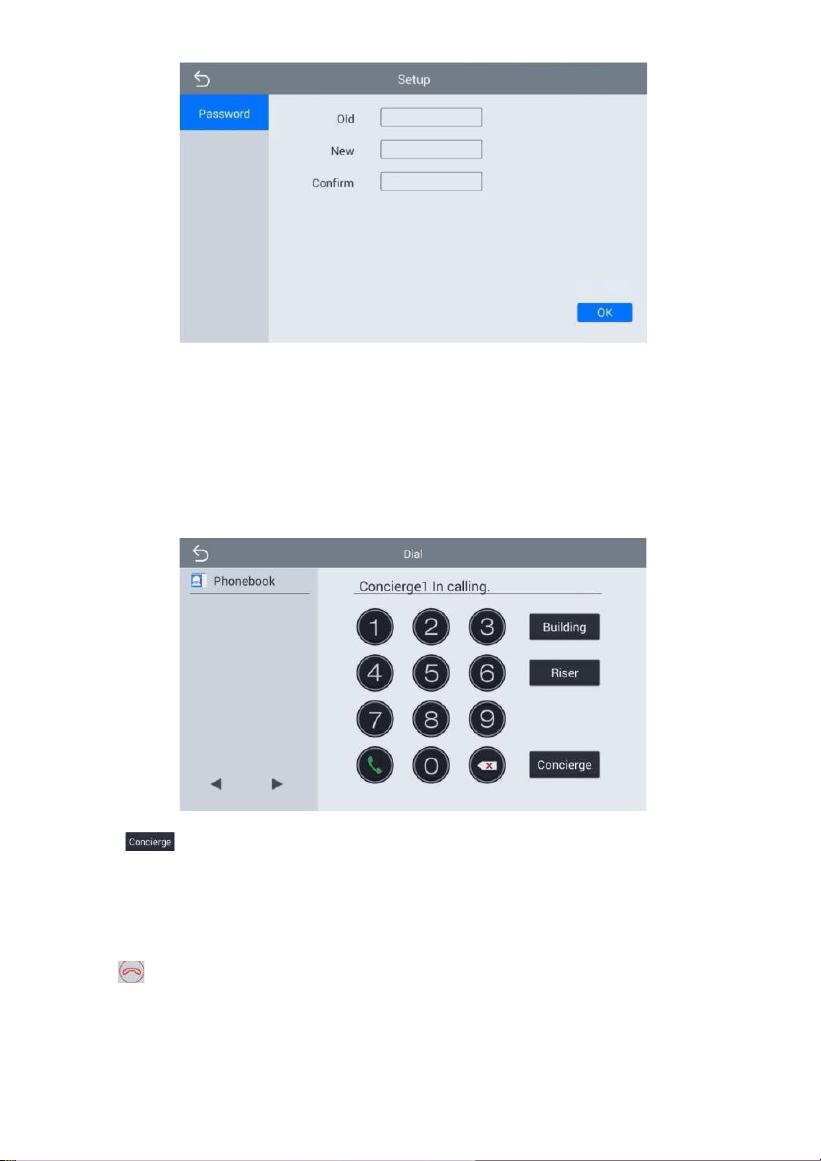
5.
Concierge
Click “Concierge” icon on the main interface, the system will enter
the following
interface:
Click “
” icon to call master station, the system will call master station
No.1-
No.5 successively. If the master station cannot be searched or call failed, the
system will automatically call next master station. When the master station
answers, it will ring and stop calling next one.
Click icon to end the communication.
13
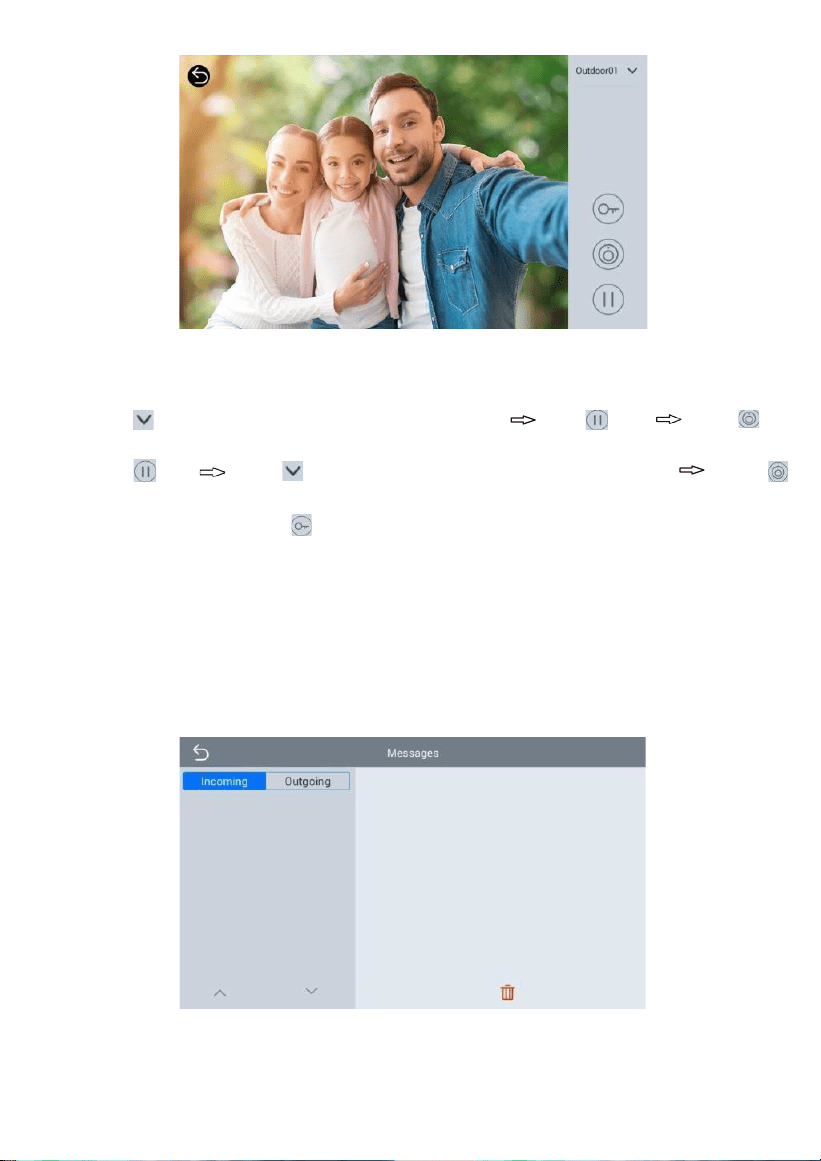
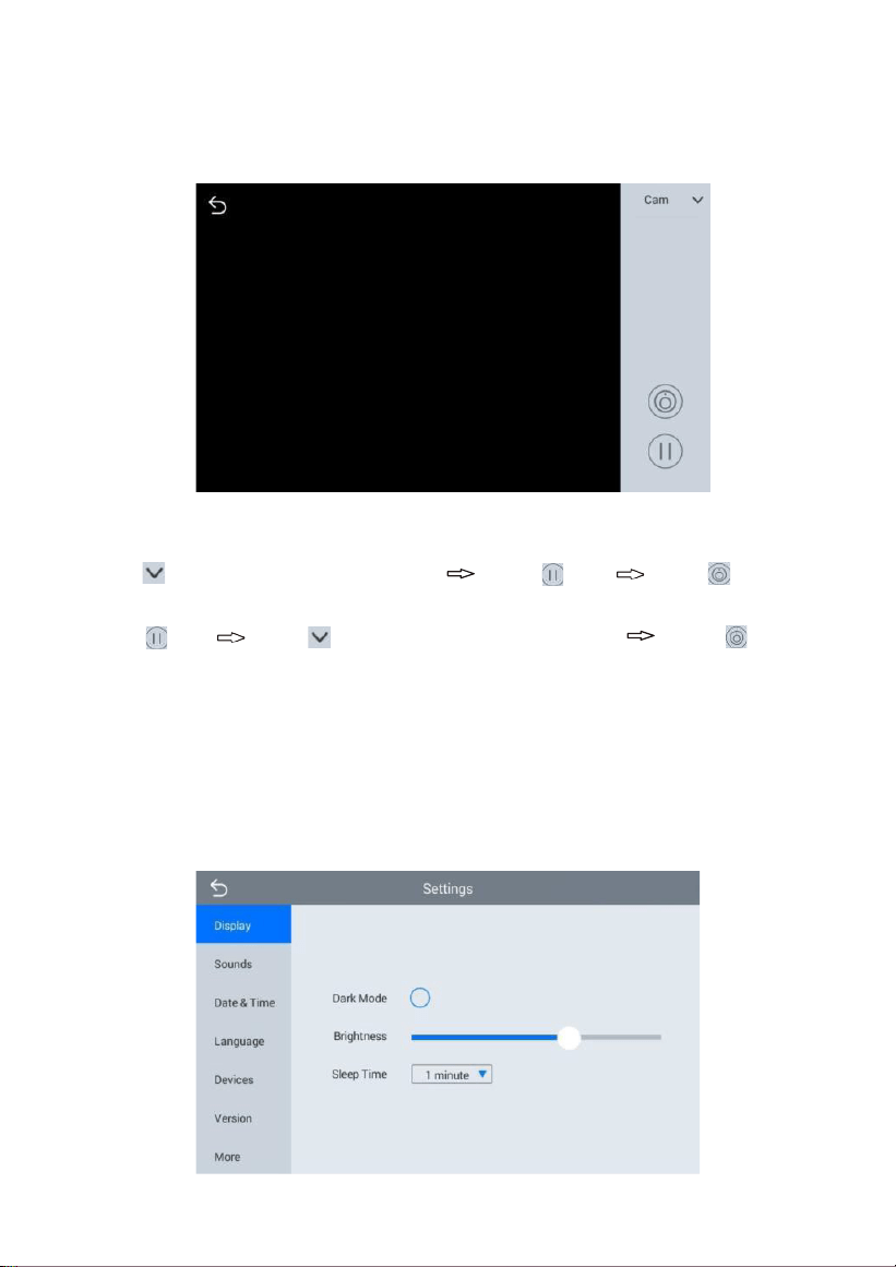
6.
Monitor
Click “Monitor” icon on the main interface, the system will enter the
following
interface:
The IP camera can be monitored here. To switch the type of IP camera,
please follow the operations as below:
1.
Click icon to select the camera Click icon
Click “ ” to
start monitoring;
2.
Click icon
Click “ ” icon to select the camera Click “ ”
to start
monitoring.
Remark: The system’s default monitoring time is 25s.
7.
Setup
Click “Setup” icon on the main interface to make the following settings.
7.1 Display
“Dark Mode”, “Brightness” and “Sleep Time” can be set
.
14
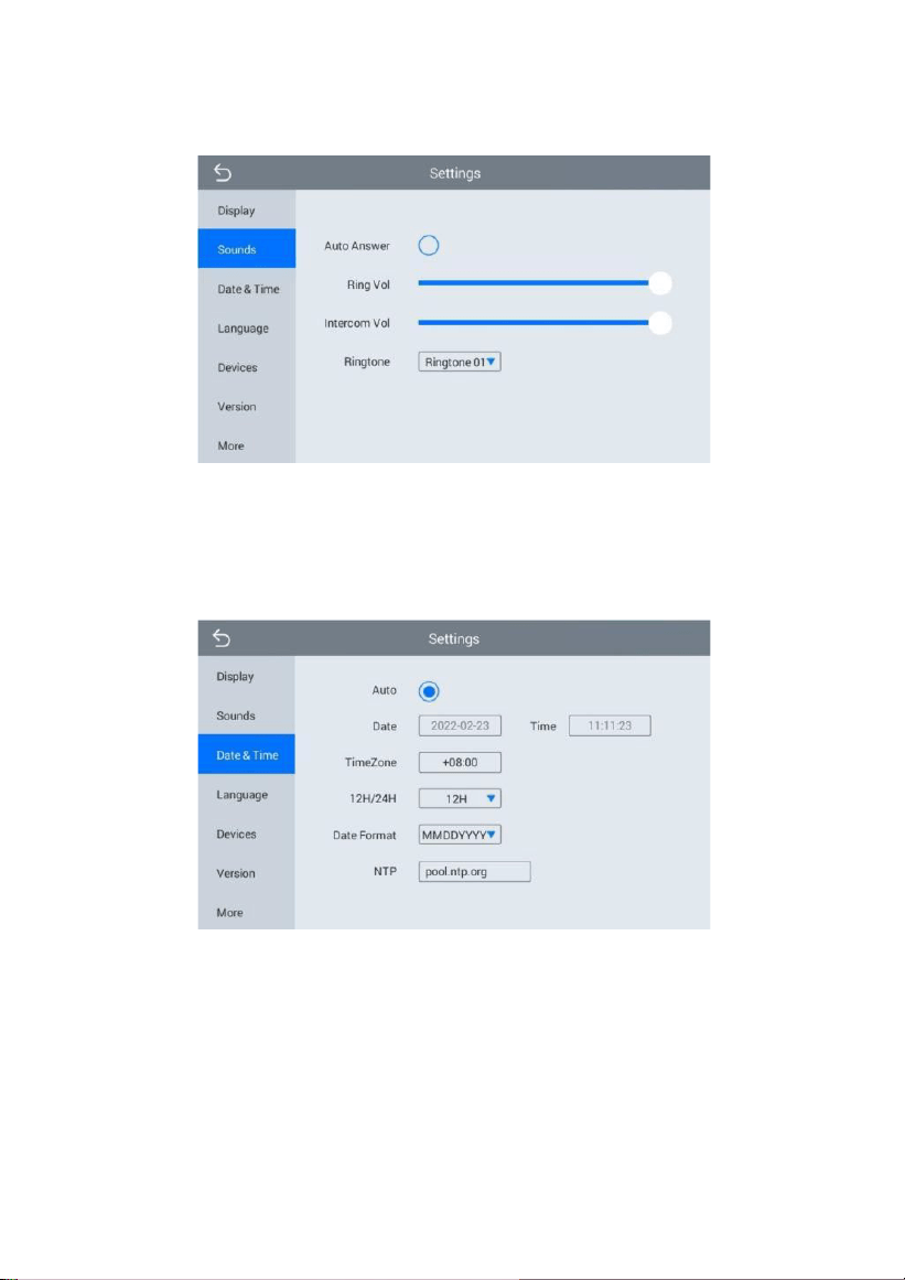
7.2 Sounds
Click “Sounds” icon, the system will enter into the following interface:
“Auto Answer”, “Ring Vol”, “Intercom Vol” and "Ringtone" can be set.
7.3 Date & Time
Click “Date & Time” icon, the system will enter into the following interface:
This interface can set “Auto”, “Date”, “Time Zone”, “12H/24H”, “Date Format”
and “NTP”.
7.4 Language
Click “Language” icon, the system will enter into the following interface:
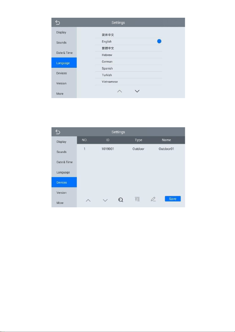
15
The system language can be switched.
7.5 Devices
Click “Devices” icon, the system will enter into the following interface:
The device information can be viewed.
7.6 Version
Click “Version” icon, the system will enter into the following interface:
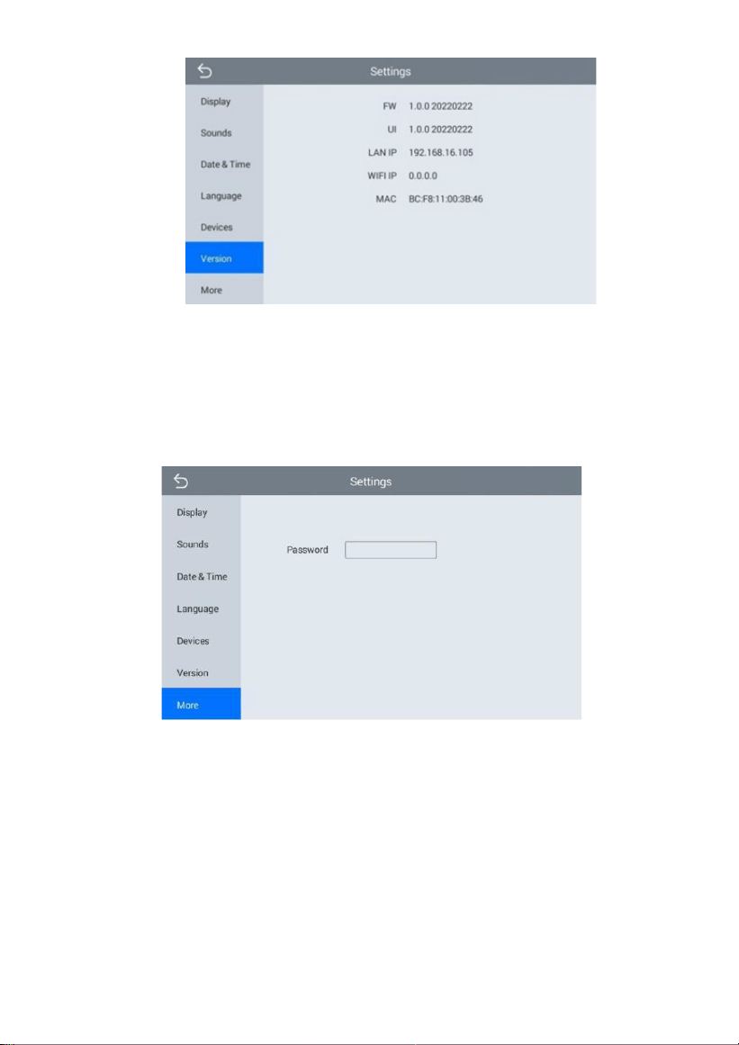
16
Version information includnig “FW”, “UI”, “LAN IP”, “WiFi IP” and “MAC”
can be
viewed.
7.7 More
Click “More” icon, then input 1-16 digits password (the default password is
123456) to make the following settings:
7.7.1 Network
Click “Network” icon, the system will enter into the following interface:
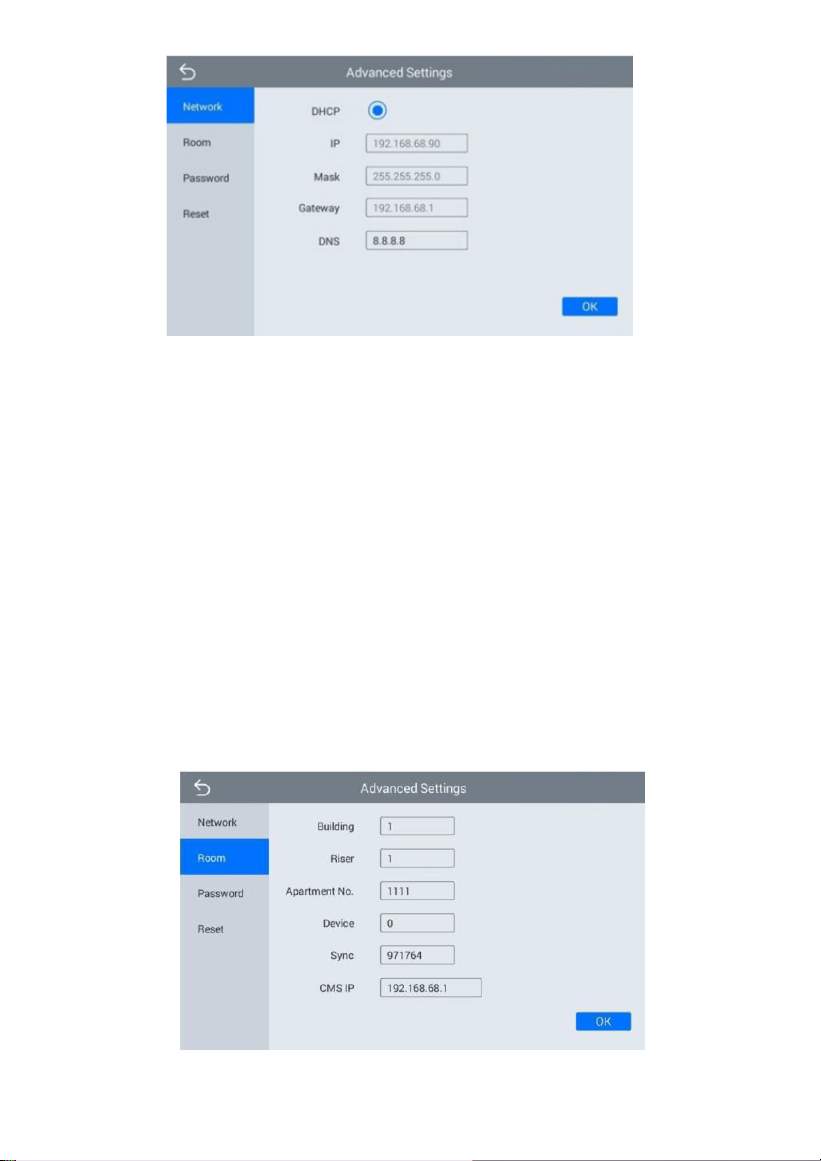
17
After using the DHCP, the router will automatically distribute IP address.
Other settings are the same as the ones of Smart Life APP. IP: Static IP
address.
Mask: The default Mask address is 255.255.255.0. Normally, it can keep
unchanged. To modify it, click the setting box twice, a keypad will pop up
for entering new Mask address.
Gateway: The Gateway in one system must be in the same segment. DNS: It
refers to name resolution address (DNS of local operator). If the indoor
monitor is used in external network, the address must be completed
correctly; if it is used in internal network, the address can be ignored.
7.7.2 Room
Click “Room” icon, the system will enter into the following interface:
18
Warning: Please revise Sync No. (6 digits) as soon as possible after you read
the user manual. The Sync No. of all indoor monitors in one household must
be the same.
Input the 3-digit Building No. such as 001, and then click “OK” to
finish the
building No. setting.
The setting method of Riser No., Apartment No., Device No., CMS IP and Sync
No. is the same as the one of Building No.. When Device No. is set to be 0, the
indoor monitor is regarded as the main; when Device No. is set from 1 to 5,
the monitor is regarded as the sub1 to sub5.
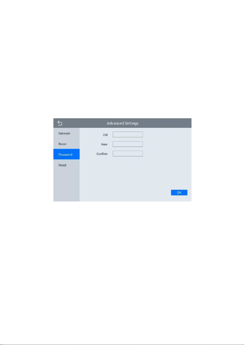
7.7.3 Password
Click “Password” icon, the system will enter into the following interface:
You can set the new system password with 1-16 digits (the default
password is 123456). System password is used for system settings.
7.7.4 Reset
Click “Reset” icon, the system will enter into the following interface:
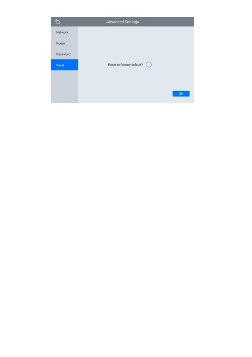
19
To confirm the operation, click OK.
20
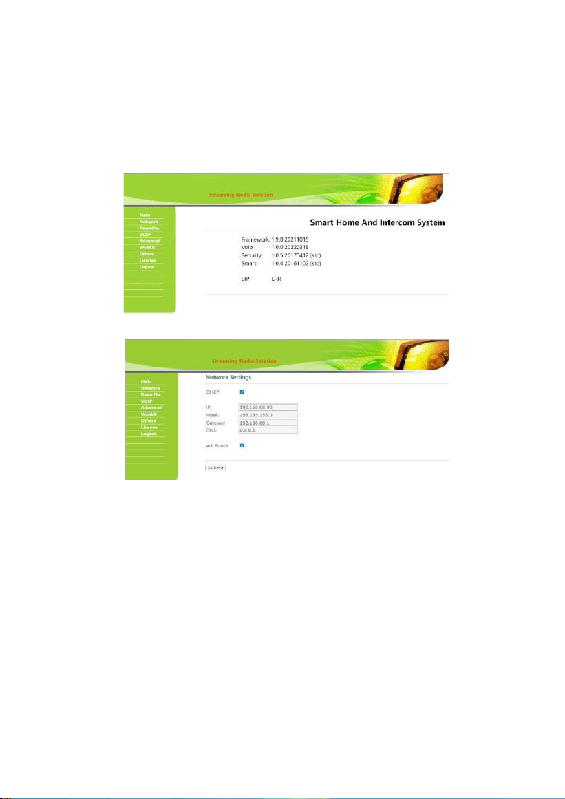
WEB SETTING
Connect the indoor monitor and computer by network switch. Input the
indoor monitor’s IP address in the browser, then input user name and
password (the default user name is “admin”, the password is “123456") to
enter into the web setting interface.
Main page is used for showing firmware version and the status of SIP registration.
1.
Network
Network page is used for setting up network of device here.
DHCP: obtain IP address via DHCP;
IP: static IP address;
Mask: subnet mask;
Gateway: gateway;
DNS: Domain Name Server;
Eth & Wi-Fi: switch to activate network port and Wi-Fi of the device to work
simultaneously.
21
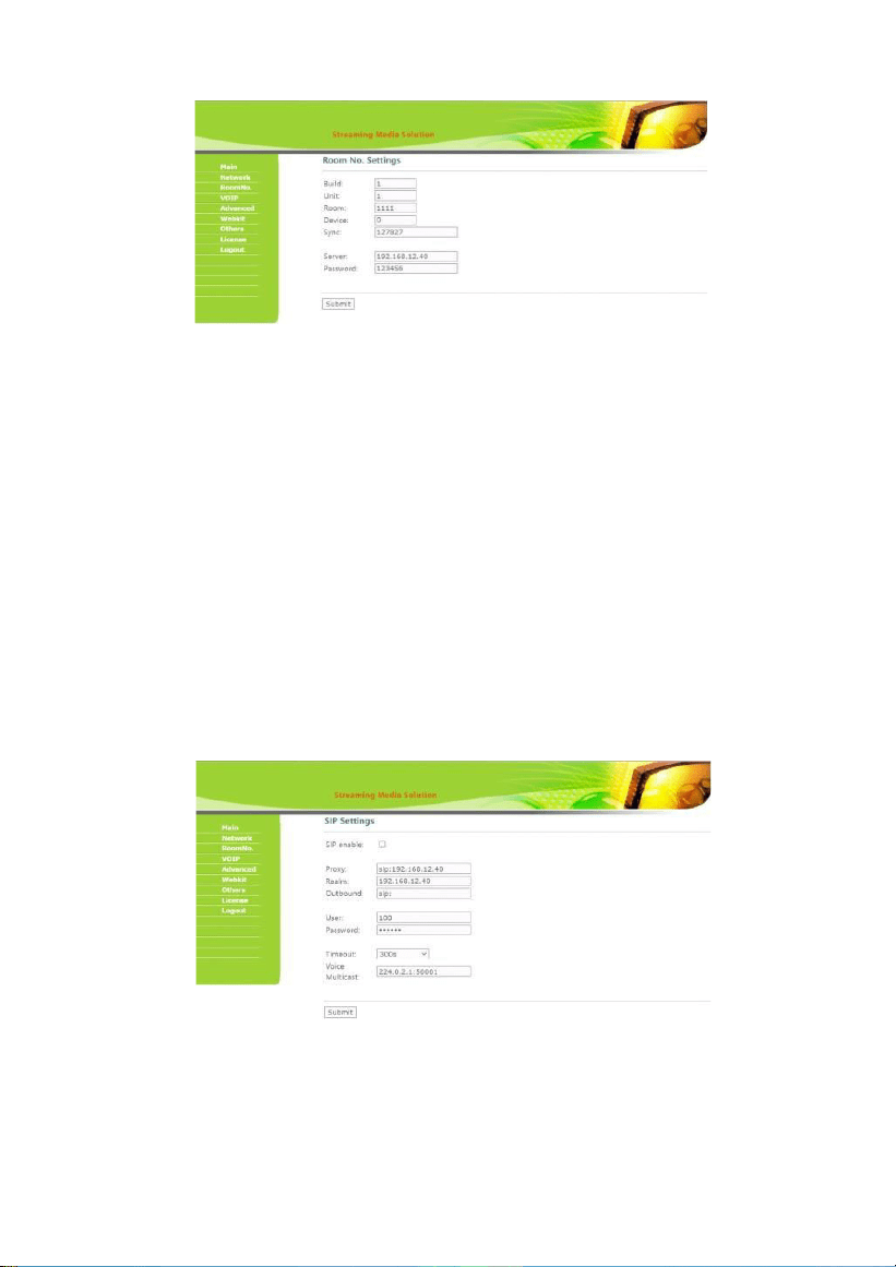
2.
RoomNo
RoomNo page is used for setting up connection with other
devices.
Build: number of the building;
Unit: number of the unit;
Room: number of the room;
Device: the numbering system for same-room number devices (Indoor
Monitor 0-9; Outdoor Station 1-9);
Sync: type in same numbers to make same-room number Indoor Monitors ring
together;
Server & Password: server is the IP of CMS and password is the
admin’s password
of device.
3.
VOIP
VOIP page is used for setting up SIP.
SIP enable: switch to enable or disable SIP;
Proxy: fill server address and port, the format: sip:server@IPaddress:port;
22
Realm: fill server address and port, the format: server@IPaddress:port;
Outbound: if you don't have outbound server, leave it blank;
User & Password: account and password of SIP;
Timeout: maximum call duration;
Voice Multicast: fill voice gateway to receive voice broadcast.
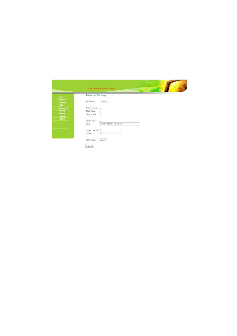
4.
Advanced
Advanced page is used for setting up accessibility features.
Ex Phone: add other brand's IP Phone as SIP extension (4 devices
supported);
Auto Pickup: pick up automatically when receiving a call;
ONU Pass: if using optical cable but not network cable in the building, it
should be enabled;
Deaf Mode: enable this when Indoor Monitor connecting a lamp for
ringing;
Quick Call & URL: call the corresponding URL by management-center
button or icon;
DTMF Unlock & DTMF: enable sending DTMF command;
RTSP Feed: the video source of the Indoor Monitor when call another
Indoor Monitors.
23
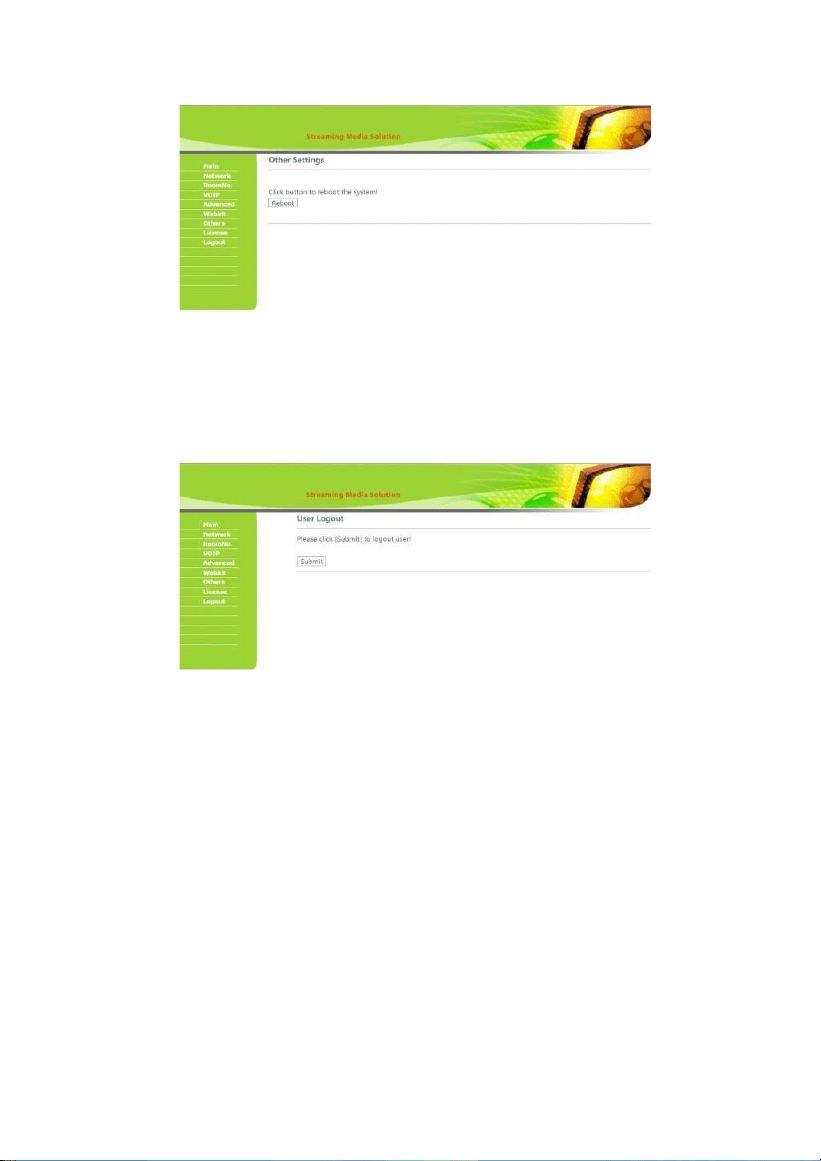
5.
Others
Others page is used for reboot.
Reboot: click to reboot the device.
6.
Logout
Logout page is used for signing off.
User Logout: click to logout the webpage. After that, you can use other
accounts to login.
24
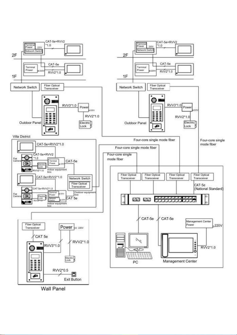
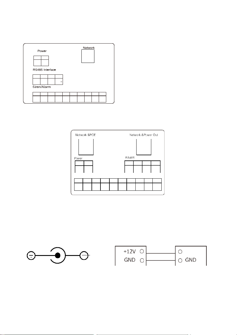
System Configuration
25
Siren/Alarm
1 2
+12V GND
1 2 3 4
+12V
GND 485+ 485-
+12V
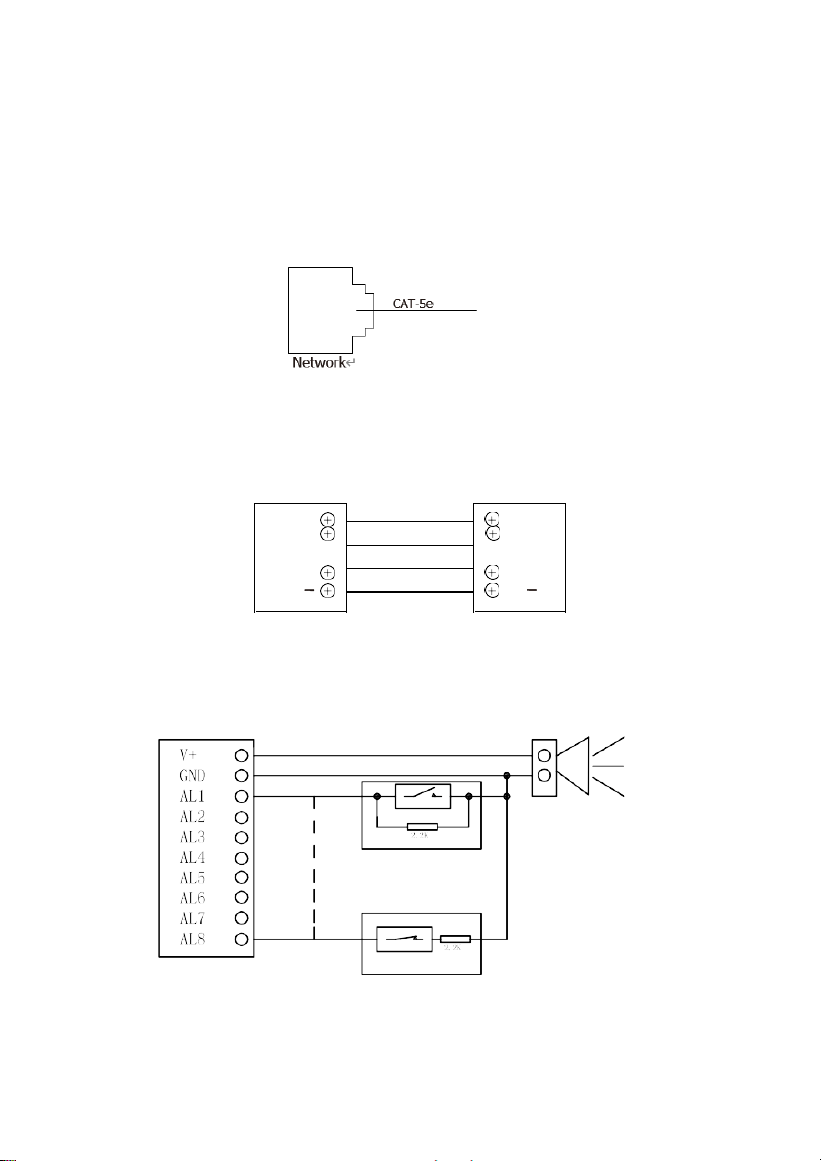
System Diagram
1
2
+12V
GND
1
2
3
4
+12V
GND
485+
485
1
2
3
4
5
6
7
8
9
10
V+ GND AL1 AL2 AL3 AL4
AL5
AL6
AL7
AL8
(Standard)
1
2
3
4
5
6
7
8
9
10
V+
GND
AL1
AL2 AL3 AL4
AL5
AL6
AL7
AL8
(VT07-B22L, Switch (with Dual RJ45 Ports) )
1.
Power
Power input interface connects with 12V power adapter.
DC 12V
Power
12V Power
26
Network
2.
Network
Connect with outdoor panel, indoor monitor or other network equipment by
network switch.
When indoor monitor has POE function, the interface can supply power by connecting with
POE network switch. If network interface has 12V power supply, pin No. 4 and 5 of RJ45
interface should connect with +12 of power interface, and pin No. 7 and 8 should connect
with GND of power interface.
3. RS485
Connect with RS485 interface device;
RS485 interface can output 12V/100mA power supply. If RS485 equipment to be
connected doesn’t require the power supply, no need to connect +12V.
+12V
+12V
GND
GND
485
+
485
+
485
485
RS485 Interface RS485 Equipment
4. Siren/Alarm
When alarm sensor is triggered, the output power is 12V/100mA.
Each interface of alarm zone can be connected with normally-open or normally
-closed switch.
Alarm facility
Normally-open sensor
Alarm
Normally-closed sensor
27
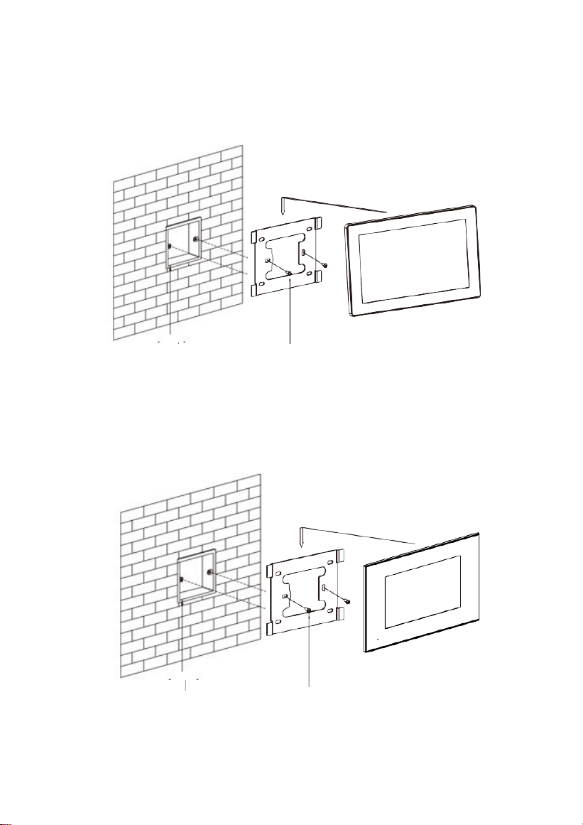
Installation
Model: VT10-B21L
Built-in box Screws
Size: 270*168*15mm
Model: VT07-C23L
Built-in box Screws
Size: 235*145*19.5mm
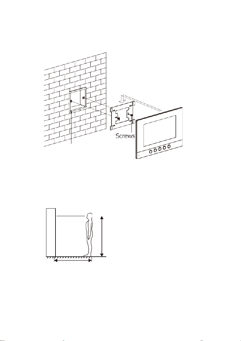
28
Built-in box
Model: VT07-C22L
Size: 221.4*151.4*16.5mm
Installation Instructions:
400~500mm
[Suggestion]: During the
installation, the camera should be
1450 〜 1550mm above the
ground. The camera tether for
photographing human face
should be the top priority.
Wall
1450~1550mm

29
Troubleshooting
The indoor monitor cannot start up or power off automatically.
Check whether it has power-failure, and power it on again.
The indoor monitor display screen is too dim.
Check whether the brightness and contrast settings of screen are correct.
No sound during the communication.
Check whether the indoor monitor is set as mute mode, or the volume is
set to the lowest.
The indoor monitor cannot monitor the outdoor panel.
Other user is using the system, so you can use it once he/she
finished the operation.
Multimedia files cannot be played normally.
Check whether the system supports the file format. Please refer to multimedia
setting for details.
No response when clicking indoor monitor display screen.
Press “Unlock” button for 5s, or slowly slide horizontally or vertically on the LCD
to make touchscreen calibnation. It needs to be calibrated twice.
Touchscreen responses slowly or cannot make calibnation.
Take down any protective paster, since it may affect identification and
input for device;
Ensure the finger is dry and clean when clicking touchscreen;
Restart the device to clear any temporary software error.
The temperature of device is too high.
Long-term use leads to high temperature. It’s normal and will not affect
the device’s use life and performance.

30
Safety Instructions
In order to protect you and others from harm or your device from damage, please read the
following information before using the device.
Do not install the device in the following places:
Do not install the device in high-temperature and moist environment or the area close
to magnetic field, such as the electric generator, transformer or magnet.
Do not place the device near the heating products such as electric heater or the fluid
container.
Do not place the device in the sunshine or near the heat source. This might cause
discoloration or deformation of the device.
Do not install the device in an unstable position to avoid the property losses or
personal injury caused by the falling of device.
Guard against electric shock, fire and explosion
Do not use damaged power cord, plug or loose outlet.
Do not touch the power cord with wet hands or unplug the power cord by
pulling.
Do not bend or damage the power cord.
Do not touch the device with wet hands.
Do not make the power supply slip or cause the impact.
Do not use the power supply without the manufacturer's approval.
Do not have the liquids such as water go into the device.
Clean Device Surface
Clean the device surfaces with soft cloth dipped in some water, and then rub the
surface with dry cloth.
Other Tips
In order to prevent damage to the paint layer or the case, please do not expose the
device to chemical products, such as the diluent, gasoline, alcohol, insect-resist
agents, opacifying agent and insecticide.
Do not knock on the device with hard objects.
Do not press the screen surface. Overexertion might cause flopover or damage to
the device.
Please be careful when standing up from under the device.
Do not disassemble, repair or modify the device at your own discretion. The
arbitrary modification is not covered under warranty. When any repair required,
please contact the customer service center.
If there is abnormal sound, smell or fume in the device, please unplug the
power cord immediately and contact the customer service center.
When the device isn’t used for a long time, the adaptor and memory card can be
removed and placed in dry environment.
When moving, please hand over the manual to new tenant for proper usage of the
device.

31
ZKTeco Industrial Park, No. 32, Industrial Road,
Tangxia Town, Dongguan, China.
Phone : +86 769 - 82109991
Fax : +86 755 - 89602394
www.zkteco.com
Copyright © 2024 ZKTECO CO., LTD. All Rights Reserved.


