OWNER’S MANUAL AND SAFETY INSTRUCTIONS
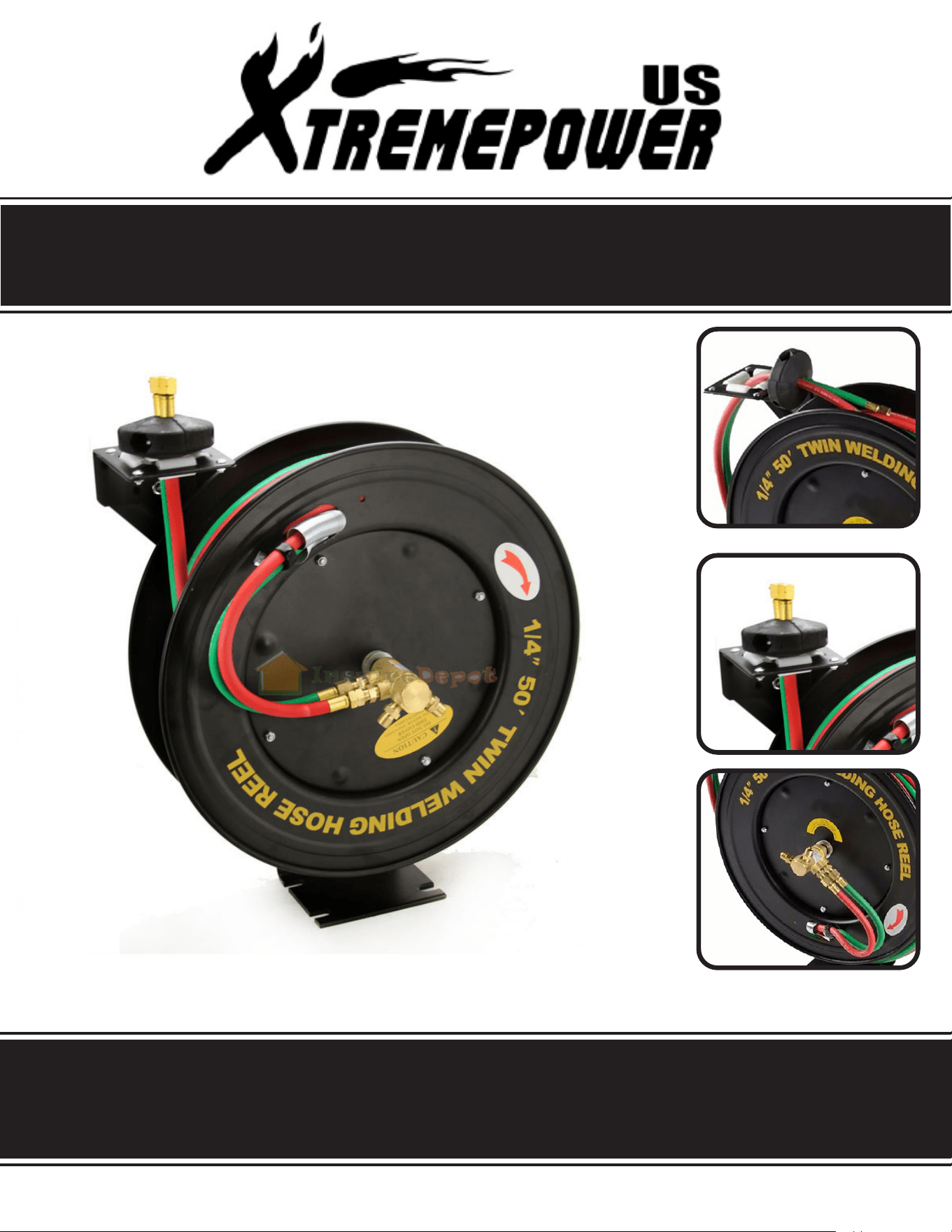
50’ X 1/4” WELDING HOSE REEL
ITEM # 43552
SAVE THIS MANUAL. KEEP THIS MANUAL FOR SAFETY WARNINGS, PRECAUTIONS, ASSEMBLY,
OPERATION, INSPECTION, MAINTENANCE AND CLEANING PROCEDURES. WRITE THE PRODUCT’S
SERIAL NUMBER ON THE BACK OF THE MANUAL, OR THE MONTH AND YEAR OF PURCHASE IF
PRODUCT HAS NO SERIAL NUMBER
FOR QUESTIONS, PLEASE CALL CUSTOMER SERVICE: 909.628.0880
SAFETY WARNINGS
Read all safety warnings and instructions. Failure to follow the warnings and instructions may result in
injury and/or property damage. Save all warnings and instructions for future reference.
The warning and safety instructions in this manual are not meant to cover all possible conditions and
situations that may occur. Common sense, caution and care must be exercised when operating or
cleaning tools and equipment. Always contact your dealer, distributor, service agent or manufacturer
about problems or conditions you do not understand before operating the product.
Keep the work area clean and well lit. A cluttered work area may cause accidents. Never allow children to
use this product. When operating this product, keep children and animals at a safe distance from the work
area.
When not in use, store product in a secure, dry and safe place. The storage area should be out of the reach
of children. Never use the hose for anything other than its intended purpose. Maintain this product with care.
DO NOT exceed maximum operating pressure of 300PSI for your model hose reel.
Use proper eye protection when assembling and using the hose reel.
Use soap and water when checking for leaks.
WARNING: Exposure of skin directly to pressurized air or uid could result in severe bodily injury.
Be aware of all power lines, electrical circuits, water pipes and other mechanical hazards in your work area,
particularly those hazards below the work surface hidden from the operator’s view that may be unintentionally
contacted and may cause personal harm or property damage.
Be alert of your surroundings. Using this hose reel in conned work areas may put you dangerously close to
cutting tools and rotating parts.
Do not modify this product in any way. Unauthorized modication may impair the function and/or safety and
could aect the life of the equipment. There are specic applications for which this product was designed.
Always check for damaged or worn out parts before using this hose reel. Broken parts will aect the operation.
Replace or repair damaged or worn parts immediately.
Mount the hose reel on a surface capable of supporting the hose reel and its maximum load.
SAVE THESE WARNINGS.
1

SAFETY WARNINGS SAFETY WARNINGS
SAVE THESE WARNINGS.
1 2
1. Read all of the instructions and safety warnings provided with your welding tanks, cutting torch, .and given
by the acetylene/oxygen distributor prior to operation. Also, read all of the instructions and safety precautions
as outlined in the manufacturers manual for the material you will weld or cut.
2. Risk of Fire and/or Explosion
Warning!! Leaking Acetylene and Oxygen are extremely hazardous and may result in explosion and re
resulting in SERIOUS INJURY and DEATH.
Turn o gas supply when not in use.
Working pressure on the acetylene regulator should NEVER be set above 15 PSI.
Always use reverse ow check valves on the torch and regulator. This greatly reduces the possibility of
mixing gases in the regulator or hose.
Don’t direct the gas ame near the Hose, HOSE Reel, or Tanks.
Use regulators for both oxygen and acetylene. Connect oxygen and acetylene intake hoses correctly,
following the manufacturer’s safety guidelines. Make sure the incoming pressure does not exceed the
maximum operating pressure of 200 PSI.
Locate the Hose Reel In a wall ventilated arts.
Check for leakage periodically. If any leakage is found, immediately shut down and purge the system. Have
the equipment repaired or replaced by an authorized service technician.
When Installing or replacing O-ring seals, only use silicon as a lubricant. Do not allow any grease or oil on
or in the connections or hoses. These materials ignite and easily burn in the presence of oxygen.
Secure cylinders to a car, wall, or post to prevent them from falling. All cylinders should be stored tn an
upright position. Never strike or drop a cylinder. Do not used dented cylinders. Cylinder caps should be used
when moving or storing a cylinder.
3. Avoid overexposure to fumes and gasses. Work in a well ventilated area and do not breathe fumes Use
mechanical ventilation systems to improve air quality Always use an approved respirator.
4. When working with cylinders, always “crack” the cylinder valves by standing to one side and quickly opening
and closing the valve, allowing gas to escape, clearing the valve of any foreign material. If oil or grease is
found, discontinue using the cylinder and immediately contact your supplier.
5. When attaching GREEN oxygen regulators (not included) to the oxygen cylinder, or RED acetylene
regulators (not included) to the acetylene cylinder, make sure they are tightened in the correct direction,
(normally, clockwise for oxygen and counts,clockwise for acetylene).
OPERATION
3
1. Before attaching the Base (1) to a wall or ceiling, make sure the mounting surface is capable of supporting
the weight of the Hose Reel and hose, and can withstand the stress of pulling and retracting the hose.
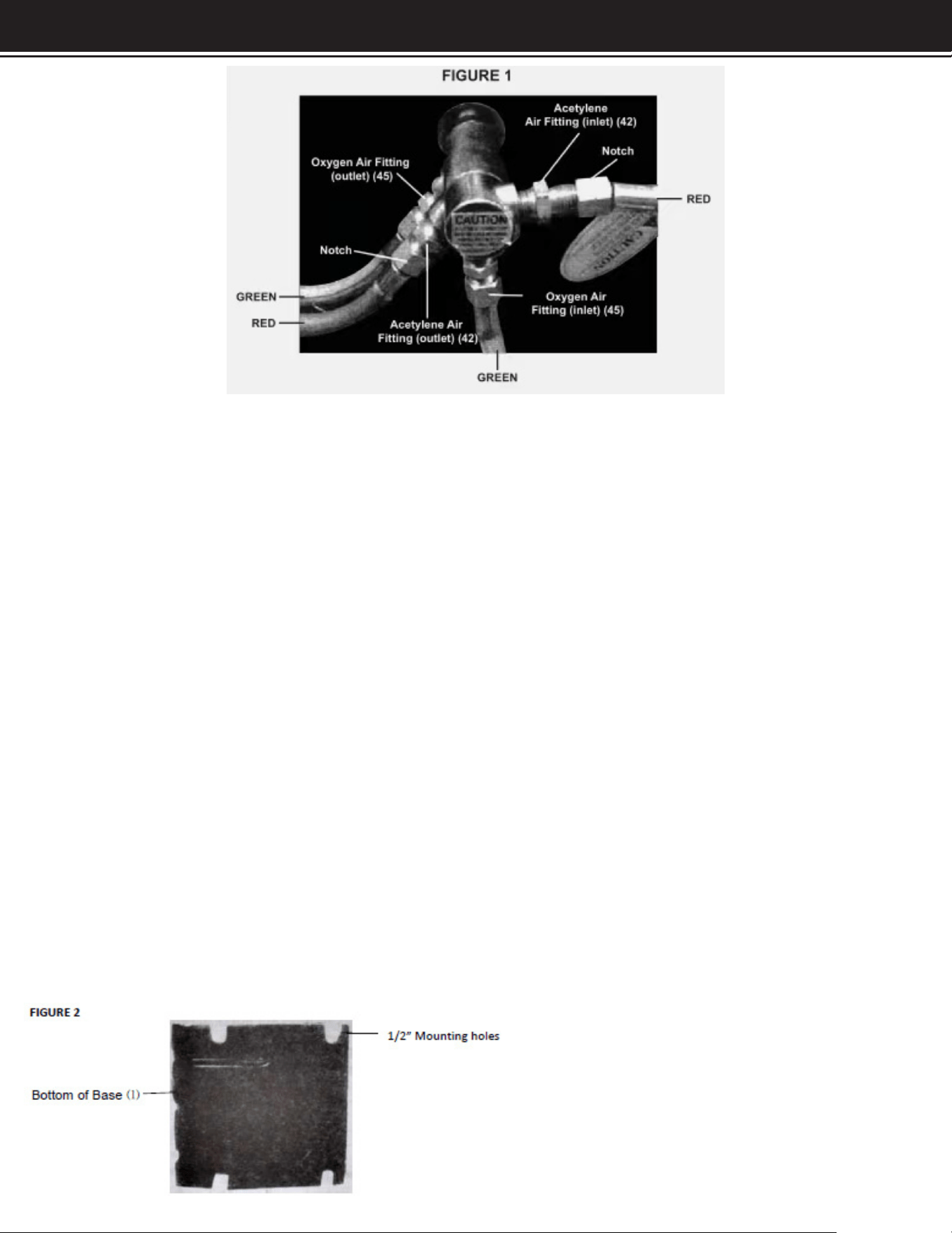
WARNING: When connecting, make sure you connect RED acetylene hoses with notches (left-handed
threads), to the connections with notches (left-handed threads). Connect the GREEN oxygen hoses without
notches to the connections without notches. See FIGURE 1, above.
INSTALLATION
Note: For ceiling mounting, mount the Hose Reel high enough above the oor to avoid contact with people and
equipment.
2. The Support Plate (2) may be adjusted so that the Hoses (47) leave the Reels on either side. 7b change its
position:
A. Pull out some hose and let the reel latch (click and stop).
B.
Remove the Bolts (12) that hold the Support Plate in place.
C. Rotate the Support Plate into the correct position. Replace the Bolts (12) and tighten.
WARNING: BEFORE ATTEMPTING ANY DRILLNG into walls or ceilings, make certain no electrical wires
are In the Way or behind the surface you are drilling into.
Make sure the mounting surface is solid. If going through sheet rock it must have studs for the bolts to penetrate.
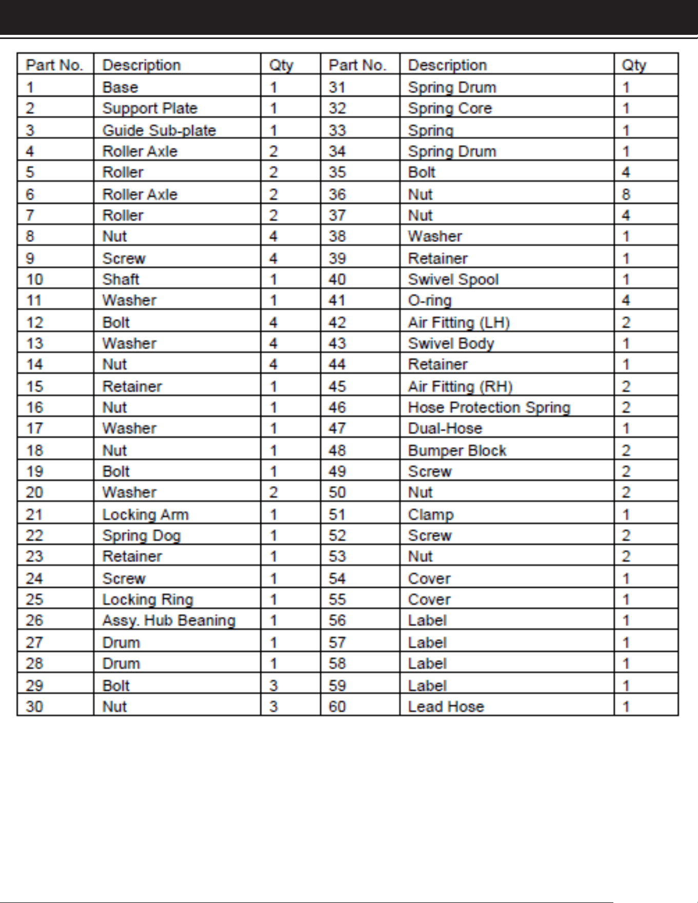
Draw a rectangular template with 1/2” holes on center with a length of 6-1/4” and a width 7-1/8”. Before drilling
match your template with the holes on the Base (1). Pre-drill the holes. Secure the Base (1) to the mounting
surface with four 1/2” lag bolts (not included). Refer to FIGURE 2.
When mounting on a wall, position these open holes On the
lower side (closest to the ground)

OPERATION OPERATION / MAINTENANCE
4
OPERATING THE HOSE REEL
1. Slowly pull out the Dual-Hose (47). You will hear a clicking noise
2. To latch or lock the Dual-Hose in place, pull it out at least 2 clicks, and then slowly allow it to retract to the
previous click.
3. To unlatch or unlock the Dual-Hose, slowly pull the Dual-Hose until the clicking noise stops completely, then
allow it to slowly and completely retract into the Hose Reel.
Never allow the Dual-Hose to retract quickly and without restraining the recoil speed.
Never let go of the end of the Dual-Hose when it is rewinding.
MAINTENANCE
WARNING!! Always SHUT OFF and disconnect the gas tanks and regulators , and purge all gases from the
system before attempting any maintenance.
Note: Always wear ANSI approved safety goggles during maintenance and make sure the Hose Reel is not
connected to the acetylene tank and/or oxygen tanks.
1. Pull out 6 feet of Hose (47) and allow the Drum (27,28) to latch.
2. Remove the Bumper Blocks (48) by taking out the Screws (49) and Nuts (50).
3. Feed the Dual-Hose back through the Support Plate (2).
4. To increase Hose tension, wrap the pulled Hose one time around the Drum (27,28). To decrease tension,
unwrap the Hose one wrap from the Drum (27,28).
5. Reinsert the Dual-Hose through the Support Plate (2) and reinstall the Bumper Blocks (48) by replacing the
Screws (49) and Nuts (50).
6. Check the tension by pulling out the Dual-Hose and releasing it.
HOSE REPLACEMENT
WARNING: Replace the Dual-Hose only with hoses intended for oxygen and acetylene welding.
1.
Remove the Support Plate by removing the Bolts (12).
2. Remove the Clamp (51) that attaches the Dual-Hose to the Drum (28). Detach the Dual-Hose from the
outlets (See FIGURE 1, page 5). Remove both Hose Protection Springs (46).
3. Remove the old hose and remove the Bumper Blocks (48). as explained above.
4. Feed the new hose through the guide on the Support Plate (2) and the cut out on the Drum (27,28) ange.
Replace the Hose Protection Springs (46) and connect the hose to the outlets. Make sure to apply thread
sealant or tape (not included) to the outlets threads. Reinstall the Clamp (51) and Bumper Blocks (48).
5. Carefully and slowly, release the Drum by gently pulling then releasing the locking ratchet. Then, slowly allow
the Dual-Hose to retract onto the reel.
ADJUSTING SPRING TENSION
7. If necessary, reposition the Bumper Blocks (48) by taking out the Screws (49) and Nuts (50), changing their
position, and replacing the Screws (49) and Nuts (50).
OPERATION
5
PARTS LIST
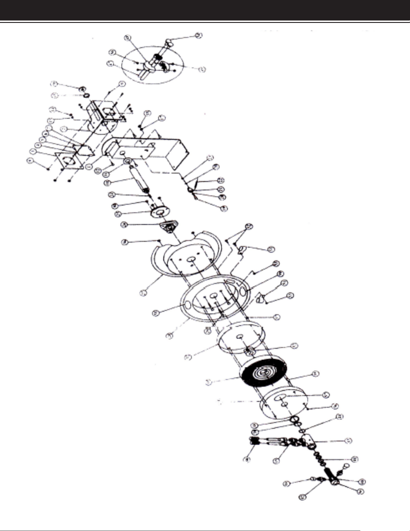
PARTS LIST PARTS DIAGRAM
6
DISCLAIMER
7
PLEASE READ THE FOLLOWING CAREFULLY
THE MANUFACTURER AND/OR DISTRIBUTOR HAS PROVIDED THE PARTS LIST AND ASSEMBLY
DIAGRAM IN THIS MANUAL AS A REFERENCE TOOL ONLY. NEITHER THE MANUFACTURER OR
DISTRIBUTOR MAKES ANY REPRESENTATION OR WARRANTY OF ANY KIND TO THE BUYER THAT HE
OR SHE IS QUALIFIED TO MAKE ANY REPAIRS TO THE PRODUCT, OR THAT HE OR SHE IS QUALIFIED
TO REPLACE ANY PARTS OF THE PRODUCT. IN FACT, THE MANUFACTURER AND/OR DISTRIBUTOR
EXPRESSLY STATES THAT ALL REPAIRS AND PARTS REPLACEMENTS SHOULD BE UNDERTAKEN
BY CERTIFIED AND LICENSED TECHNICIANS, AND NOT BY THE BUYER. THE BUYER ASSUMES
ALL RISK AND LIABILITY ARISING OUT OF HIS OR HER REPAIRS TO THE ORIGINAL PRODUCT OR
REPLACEMENT PARTS THERETO, OR ARISING OUT OF HIS OR HER INSTALLATION OF REPLACEMENT
PARTS THERETO.
Record Product’s Serial Number Here:
Note: If product has no serial number, record month and year of purchase instead.
Note: Some parts are listed and shown for illustration purposes only and are not available
individually as replacement parts.
MADE IN CHINA