OWNER’S MANUAL AND SAFETY INSTRUCTIONS
AIR HOSE REEL
ITEM # 43550 50’ X 3/8”, 43551 100’ X 3/8”, 43553 50’ X 1/2
SAVE THIS MANUAL. KEEP THIS MANUAL FOR SAFETY WARNINGS, PRECAUTIONS, ASSEMBLY,
OPERATION, INSPECTION, MAINTENANCE AND CLEANING PROCEDURES. WRITE THE PRODUCT’S
SERIAL NUMBER ON THE BACK OF THE MANUAL, OR THE MONTH AND YEAR OF PURCHASE IF
PRODUCT HAS NO SERIAL NUMBER
FOR QUESTIONS, PLEASE CALL CUSTOMER SERVICE: 909.628.0880

SAFETY WARNINGS
Read all safety warnings and instructions. Failure to follow the warnings and instructions may result in
injury and/or property damage. Save all warnings and instructions for future reference.
The warning and safety instructions in this manual are not meant to cover all possible conditions and
situations that may occur. Common sense, caution and care must be exercised when operating or
cleaning tools and equipment. Always contact your dealer, distributor, service agent or manufacturer
about problems or conditions you do not understand before operating the product.
Keep the work area clean and well lit. A cluttered work area may cause accidents. Never allow children to
use this product. When operating this product, keep children and animals at a safe distance from the work
area.
When not in use, store product in a secure, dry and safe place. The storage area should be out of the reach
of children. Never use the hose for anything other than its intended purpose. Maintain this product with care.
DO NOT exceed maximum operating pressure of 300PSI for your model hose reel.
Use proper eye protection when assembling and using the hose reel.
Use soap and water when checking for leaks.
WARNING: Exposure of skin directly to pressurized air or uid could result in severe bodily injury.
Be aware of all power lines, electrical circuits, water pipes and other mechanical hazards in your work area,
particularly those hazards below the work surface hidden from the operator’s view that may be unintentionally
contacted and may cause personal harm or property damage.
Be alert of your surroundings. Using this hose reel in conned work areas may put you dangerously close to
cutting tools and rotating parts.
Do not modify this product in any way. Unauthorized modication may impair the function and/or safety and
could aect the life of the equipment. There are specic applications for which this product was designed.
Always check for damaged or worn out parts before using this hose reel. Broken parts will aect the operation.
Replace or repair damaged or worn parts immediately.
Mount the hose reel on a surface capable of supporting the hose reel and its maximum load.
SAVE THESE WARNINGS.
1
SAFETY WARNINGS PARTS INFORMATION
SAVE THESE WARNINGS.
1 2
INSTALLATION
3
NOTE: Mounting hardware is not included and must be purchased separately. Decide forst where the reel will
be mounted before purchasing hardware. Dierent mounting positions require dierent types of hardware.
INSTALLING THE HOSE REEL
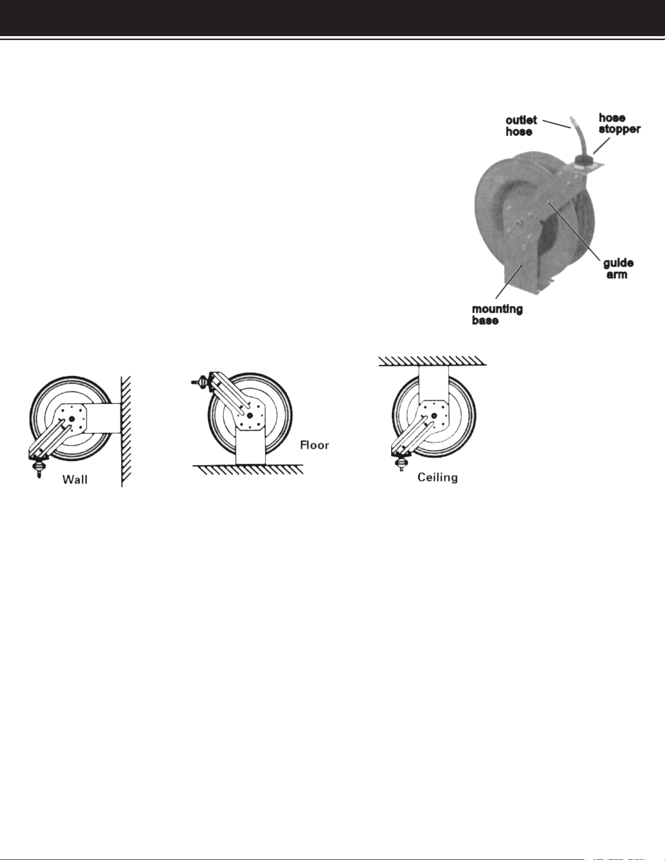
The reel can be mounted on the oor, ceiling or wall. Wherever it is convenient.
When choosing a location, remember that you can only mount the reaal to a
load bearing structural member capable of supporting the combined weight
if the reel, hose and forces caused by pulling or manuevering the hose.
Generally, mounting the reel near an air compressor is best since you can
connect the two with a shorter, less expensive length of the hose. Also, the air
compressor controls will be nearby for convenient adjusting.
Once youhave located a mounting spot, consult the “Typical mounting Position”
xhart below and choose the diagram that most closely matches your mounting
position. If necessary, adjust the guide arm
TYPICAL MOUNTING POSITIONS
ADJUSTING THE GUIDE ARM
1. Pull out 3 to 4 feet of hose and allow reel to a locked position.
2. Remove the four bolts connecting the guide arm to the support post.
3. Rotate the guide arm in 90 degree increments to the desired postion. Replace the 4 bolts and tighten.
Continue by choosing the proper mounting hardware. Mount the reel using four 1/2” bolts secured through the
four slots in the mounting base. Use washers on the mounting blts to help bear the weight of the reel.
After the reel is secured in position, attach the air hose coming from the compressor. Wrap threads of the male
connector onto the incoming air hose with teon tape (included) or threaf sealant and connect to the air inlet
valve on the side of the hose reel. Connect the other end of th eincoming air hose to the air compressor. Apply
teon tape the the threads on the hose before attaching the air tool
ADJUSTING THE GUIDE ARM
The hose stopper determines the length of the hose that remains outside the reel. To adust, pull the hose out
past the desired position of the hose stopper and latch reel. Loosen both stopper bolts and move the stopper
to the proper postion. Tighten the stopper bolts.

INSTALLATION OPERATION
4
OPERATING THE HOSE REEL
1. Slowly pull the hose reel to desired length. A ratcheting mehanism inside the reel makes a short series of
clicking sounfs every revolution of the reel.
2. To lock the real into postion, listen for the clicking sounds as the hose is slowlyy oulled from the reel. When
the reel clicks, stop pulling the hose. Decrease tension on the hose and the reel will lock into postion.
3. To retract the hose onto the reel, slowly pull out hose until you hear a series of clicking sounds stop. (1/8
revolution). DO NOT LET OF THE HOSE. Allow the hose to retract slowly until the hose stopper rests against
the hose guide.
4. Periodically check the hose for excessive wear and hose connection for leaks.
MAINTAINING THE HOSE REEL
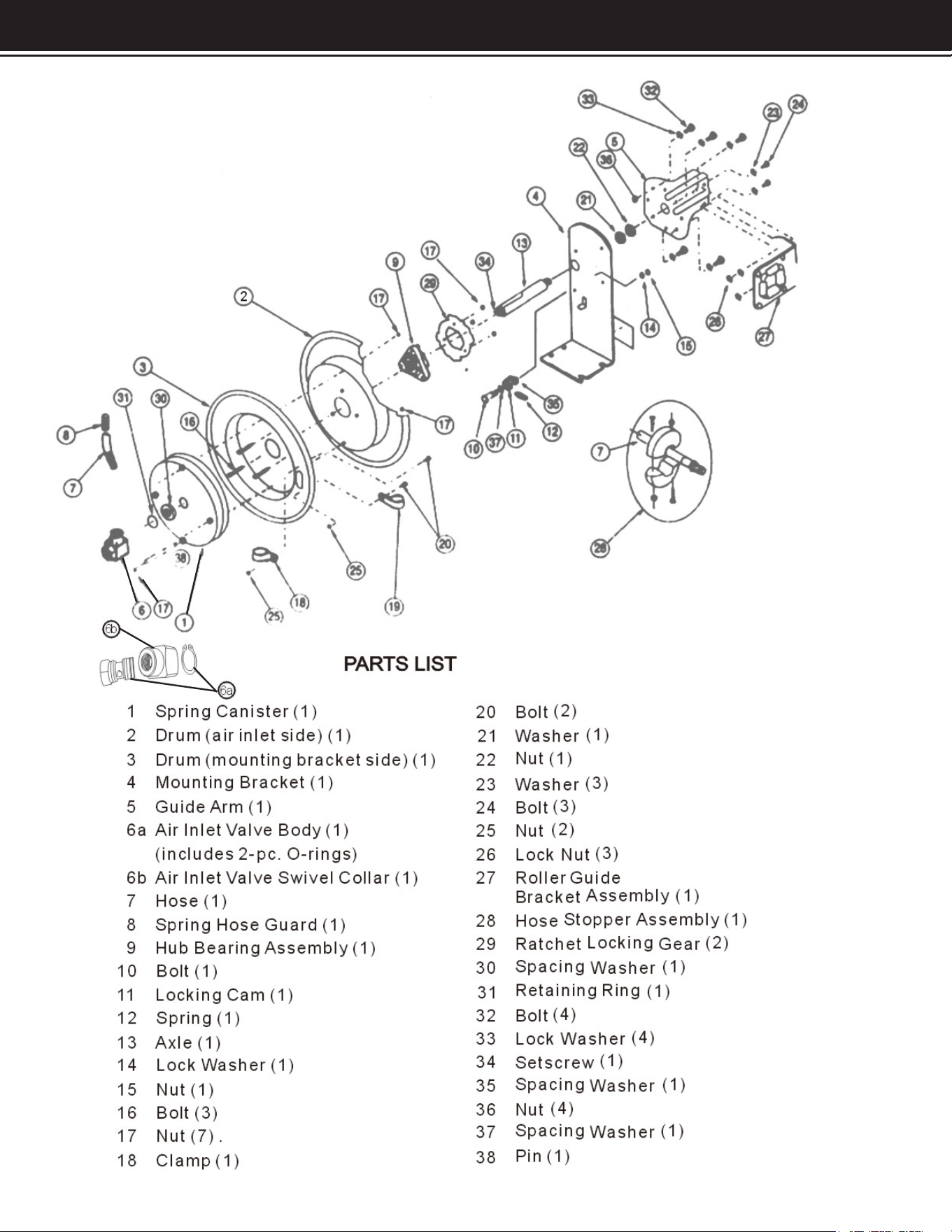
Refer to the parts diagram for part numbers
1. Disconnect the air supply and puul abut 2 feet of hose and latch the reel.
2. Remove the hose stopper.
3. While rmly holding onto the edge of the reel drum, unlatch the reel and carefully allow the drum to slowly
rewind drawing hose end back through the guide arm roller assembly abd onto the reel. Latch reel into position.
4. To increase tension: Unlatch the reel and turn clockwise, as viewed from the air inlet side. To decrease
tension: Unlatch and allow reel to rotate slowly counterclockwise, as viewed from the air inlet side.
5. Once the desired spring tension is reached, latch the reel into postion. Feed the hose end through the roller
assembly in the guide aem and reattach the hose stopper.
6. Connect the incoming air supply.
REPLACING AIR INLET VALVE O-RINGS
Refer to the parts diagram for part numbers.
1. Disconnect incoming air supply and inlet-end of hose from brass air inlet valve.
2. Unscrew air inlet valve assembly (6A & 6B) from axle shaft (13) by tting wrench onto hex portion of the valve
and turning counterclockwise.
3. Remove retaining ring (31) and slide air inlet valve swivel collar (6B) o from air inlet valve body (6A)
4. Remove worn O-rings (2pcs) and replace with new parts.
5. Reverse above procedure to reassemble.

OPERATION
5
4
REPLACING HOSE
1. Secure and stabilizing reel. In most cases, the hose can be replaced with reel still mounted.
2. Disconnect the incoming air supply.
3. Pull out entire length of the hose and lock reel. Make sure reel is securely locked in place.
4. Unscrew hose clamps that secure hose to drum. Disconnect the inlet end of the hose from the inlet valve
5. Pull inlet end of the hose through the slot in the drumand guide rollers, removing old hose completely.
6. Remove spring hose guard, hose clamp and hose stopper from old hose. Fit these parts on to a new hose
in identical positions.
7. Feed inlet end of the hose through the guide rollers and slot in drum.
8. Apply teon sealant tape or thread sealant to hose connector and connect to air inlet valve.
9. Attach the hose clamp tp drum. Rewind the hose onto the reel using normal operation.
REPLACING SPRING CANISTER
1. Follow steps 1-4 under “Adjusting Recoil Tension” above.
2. Unlatch reel and allow drum to slowly rewind completely until tension in spring is relieved and reel stops.
Carefully sontrol the speef of the drum. Do not release while rewinding.
3. Remove air inlet valve and spacing washer. Refer to “Replacing Air Inlet Valve O-rings: Step2”.
4. Remove nuts from mounting bracket side of the drum, inside drum cavity. Do not attemot to remove spring
canister nuts on air inlet side of the drum.
5. Pull entire apring canister (part 1) o the drum axle (13), replace with new spring canister.
6. Reverse above procedure to re-assemble.
7. After assembly, retension the reel by turning the drum three complete turns clockwise.
8. Feed hose through the guide arm and reattach hose stopper.
DISCLAIMER
6
PLEASE READ THE FOLLOWING CAREFULLY
THE MANUFACTURER AND/OR DISTRIBUTOR HAS PROVIDED THE PARTS LIST AND ASSEMBLY
DIAGRAM IN THIS MANUAL AS A REFERENCE TOOL ONLY. NEITHER THE MANUFACTURER OR
DISTRIBUTOR MAKES ANY REPRESENTATION OR WARRANTY OF ANY KIND TO THE BUYER THAT HE
OR SHE IS QUALIFIED TO MAKE ANY REPAIRS TO THE PRODUCT, OR THAT HE OR SHE IS QUALIFIED
TO REPLACE ANY PARTS OF THE PRODUCT. IN FACT, THE MANUFACTURER AND/OR DISTRIBUTOR
EXPRESSLY STATES THAT ALL REPAIRS AND PARTS REPLACEMENTS SHOULD BE UNDERTAKEN
BY CERTIFIED AND LICENSED TECHNICIANS, AND NOT BY THE BUYER. THE BUYER ASSUMES
ALL RISK AND LIABILITY ARISING OUT OF HIS OR HER REPAIRS TO THE ORIGINAL PRODUCT OR
REPLACEMENT PARTS THERETO, OR ARISING OUT OF HIS OR HER INSTALLATION OF REPLACEMENT
PARTS THERETO.
Record Product’s Serial Number Here:
Note: If product has no serial number, record month and year of purchase instead.
Note: Some parts are listed and shown for illustration purposes only and are not available
individually as replacement parts.
MADE IN CHINA
