OPERATOR’S MANUAL
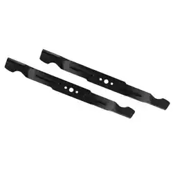
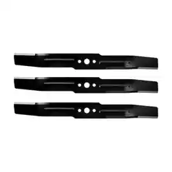
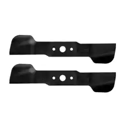
REPLACEMENT BLADES
MODEL NUMBER AB3000D
EGO Blade Set AB3000D is designed to be used with EGO POWER+ 30” lawn mower
LM3000SP/LM3000SP-FC and EGO COMMERCIAL 30” lawn mower LMX7600SP/
LMX7600SP-FC.
WARNING: Always protect your hands by wearing heavy gloves or wrapping the
cutting edges with rags or other materials when performing any maintenance on the
mower blades. Always remove the battery pack(s) when servicing or transporting the
mower.
NOTICE: The following tools (not included) are required for replacement of the blades:
◾
9/16 inch (14 mm) adjustable wrench (impact wrench with 9/16 inch (14 mm)
is recommended)
◾
9/16 inch (14 mm) torque wrench
◾
Manual screwdriver or metal rod with a diameter of 1/4 inch (6.35 mm) or less
◾
Manual screwdriver or metal rod with a diameter of 5/16 inch (8 mm) or less
REMOVING THE BLADES
1. Stop the motor, remove the battery
pack(s) and grass bag from the
mower.
2. Turn the mower on its side.
3. Insert a metal rod (stabilizer 1)
with a diameter of 5/16 inch
(8 mm) or less into the stabilizer
hole to prevent the blade from
rotating when loosening the bolt.
4. Use the 9/16 inch (14 mm) wrench
to turn the blade bolt COUNTERCLOCKWISE to loosen and remove the bolt
(Fig. 1).
NOTICE: If the bolt rotates with the motor shaft when loosening the bolt, place
another metal rod with a diameter less than 1/4 inch (6.35 mm) into the aligned holes
of the blade and fan to act as stabilizer 2.
5. Remove the outer flange and the
blade (Fig. 2).
6. Leave the fan on the motor shaft.
Be sure that the fan blade is
facing towards the deck (Fig. 2).
REPLACING THE BLADES
NOTICE: To re-install or replace the
blades, be sure to replace the parts
in the exact order in which they were
removed.
7. Position the blade onto the inner flange of the fan with the surface marked
“THIS SIDE FACING GRASS” facing toward the outside.
8. Align the outer flange with the shaft and assemble it in place.
COMMERCIAL
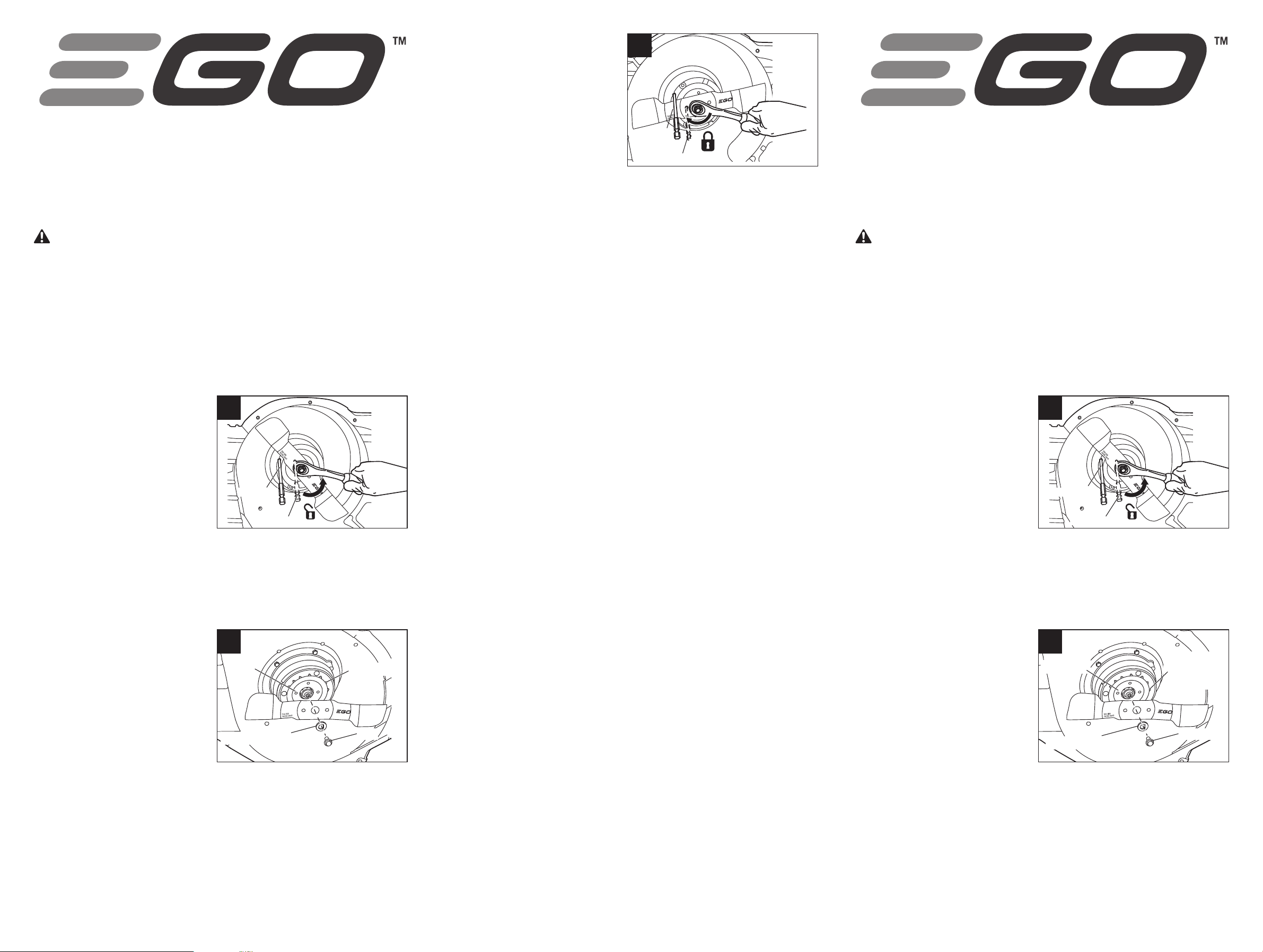
9. Mount the bolt into the shaft and
finger-tighten the bolt CLOCKWISE.
10. Insert the metal rod as shown in
Fig. 3.
11. Use the 9/16 inch (14 mm)
torque wrench to tighten the bolt
CLOCKWISE. The recommended
torque for the blade bolt is 36–43
ft-lb (50–60 N.m).
12. Repeat the process to replace the
second blade.
NOTICE: If the bolt rotates with the motor shaft when tightening the bolt, insert a
small metal rod with a diameter less than 1/4 inch (6.35 mm) to act as stabilizer 2.
1
Stabilizer 1
Stabilizer 2
3
Stabilizer 1
Stabilizer 2
2
Fan Blade
Fan
Bolt
Outer Flange
MODE D’EMPLOI
LAMES DE RECHANGE
MODÈLE N° AB3000D
Le jeu de lames EGO AB3000D est conçu pour être utilisé avec la tondeuse EGO
POWER+ de 30 po LM3000SP/LM3000SP-FC et la tondeuse EGO COMMERCIAL de 30
po LMX7600SP/LMX7600SP-FC.
AVERTISSEMENT: Protégez-vous toujours les mains en portant des gants
épais ou en enveloppant les bords coupants avec des chiffons ou d’autres matériaux
lorsque vous effectuez des opérations de maintenance sur la lame de la tondeuse à
gazon. Retirez toujours le(s) bloc(s)-piles lorsque vous effectuez une opération d’en-
tretien ou lorsque vous transportez la tondeuse à gazon.
AVIS: Les outils suivants (non inclus) sont nécessaires pour remplacer les lames:
◾
Clé réglable de 14 mm / 9/16 po (une clé à chocs avec une douille de 14 mm /
9/16 po est recommandée)
◾
Clé dynamométrique de 14 mm / 9/16 po
◾
Tournevis manuel ou tige en métal d'un diamètre de 6,35 mm / 1/4 po ou moins
◾
Tournevis manuel ou tige en métal d'un diamètre de 8 mm / 5/16 po ou moins
RETRAIT DES LAMES
1. Arrêtez le moteur, puis retirez le(s)
bloc-piles et le sac à herbe de la
tondeuse à gazon.
2. Mettez la tondeuse sur son côté.
3. Insérez une tige en métal
(stabilisateur 1) de 8 mm / 5/16
po de diamètre ou moins dans
le trou du stabilisateur pour
empêcher la lame de tourner
lorsque l'on desserre le boulon.
4. Utilisez la clé de 14 mm / 9/16 po pour faire tourner le boulon de la lame DANS
LE SENS INVERSE DES AIGUILLES D'UNE MONTRE afin de desserrer et de retirer
le boulon (Fig. 1).
AVIS: Si le boulon tourne avec l’arbre du moteur pendant que vous êtes en train
de le desserrer, placez une autre tige
en métal de diamètre légèrement
inférieur à 6,35 mm / 1/4 po à l’intérieur
des trous alignés de la lame et du
ventilateur pour servir de stabilisateur 2.
5. Retirez la rondelle extérieure et la
lame (Fig. 2).
6. Laissez le ventilateur sur l’arbre
du moteur. Assurez-vous que la
lame du ventilateur est orientée
vers le châssis (Fig. 2).
REMPLACEMENT DES LAMES
AVIS: Pour réinstaller ou remplacer les lames, assurez-vous que toutes les pièces
sont remises en place dans l’ordre exact dans lequel elles avaient été retirées.
COMMERCIAL
1
Stabilisateur 1
Stabilisateur 2
2
Pale du
ventilateur
Ventilateur
Boulon
Flasque extérieur
7. Positionnez la lame sur la bride de
fixation intérieure du ventilateur,
la surface de la lame sur laquelle
figure la mention «THIS SIDE
FACING GRASS» (Ce côté face
à l’herbe) étant orientée vers
l'extérieur.
8. Alignez la rondelle extérieure sur
l’arbre et assemblez-la en place.
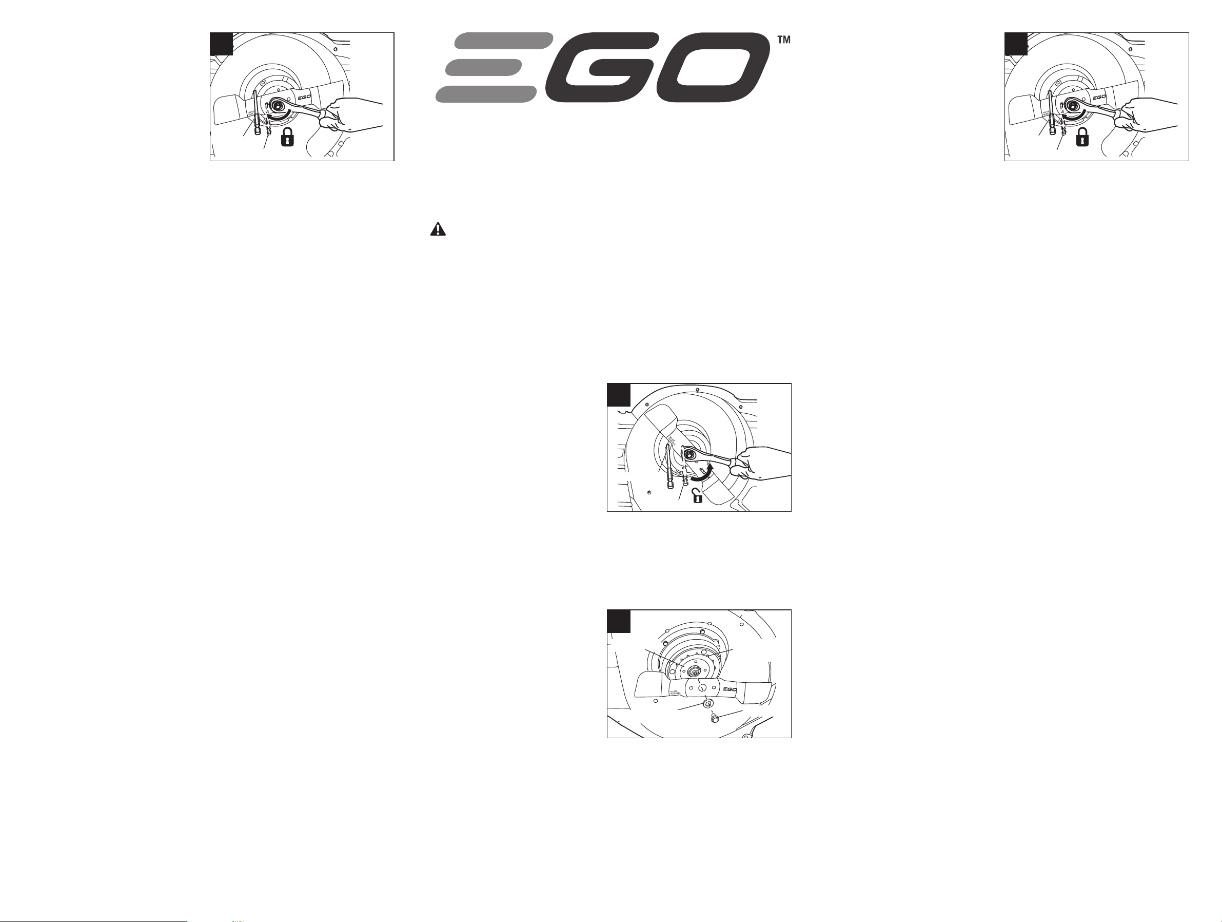
9. Montez le boulon dans l’arbre et
serrez le boulon à la main DANS LE SENS DES AIGUILLES D’UNE MONTRE.
10. Insérez la tige en métal comme illustré à la Fig. 3.
11. Utilisez une clé dynamométrique de 14 mm / 9/16 po pour serrer le boulon
DANS LE SENS DES AIGUILLES D’UNE MONTRE. Le couple recommandé pour le
boulon de fixation de la lame est de 50-60 Nm / 36-43 pi-lb.
12. Répétez l’opération pour remplacer la deuxième lame.
AVIS: Si le boulon tourne avec l’arbre du moteur pendant que vous êtes en train de
le serrer, placez une autre tige en métal de diamètre légèrement inférieur à 6,35 mm
/ 1/4 po pour servir de stabilisateur 2.
3
Stabilisateur 1
Stabilisateur 2
MANUAL DEL OPERADOR
CUCHILLAS DE REPUESTO
NÚMERO DE MODELO AB3000D
El conjunto de cuchillas EGO AB3000D está diseñado para utilizarse con la cortadora
de césped EGO POWER+ de 30 pulgadas LM3000SP/LM3000SP-FC y la cortadora
de césped EGO COMMERCIAL de 30 pulgadas LMX7600SP/LMX7600SP-FC.
ADVERTENCIA: Protéjase siempre las manos poniéndose guantes gruesos o en-
volviendo los bordes de corte con trapos u otros materiales cuando realice cualquier
mantenimiento en las cuchillas de la cortadora de césped. Retire siempre el paquete
(los paquetes) de batería cuando haga servicio de ajustes y reparaciones de la corta-
dora de césped o la transporte.
AVISO: Las siguientes herramientas (no incluidas) son necesarias para reemplazar
las cuchillas:
◾
Llave de tuerca ajustable de 9/16 de pulgada (14 mm) (se recomienda una llave
de impacto con 9/16 de pulgada [14 mm])
◾
Llave de torsión de 9/16 de pulgada (14 mm)
◾
Destornillador manual o varilla metálica con un diámetro de 1/4 de pulgada
(6,35 mm) o menos
◾
Destornillador manual o varilla
metálica con un diámetro de 5/16
de pulgada (8 mm) o menos
DESINSTALACIÓN DE LAS CUCHILLAS
1. Pare el motor y retire el paquete
(los paquetes) de batería y la
bolsa de pasto de la cortadora de
césped.
2. Voltee la cortadora de césped
sobre uno de sus lados.
3. Inserte una varilla metálica (estabilizador 1) con un diámetro de 5/16 de
pulgada (8 mm) o menos en el agujero para el estabilizador con el fin de
impedir que la cuchilla rote al aflojar el perno.
4. Utilice la llave de tuerca de 9/16 de pulgada (14 mm) para girar el perno de la
cuchilla EN SENTIDO CONTRARIO AL DE LAS AGUJAS DEL RELOJ con el fin de
aflojar y retirar el perno (Fig. 1).
AVISO: Si el perno rota con el eje del
motor al aflojar el perno, coloque otra
varilla metálica con un diámetro de
menos de 1/4 de pulgada (6,35 mm)
en los agujeros alineados de la cuchilla
y el ventilador para que actúe como
estabilizador 2.
5. Retire la brida externa y la cuchilla
(Fig. 2).
6. Deje el ventilador en el eje
del motor. Asegúrese de que la paleta del ventilador esté orientada hacia la
plataforma (Fig. 2).
REEMPLAZO DE LAS CUCHILLAS
AVISO: Para reinstalar o reemplazar las cuchillas, asegúrese de reinstalar las piezas
en el orden exacto en que fueron retiradas.
7. Posicione la cuchilla sobre la brida interna del ventilador con la superficie
marcada con las palabras “THIS SIDE FACING GRASS” (ESTE LADO
ORIENTADO HACIA EL PASTO) orientadas hacia fuera.
COMMERCIAL
8. Alinee la brida externa con el
eje y realice el ensamblaje en la
posición correcta.
9. Monte el perno en el eje y
apriételo con los dedos EN EL
SENTIDO DE LAS AGUJAS DEL
RELOJ.
10. Inserte la varilla metálica de la
manera mostrada en la Fig. 3.
11. Utilice la llave de torsión de 9/16
de pulgada (14 mm) para apretar el perno EN EL SENTIDO DE LAS AGUJAS DEL
RELOJ. La fuerza de torsión recomendada para el perno de la cuchilla es de 36-
43 pies-lb (50-60 Nm).
12. Repita el proceso para reemplazar la segunda cuchilla.
AVISO: Si el perno rota con el eje del motor al apretar el perno, inserte una varilla
metálica pequeña con un diámetro de menos de 1/4 de pulgada (6,35 mm) para que
actúe como estabilizador 2.
1
Estabilizador 1
Estabilizador 2
3
Estabilizador 1
Estabilizador 2
2
Paleta del
ventilador
Ventilador
Perno
Brida externa
1-855-EGO-5656 (1-855 -346-5656)
EGOPOWERPLUS.COM
EGO Customer Service
769 Seward Ave NW #102
Grand Rapids, MI 49504
09/2025