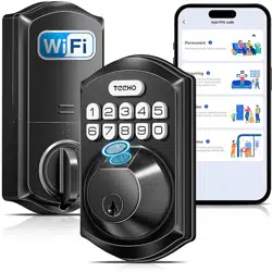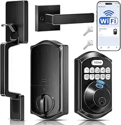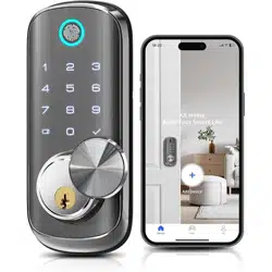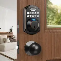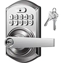
Wi-Fi Keypad Fingerprint Smart Lock
Installation Guide / Quick Start Guide
Thank you for purchasing our products. Please review this manual thoroughly before operating your device.
All pictures in this manual are for illustration purpose only. Actual product may vary due to product upgrade.
3
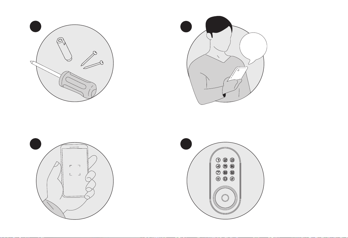
Register and Log in App,
add device by scanning
QR code on the device.
Calibrate the smart lock
and complete bluetooth
& Wi-Fi setting in the
App.
2
1
Following the
installation instruction
to install the smart
lock.
4
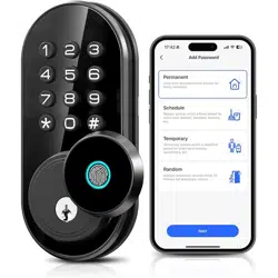
Scan QR code to download
App
App
Quick Start Guide
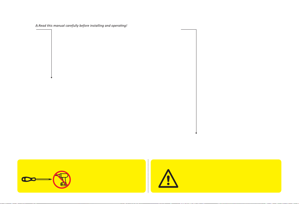
IMPORTANT:
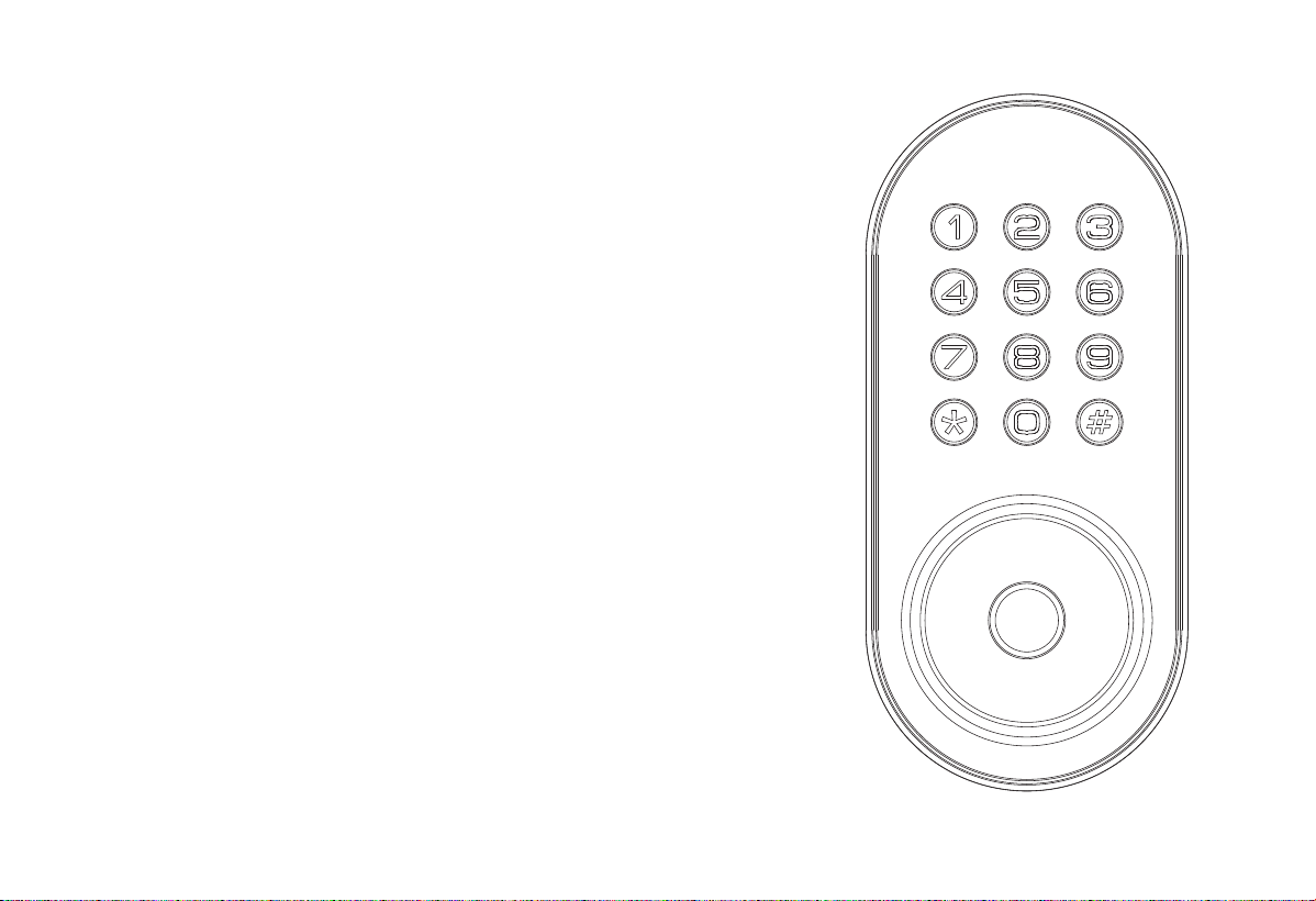
TOOL REQUIRED:
Do not use an electric
screwdriver during installation.
Do not load batteries until lock is
completely installed.
Installation Guide
STEP 1: Prepare the door and check dimensions
STEP 2: Install the latch and strike
STEP 3: Install exterior assembly
STEP 4: Install interior assembly
P8
P 9
P 10
P 11
P 12
P 14
P 15
P 16
P17
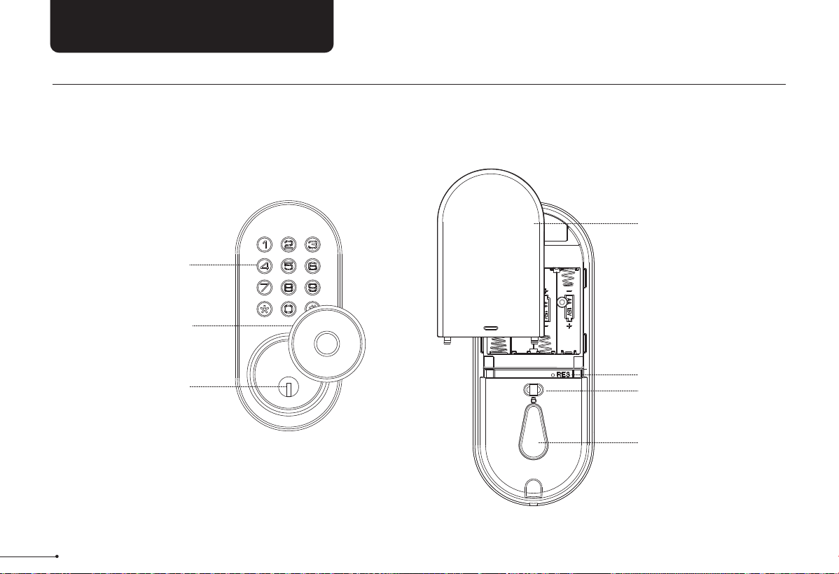
At a Glance
How to Lock/Unlock
Definitions
Code Format
Quick Set Up
Factory Default Settings
Download App
Troubleshooting
FCC Statement & Warnings
P 3
P 4
P 6
P 7
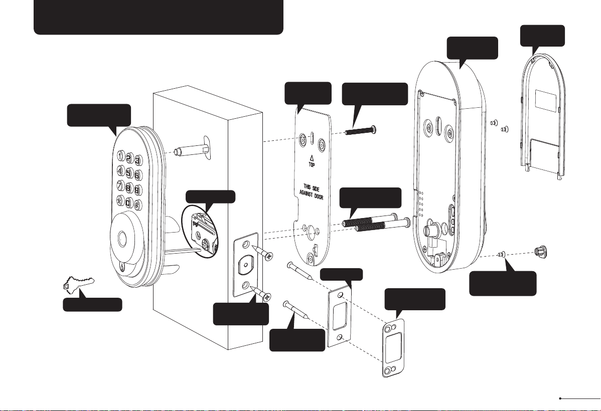
INSTALLATION OVERVIEW
Backup key (A)
Mounting
plate Screws (J)
Mounting
plate (E)
Interior
Assembly (G)
Exterior Assembly
Screw
(F)
Exterior Assembly
(B)
Latch (C)
Strike (D)
Reinforcement
plate (D-1)
Strike Screws
(H)
Latch Screws
(I)
Interior Assembly
Screws (K)
Battery
Cover (L)
1
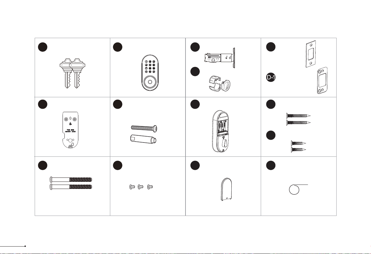
Parts List
If any parts are missing or damaged, please contact Customer Support.
Latch x1
Strike x1
Exterior Assembly x1
Mounting Plate x1 Strike Screws x2
Mounting plate Screws x2
Interior Assembly
Screws x3
Latch Screws x2
A B C
Drive-In Collar (Optional)
C-1
E F G
H
I
J K
D
Battery Cover x1
L
Backup Key x2
Reinforcement
Plate x1
(optional)
Interior Assembly x1
⅜
¾
2 2
Exterior Assembly
Screw (Optional)
(35mm<door thickness<50mm)
2
M
Reset Tool x1
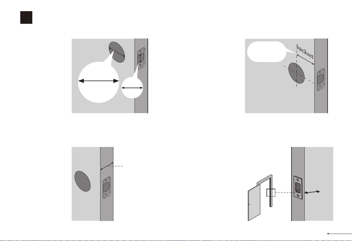
Measure to confirm
that the hole in the
door edge is 1"
(25mm).
Measure to confirm
that the backset is
either 2-3/8" or
2-3/4" (60 or 70mm)
2-3/8" or 2-3/4"
(60 or 70mm)
Make sure the hole in
the door frame is
drilled a minimum of 1’’
(25mm) deep, to leave
enough space for the
deadbolt to extend into
the door frame when
the door is locked.
Measure to confirm
that the door is 1-3/8"
to 2" (35 mm to
50mm) thick.
A
Measure to
confirm that the
hole in the door is
1-1/2’’ or 2-1/8"
(38mm or 54mm)
B
C
D
Prepare the door and check dimensions
1
STEP
1"
25mm
1-3/8" to 2"
(35mm to 50mm)
Make sure the door frame is aligned with the door.
There are no obstructions stuck in the door frame.
Notes:
1-1/2" or 2-1/8"
(38 or 54mm)
1"
25mm
3
chiseled
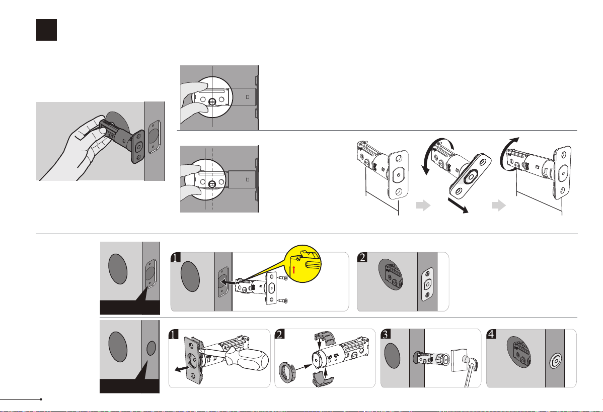
Install the latch and strike
2
STEP
Hold the latch in front of the door hole,
with the latch face flush against the
door edge. Is the slotted hole centered
in the door hole?
No adjustment is required.
Proceed to next step.
Slotted hole is
NOT centered.
A
B
YES
NO
Rotate and pull the
latch as shown to
extend latch.
Determine backset
and adjust the latch
Install the latch
Latch Screws (I)
up
4
2-3/4"
(70mm)
2-3/8"
(60mm)
pull
Drive-In
Collar(C-1)
C
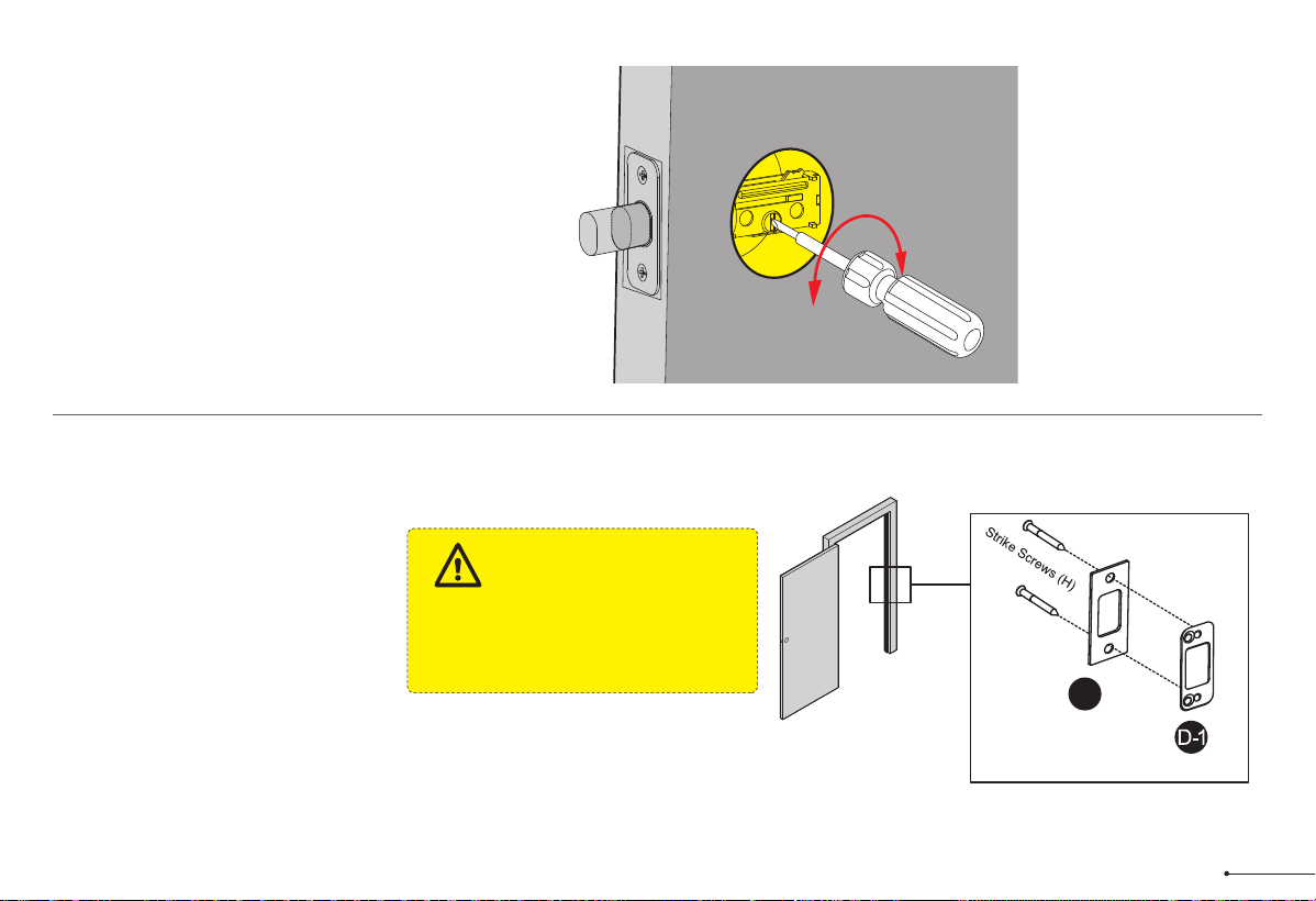
Use a screwdriver to test if
deadbolt works smoothly.
D
Install strike on the door frame.
Make sure the hole in door frame is
drilled a minimum of 1" (25mm)
deep.
IMPORTANT:
D
(Optional)
5
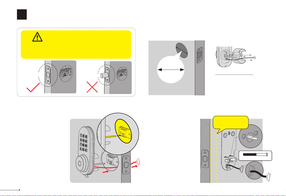
Install exterior assembly
3
STEP
Unlocked
Before installation, make sure the latch is fully
retracted (in the unlocked position)
IMPORTANT:
Locked
B
With the latch fully
retracted (in the
unlocked position),
route the cable below
the latch, and insert
the tailpiece through
the slot in the latch.
C
Secure the mounting
plate with the supplied
screws. Do not over
tighten screws.
Remove the spacer
Proceed to next step
A
1-1/2" (38mm)
2-1/8" (54mm)
Measure the diameter of
the hole in the door.
1-1/2" or 2-1/8"
(38 or 54mm)
Tailpiece
Mounting plate Screws(J)
Keep parallel to
door edge.
6
C
Keep the thumb turn in vertical position
and install the interior assembly.
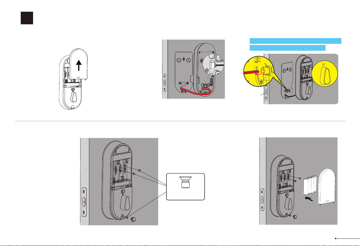
Install interior assembly
4
STEP
Push the battery
cover out in the
direction as
illustrated.
Insert the cable
into the connector.
Push the
connector in firmly
until it is
completely
attached.
A B
Attach Interior
Assembly to
Mounting Plate and
tighten 3 Screws.
D
Horizontal
Unlocked
Interior Assembly
Screws (K)
Load 4 AA (1.5V)
batteries (Not included)
into the battery
compartment.
E
7
QUICK START GUIDE
At a Glance
Exterior Assembly Interior Assembly
Keypad
Keyhole
Keyhole Cover
Battery Cover
Reset Button
Multifunction Button
Thumb Turn
8
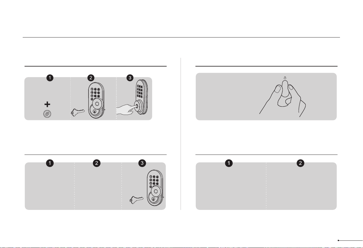
How to Lock / Unlock
UNLOCK the door from outside
LOCK the door from outside
LOCK the door from inside
Key Lock
UNLOCK the door from inside
Rotate the thumb turn to
Unlock position.
Auto Lock Mode
In Auto Lock mode,
the latch bolt is
automatically
extended after
unlocking.
Manual Mode
Press any button
on the keypad for 2
seconds to lock the
door in manual
mode
Auto Lock Mode
In Auto Lock mode, the
device will be locked
automatically.
Master/User code
Manual Mode
Rotate the thumb
turn to the lock
position to lock the
device
9
• MASTER CODE
Required for programming and function settings. The master code
can be used to unlock the door in away mode and private mode. The
default master code must be changed before programming. The
owner/manager should keep this information confidential.
• AUTO LOCK
Automatically locks the latch 30 seconds after unlocking. This
function is disabled by default. You can set the time delay for
automatic locking between 10 and 180 seconds.
• WRONG CODE ENTRY LIMIT
After 10 unsuccessful attempts to enter a valid PIN code, the device
switches off for 3 minutes.
• AWAY MODE
This is a safety feature for you when you leave your house for
vacation or a long trip. When you activate the away mode, all user
codes and user fingerprints will be locked until the master code is
entered on the keypad. When the lock is unlocked by turning the
thumb or key, an alarm will sound for 1 minute. By entering the
master code on the keypad, you can disable the alarm and the away
mode.
• SILENT MODE
The sounds when pressing keypad can be muted. However, you will
still hear low battery warnings and system alerts.
• MULTIFUNCTION BUTTON
Push and hold the multifunction button on inside panel for 3 seconds
to activate privacy mode. This will disable all user PIN code access.
Privacy mode will be disabled automatically after unlock the door with
the thumb turn or master PIN code.
• LOW BATTERY ALARM
The batteries are getting low if the battery indicator keeps flashing .
Please replace with four new batteries for the best performance
(alkaline batteries only).
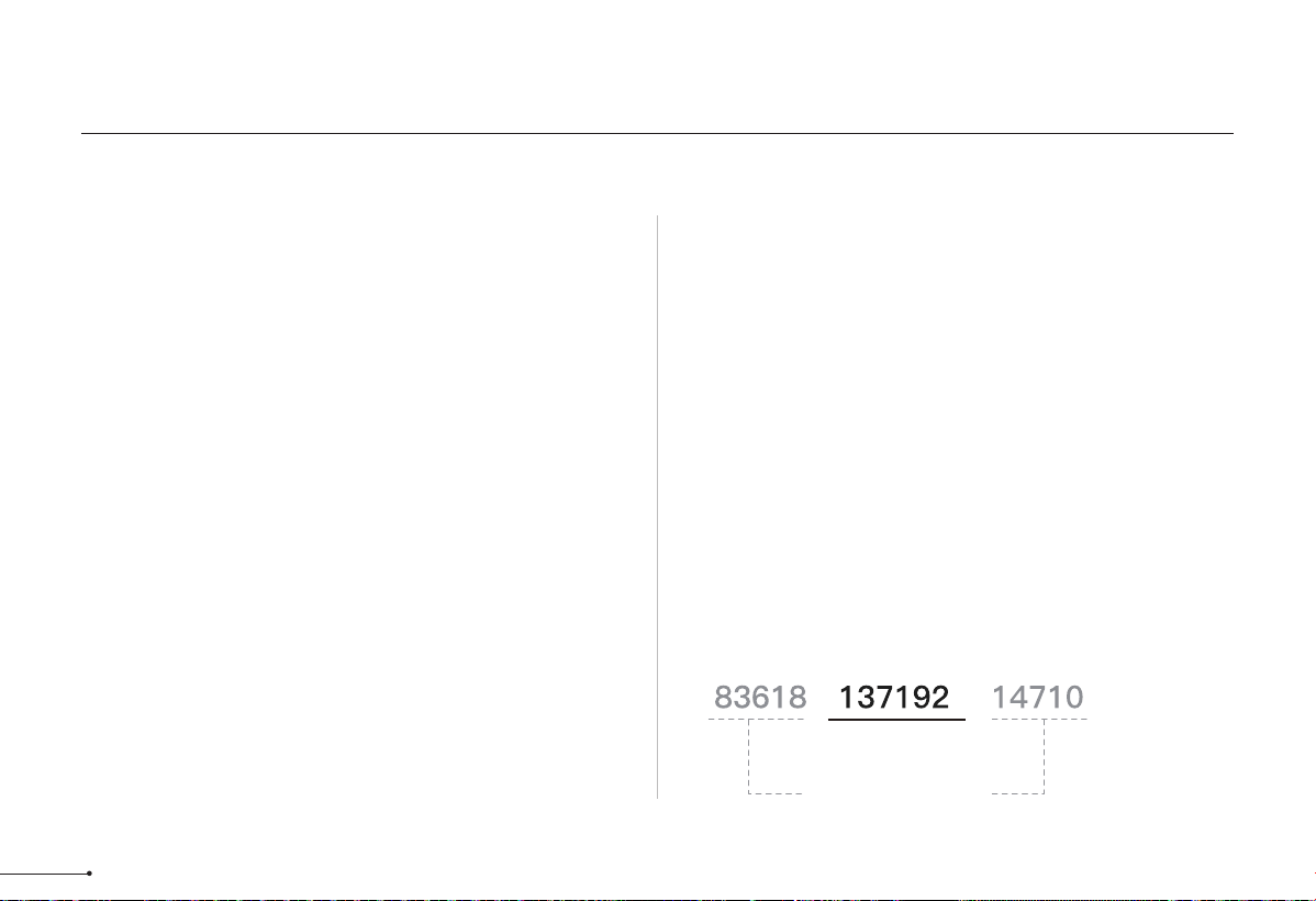
• UNLOCK WITH FAKE CODE
User can prevent pin code exposure from strangers by entering
random digits before or after pin code.
Definitions
PASSWORD
RANDOM DIGITS
10
1. Master Code(4 to 10 digits): The default Master Code is 12345678. It is required that you change it to a code of your
own before programming.
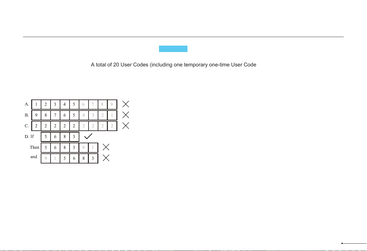
2. User Code (4 to 10 digits): A total of 20 User Codes (including one temporary one-time User Code) can be programmed
and stored.
3. Both Master Code and User Code don’t support the following combination of numbers.
Forward number sequence
Backward number sequence
Repeat number sequence
Contain existing code sequence
Programming Basic
Code Format
11
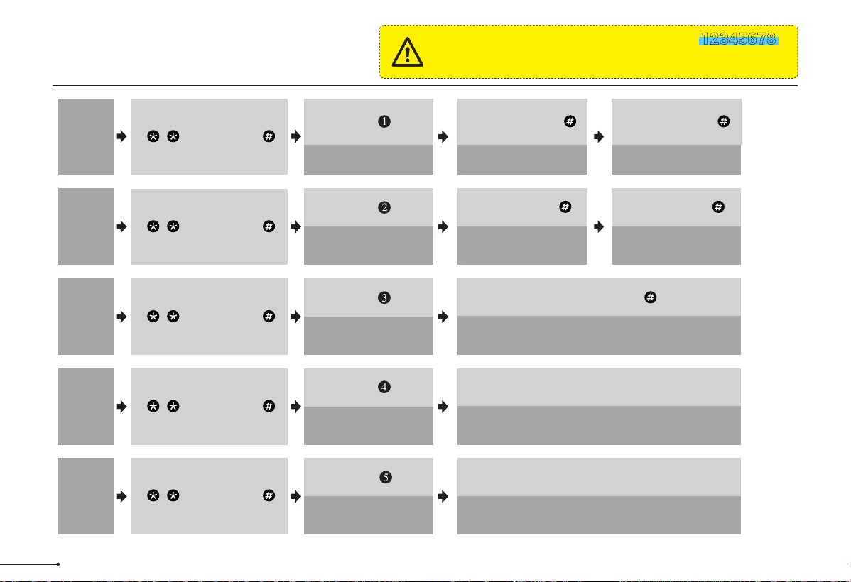
Quick Set Up
The default Master Code is 12345678 .
It is required that you change it to a code of
your own before programming.
IMPORTANT:
Delete
User
Code
Add
User
Code
Change
Master
Code
Press
Press
Press
Wait for green light flash
Wait for green light flash
Succeed
Green light flash
Succeed
Green light flash
Succeed
Green light flash
Wait for green light flash
Wait for green light flash
Wait for green light flash
Unwanted User Code +
Succeed Green light flash+A long beep
Wait for green light flash
Scan fingerprint 8 times each time
succeed with a short beep
Press
Add
User
Finger-
prints
Succeed Green light flash+A long beep
Wait for green light flash
Scan unwanted fingerprint 1 time
Delete
User
Finger-
prints
Press
+ Master Code +
+ Master Code +
+ Master Code +
+ Master Code +
+ Master Code +
New Master Code +
New Master Code +
New User Code +
New User Code +
12
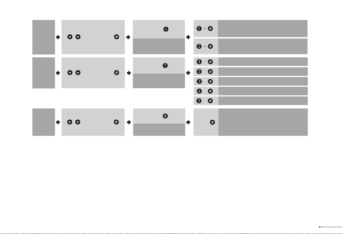
Notes:
1. Beeps only sound when the Silent Mode is disabled.
2. If the indicators flash red light, it means your setting failed and it will require to re-enter master mode if you would like to continue your programming.
Auto
Lock
Wait for green light flash
Press
Silent
Mode
Silent Mode Disabled
Green light flash
Silent Mode Enabled
Green light flash
Wait for green light flash
Press
Away
Mode
Wait for green light flash
Press
+ Master Code +
+ Master Code +
+ Master Code +
Auto Lock Disabled Green light flash
+
+
Auto Lock 30S Green light flash
Auto Lock 60S Green light flash
+
Auto Lock 120S Green light flash
+
Auto Lock 180S Green light flash
+
13
Away Mode Enabled
Press
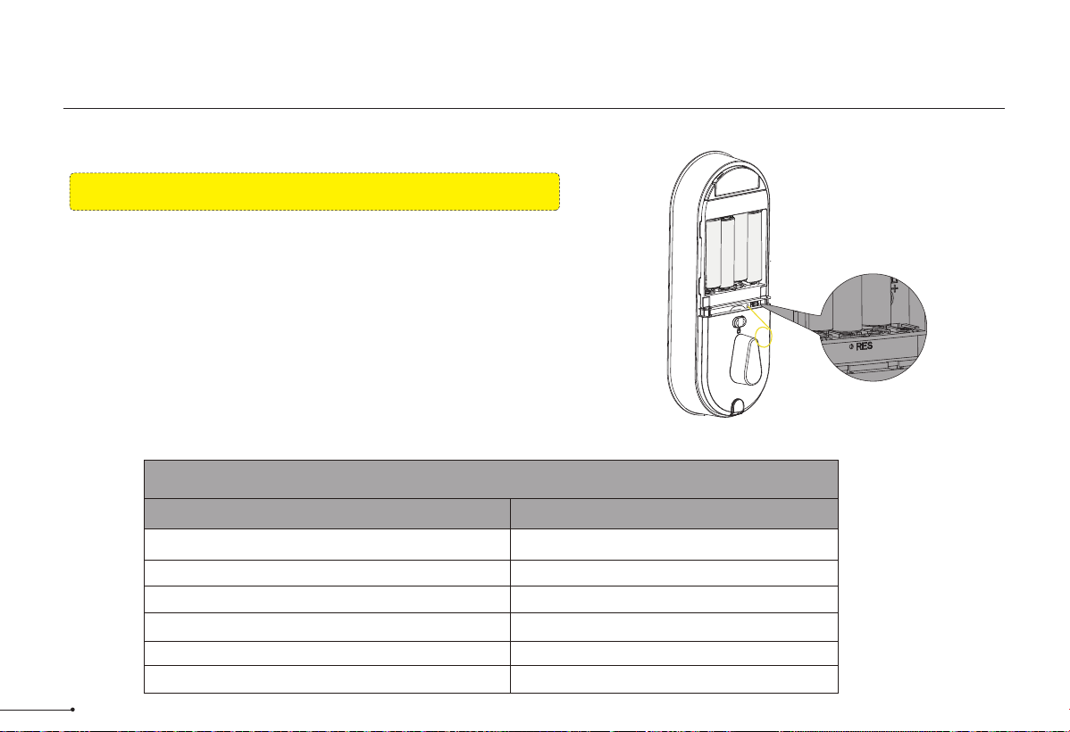
Factory Default Settings
Settings
Master Code
Auto Lock
Silent Mode
Wrong Code Entry Limit
Shutdown Time
Away Mode
Factory Defaut
12345678
Disabled
Disabled
10 times
3 mins
Disabled
Factory Default Settings
14
Resetting the device will delete all User PIN Codes and Master PIN Code stored
in the lock.
How to Reset?
Step 1. Keep the door open and the lock unlocked (thumb turn will be vertical).
Step 2. Using the Reset Tool, press and hold the Reset Button for 5 seconds until you
hear the "BEEP" and the latch rotates, turning the thumb turn to the vertical
position automatically.
Reset button
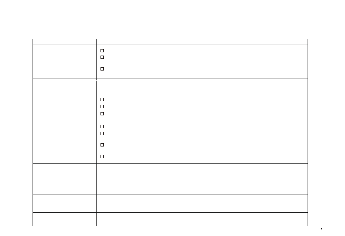
Troubleshooting
Problem
Solution
Check if the length of mounting screws is correct.
Make sure the backset on the latch is set to the proper length. Refer to Installation Guide
Make sure prior to installation latch bolt is retracted and key is not in lockset when installing the
deadbolt. Refer to Installation Guide
Please restore to factory setting and enter the default Master Code to set up the lock. Refer to
User Guide
The latch does not operate
correctly after installation.
Feel a bump while turning
the thumb turn or the key?
Keypad not responding.
Master Code can not be
changed.
I forgot my Master Codes.
Fingerprint can't unlock.
"Auto lock" does not
function.
Fail to set up the lock.
Please make sure that the lock is installed correctly.
Please insert fresh batteries and make sure that the cable is properly connected.
After installation, reset the lock to factory settings to complete the lock setting process.
Please refer to User Guide to restore factory settings and reprogram all codes.
Make sure the fingerprint is registered and recognizable.
Perform a reset to clear all PIN codes. Once the reset is complete, all PIN codes will be deleted
and the master code will be reset to the default master PIN code 12345678.
I
f the battery indicator blinks continuously, the batteries are weak. Please replace them with four
new batteries to get the best performance (alkaline batteries only).
Please refer to the USER GUIDE to activate the AUTO LOCK function.
Please make sure that the batteries are inserted correctly
If the battery indicator flashes continuously, the batteries are almost empty. Please replace them
with four new batteries for best performance (alkaline batteries only).
Please make sure that the cable is well connected to the connector and has not been damaged
during installation
Please make sure the lock has been set up and complete the lock handing determination.
15

This equipment has been tested and found to comply with the limits for a
Class B digital device, pursuant to part 15 of the FCC Rules. These limits
are designed to provide reasonable protection against harmful
interference in a residential installation. This equipment generates, uses
and can radiate radio frequency energy and, if not installed and used in
accordance with the instructions, may cause harmful interference to radio
communications. However, there is no guarantee that interference will not
occur in a particular installation. If this equipment does cause harmful
interference to radio or television reception, which can be determined by
turning the equipment off and on, the user is encouraged to try to correct
the interference by one or more of the following measures:
• Reorient or relocate the receiving antenna.
• Increase the separation between the equipment and receiver.
• Connect the equipment into an outlet on a circuit different from that to
which the receiver is connected.
• Consult the dealer or an experienced radio/TV technician for help.
Caution: Any changes or modifications to this device not explicitly
approved by manufacturer could void your authority to operate this
equipment.
This device complies with part 15 of the FCC Rules. Operation is subject
to the following two conditions: (1) This device may not cause harmful
interference, and (2) this device must accept any interference received,
including interference that may cause undesired operation.
RF Exposure Information
This equipment complies with FCC radiation exposure limits set forth for
an uncontrolled environment. This equipment should be installed and
operated with minimum distance 20cm between the radiator and your
body.
English:This device contains licence-exempt transmitter(s)/receiver(s) that
comply with Innovation, Science and Economic Development Canada’s
licence-exempt RSS(s). Operation is subject to the following two conditions:
(1) This device may not cause interference.
(2) This device must accept any interference, including interference that may
cause undesired operation of the device.
The digital apparatus complies with Canadian CAN ICES-3 (B)/NMB-3(B).
French: Cet appareil contient des émetteurs/récepteurs exempts de licence qui
sont conformes aux RSS exemptés de licence d'Innovation, Sciences et
Développement économique Canada.
L'exploitation est soumise aux deux conditions suivantes :
(1) Cet appareil ne doit pas provoquer d'interférences.
(2) Cet appareil doit accepter toute interférence, y compris les interférences
susceptibles de provoquer un fonctionnement indésirable de l'appareil.
l'appareil numérique du ciem conforme canadien peut - 3 (b) / nmb - 3 (b).
This device meets the exemption from the routine evaluation limits in section
2.5 of RSS 102 and compliance with RSS 102 RF exposure, users can obtain
Canadian information on RF exposure and compliance.
cet appareil est conforme à l'exemption des limites d'évaluation courante dans
la section 2.5 du cnr - 102 et conformité avec rss 102 de l'exposition aux rf, les
utilisateurs peuvent obtenir des données canadiennes sur l'exposition aux
champs rf et la conformité.
This equipment complies with Canada radiation exposure limits set forth for an
uncontrolled environment.
Cet équipement est conforme aux limites d'exposition aux rayonnements du
Canada établies pour un environnement non contrôlé.
This equipment should be installed and operated with minimum distance 20cm
between the radiator & your body.
Cet équipement doit être installé et utilisé à une distance minimale de 20 cm
entre le radiateur et votre corps.
FCC Statement ISED Statement
16

Warnings
Failure to follow the below instructions could result in damage to the
product and void the factory warranty.
This manufacturer advises that no lock can provide complete security by
itself.
This lock may be defeated by forcible or technical means, or evaded by
entry elsewhere on the property.
No lock can substitute for caution, awareness of your environment, and
common sense.
Product Care:
• This lockset is designed to provide the highest standard of product
quality and performance. Care should be taken to ensure a long-lasting
finish. When cleaning is required, use a soft, damp cloth. Using lacquer
thinner, caustic soaps, abrasive cleaners or polishes could damage the
coating and result in tarnishing.
• Avoid exposure to direct sunlight. Long-term exposure to direct sunlight
may damage the lock.
Do not install batteries until the lock is completely installed on door.
• User Pin Codes: Can be 4-10 digits and can be set up in App.
• Door sensor calibration: To calibrate your door, please follow the
instruction in App step by step. Once it’s calibrated successfully, you
could try detect the status of your door in App.
• Share your device: Share your device means that you share the access
to track the device with your other users, please be aware of the potential
risks it may cause.
17