
1
Quick Start Guide
DM10
Version: 1.1
Due to regular upgrades of systems and products, ZKTeco could not guarantee
exact consistency betweenthe actual product and the written information in this manual.
2
1
6
2
7
3
8
4
9
5
10
Appearance & Installation
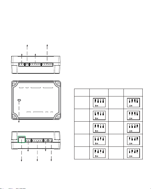
1.Appearance
Status of indicator
Normal communication: The indicator
flashes every two seconds.
Abnormal communication: The indicator
will glow constantly.
The indicator flashes rapidly within 30s
after the device is connected to the power
supply.
Address SwitchSettingAddressSwitchSetting
Indicator LED
1 2
3
4
1 2
3
4
1 2
3
4
1 2
3
4
1 2
3
4
1 2
3
4
1 2
3
4
1 2
3
4
1 2
3
4
1 2
3
4
DIPswitch
Power
EXTRS485
Auxiliary input
Wiegand reader
Lock
Auxiliary
output
12V o utput
Wiegand reader
PWR
NO
COM
NC
485A
485B
GND
BEEP
GLED
WD1
WD0
GND
12V
BEEP
GLED
WD1
WD0
GND
12V
GND
AUX
BUT
GND
SEN
NO
COM
NC
12VOUT
GND
12V
GND
RS485 ADD.
RS485
AUX IN
READER 1
READER 2
AUX OUT
LOCK VOUT
POWER
3
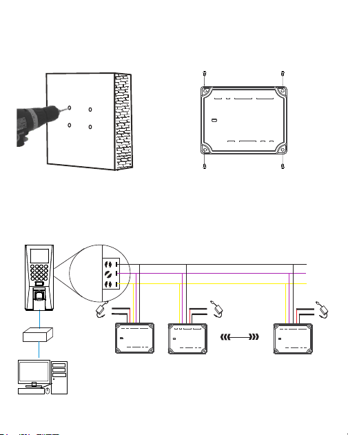
2.Installation
1)Drill holes on the wall 2)Fix the device with four screws
The DM10 has to be connected to F18(Master Device) to use the software.
An Access Controller can connect to a maximum of
eight DM10.
Each device requires a separate power supply.
GND
485+
485-
EXT
1
DC12V
-
+
-
+
DC12V
Router
Master DeviceConnection
2 8
GND
485A
485B
-
+
DC12V
PWR
NO
COM
NC
485A
485B
GND
BEEP
GLED
WD1
WD0
GND
12V
BEEP
GLED
WD1
WD0
GND
12V
GND
AUX
BUT
GND
SEN
NO
COM
NC
12VOUT
GND
12V
GND
RS485 ADD.
RS485
AUX IN
READER 1
READER 2
AUX OUT
LOCK VOUT
POWER
PWR
NO
COM
NC
485A
485B
GND
BEEP
GLED
WD1
WD0
GND
12V
BEEP
GLED
WD1
WD0
GND
12V
GND
AUX
BUT
GND
SEN
NO
COM
NC
12VOUT
GND
12V
GND
RS485 ADD.
RS485
AUX IN
READER 1
READER 2
AUX OUT
LOCK VOUT
POWER
PWR
NO
COM
NC
485A
485B
GND
BEEP
GLED
WD1
WD0
GND
12V
BEEP
GLED
WD1
WD0
GND
12V
GND
AUX
BUT
GND
SEN
NO
COM
NC
12VOUT
GND
12V
GND
RS485 ADD.
RS485
AUX IN
READER 1
READER 2
AUX OUT
LOCK VOUT
POWER
PWR
NO
COM
NC
485A
485B
GND
BEEP
GLED
WD1
WD0
GND
12V
BEEP
GLED
WD1
WD0
GND
12V
GND
AUX
BUT
GND
SEN
NO
COM
NC
12VOUT
GND
12V
GND
RS485 ADD.
RS485
AUX IN
READER 1
READER 2
AUX OUT
LOCK VOUT
POWER
4
Open the ZKAccess3.5 software, click [Device]> [New], enter the name
and IP address of F18 , andthenclick [OK].
Step 1
After proper wiring, please follow the below instructions.
1. Set the RS485 address of DM10 as 2-9.
2. Set the F18 serial port as ”host” ([COMM.]> [serial port]).
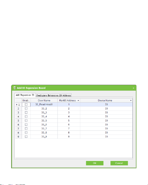
Quick Start
Click [More...] > [Add IO Expansion Board] , check the RS485 address of
DM10, andthenclick [OK].
Step 2
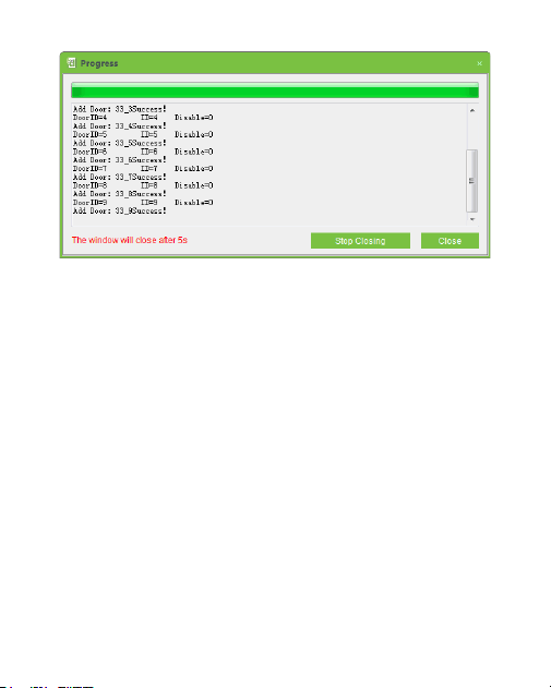
5
After successful configuration, the flashes every two 2 Indicator LED
seconds, indicating that the communication is normal. After adding
successfully, the parameters of the access control unit could be set, please
refer to the ZKAccess 3.5 user manual for further details.

6
ZKTeco Industrial Park, No. 26, 188 Industrial Road,
Tangxia Town, Dongguan, China.
Phone : +86 769 - 82109991
Fax : +86 755 - 89602394
www.zkteco.com
Copyright © 2020 ZKTECO CO., LTD. All Rights Reserved.
