
DECODER SYSTEM
MANUAL
DESIGN, INSTALLATION,
OPERATION and TROUBLESHOOTING
Rain Bird Golf Division
970 West Sierra Madre Avenue
Azusa, CA 91702
Phone: 800-984-2255 FAX: 800-446-5309
GT27141D November 2003


GT27141D Page i November 2003
Chapter
1
Chapter
6
Chapter
7
Chapter
2
Chapter
3
Chapter
4
Chapter
5
TABLE OF CONTENTS
DESCRIPTION PAGE
INTRODUCTION TO RAIN BIRD
DECODER SYSTEM 1
DESIGN 3
INSTALLATION
SURGE PROTECTION & GROUNDING
CENTRAL 57
SURGE PROTECTION & GROUNDING
DECODERS & WIRE PATHS 68
PROGRAMMING 80
TROUBLESHOOTING 108
ADDENDUM 145


Chapter
1
Introduction to Rain Bird
Decoder Systems
Rain Bird Decoder Systems are Unique Irrigation Control
Systems that Automate the Irrigation Process. Like all
Rain Bird Systems, they offer Reliable Two-Way
Communication. A Rain Bird Decoder Installation is
Always Capable of being Expanded and Upgraded.
The Rain Bird Decoder System provides dependable two-wire communication
between the Rain Bird Central Control System and the Decoders in the field. This
manual will provide a comprehensive overview of the design, installation,
operation and troubleshooting of a Rain Bird Decoder System. This first chapter
will provide a basic introduction to the Rain Bird Decoder Systems.
RAIN BIRD Decoder Irrigation Control System
A Rain Bird Decoder System offers two-wire communication comparable to satellite systems.
The difference is decoders, on the system, directly power the solenoids from the 2-wire path.
A Rain Bird Decoder System is programmed in the same way as any of the other Rain Bird
Computerized Central Control Systems utilizing field Satellite controllers. The major exception
is that instead of entering satellite and station identifications, decoder addresses are programmed
into the software. Once programmed, the software communicates through the Rain Bird
Decoder Interface (MDI unit) to the decoders in the field. This communication is carried
through a low-voltage two-wire communication path to the numerous decoders located
throughout the golf course. The decoders will directly activate the solenoids on the valve-in-
head rotors and/or remote control valves. The decoders act on command from the Decoder
Interface unit, or can be activated in the field using a Freedom System, communicating through

GT27141C Page 2 November 2003
the Rain Bird Computerized Central Control System. The decoders respond to a four-digit or
five-digit code. This code is used by the Central Software to address any of the decoders in the
field along the two-wire path.
Applications of a Rain Bird Decoder System
A Rain Bird Decoder system is an ideal irrigation control system for many applications. It is a
system that provides flexible installation, almost unlimited expansion, and future compatibility
for upgrading at some future date.
Architectural Elegance
A Rain Bird Decoder System provides transparent automatic control of the irrigation system.
There are no aboveground obstructions, making a decoder system ideal for an application in
which the environmental elegance of the course is to remain undisturbed. Automatic irrigation
control can be installed on a traditional Links style course without the obstruction of above
ground enclosures.
Designed for Protection From the Elements
The field components of a Rain Bird Decoder System are designed for underground burial, so
they are all completely weatherproof. This makes a decoder system a perfect application for a
golf course that is built in a flood plain. Anywhere that an automatic control system can be
damaged by the elements of nature a decoder system can be buried without fear of damage.
Resistant to Vandal Damage
Since all the decoders are underground, a decoder system is the solution to the problem of
vandal damage on an irrigation system. On a golf course where vandalism is a concern, a
decoder system allows all of the field components to be put underground and out of sight and out
of reach of vandals.
Flexible Installation and Simple Expansion
A Rain Bird Decoder System controls the field decoders with only a two-wire path running
between all the decoders and the Central Control equipment. This two-wire path carries all the
communication for the decoders as well as powering them for running the solenoids. Decoders
can be added to the field in any type of layout desired. This flexible installation simplifies the
installation process, and also allows the installation to be done in multiple steps. The decoder
system can be installed in part of a golf course initially. When more holes are to be added, they
can be connected to the rest of the system simply by splicing into the two-wire path on the
existing layout. If a sprinkler head needs to be added in the future, simply connect a decoder to
the existing two-wire path and add the address for this decoder to the software. This allows for
installation of a Rain Bird Decoder System in multiple steps and also for simple expansion of the
decoder system in the future.

GT27141D Page 3 November 2003
Chapter
2
Design of a Rain Bird
Decoder System
The Design of your Rain Bird Decoder System Layout
Is the Most Important Aspect of Ensuring that your
Irrigation Control System Functions Correctly and is
Easy to Maintain.
The design of a Rain Bird Decoder system requires careful consideration to the layout of the
decoder MAXI Two-Wire path∗. Since a decode system powers the electric solenoids through
the two-wire path, the two-wire path must be able to provide enough voltage to power the
solenoids. There are design specifications limiting the length of the two-wire Critical Path, the
number of decoder addresses on a given two-wire path, and the number of simultaneous, active
solenoids on a given two-wire path.
TWO-WIRE PATH LAYOUT – There are two types of configurations that can be used for the
layout of the MAXI two-wire paths∗. The MAXI two-wire path∗ can be installed as a STAR
configuration, or as a LOOP configuration. The Line Termination Box will supply up to five
separate two-wire paths, of the STAR configuration and up to two separate two-wire paths, of
the LOOP configuration for decoders. It is preferable to separate the two-wire paths into
multiple wire runs rather than install a single two-wire path throughout the golf course. These
wire paths can be configured in either the STAR or LOOP layouts or a combination of the two
types. Using the STAR configuration, the two-wire path can be branched throughout the course
but is NOT looped back to the Line Termination Box. Using the LOOP configuration, the two-
wire path is looped at the farthest reach of the layout, to provide for extended wire runs. For
ease of troubleshooting, the STAR configuration is the recommended layout for the two-wire
path.
∗ Refer to the Addendum for complete specifications for the MAXI wire.
GT27141C Page 4 November 2003
STAR CONFIGURATION for TWO-WIRE PATH – For normal installations `with wire
runs that are not excessively long, the recommended layout for the two-wire path is the STAR
configuration. This is to facilitate ease of troubleshooting the system should it experience a
wire fault or short. The distance of the farthest decoder from the LTB, LDI or SDI, measured
along the two-wire path, is considered the Critical Path of the two-wire run for a STAR
configuration. The maximum distance for the Critical Path is 1.5 miles for 16 AWG cable, 2.4
miles for 14 AWG cable, 3.8 miles for 12 AWG cable and 6.1 miles for 10AWG cable. For
metric cable the maximum distance for the Critical Path is 3.0 Kilometers for 2.5 mm² cable.
Refer to TABLE 2.1 for complete data. A diagram of the STAR configuration layout is
presented below.
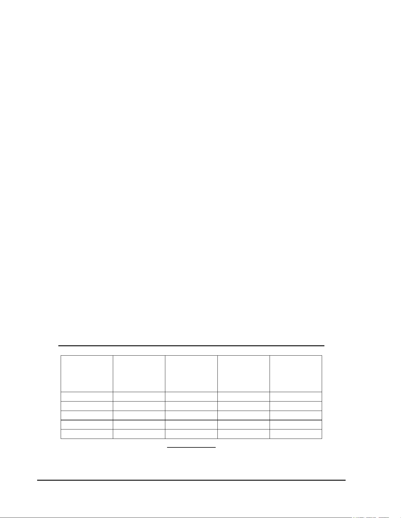
FIGURE: 2.1
MAXIMUM CRITICAL PATH LENGTHS FOR TWO-WIRE PATHS
MAX. LENGTH FOR CRITICAL PATH
LOOP STAR
Nominal
Wire Size
Ohms per 1000’
Or Ohms per
Km
Km Miles Km Miles
2.5 mm2 15.0 Ohms/Km 12.0 7.5 3.0 1.8
*16 AWG 4.09 Ohms/1000’ 9.6 6.0 2.4 1.5
14 AWG 2.58 Ohms/1000’ 15.2 9.6 3.8 2.4
12 AWG 1.62 Ohms/1000’ 24.4 15.2 6.1 3.8
10 AWG 1.02 Ohms/1000’ 39.2 24.4 9.8 6.1
TABLE: 2.1
* These sizes are not recommended due to insufficient physical strength of the wire.
GT27141D Page 5 November 2003
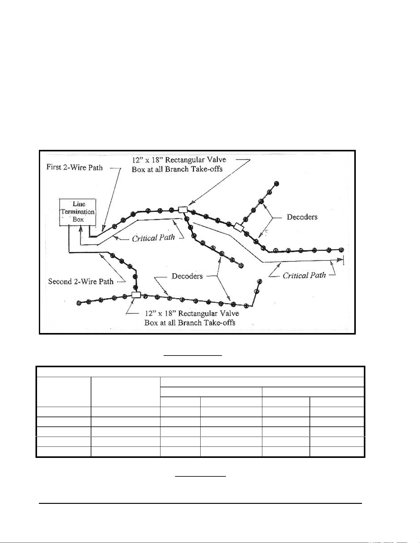
LOOP CONFIGURATION for TWO-WIRE PATH – If the installation requires longer wire
runs, than are possible with the STAR configuration, then a LOOP configuration may be used.
A LOOP configuration requires looping back the two-wire path from the farthest reach back to
the central location and connecting to a terminal in the Line Terminal Box. The main two-wire
path can be looped, and any branch paths from the main two-wire path can also be looped, from
the main line back to the main line. In a LOOP configuration, the Critical Path is the distance
measured by following the two-wire path around the loop out to the farthest decoder and back to
the central. The maximum distance for the Critical Path, for a LOOP configuration is 6.0
miles for 16 AWG cable, 9.6 miles for 14 AWG cable, 15.2 miles for 12 AWG cable and 24.4
miles for 10 AWG cable. For metric cable the maximum distance for the Critical Path is 12.0
Kilometers for 2.5 mm² cable. A diagram of the LOOP configuration layout is presented in
Figure 2.2.
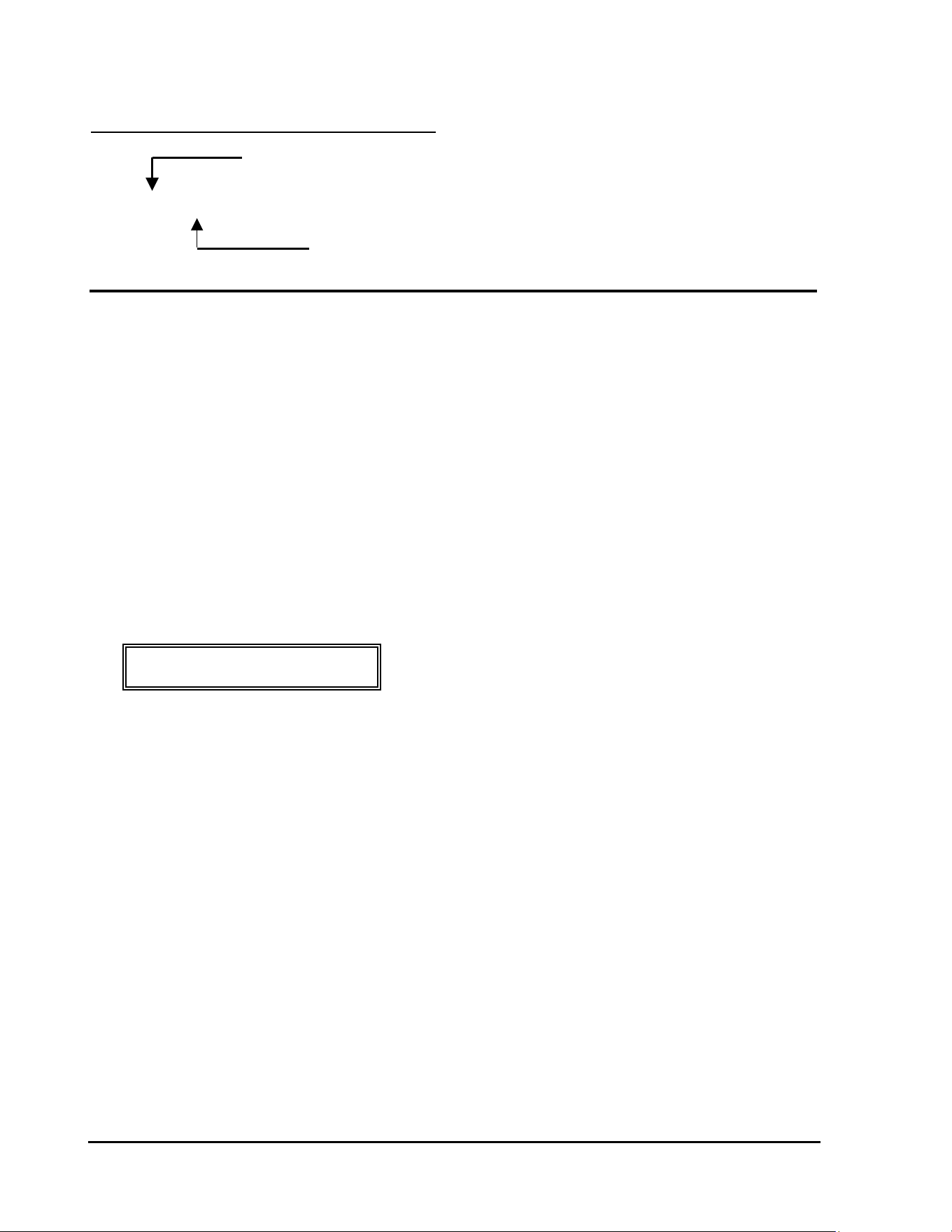
FIGURE: 2.2
GT27141C Page 6 November 2003
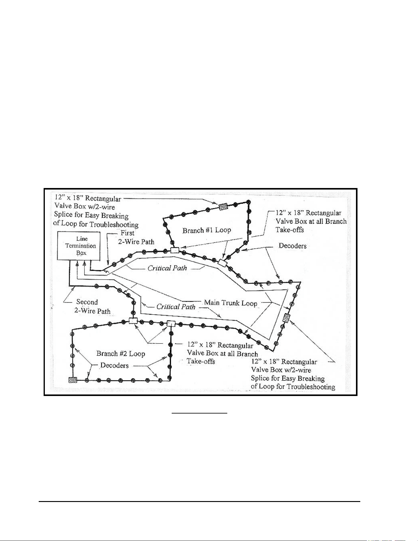
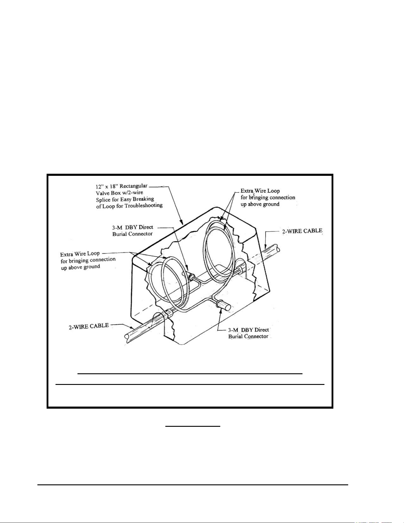
12” x 18” Rectangular Valve Box with 2-Wire Cable Splice
to Facilitate Easy Breaking of the Loop for Troubleshooting Purposes.
SPLICES IN TWO-WIRE PATH – In all splicing locations of the two-wire path, for both the
STAR configuration and the LOOP configuration, all wires shall be clearly marked with
permanent type markings. The wire path should be marked to indicate the trunk wire coming
from the central, the trunk wire continuing out from the splice location and the branch wire off
of the trunk wire. For a LOOP configuration the branch marking should indicate branch LOOP
number. Near the center of each LOOP, in a LOOP configuration layout, make a splice and
place it in a 12” x 18” rectangular valve box. Provide three to four feet of excess wire in the
valve box so that splice may be easily brought above ground for working with it. This is
required for troubleshooting, so that the LOOP may be easily broken, otherwise it will be
impossible to troubleshoot this LOOP to find a short, etc. this method of breaking the wire
LOOP and the marking of all wires, at each splice location, are absolutely necessary to be able
to successfully and easily troubleshoot the system. (Refer to FIGURE; 2.3 below).
FIGURE: 2.3
GT27141D Page 7 November 2003
DECODER CHARACTERISTICS - Decoders are electronic components fully sealed within a
water-tight plastic enclosure that can be buried under-ground away from damage from vandals.
They are an especially good choice for flood plains and in other areas where the risk of satellite
damage is high.
Decoders replace satellites on centrally controlled irrigation systems. The decoders act
as switching stations for digitized commands to sprinkler heads and/or remote control valves.
Underground installation of the decoders and simple, low-cost wiring make decoders an
aesthetically pleasing and economical option for reliable in-field control.
Full in-field control can be realized on the decoder systems by the use of a “plug-in” Field
transmitting portable key pad or the integration of The Freedom system into the decoder system.
Advanced central control technology and simple wiring requirements of decoder systems have
made decoders and ideal choice in the renovation of golf courses. It is now possible to operate
satellites and decoders concurrently on the same central system. Decoder systems also lend
themselves to easy expansion of the irrigation system requiring a minimal amount of wire and
installation time.
DECODER ADDRESSES - The field line decoders, such as, FD-101, FD-102, FD-202,
FD-401, FD-601 and the SD-210 Sensor decoder come furnished with a “FIXED”
FACTORY pre-assigned, four or five-digit address code and are shipped to any particular
installation on a random basis.
The address for newer decoders (decoders produced since 1998) is re-programmable, however,
if this becomes necessary, by using the DPU-210, Decoder Programmer Unit available from
Rain Bird.
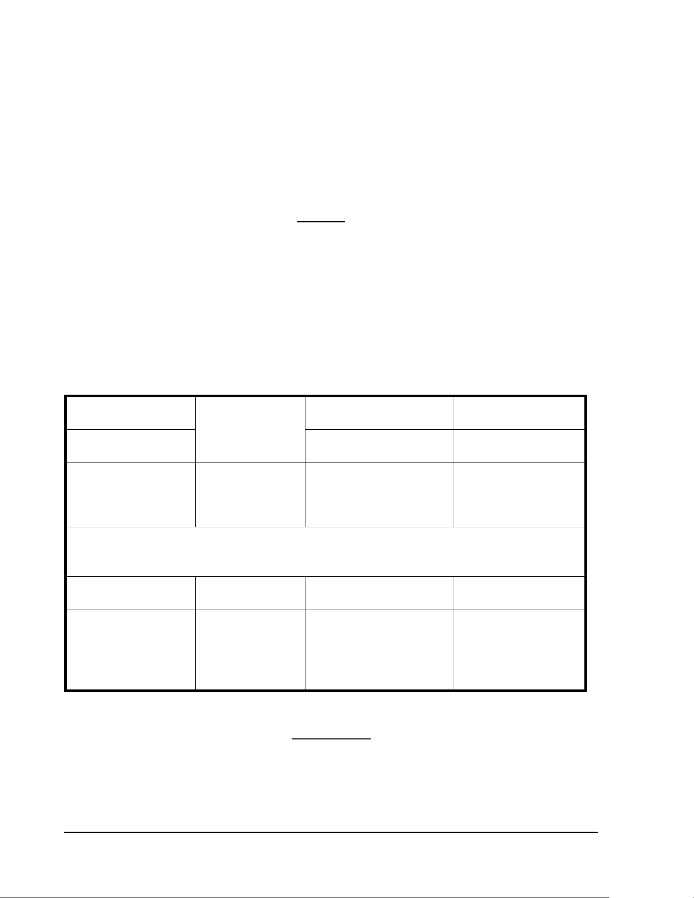
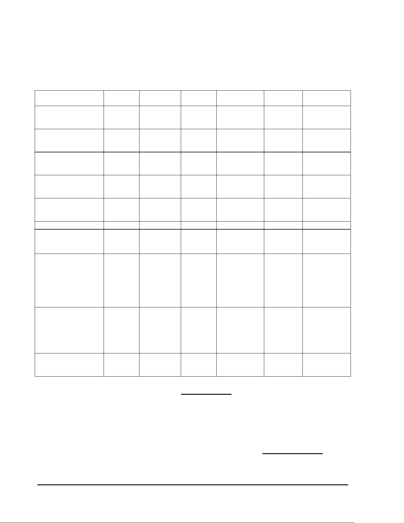
CHARACTERISTIC TABLE for VARIOUS DECODER MODELS
Decoder
Model
Number of
Addresses
Per Decoder
Maximum
Number of
Solenoids
Per Address
Maximum
Addresses
Operating
At Once
Current
Draw (mA)
At Rest
Per Decoder
FD-101 1 1 1 0.5 mA
FD-102 1 2 1 0.5 mA
FD-202 2 2 2 1.0 mA
FD-401* 4 1 4 1.0 mA
FD-601* 6 1 4 1.0 mA
TABLE: 2.2
Has LSP-1 Surge Arrestor built into it.
GT27141C Page 8 November 2003
PULSE DECODER
:
MODEL NUMBER NORMENCLATURE:
Number of Addresses
(1
st
Digit)
1 0 2 = Model Number
Number of Solenoids per Each Output
(3
rd
Digit)
SENSOR DECODER – Model SD-210: Can be used either as a “SENSOR” Decoder or as a
“PULSE” Decoder. Refer to the “Sensor Decoder” Section immediately following this
chart.
PUMP DECODER – Model PD-210: Can be used to control a Pump Station or an Individual
Pump. Refer to the “Pump Decoder” Section following that for the Sensor Decoder below.
SENSOR DECODER – Model SD-210:
The SENSOR DECODER may be used either as a “SENSOR” Decoder or as a “PULSE”
Decoder. The decoder is told by the central system what type of device it is when it makes
contact with the system.
When used as a “PULSE” Decoder it is connected to a Pulse Flow Meter and sends the pulse
back to the Central Control System computer through the MDI Interface Unit for action then to
be taken by the Central System.
FLOW METER - Any type FLOW METER that has a “DRY“ Contact Pulse (“Dry”
contact pulse being a mechanical switch action only – NO voltage or transmitter
frequency being involved) may be used with the “PULSE” Decoder.
APPLICATION - The Pulse Decoder is generally used for;
1) Registration of “System” or “Zone” flow,
2) Search and Elimination of excess flow or adjustment of system under flow, and
3) For instant flow measurement.

GT27141D Page 9 November 2003
SENSOR DECODER
:
When used as a “SENSOR” Decoder it can be connected to any type of sensing device that has a
mechanical “DRY” switch action for the threshold setting, either an “OPEN” switch at the
threshold or a “CLOSED” switch at the threshold, and with NO voltage or frequency being
involved. The SENSOR status changes are transmitted through the MAXI Two-Wire
communication path and the MDI Interface unit to the Central Control System Computer, where
proper system action can take place.
APPLICATION - The most common application of the SENSOR Decoder is
in conjunction with such devices, such as:
1) A Rain Sensing device.
2) A Moisture Sensing device.
3) A Pump Alarm device, etc.
These devices in conjunction with the sensor decoder are used to Start, Stop, and Pause, Re-
adjust or Resume irritation programs.
CONSTRUCTION - The SENSOR decoder is housed and “potted” in a plastic
cylindrical case, similar to the FD-201 line decoder. The unit is completely “POTTED” green
making it waterproof so that it may be direct buried if necessary. The sensor decoder has a four
or five digit address code, just as the other field line decoders.
WIRING - The SENSOR Decoder has two (2) BLUE wires, which are to be connected to
the MAXI Two-Wire communication path. The BLACK wire and the RED wire are to be
connected to the sensor device for the purpose of receiving the sensing device input data. The
two (2) YELLOW and GREEN wires are from the LSP-1 surge arrestor, which is included in
the SD-210 sensor decoder unit. One of these wires should be connected to the sensing device
case and the other wire shall be connected to a ground rod, as specified and required for the
single LSP-1 surge arrestor .
INPUT FUNCTION - The input functions that the SENSOR Decoder is capable of,
are:
a) The Rain Bird Central System polls the Sensor Decoder for data when used as a
pulse decoder it can record 0-200 pulses/minute.
b) When used as 9-sensor decoder, the decoder records an open or closed switch
action.
All functions (also input type) are programmable from the Rain Bird Central System as an
integral part of the sensor installation.

GT27141C Page 10 November 2003
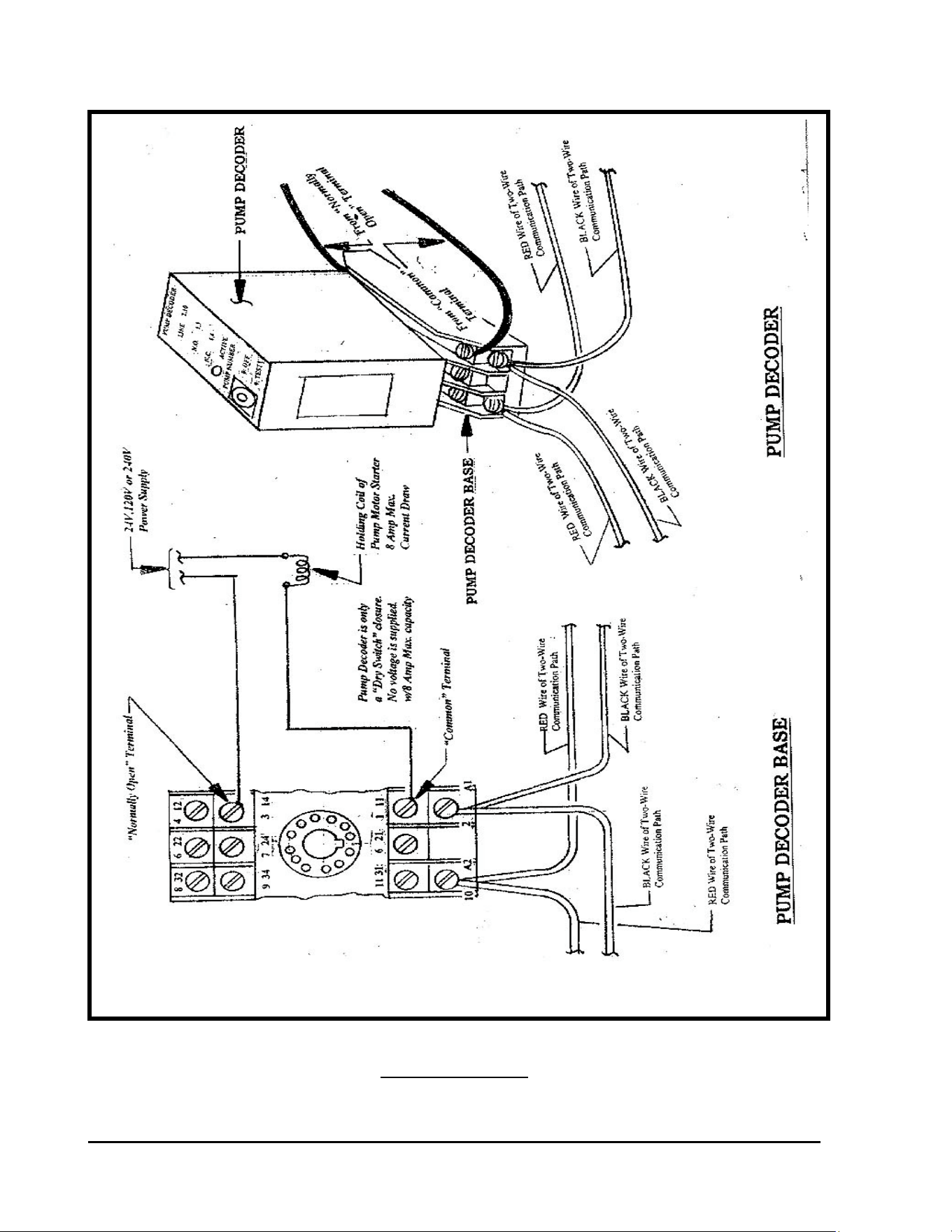
PUMP DECODER - Model PD-210:
The PD-210 PUMP Decoder can be used to control an entire Pump Station, an Individual Pump
and/or a Booster Pump.
The PD-210 Pump Decoder has a selector switch, which allows it to be set to respond to one of
six (6) possible address codes. Thus as many as up to six (6) PD-210 Pump Decoders may be
used on any given system, whether they are controlling Pump Stations, Individual Pumps,
Booster Pumps or any combination of these. The selectable address codes are as follows:
SELECTOR ADDRESS SELECTOR ADDRESS
SETTING CODE SETTING CODE
P1 = 284 P4 = 292
P2 = 286 P5 = 293
P3 = 287 P6 = 295
OUTPUT - The Pump Decoder only furnishes a “Dry Switch Closure” (no voltage output)
and capable of handling up to 240 Volts with a Maximum Current Capacity of 8 AMPs.
CURRENT DRAW - The Pump Decoder, when in the Idle state (not
Activated) has a current draw of less that 0.5mA.
HOLDING COIL - The HOLDING COIL of the Pump Motor Starter can be for any
operating voltage up to 240Volts and with a maximum current draw of 8 Amps. The power
supply for operation of the holding coil must come from some power source, as the Pump
Decoder furnishes NO POWER but only provides a “Dry Switch” closure.
The connection of the PD-210 PUMP Decoder into the Control System shall be as shown in the
diagram below – Refer to FIGURE: 2.4 on the next page.
GT27141D Page 11 November 2003
PUMP DECODER – MODEL PD-210
WIRING DIAGRAM
FIGURE: 2.4
GT27141C Page 12 November 2003
DECODER DESIGN PARAMETERS – In addition to the limitations that govern
the length of the two-wire Critical Path (refer to TABLE 2.1), there are guidelines to follow for
the maximum number of decoder addresses that can be placed on a given two-wire path, and the
number of “ACTIVE” solenoids that can operate simultaneously on a given two-wire path. The
limitations are based on the voltage drop through the Critical Path of the wire run. The
maximum allowable voltage drop is 9 VOLTS. In order to maintain the ability to provide
power to the decoders at the furthest extents of the two-wire path, the resistance of the wire path
musts NOT be greater than 33Ω (OHMS) TOTAL for all wire in the Critical Path. By sizing
the two-wire path and limiting the wire run distance according to TABLE: 2.1 (displayed on
previous pages) the resistance of the two-wire path will not exceed 33Ω. The
actual resistance can be calculated using the resistance’s found in TABLE: 2.3 (below).
RESISTANCE IN OHMS (Ω)
for
VARIOUS SIZES OF MAXI TWO-WIRE PATH CABLE
for ANNEALED COPPER WIRE
Nominal
Wire Size
Type of
Insulation
Resistance in
Ohms at 77° F
Size AWG
Wire
Type (UF)
Thickness
In Inches
Ohms
Per 1000’
16 AWG
14 AWG
12 AWG
10 AWG
Solid
Solid
Solid
Solid
4/64
4/64
4/64
4/64
4.09
2.58
1.62
1.02
METRIC WIRE SIZE DATA
Wire
Size
Wire
Type
Thickness
In Millimeters
Resistance in
Ohms at 25° C
2.0 mm
2
2.5 mm
2
3.0 mm
2
3.5 mm
2
4.0 mm
2
Solid
Solid
Solid
Solid
Solid
0.7 mm
0.7 mm
0.7 mm
0.7 mm
0.7 mm
19/Km
15/Km
13/Km
10/Km
8/Km
TABLE: 2.3
GT27141D Page 13 November 2003
DESIGN CRITERIA – For any given two-wire path the following criteria must be adhered to, as
shown in TABLE: 2.4 below.
CONDITION CIRRUS NIMBUS II NIMBUS STRATUS II STRATUS
& SDC-1
STRATUS LT
Ohms Total for
Critical Path
Calculation
33 Ohms 33 Ohms 33 Ohms 33 Ohms 33 Ohms 33 Ohms
Max Number of
Addresses per
Wire Path
250 250 250 250 250 200
Max Number of
Addresses per
MDI / LDI
500 500 500 500 500 200
Max Number of
Addresses per
SDI
500 500 500 500 500 200
Max Number of
“ACTIVE” Solenoid
per Wire Path
20 20 20 20 20 20
Interface Unit LDI/MDI LDI/MDI LDI/MDI LDI/MDI LDI/MDI SDI
Max Number of
“Active Solenoids
per Interface**
40 40 40 30* 20* 15
Current Draw
At Rest (mA)
FD-101
FD-102
FD-202
FD-401
FD-601
0.5 mA
0.5 mA
1.0 mA
1.0 mA
1.0 mA
0.5 mA
0.5 mA
1.0 mA
1.0 mA
1.0 mA
0.5 mA
0.5 mA
1.0 mA
1.0 mA
1.0 mA
0.5 mA
0.5 mA
1.0 mA
1.0 mA
1.0 mA
0.5 mA
0.5 mA
1.0 mA
1.0 mA
1.0 mA
0.5 mA
0.5 mA
1.0 mA
1.0 mA
1.0 mA
“ACTIVE” Solenoid
Current Draw (mA)
Golf (Green Coil)
“B” (White Wires)
“DV” (Black Wires)
20 mA
25 mA
15 mA
20 mA
25 mA
15 mA
20 mA
25 mA
15 mA
20 mA
25 mA
15 mA
20 mA
25 mA
15 mA
20 mA
25 mA
15 mA
Hybrid System
Max Number of
Interfaces per System
4 3 N/A 2 N/A N/A
TABLE: 2.4
* Software Limitation and Not an MDI Limitation.
** This number of decoders, on a large system with long wire runs, may reduce the
number of ACTIVE decoders that you will be able to operate at one time before the
Interface maximum current draw is exceeded and the Interface “SHUTS-DOWN”
(disconnects from the field wiring).

GT27141C Page 14 November 2003
CALCULATE VOLTAGE DROP – The voltage drop can be calculated using the known
resistance of the wire in the Two-Wire path and the cumulative non-active current draw for all
the decoders along the two-wire path, the cumulative current draw for all the “active” solenoids
on the two-wire path and allowing an additional 30 mA draw for the MDI Lights and SUP-210
surge arrestor are activated.
The calculation can be made using the following formula:
( I x R ) / 2 = V Where: I is current in AMPS (A)
R is resistance in OHMS (Ω)
V is Voltage in VOLTS (V)
GIVEN:
The MDI/LDI (Interface Unit) “Shuts Down” at a current draw of 1100 mA.
Use 1000 mA for design purposes! *
The SDI (Interface Unit) “Shuts Down” at a current draw of 500 mA.
Use 450 mA for design purposes! *
* To allow some safety factor, to handle small “leakage to ground” of current along the Two-
Wire path, which is bound to happen due to poor splices, small nicks in the insulation, etc.
use 1000 mA for design purposes.
Allow 30 mA for the MDI Lights & SUP-210 surge arrestor when active.
Therefore: MDI Lights & SUP-210 surge arrestor = 30 mA
340 (Inactive) Decoders = 340 x 0.5 mA = 170 mA
40 (Active) Solenoids = 40 x 20 mA each= 800 mA
“I” = Total = 1000 mA
BASIC DATA: - The basic data for a Decoder System is as follows:
500 Max.² = Decoder (Addresses) per MDI/LDI Interface Unit.
250 Max. = Decoder (Addresses) per Two-Wire Path.
40 Max. = Active Solenoids per MDI Unit (with 20 mA current draw – each).
20 Max. = Active Solenoids per Two-Wire Path (with 20 mA current draw - each).
9 Volts = Maximum Voltage Drop Allowable per Two-Wire Path.
30 mA (total)= for MDI Lights and SUP-210 when activated.
The LDI uses only 15 mA for the lights as it has a built in SUP-210 that draws no current.
GT27141D Page 15 November 2003
Green Golf Coil @ 20 mA Current Draw
0.5 mA Ea. = for Inactive Decoder (FD-210/FD-102 decoders).
1.0 mA Ea. = for Inactive Decoder (FD-410/FD-202; FD-401 & FD-610/FD-601 decoders).
15 mA Ea. = for Active “DV” Solenoid Coil with Black Wires.
20 mA Ea. = for Active “GOLF” Solenoid Coil (Green Coil).
25 mA Ea. = for Active “B” Solenoid Coil with White Wires.
230 Maximum Inactive Decoders (Addresses) per Two-Wire Path. (250 minus 20 active)
20 Maximum Active Solenoid Coils per Two-Wire Path.
² Although the MDI can handle a maximum of 500 decoders (addresses) total – with any number
over a total of 380 decoders (addresses) the number of active decoders that you will be able to
operate at one time, will be reduced.
EXAMPLE CALCULATION
MDI Lights & SUP-210 when activated = 30 mA
230 Inactive Decoders = 230 x 0.5 mA = 115 mA
20 Active Golf (Green) Solenoids x 20 mA = 400 mA
“I” = Total mA = 545 mA = .545 A
#14 AWG Cable Size for Two-Wire Path @ 2.58 Ω/1000 ft.
Critical Path Length = 2.4 Miles = 2.4 x 5280’ = 12,672 Feet Total
“R” = 12.67(1000’s of feet) x 2.58Ω/1000’ = 32.68 Ω
SUBSTITUTE: (in basic formula)
V = I x R / 2
.545A x 32.68 Ω
V = = 8.90 Volts Drop
2
GT27141C Page 16 November 2003
“B” Coil w/White Wires @ 25 mA Draw
METRIC CALCULATION:
2.5 mm² Cable Size for Two-Wire Path @ 15 Ω/Km
Critical Path Length = 2.2 Km
“R” = 2.2 Km x 15Ω/Km = 33.0 Ω
“I” = .545 A
.545A x 33 Ω
V = = 8.99 Volts Drop
2
EXAMPLE CALCULATION
MDI Lights & SUP-210 when activated = 30 mA
230 Inactive Decoders = 230 x 0.5 mA = 115 mA
20 Active Golf (Green) Solenoids x 25 mA = 500 mA
“I” = Total mA = 645 mA = .645 A
#14 AWG Cable Size for Two-Wire Path @ 2.58 Ω/1000 ft.
Critical Path Length = 2.4 Miles = 2.4 x 5280’ = 12,672 Feet Total
“R” = 12.67(1000’s of feet) x 2.58Ω/1000’ = 32.68 Ω
SUBSTITUTE: (in basic formula)
V = I x R / 2
.645A x 32.68 Ω
V = = 10.54 Volts Drop (Over 9 Volts)
2
GT27141D Page 17 November 2003
Under this condition you would NOT be able to operate 20 of the “B”
type solenoid coils Simultaneously.
16 Solenoids Max. that
can be operated Simul-
taneousl
y
.
The total current draw cannot exceed 545 mA. There is a current draw of 145 mA with
the MDI Lights & SUP-210 and the 230 Inactive Decoders on the Two-Wire Path.
Therefore;
545 mA total minus 145 mA = 400 mA allowable for the Active Solenoids
@ 25 mA per solenoid 400 mA divided by 25 mA =
This can be checked as follows:
#14 AWG Cable Size for Two-Wire Path @ 2.58 Ω/1000 ft.
Critical Path Length = 2.4 Miles = 2.4 x 5280’ = 12,672 Feet Total
“R” = 12.67(1000’s of feet) x 2.58Ω/1000’ = 32.68 Ω
“I” = .545A
SUBSTITUTE: (in basic formula)
V = I x R / 2
.545A x 32.68 Ω
V = = 8.90 Volts Drop (Under 9 Volts)
2
Under these conditions and using the “B” type solenoid – the maximum number of
solenoids that may be operated simultaneously is 16.

GT27141C Page 18 November 2003
SYSTEM EXAMPLE CALCULATIONS
STAR TWO-WIRE PATH CONFIGURATION: -
18 HOLE COURSE
2 – TWO-WIRE PATHS IN STAR CONFIGURATION – One for front nine holes & one
for back nine holes.
36 FD-410/FD-202 decoders – with 2 at each Green operating 2 Solenoids (Golf Coils –
Green) each solenoid at 20 mA current draw.
18 FD-410/FD-202 decoders on each of the Two-Wire paths.
400 FD-210/FD-102 decoders on entire system.
200 FD-210/FD-102 decoders on each Two-Wire path.
10 FD-410/FD-202 decoders desired to operate at one time on a Two-Wire path.
(2 solenoids on each decoder equaling 20 solenoids total, which is the maximum that
can operate simultaneously on a Two-Wire path.)
Critical Two-Wire path length = 2.2 Miles
Wire size is #14 AWG cable @ 2.58 Ω/1000’
CALCULATION:
“R” = 2.2 Mi. x 5280’/Mi. = 11,616 feet total length
= 2.58Ω/1000’ x 11.626 (1000’s of feet) = 30.0 Ω
“I” = MDI Lights & SUP-210 when activated = 30 mA
200 (Inactive FD-210/FD-102 @ 0.5 mA each) = 200 x 0.5 mA = 100 mA
8 (Inactive FD-410/FD-202 @ 1.0 mA each) = 8 x 1.0 mA = 8 mA
10 (Active FD-410/FD-202 w/2 coils each @ 20 mA per coil
or 40 mA total for each decoder) = 10 x 40 mA = 400 mA
TOTAL = 538 mA
“I” = .538 A
I x R .538 A x 30.0 Ω
V = = = 8.07 Volts Drop
2 2

GT27141D Page 19 November 2003
GT27141C Page 20 November 2003
L
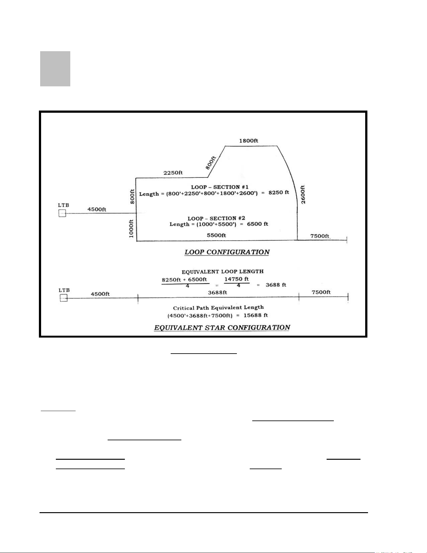
OOP TWO-WIRE PATH CONFIGURATION: - In order to
calculate the voltage loss for a “LOOP” type Two-Wire path you must first convert
the LOOP system into an equivalent “STAR” type system for determining the Critical
Path Length for the Two-Wire path. Refer to FIGURE: 3.4 shown below.
FIGURE: 2.5
NOTE ! In referring to FIGURE: 2.5 above, you will note that the “Equivalent
Loop Length” in the STAR configuration, is ¼ (one fourth) the total
Length of the LOOP in the LOOP configuration.
The length of Section #1 of the LOOP is = 800’ + 2250’ + 800’ + 1800’ + 2600’ = 8250 feet.
The length of Section #2 of the LOOP is = 1000’ + 5500’ = 6500 feet.
CONVERTING A “LOOP” TWO-WIRE PATH TO AN
EQUIVALENT “STAR” TWO-WIRE PATH
GT27141D Page 21 November 2003
Thus the “Equivalent Loop Length” of the LOOP is:
8250’ + 6500’ 14,750 ft
= = 3688 feet
4 4
The Critical Path Equivalent Length = 4500’ + 3688’ + 7500’ = 15,688 feet
Wire size is #14 AWG cable @ 2.58 Ω/1000’
CALCULATION:
“R” = 15.7(1000’s of feet) x 2.58Ω/1000’ = 40.5 Ω
“I” = MDI Lights & SUP-210 when activated = 30 mA
200 (Inactive FD-210/FD-102 @ 0.5 mA each) = 200 x 0.5 mA = 100 mA
8 (Inactive FD-410/FD-202 @ 1.0 mA each) = 8 x 1.0 mA = 8 mA
10 (Active FD-410/FD-202 w/2 coils each @ 20 mA per coil
or 40 mA total for each decoder) = 10 x 40 mA = 400 mA
TOTAL = 538 mA
“I” = .538 A
I x R .538 A x 40.5 Ω
V = = = 10.9 Volts Drop∗
2 2
∗The voltage drop is in excess of 9 Volts, therefore the wire
size needs to be increased or less solenoids operated in order to
reduce the current draw and result in a lower voltage drop.
To calculate the number of solenoids that could be operated simultaneously – keeping the same
wire size . . .
9 Volts = Maximum Voltage Drop Allowable
“R” remains the same at 40.5Ω
GT27141C Page 22 November 2003
N
OTE ! As long as the voltage drop is equal to or less than 9 volts, the two-
wire path will be able to power all the decoders.
Solve for the maximum current allowable under these conditions to stay at 9 Volts or less voltage
drop.
V x 2 9V x 2 18
I = = = = .494 A
R 40.5Ω 40.5Ω
MDI Lights & SUP-210 when activated = 30 mA
200 (Inactive FD-210/FD-102 @ 0.5 mA each) = 200 x 0.5 mA = 100 mA
8 (Inactive FD-410/FD-202 @ 1.0 mA each) = 8 x 1.0 mA = 8 mA
Total = 138 mA
494 mA – 138 mA = 356 mA available
At 20 mA draw per solenoid - 356 mA divided by 20 mA = 16 solenoids
maximum
can be operated simultaneously on this LOOP Two-Wire Path. This
would limit the system to 8 FD-410/FD-202 decoders operating simultaneously
GT27141D Page 23 November 2003
SECONDARY PATH WIRE RUN – In addition to the parameters for sizing the Primary Two-
Wire Path Wire Run, there are considerations for the Secondary Path Wire Run. The
Secondary Path Wire Run is the wire path connecting the
decoder output to the electric solenoid on the valve-in-head sprinklers or the remote control
valves. The maximum total wire path length, from the decoder to the farthest solenoid, for
different wire sizes is given in TABLE: 2.5 below. For a single solenoid being connected to the
decoder output, the length, from the decoder to the solenoid, may be taken directly from the
table. When two (2) solenoids are being connected to the decoder output, the total length is the
distance from the decoder to the first solenoid plus the distance again from the decoder to the
second solenoid. (Refer to FIGURE: 2.6 below).
MAXIMUM WIRE RUN LENGTHS
for
SECONDARY PATH WIRE RUNS
Wire Size Secondary Wire Run Lengths
METERS FEET
1.5 mm² 100 328
2.0 mm² 133 436
2.5 mm² 166 545
16 AWG 88 289
14 AWG 139 456
12 AWG 220 720
TABLE: 2.5
For a single solenoid connected to the decoder output, the maximum length may be taken
directly from the TABLE: 2.5 above.
When two (2) solenoids are connected to the decoder output, the total maximum length shall be
as calculated in the example in FIGURE: 2.6 below.
GT27141C Page 24 November 2003
Electric Solenoid on Valve-in-head
Sprinkler or Remote Control Valve
White
DECODER White
115 feet
Blue 35 meters
Blue
213 feet
Connect to
2-wire path 65 meters
115 ft. + 213 ft. = 328 ft. - Use size 14 AWG wire
35 M + 65 M = 100 M - Use size 1.5 mm² wire
DECODER
SECONDARY WIRE RUN CALCULATION
for
TWO SOLENOIDS CONNECTED to the DECODER
OUTPUT
FIGURE: 2.6
The maximum total length of the secondary wire path, when two (2) solenoids are connected to
the decoder output, is defined as the sum of the wire path distance from the decoder to the first
solenoid plus the wire path distance again from the decoder out to the second solenoid. This
means that the section of the wire path that is powering both of the solenoids (the 115 feet/35
meter length in Figure: 2.6) is counted twice.

GT27141D Page 25 November 2003
FIELD SPECIFICATIONS – Each two-wire path must NOT exceed the maximum wire run
for its Critical Path. (Refer to FIGURES – 2.1 & 2.2 for Critical Path measurement and refer
to TABLE 2 .1 for maximum Critical Path lengths.) A maximum of 250 single address
decoders (FD-102) may be connected on a given two-wire path. A maximum of 125 Multi-
address decoders (FD-202, FD-401, or FD-601) may be connected on each two-wire path. Or
any combination of Single Address decoders and Multi-address decoders may be combined on a
given two-wire path as long as the TOTAL Non-Active current draw does not exceed 115 mA.
A maximum of 500- single address decoders (FD-102) may be connected to any individual MDI
Interface Unit. A maximum of 250 Multi-address decoders (FD-202, FD-401, or FD-601) may
be connected on any given MDI Interface Unit. Or any combination of Single Address decoders
and Multi-address decoders may be combined on a given MDI Interface Unit as long as the
TOTAL Non-Active current draw does not exceed 230 mA. (Refer to TABLE 2.4 for
complete information). The maximum number of “ACTIVE” solenoids on any given two-wire
path is 20. The FD-102 decoders powering 2 solenoids each is considered as TWO “ACTIVE”
SOLENOIDS even though using only ONE address. The maximum number of “ACTIVE”
solenoids on any given MDI Interface Unit varies by SYSTEM TYPE. (Refer to TABLE 2.4 for
maximum number of solenoids for each type system.)
It should be noted that the requirement is for a maximum number of SINGLE ADDRESS
DECODERS and/or MULTI ADDRESS DECODERS and not JUST the number of Decoders.
An FD-101 and FD-102 is ONE decoder address and thus a Single Address Decoder.. Likewise,
the FD-202 is TWO decoder addresses, the FD-401 is FOUR decoder addresses and the FD-601
is SIX decoder addresses and are therefore Multi Address Decoders.
CENTRAL SPECIFICATIONS – The Rain Bird Decoder System may contain multiple two-
wire paths – in fact it is STRONGLY RECOMMENDED that multiple two-wire paths be
designed into the system rather than just one large two-wire path. The MINIMUM number of
Two-Wire paths is dictated by the number of Single Address Decoders and Multi Address
Decoders that you have on your system and the type of wire system; i.e. STAR or LOOP
type
two-wire path. (Refer to TABLE 2.4 for further information.) The decoders must be
divided into separate two-wire paths according to the specification previously mentioned.
All of the decoders, on a decoder system, must have a unique four or five digit address code.
These address codes are used by the Central Control system to control each decoder individually.
For purposes of programming and daily operation of the system, each decoder is also given a
specific “programming” name by the operator or programmer, which usually identifies the type
area it is servicing and the location on the course. This is for ease of programming and daily
operation, rather than try to remember the specific decoder’s four or five digit address code.
The computer can then in turn send the specific four or five digit address code to the field for
actual operation of the decoder.

GT27141C Page 26 November 2003
Chapter
3
Installation of Decoders and
Wiring for the System
The Successful Installation of a Decoder System Requires Careful
Adherence to Proper Installation Procedure, Especially in Making
the wire splices.
It is of the utmost importance that a Decoder system be installed properly since the entire system,
once installed, will be underground and therefore not easy to access should any alterations or
repairs be required. A system installed correctly will function trouble-free for many years to
come. A system that is installed without heeding the installation guidelines will most likely
require undue maintenance and troubleshooting, possible “down-time” and could result in
expensive service and repair bills. In this chapter and succeeding chapters, important
requirements for the correct installation of a Decoder system will be presented. Proper wiring
methods, surge protection, and grounding requirements will be discussed. The most
important step in the installation of a decoder based irrigation system is the field and
decoder wiring. It is definitely to the installer’s advantage to take extra care during the
wiring phase of the project.
It is recommended that all sections of these guidelines be read thoroughly before focusing on the
sections that apply directly to the design being installed.
Terminology: “Primary Path” - Wiring from Line Termination Box to field decoders out to
the farthermost point from LTB.
Types of Primary Paths – “Star” and “Looped” configurations. (Looped is NOT
recommended due to difficulty in troubleshooting the system.)
“Critical Path” – Longest distance, measured along the wire path, from the LTB out to the
farthermost decoder away from the LTB.

GT27141D Page 27 November 2003
“Branches” or “Branch Loops” - Wires that “spur off” the Critical Path, to pick up
decoders.
“Secondary Path” - The wire that extends from the decoder output to the solenoid(s) of the
remote control valve or the valve-in-head sprinkler.
A Decoder system is relatively easy to install and set-up. Special attention must be paid to three
areas in order for the system to function up to its maximum capabilities, these areas are:
1. Installation of the two-wire communication path and most importantly the
wire connections (splices).
2. Proper installation of surge protection equipment and devices.
3. Proper installation and maintenance of the grounding systems.
If these areas are properly installed, the system can be ensured of proper operation as well as
limiting unnecessary damage to equipment due to voltage surges occurring on the system.
Failure to provide proper protection and proper installation, in these areas, can result in costly
service and repair bills for the golf course, as well as down time for the system, due to surge
damage.
This chapter is presented in an effort to stress the need for proper installation and proper surge
protection for the decoder system. The information is presented using two formats. One form
is a set of detailed installation drawings that summarizes exactly what surge protection, wiring,
and grounding is required and how it is to be installed.
The second is a written description of the installation procedures and surge devices required, as
well as, the necessary grounding of these devices and/or the equipment.
GETTING STARTED WITH THE INSTALLATION
FIELD WIRING - The first step is to become familiar with the wiring layout for the two-
wire paths. The wiring for the two-wire paths is recommended to generally follow the piping
of the system, as much as practical. It is also strongly
recommended that the two-wire path wiring be laid out in a “STAR” or “branched”
configuration, terminating in a number of dead ends. (Refer to FIGURE: 2.1) This is
primarily for the ease of potential troubleshooting in the future. It is important that a “LOOP”
configuration does NOT occur any where in the two-wire path unless the system has been
specifically designed as a “LOOP” type system. (Refer to FIGURE: 2.2)
GT27141C Page 28 November 2003
CONTINGENCY WIRING – It may be advisable to consider installing some “contingency”
MAXI Two-Wire cable, which can allow a given area of the system to be electrically controlled
from a different direction if a fault occurs on the primary communication path.
All two-wire cable designated as “CONTINGENCY” cable shall be installed with all ends
disconnected. Wire ends shall be placed in 3-M type DBY or DBR electrical connectors and
housed in a 10” Diameter round valve box, with cover and marked “ELECTRICAL”.
COLOR CODED CABLE – Each two-wire path shall have a differently colored outer jacket on
the MAXI cable. All branches from the main trunk line (Critical Path) of the two-wire path
shall also be of the SAME color outer jacket as that of the main trunk line of the two-wire path.
It is extremely important NOT to mix cable colors on any given two-wire path, just as it is
important that EACH two-wire path have its own different colored outer jacket on the cable and
no two-wire paths with the same color cable. Color coding of the two-wire path cable can be an
invaluable troubleshooting tool in the future.
Installation of Wire
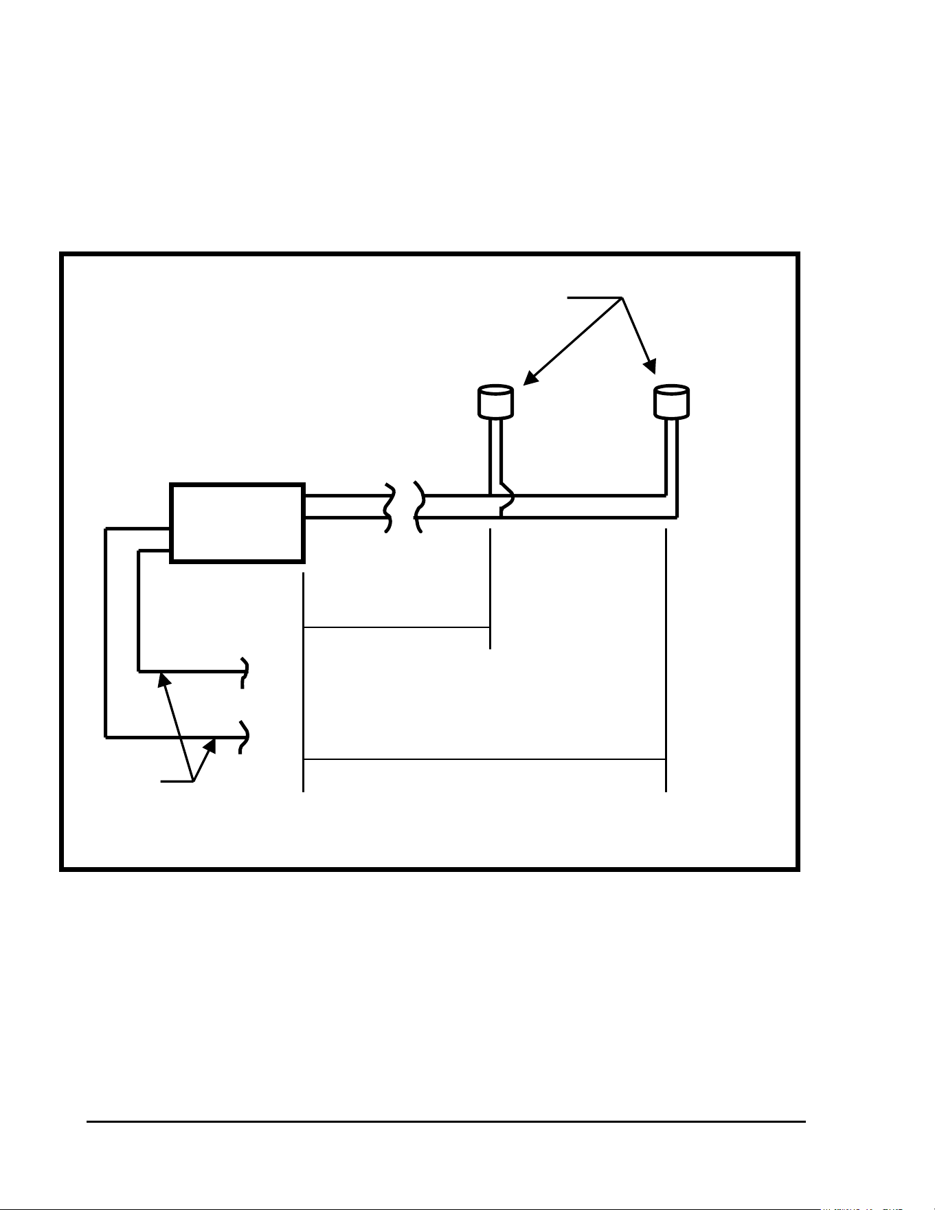
WIRE INSTALLATION ON A NEW CONSTRUCTION – When wire is being installed at
the same time as new piping, it shall be laid on top of the 6” layer of clean back fill that covers
the pipe. In rocky conditions the trench shall have a 6” layer of clean sand on the bottom of the
trench before backfilling is started. If rocky back-fill is being used (which is NOT
recommended), the wire shall have a 6” layer of sand on top of it, before backfilling is started.
The wire shall have a
minimum of 18” cover on it
after backfilling is
completed.
It is necessary to maintain
consistency as to which side
of the trench the wire is laid.
By so doing you reduce the
risk of damaging the wire
should it be necessary to dig
in the area to repair a
pipeline leak or break. For
example; looking down a
golf hole from the tee to the
green, always lay the wire on the left side of the trench.
FIGURE: 3.1
Refer to FIGURE: 3.1
at the right.
GT27141D Page 29 November 2003
Where wire passes under roadways, cart paths, walls, or any other paved areas or where it may
be attached to the under side of bridges, etc., it shall be installed in a minimum of a 2” size PVC
Schedule 80 pipe conduit or a conduit that meets local codes.
WIRE INSTALLATION ON AN EXISTING SYSTEM – Where the two-wire cable is being
installed on an existing system, the cable may be laid using a vibratory plow with a wire sleeve
of sufficient size to prevent scoring of the outer jacket or putting friction on the outer jacket. It
must never be “pulled” in. When the wire is laid with a vibratory plow – extra care must be
taken to be sure the wire does NOT catch in the sleeve and cause the copper conductors in the
cable to be stretched, which produces a weak spot and very subject to future fracture of the
conductor. If the copper conductor is stretched too much an actual break may occur in the
conductor within the insulation jacket and remain undetected at the time of installation. This,
of course, can cause considerable time and labor to later “pin-point” the location of the
conductor fracture and correct it.
Making of Wire Splices
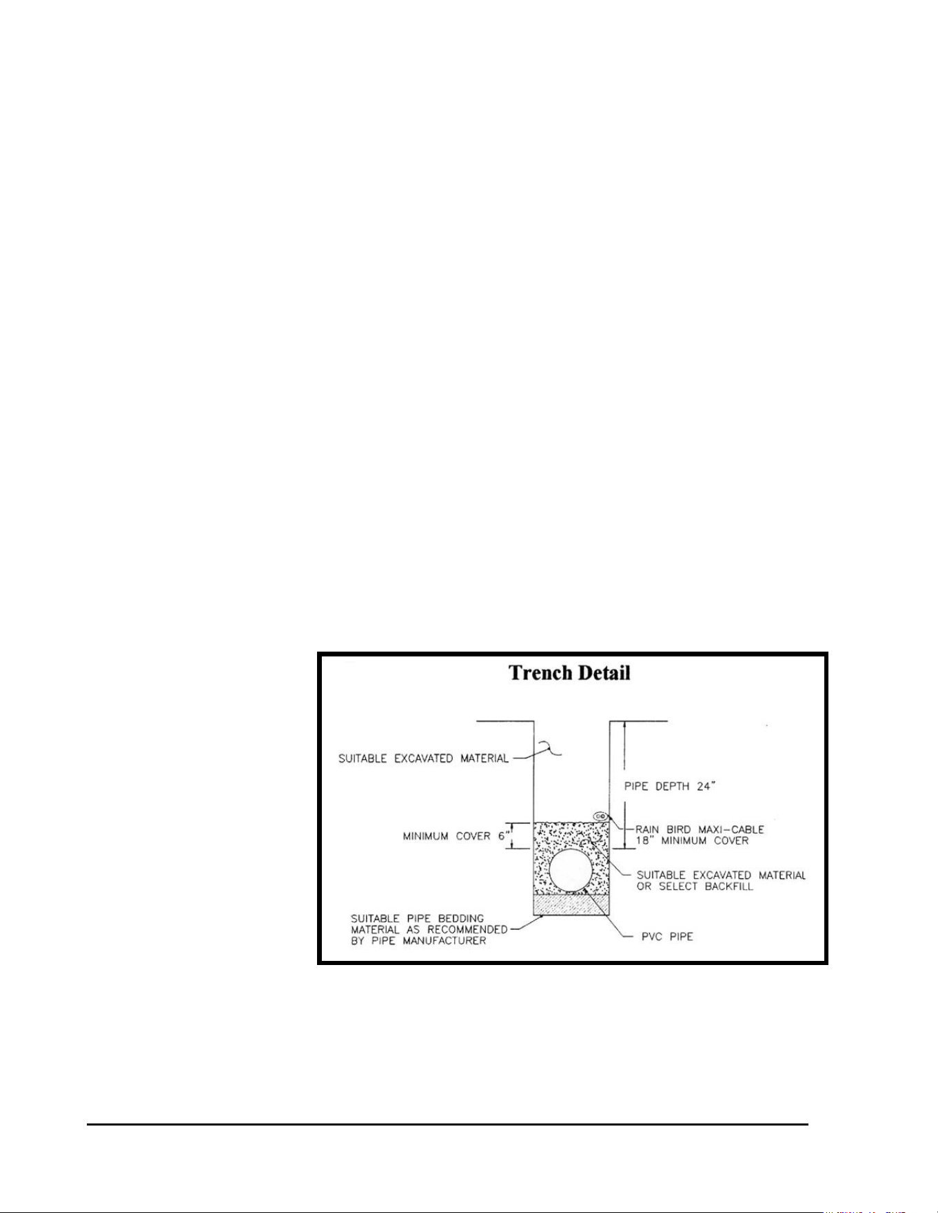
WIRE SPLICES – Wherever splices are made in the two-wire path or decoder wiring, they
shall be placed in a valve box. The only exception to this is for decoders at Valve-in-Head
sprinklers, where the decoders and wire splices may be direct buried, or unless other methods of
installation are desired, such as; placing them in a small round valve box, in a pipe sleeve with
cover, etc. This will be discussed further later in these guidelines. This means that ALL main
trunk line splices and ALL branch take-off connections MUST be placed in a valve box. Valve
box shall be a minimum of 10” in diameter with cover or a 12” x 18” rectangular type valve box
with cover. Sufficient slack shall be left at each connection and splice to allow wire and
connectors to be lifted a minimum of one foot (1’-0”) above the finished grade level for ease of
testing and troubleshooting of wire cable. Refer to FIGURE: 3.2 below.
Typical Wire
Splice in a
Rectangular
Valve Box
FIGURE: 3.2
GT27141C Page 30 November 2003
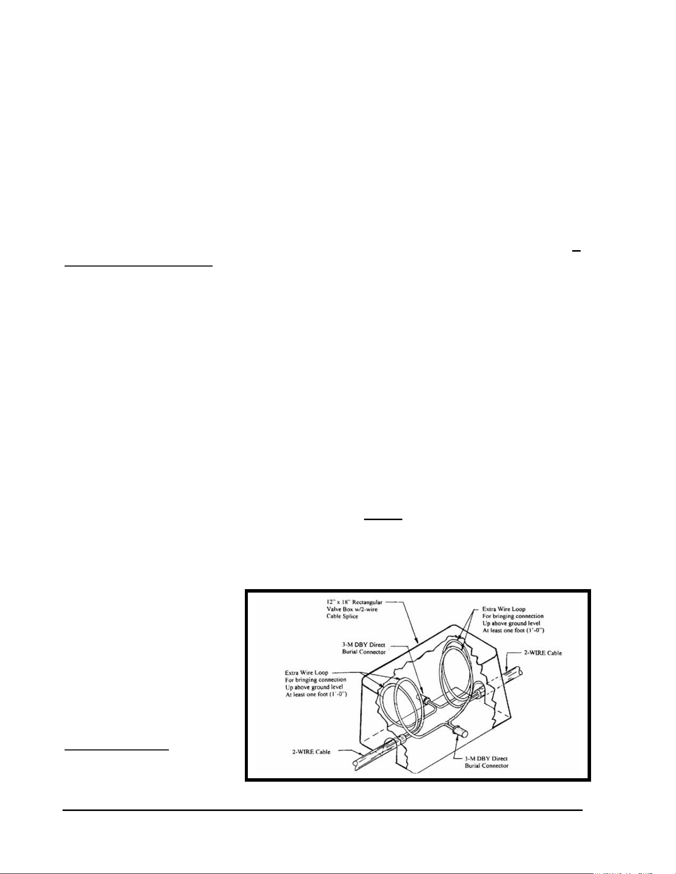
Marking of Wire Splices
WIRE SPLICE MARKING – All wires in a valve box shall be permanently identified as to
their routing direction or the holes they feed using a permanent
marking pen and marking on the cable outer insulation jacket or using some other suitable
permanent tag (metal, plastic, etc.) to identify the wire. Refer to FIGURE: 3.3 below.
Be absolutely certain this step is not overlooked, as it can save time and frustration,
should wire troubleshooting be necessary in the future.
FIGURE: 3.3
Stripping the Outer Jacket
STRIPPING THE OUTER JACKET OF THE MAXI TWO-WIRE CABLE - As noted
earlier, extreme care is necessary during the wiring phase of the project. The following is a
detailed description of the best method to strip the outer jacket of the two-wire cable that
minimizes the chances of cutting through the inner insulation and into the copper conductors
themselves.
Strip approximately 6” of the outer jacket of the cable for all the splices that are to be made.. It
can be difficult to attempt to remove all 6” of the outer insulation in one piece, so remove it in
two 3” sections.
GT27141D Page 31 November 2003
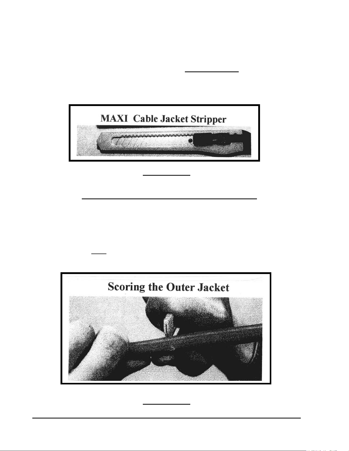
The acceptable knife that allowed for this procedure is the small snap-off blade variety. Refer to
FIGURE: 3.4 below. It is recommended that you grind off the point of the knife blade to
minimize the chances of piercing the inner insulation. The King Safety stripper may also be
used but care must be taken to cut away from the conductors when removing the remaining outer
jacket so as not to damage the inner conductor insulation.
FIGURE: 3.4
The blade of the knife should be set and locked at its minimum extension to prevent a cut in the
inner insulation. This is the most crucial aspect of the entire wiring procedure. DO NOT use
hook knives, pocket knives, utility knives, or ROMEX strippers since you have no way to limit
the depth of your cut and therefore all have the possibility of cutting through the inner insulation
if you attempt to use them.
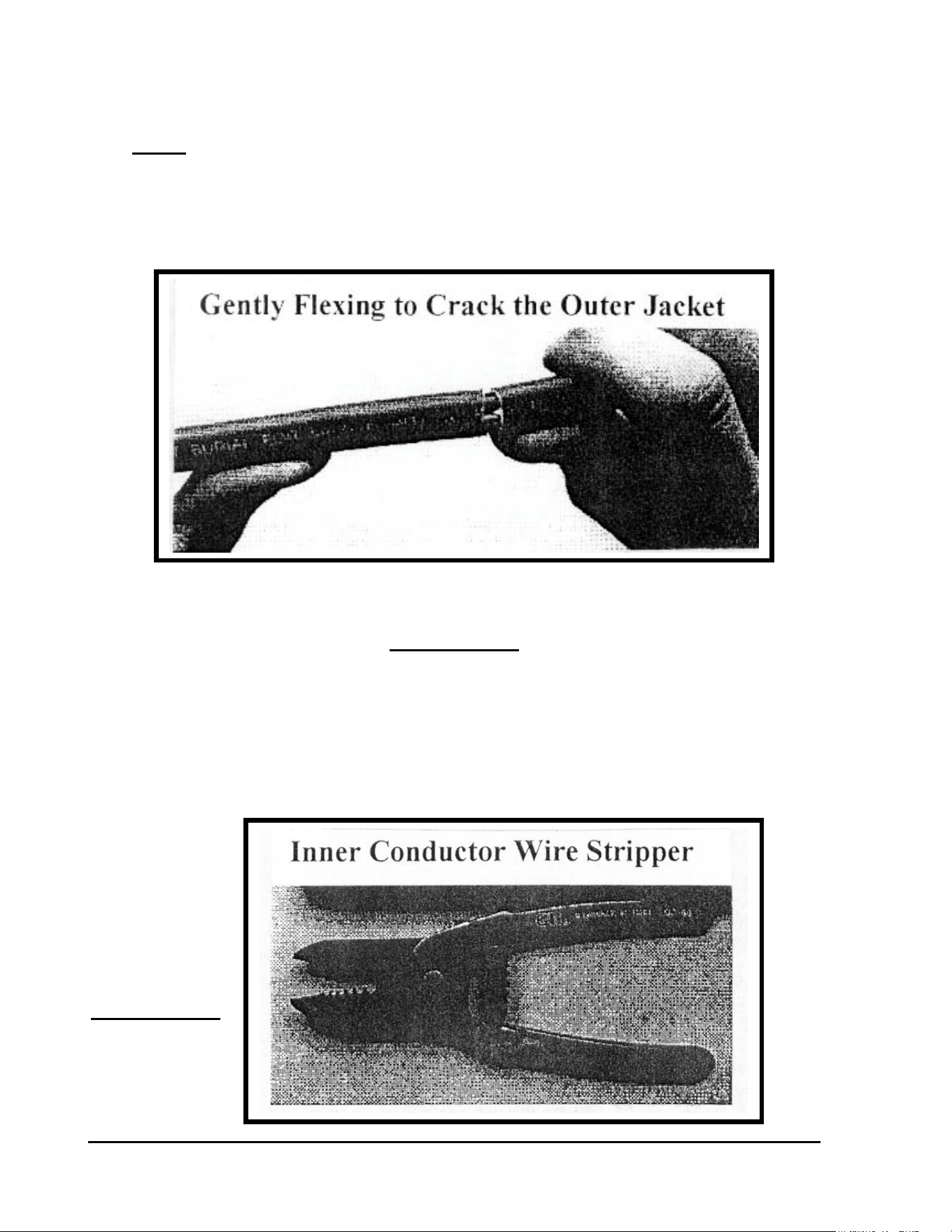
Hold the MAXI two-wire cable in one hand and while holding the blade against the outer jacket
with the other hand, score the outside of the jacket. Refer to FIGURE: 3.5 below.
FIGURE: 3.5
GT27141C Page 32 November 2003
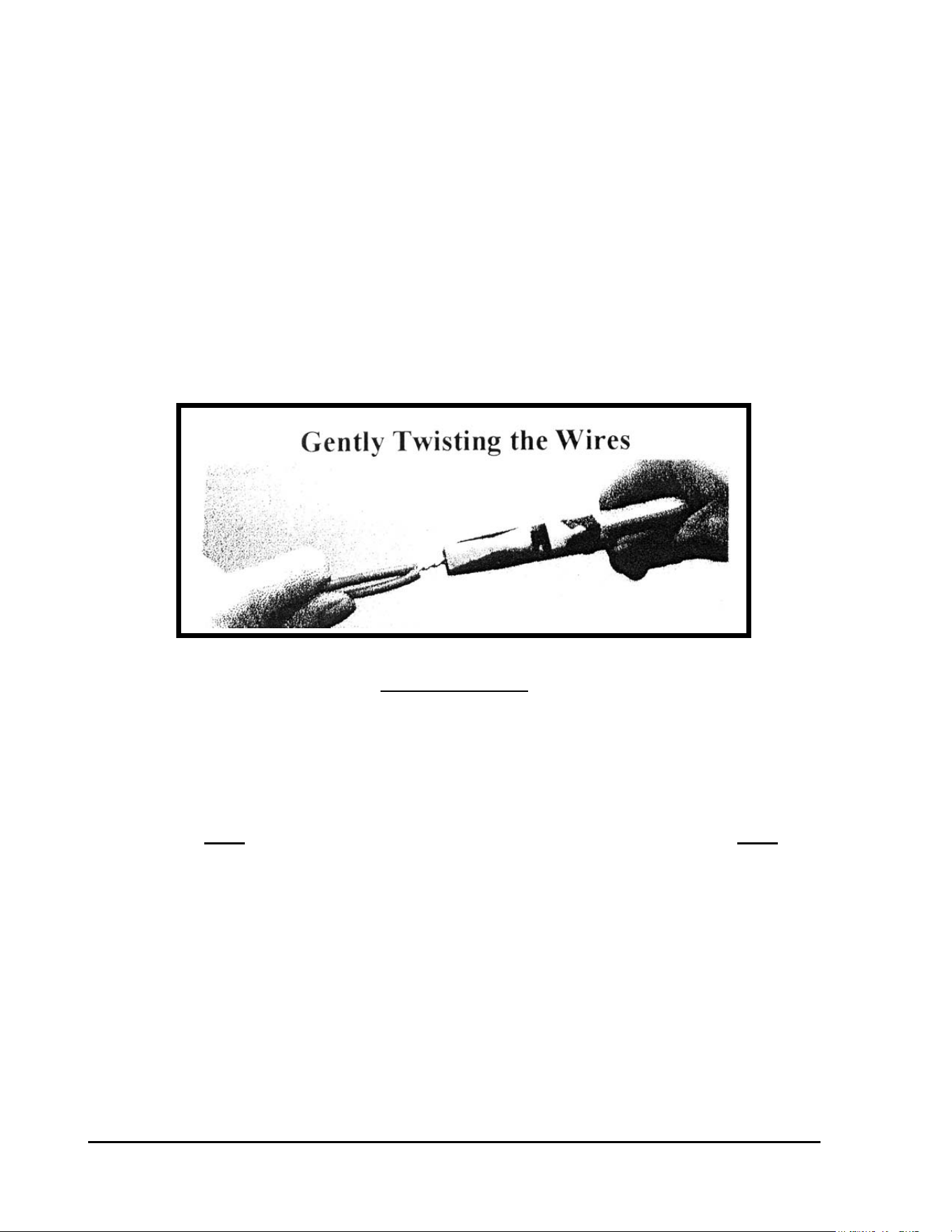
Now Gently flex the cable to crack the outer jacket. Refer to FIGURE: 3.6 below. DO NOT
bend it back and forth more than is absolutely necessary since it is possible to break the inner
conductor within the inner insulation and not be aware that it happened. Once the outer jacket is
cracked, simply pull the outer insulation jacket off, leaving the two inner PVC insulated
conductors, one RED and the one BLACK, exposed.
FIGURE: 3.6
After about 6” of the RED and BLACK insulated conductors are exposed, use a wire strippers of
proper gauge to remove approximately 5/8” of the PVC inner insulation from these conductors.
A wire stripper similar to that pictured in FIGURE: 3.7 below has been found to work best,
since they can also strip the insulation from other conductors encountered during the installation.
FIGURE: 3.7
GT27141D Page 33 November 2003
Making the Wire Splice
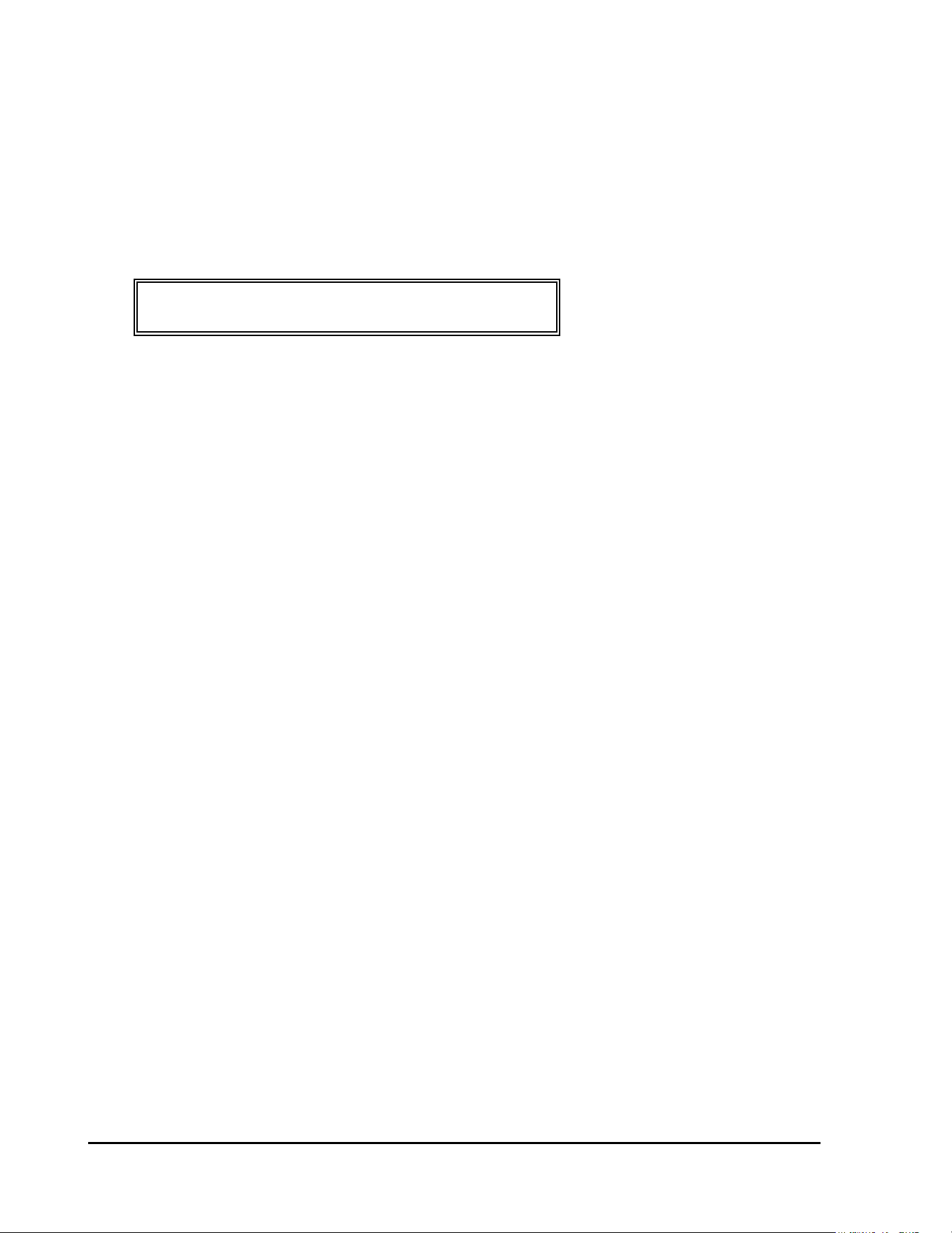
MAKING WIRE SPLICE – When making an inline wire splice use a linesman’s pliers to
gently twist one of the red insulated conductors to the other red insulated conductor and one of
the black insulated conductors to the other black insulated conductor. Place no more than three
or four twists in the wire. Twisting the wires in excess can fracture the conductors. Refer to
FIGURE: 3.8 below.
FIGURE: 3.8
Other splicing techniques will be covered later in this manual for guidelines in regard to decoder
wiring. The following points hold true in every splice that will be made, however, and are
VERY important.
• Do NOT lay the two wires together to be held by the wire nut and do NOT over
tighten the twists as it is possible to stretch the wire and weaken it, which can then
break when wire-nutted and the break may not be apparent to you.
• When the wires are twisted together, firmly hand tighten the appropriate size wire
nut onto the twisted wire and push it into the DBY or DBR connector as far as
possible and secure the cap.
• If making a three-way splice, mark the wires permanently with the hole numbers or
areas of the golf course the wire comes from and where each is going.
• This and all other splices should be placed in a valve box with the mandatory one foot
(1’-0”) above grade minimum amount of slack.
GT27141C Page 34 November 2003
GENERAL INSTRUCTIONS:
DECODER WIRING PROCEDURES:
The following instructions shall apply to ALL the different wiring configurations presented here
in this section of the manual.
WIRING OF DECODER INPUT & OUTPUT WIRES – Each remote control valve will be
wired to a decoder and the decoder in turn wired into the Two-Wire communication path. The
two (2) blue wires of the decoder connect into the Two-Wire communication path, one to the
RED insulated wire of the Two-Wire cable and the other to the BLACK insulated wire of the
cable. It does not matter which of the blue wires, of the decoder, connect to the red and which
to the black wire of the two-wire cable. The two output decoder wires are white and each
connect to one of the two wires from the solenoid coil. Again it does not matter which of the
wires from the decoder connect to which wires of the solenoid coil. The procedures for proper
splicing of an inline splice apply. It may be necessary to strip a small additional amount of the
insulation from the blue and white wires of the decoder as well as from the wires of the solenoid
coil to provide enough bare copper conductor to work with in making the splice.
After you have made the “twist” connection of the RED to RED insulated wires and the
BLACK to BLACK insulated wires of the two ends of the Two-Wire communication cable,
you are ready to connect the blue wires from the decoder. Lay the bare copper conductor, from
one of the blue decoder wires, into the twisted wire “groove” between the two copper
conductors from the RED insulated wire splice and follow the twist using either your fingers or
linesman’s pliers. Repeat for the other blue wire from the decoder, laying the conductor into
the twisted wire “groove” between the two copper conductors from the BLACK insulated wire
splice and follow the twist using either your fingers or linesman’s pliers. Place a wire nut on
each of these splices and then insert each splice into a 3-M DBR connector, making sure you
insert it into the connector as far a possible, and then snap the cap securely in place. Refer to
FIGURE: 3.9 below.
GT27141D Page 35 November 2003
FIGURE: 3.9
CONNECTING THE DECODER OUTPUT –The decoder white output wires are to be
connected to the wires on the solenoid coil of the Valve-in-Head sprinklers or the remote control
valve. It may be necessary to strip a small amount of additional insulation off the solenoid
wires, as well as, from the decoder white output wires to provide enough bare copper conductor
to work with in making the splices. Take one of the white decoder output wires and hold it
parallel to one of the solenoid coil wires and using your fingers or a linesman’s pliers, twist the
two wires together. Use a CLOCKWISE direction in making the twist so that in applying the
wire nut it will not cause the wires to “un-twist”. Repeat this procedure for the other decoder
white output wire and the remaining solenoid coil wire. Place a wire nut on each of these
splices and then insert each splice into a 3-M DBY connector, making sure you insert it into the
connector as far as possible, and then snap the cap securely in place. Refer to FIGURE: 3.10
below.
FIGURE: 3.10

GT27141C Page 36 November 2003
SPLICING TECHNIQUES – The following points hold true in every splice that you will
be making and all are very important.
• Do NOT lay the two wires together and depend on a twist being made by the wire nut
• Do NOT over tighten the twists as it is possible to stretch the wire and weaken it,
which can then break when the wire nut is applied and the break may not be apparent
to you.
• When the wires are twisted together, firmly hand tighten the appropriate size wire
nut onto the twisted wire and push it into the DBY or DBR connector as far as
possible and secure the cap.
• If making a three-way splice, mark the wires permanently with the hole numbers or
areas of the golf course the wire comes from and where each is going.
RECORDING OF DECODER ADDRESS CODE – At this point, record the four or five
digit decoder address code, on either a “Start-Up Work Sheet” and/or on a drawing of the
irrigation system layout for the course, making sure you identify the proper location in the field
for this decoder. This data will need to be on the “Start-Up Work Sheet” along with all the other
necessary information to do the initial data entry into the computer. The decoders can be
installed in any random address code order and do not need to be installed sequentially. The
important thing is to accurately record the address code at the proper decoder.
This section covers the different wiring configurations commonly
encountered in a decoder system. Any given installation may
incorporate several of these concepts.
GT27141D Page 37 November 2003
CONFIGURATION #1:
Field Decoder and Remote Control (Block) Valve
The block remote control valve configuration is used most commonly when the main line is in
the rough and laterals are pulled out to the areas of the golf hole. A single address decoder,
such as the FD-102 is most commonly used in conjunction with the remote control valve
although any of the other model decoders might also be used. Refer to FIGURE: 3.11 below.
FIGURE: 3.11
Electric Valve with
FD-102 Decoder
Not to Scale
GT27141C Page 38 November 2003
CONFIGURATION #2:
DECODER and VALVE-IN-HEAD
SPRINKLER INSTALLATION METHODS
SINGLE ROW FAIRWAY SYSTEM - This is perhaps one of the most common type
systems. In this type system it is common to have one decoder for each fairway Valve-in-Head
sprinkler. Therefore, the Rain Bird Model FD-102 type decoder, which is a single address
decoder, is most generally used. For the Greens, Tees, Approaches, Perimeters and Roughs
many times another type decoder will be utilized depending upon the design.
FD-102 DECODER CONTROLLING SPRINKLER
A TYPICAL INSTALLATION – A typical installation detail is shown in
FIGURE: 3.12 below, for a single FD-102 decoder controlling a single Valve-in-Head
sprinkler. An FD-102 decoder is required for each Valve-in-Head sprinkler, that is to operate
individually and that is installed in a single row, down the center of each fairway or other
locations of the course, where individual operation of the Valve-in-Head sprinkler is desired.
FIGURE: 3.12
FD-102 DECODER CONTROLLING A
SINGLE VALVE-IN-HEAD SPRINKLER
GT27141D Page 39 November 2003
NOTE ! Refer to “Decoder Wiring Procedures” - General
Instructions – shown on Page 39.
FIRST – Strip the outer jacket from each end of the two-wire communication cable, where you
are going to install the decoder for the Valve-in-Head sprinkler. Refer to previous area
“Stripping the Outer Jacket”. Then from each end of the conductors in the communication
cable, strip approximately 5/8” of the PVC inner insulation from the conductors. Refer to
FIGURE: 3.7 shown previously, for proper type of wire stripper to use.
MAKING THE WIRE SPLICE – When making an inline wire splice use a linesman’s pliers
to gently twist one of the red insulated conductors to the other red insulated conductor and one of
the black insulate conductors to the other black insulated conductor. Place no more than three or
four twists in the wire. Twisting the wires in excess can fracture the conductors. Refer to
FIGURE: 3.8 shown previously.
LOCATION OF DECODER - The wiring procedure is the same as it is for a remote control or
“block” valve with the exception that the decoder and splices will be directly buried beside the
Valve-in-Head sprinkler instead of in a valve box. It is important that the LOCATION OF
THE DECODER AND SPLICES REMAIN CONSISTENT through out the entire course. It
is recommended that the assembly be buried directly below the manual valve actuator 6” below
grade. DO NOT TAPE the decoder and splice assembly to the Valve-in-Head sprinkler, as
this would prevent removal of the sprinkler head from the riser without first digging down and
un-taping the assembly. Otherwise, the solenoid coil can just be slipped off the core tube and
the sprinkler then can be un-screwed from the riser. As with all splices, leave enough slack so
as to be able to lift the assembly at least 1’-0” above the finish grade. Orient the DBR’s and
DBY’s above the decoder and all the wires. In this way they will serve to protect the wires from
being nicked, by alerting you that you’re close to the wires if any digging is required in this area
in the future.
GT27141C Page 40 November 2003
CONFIGURATION #3:
ONE DECODER FD-102 CONTROLLING TWO
VALVE-IN-HEAD SPRINKLERS
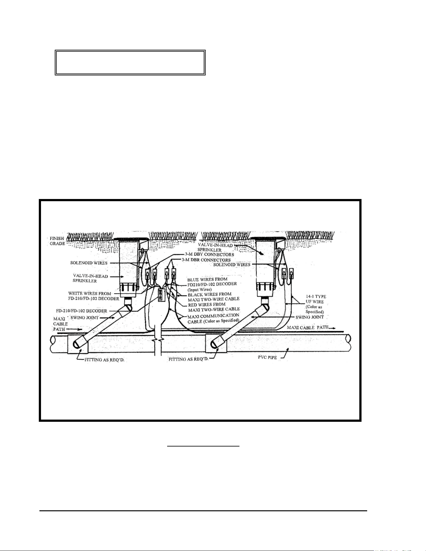
TWO SPRINKLERS OPERATING FROM ONE DECODER – Another method of control
on a single row fairway system is to operate and control two (2) sprinklers together form one
single decoder. This is illustrated below. Refer to FIGURE: 3.13below.
FIGURE: 3.13
A SINGLE FD-102 DECODER OPERATING
TWO VALVE-IN-HEAD SPRINKLERS

GT27141D Page 41 November 2003
LOCATION OF DECODER – Where two (2) Valve-in-Head sprinklers are to be operated
from a single FD-102 decoder, locate the decoder at the first Valve-in-Head in line. The wiring
procedure is similar to that for a remote control or “block” valve with the exception that the
decoder and splices will be directly buried beside the first Valve-in-Head sprinkler, instead of in
a valve box In addition there is a second Valve-in-Head sprinkler also being controlled by this
same decoder. It is important that the LOCATION OF THE DECODER AND SPLICES
REMAIN CONSISTENT through out the entire course. It is recommended that the assembly
be buried directly below the manual valve actuator 6” below grade. DO NOT TAPE the
decoder and splice assembly to the Valve-in-Head sprinkler, as this would prevent removal of
the sprinkler head from the riser without first digging down and un-taping the assembly.
Otherwise, the solenoid coil can just be slipped off the core tube and the sprinkler then can be
un-screwed from the riser. As with all splices, leave enough slack so as to be able to lift the
assembly at least 1’-0” above the finish grade. Orient the DBR’s and DBY’s above the decoder
and all the wires. In this way they will serve to protect the wires from being nicked, by alerting
you that you’re close to the wires if any digging is required in this area in the future.
FIRST – Strip the outer jacket from each end of the two-wire communication cable, where you
are going to install the decoder for the Valve-in-Head sprinkler. Refer to previous area
“Stripping the Outer Jacket”. Then from each end of the conductors in the communication
cable, strip approximately 5/8” of the PVC inner insulation from the conductors. Refer to
FIGURE: 3.7 shown previously, for proper type of wire stripper to use.
MAKING THE WIRE SPLICE – When making an inline wire splice use a linesman’s pliers
to gently twist one of the red insulated conductors to the other red insulated conductor and one of
the black insulate conductors to the other black insulated conductor. Place no more than three or
four twists in the wire. Twisting the wires in excess can fracture the conductors. Refer to
FIGURE: 3.8 shown previously.
WIRING OF DECODER INPUT & OUTPUT WIRES – The first in-line Valve-in-Head
Sprinkler will be wired to a FD-210/FD-102 decoder and the decoder in turn wired into the Two-
“Wire communication path. The two (2) blue input wires of the decoder connect into the Two-
Wire communication path, one to the RED insulated wires of the Two-Wire cable and the other
to the BLACK insulated wires of the cable. It does not matter which of the blue wires, from
the decoder, connect to the red and which to the black wires of the two-wire cable. The two
output decoder wires are white and each connects to one of the two wires coming from the
solenoid coil. In addition the solenoid at the second Valve-in-Head sprinkler (that is to be
controlled by this decoder) is to be connect to the decoder’s white output wires also. Splice a
pair of 14-1 wires into the connections between the white decoder output wires and the solenoid
wires for the first Valve-in-Head sprinkler. Use 3-M DBR connectors for these splices. This

GT27141C Page 42 November 2003
additional wire will run the distance between the first Valve-in-Head sprinkler and the second
Valve-in-Head sprinkler. Refer to FIGURE: 3.13 shown previously. Connect each of these
wires to the solenoid wires of the second Valve-in-Head sprinkler using 3-M DBY connectors..
Again it does not matter which of the wires from the decoder connect to which wires of the
solenoid coil. The procedures for proper splicing of an inline splice apply to all of these
splices.. It may be necessary to strip a small additional amount of the insulation from the blue
and white wires of the decoder as well as from the wires of the solenoid coil to provide enough
bare copper conductor to work with in making the splice. If this is a “retrofit” of an existing
system, this wire can be installed with a vibratory plow or if it is a new piping network, the
additional wire can be laid in the trench between the first and second Valve-in-Head sprinklers
and located as specified earlier in this manual
GT27141D Page 43 November 2003
CONFIGURATION #4:
ONE DECODER FD-102 CONTROLLING TWO
VALVE-IN-HEAD SPRINKLERS IN A BLOCK
CONFIGURATION
TWO VALVE-IN-HEAD SPRINKLERS IN “BLOCK” CONFIGURATION BEING
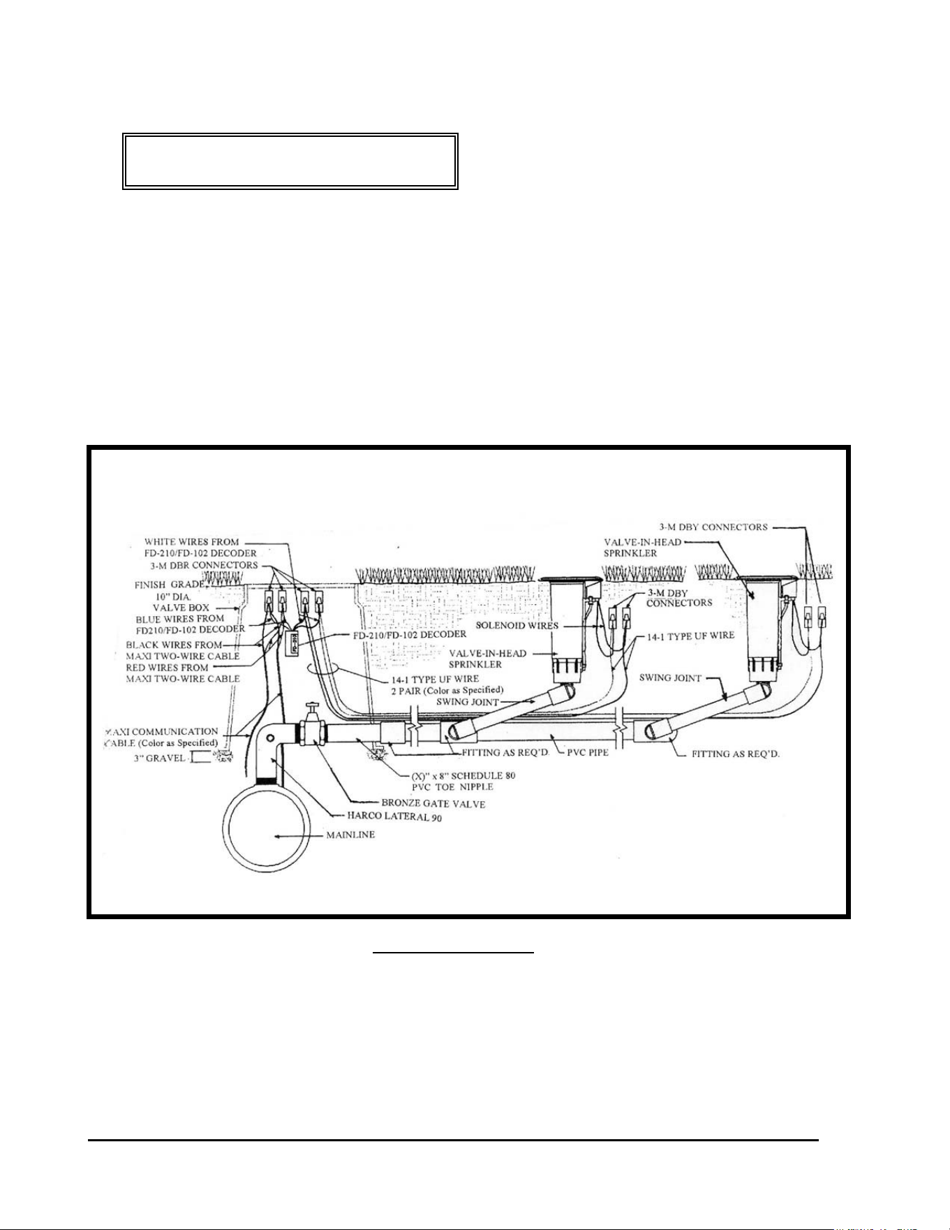
OPERATED FROM ONE DECODER – Another method of control of valve-in-head
sprinklers in a “block” configuration is the two operating together from one single decoder.
This is illustrated below. Refer to FIGURE: 3.14 below.
FIGURE: 3.14
LOCATION OF DECODER - Where two (2) Valve-in-Head sprinklers, in a “block
configuration,” are to be operated from a single FD-102 decoder, the decoder shall be located at
the mainline where the lateral line takes-off from it. The decoder and wire splices shall be
installed at this location in a 10” diameter valve box. Leave enough “slack” in the wires so that
the splices can be extended above the finish grade a minimum of 1’-0” for future ease of
maintenance.
TWO “BLOCK” CONFIGURATION VALVE-IN-HEAD SPRINKLERS
BEING CONTROLLED FROM ONE FD-102 DECODER

GT27141C Page 44 November 2003
At each of the Valve-in-Head sprinklers in the block the wire splices shall be directly buried
about 6” below finish grade and directly beneath the solenoid/actuator of the sprinkler. It is
important that the LOCATION OF THE SPLICES REMAIN CONSISTENT through out the
entire course. DO NOT TAPE the splice assembly to the Valve-in-Head sprinkler, as this
would prevent removal of the sprinkler head from the riser without first digging down and un-
taping the assembly. Otherwise, the solenoid coil can just be slipped off the core tube and the
sprinkler then can be un-screwed from the riser. As with all splices, leave enough slack so as to
be able to lift the assembly at least 1’-0” above the finish grade.
FIRST – Strip the outer jacket from each end of the two-wire communication cable, where you
are going to install the decoder, near the lateral take-off and which will control the “block”
configuration Valve-in-Head sprinklers. Refer to previous area “Stripping the Outer Jacket”.
Then from each end of the conductors in the communication cable, strip approximately 5/8” of
the PVC inner insulation from the conductors. Refer to FIGURE: 3.7 shown previously, for
proper type of wire stripper to use.
MAKING THE WIRE SPLICE – When making an inline wire splice use a linesman’s pliers
to gently twist one of the red insulated conductors to the other red insulated conductor and one of
the black insulate conductors to the other black insulated conductor. Place no more than three or
four twists in the wire. Twisting the wires in excess can fracture the conductors. Refer to
FIGURE: 3.8 shown previously.
WIRING OF DECODER INPUT & OUTPUT WIRES – The FD-102 decoder shall be wired
into the Two-“Wire communication path at this lateral take-off location. The two (2) blue input
wires of the decoder connect into the Two-Wire communication path, one to the RED insulated
wires of the Two-Wire cable and the other to the BLACK insulated wires of the cable. It does
not matter which of the blue wires, from the decoder, connect to the red and which to the black
wires of the two-wire cable. The two output decoder wires are white and each connects to one of
the two wires coming from each solenoid coil of the two (2) Valve-in-Head sprinklers being
controlled by this decoder. Splice two (2) pair of 14-1 wires to the two white decoder output
wires. Use 3-M DBR connectors for these splices. One pair, of these two (2) pair of wires,
will run the distance between the decoder and the first Valve-in-Head sprinkler of the block.
The second pair of wires will run the distance from the decoder to the second Valve-in-Head
sprinkler of the block. The maximum wire run between the decoder and the Valve-in-Head
sprinkler must not exceed 328 feet. Refer to FIGURE: 3.14 shown previously. Connect each
of the wires, in each pair, to their respective solenoid coils of the Valve-in-Head sprinklers
using a 3-M DBY connectors at each splice. Again it does not matter which of the wires from
the decoder connect to which wires of the solenoid coil as long as you keep the pairs straight.
(It is suggested that different color of wires be used for each pair for easy identification.) The
procedures for proper splicing of an inline splice apply to all of these splices.. It may be
necessary to strip a small additional amount of the insulation from the blue and white wires of
the decoder as well as from the wires of the solenoid coils to provide enough bare copper

GT27141D Page 45 November 2003
conductor to work with in making the splice. If this is a “retrofit” of an existing system, this
wire can be installed with a vibratory plow or if it is a new piping network, the additional wire
can be laid in the trench between the first and second Valve-in-Head sprinklers and located as
specified earlier in this manual
CHECKING THE WIRING – After you have made all the decoder output wire splices at the
solenoid coils at each of the two Valve-in-Head sprinklers but before connecting to the decoder,
check the resistance at the decoder end of these wires, using an OHM meter to measure the
resistance to make sure the wires are connected to the solenoid properly. You should have
approximately 24 to 29 Ohms of resistance. After the test then make the connections to
the decoder. For a proper installation you need to know which pair is connected to which
Valve-in-Head sprinkler on the lateral. Mark or Tag each pair accordingly for future reference.
CONNECTING THE DECODER OUTPUT –One of the 14-1 pair of UF wires coming from
the decoder white output wires are to be connected to the wires on the solenoid coil of the first
Valve-in-Head sprinkler of the block.. It may be necessary to strip a small amount of additional
insulation off the solenoid wires to provide enough bare copper conductor to work with in
making the splices. Take one of the wires in the 14-1 pair from the decoder output wires and
hold it parallel to one of the solenoid coil wires and using your fingers or a linesman’s pliers,
twist the two wires together. Use a CLOCKWISE direction in making the twist so that in
applying the wire nut it will not cause the wires to “un-twist”. Repeat this procedure for the
other wire in the pair from the decoder output wires and the remaining solenoid coil wire. Place
a wire nut on each of these splices and then insert each splice into a
3-M DBY connector, making sure you insert it into the connector as far as possible, and then
snap the cap securely in place. Refer to FIGURE: 3.10 shown previously and also FIGURE
3.12 shown previously.
The second 14-1 pair of UF wires coming from the decoder white output wires are to be
connected to the wires on the solenoid coil of the second Valve-in-Head sprinkler of the block..
It may be necessary to strip a small amount of additional insulation off the solenoid wires to
provide enough bare copper conductor to work with in making the splices. Take one of the
wires in the 14-1 pair from the decoder output wires and hold it parallel to one of the solenoid
coil wires and using your fingers or a linesman’s pliers, twist the two wires together. Use a
CLOCKWISE direction in making the twist so that in applying the wire nut it will not cause
the wires to “un-twist”. Repeat this procedure for the other wire in the pair from the decoder
output wires and the remaining solenoid coil wire. Place a wire nut on each of these splices and
then insert each splice into a 3-M DBY connector, making sure you insert it into the
connector as far as possible, and then snap the cap securely in place. Refer to FIGURE: 3.10
shown previously and also FIGURE 3.12 shown previously.
GT27141C Page 46 November 2003
T
CONFIGURATION #5:
FD-202 DECODER CONTROLLING TWO
VALVE-IN-HEAD SPRINKLERS INDEPENDENTLY IN
A BLOCK CONFIGURATION
TWO VALVE-IN-HEAD SPRINKLERS IN “BLOCK” CONFIGURATION
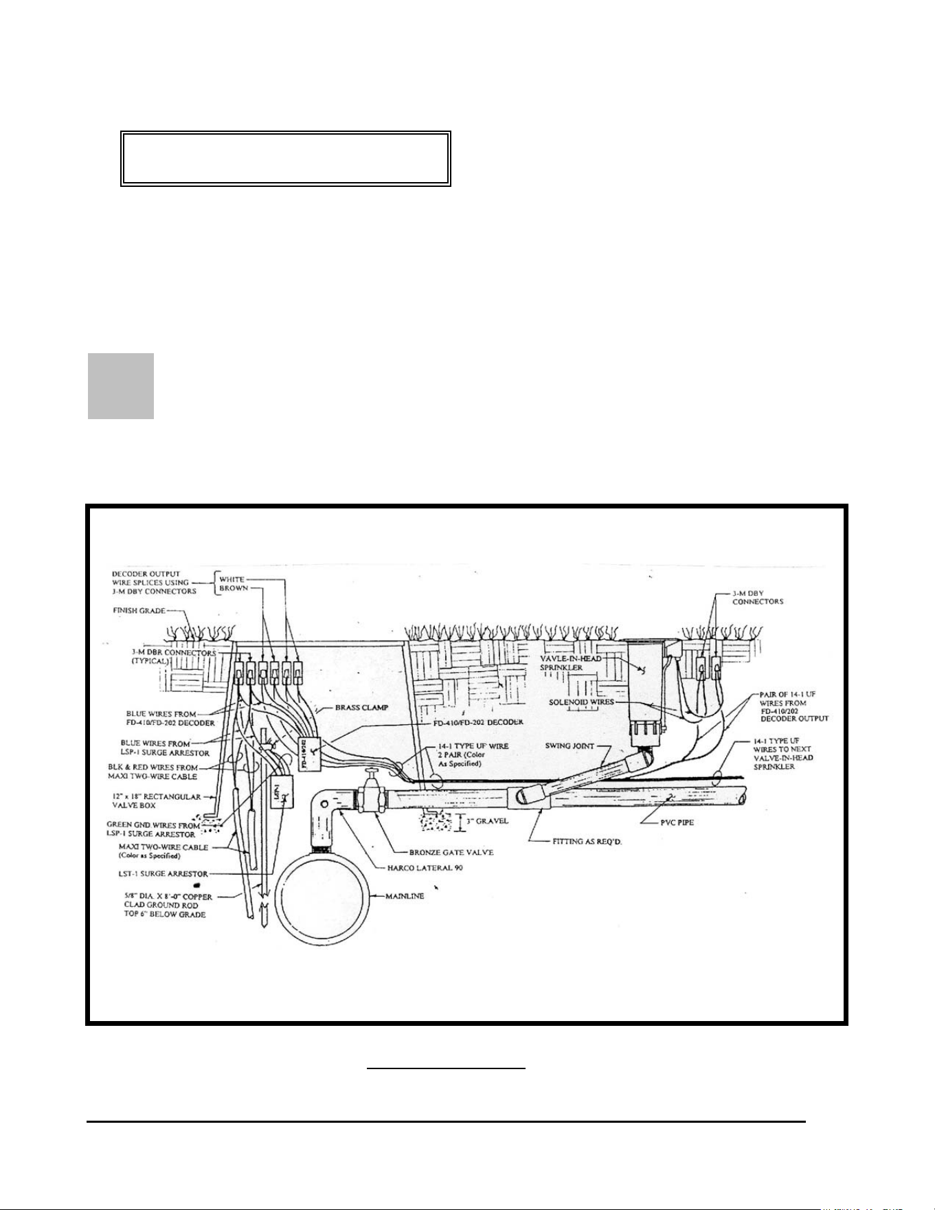
BEING INDIVIDUALLY OPERATED FROM ONE DECODER – Another
method of control of valve-in-head sprinklers in a “block” configuration is the two operating
independently from one single decoder. This is illustrated below. Refer to FIGURE: 3.15
below.
FIGURE: 3.15
TWO “BLOCK” CONFIGURATION VALVE-IN-HEAD SPRINKLERS
BEING CONTROLLED FROM ONE FD-202 DECODER

GT27141D Page 47 November 2003
LOCATION OF DECODER - Where two (2) Valve-in-Head sprinklers, in a “block
configuration,” are to be operated from a single FD-202 decoder, the decoder shall be located at
the mainline where the lateral line takes-off from it. The decoder and wire splices shall be
installed at this location in a 12” x 18” or larger, rectangular valve box. Leave enough “slack”
in the wires so that the splices can be extended above the finish grade a minimum of 1’-0” for
future ease of maintenance.
At each of the Valve-in-Head sprinklers, in the block, the wire splices shall be directly buried
about 6” below finish grade and directly beneath the solenoid/actuator of the sprinkler. It is
important that the LOCATION OF THE SPLICES REMAIN CONSISTENT through out the
entire course. DO NOT TAPE the splice assembly to the Valve-in-Head sprinkler, as this
would prevent removal of the sprinkler head from the riser without first digging down and un-
taping the assembly. Otherwise, the solenoid coil can just be slipped off the core tube and the
sprinkler then can be un-screwed from the riser. As with all splices, leave enough slack so as to
be able to lift the assembly at least 1’-0” above the finish grade.
FIRST – Strip the outer jacket from each end of the two-wire communication cable, where you
are going to install the decoder, near the lateral take-off and which will control the “block”
configuration Valve-in-Head sprinklers. Refer to previous area “Stripping the Outer Jacket”.
Then from each end of the conductors in the communication cable, strip approximately 5/8” of
the PVC inner insulation from the conductors. Refer to FIGURE: 3.7 shown previously, for
proper type of wire stripper to use.
MAKING THE WIRE SPLICE – When making an inline wire splice use a linesman’s pliers
to gently twist one of the red insulated conductors to the other red insulated conductor and one of
the black insulate conductors to the other black insulated conductor. Place no more than three or
four twists in the wire. Twisting the wires in excess can fracture the conductors. Refer to
FIGURE: 3.8 shown previously.
WIRING OF DECODER INPUT & OUTPUT WIRES – The FD-401 decoder shall be wired
into the Two-“Wire communication path at this lateral take-off location.
DECODER INPUT WIRING: The two (2) blue input wires of the decoder connect
into the Two-Wire communication path, one to the RED insulated wires of the Two-Wire
cable and the other to the BLACK insulated wires of the cable. It does not matter which of the
blue wires, from the decoder, connect to the red and which to the black wires of the two-wire
cable. In addition; the two (2) green ground wires from the decoder should be attached to a
ground rod at this location. Use 3-M DBR connectors for these splices. Refer to FIGURE:
3.15 shown previously.

GT27141C Page 48 November 2003
DECODER OUTPUT WIRING: There are two pair of output decoder wires from this
decoder. One pair are white and the other pair are brown. One pair are to be connected to the
two solenoid wires coming from the solenoid coil of one of the two (2) Valve-in-Head sprinklers
being controlled by this decoder. The second pair are to be connected to the two solenoid wires
coming from the solenoid coil of the other Valve-in-Head sprinkler. The maximum wire run
between the decoder and the Valve-in-Head sprinkler must not exceed 328 feet. In order to
make these connections it is necessary to splice a pair of 14-1 wires into each of the decoder
output pair of wires. In order to keep the wires identified for each of the sprinklers, use a
different color of wire for each of the pairs. Take one of the wires in the one 14-1 pair and one
of the brown decoder output wires and hold them parallel to each other. Using your fingers or a
linesman’s pliers, twist the two wires together. Use a CLOCKWISE direction in making the
twist so that in applying the wire nut it will not cause the wires to “un-twist”. Use a 3-M
DBY connector for this splice. The other wire of this pair and the other brown decoder wires
shall be spliced together in the same manner. Repeat this same process for the wires in the
second 14-1 pair of wires and the two white decoder output wires. One pair of these two (2) pair
of wires, will run the distance between the decoder and the first Valve-in-Head sprinkler of the
block. The second pair of wires will run the distance from the decoder to the second Valve-in-
Head sprinkler of the block. Refer to FIGURE: 3.15 shown previously.
SPRINKLER SOLENOID WIRING: At the first Valve-in-Head sprinkler, connect each of
the wires, in the pair controlling this sprinkler, to the respective solenoid coil wires of the
Valve-in-Head sprinklers. Again it does not matter which of the wires from the decoder connect
to which wires of the solenoid coil as long as you keep the pairs straight. (It is suggested that
different color of wires be used for each pair for easy identification.) Take one of the wires in
the 14-1 pair and one of the wires from the solenoid coil and hold them parallel to each other.
Using your fingers or a linesman’s pliers, twist the two wires together. Use a CLOCKWISE
direction in making the twist so that in applying the wire nut it will not cause the wires to “un-
twist”. . Place a wire nut on the splice and then insert the splice into a 3-M DBY connector,
making sure you insert it into the connector as far as possible, and then snap the cap securely in
place. Refer to FIGURE: 3.10 shown previously and also FIGURE 3.15 shown previously.
Repeat this procedure for the second wire of this pair and the remaining solenoid coil wire.
At the second Valve-in-Head sprinkler, connect each of the wires, in the pair controlling this
sprinkler, to the respective solenoid coil wires of the Valve-in Head sprinkler. Follow the same
procedure as outlined immediately above. The procedures for proper splicing of an inline splice
apply to all of these splices.. It may be necessary to strip a small additional amount of the
insulation from the wires of the solenoid coils to provide enough bare copper conductor to work
with in making the splice. If this is a “retrofit” of an existing system, this wire can be installed
with a vibratory plow or if it is a new piping network, the additional wire can be laid in the
trench between the decoder location and the first and second Valve-in-Head sprinklers. Locate
and install the wire in the trench, as specified earlier in this manual
CHECKING THE WIRING – After you have made all the decoder output wire splices, at the
solenoid coils at each of the Valve-in-Head sprinklers but before connecting to the decoder,
check the resistance, at the decoder end of these wires, using an OHM meter to measure the

GT27141D Page 49 November 2003
resistance to make sure the wires are connected to the solenoid properly. You should have
approximately 24 to 29 Ohms of resistance. For a proper installation you need to know
which pair is connected to which Valve-in-Head sprinkler on the lateral. Mark or Tag each pair
accordingly for future reference.
RECORDING OF DECODER ADDRESS CODE – At this point, record the four or five
digit decoder address codes, for this decoder. (Remember that there are TWO (2)
ADDRESSES for this decoder). You must not only identify the correct address code but also
indicate which of the Valve-in-Head sprinklers the address is controlling. This data needs to be
recorded on either a “Start-Up Work Sheet” and/or on a drawing of the irrigation system layout
for the course, making sure you identify the proper location in the field for this decoder and of
the sprinklers. This data will need to be on the “Start-Up Work Sheet” along with all the other
necessary information to do the initial data entry into the computer. The decoders can be
installed in any random address code order and do not need to be installed sequentially. The
important thing is to accurately record the address code for the proper decoder and to
properly identify the corresponding sprinkler this address will control.
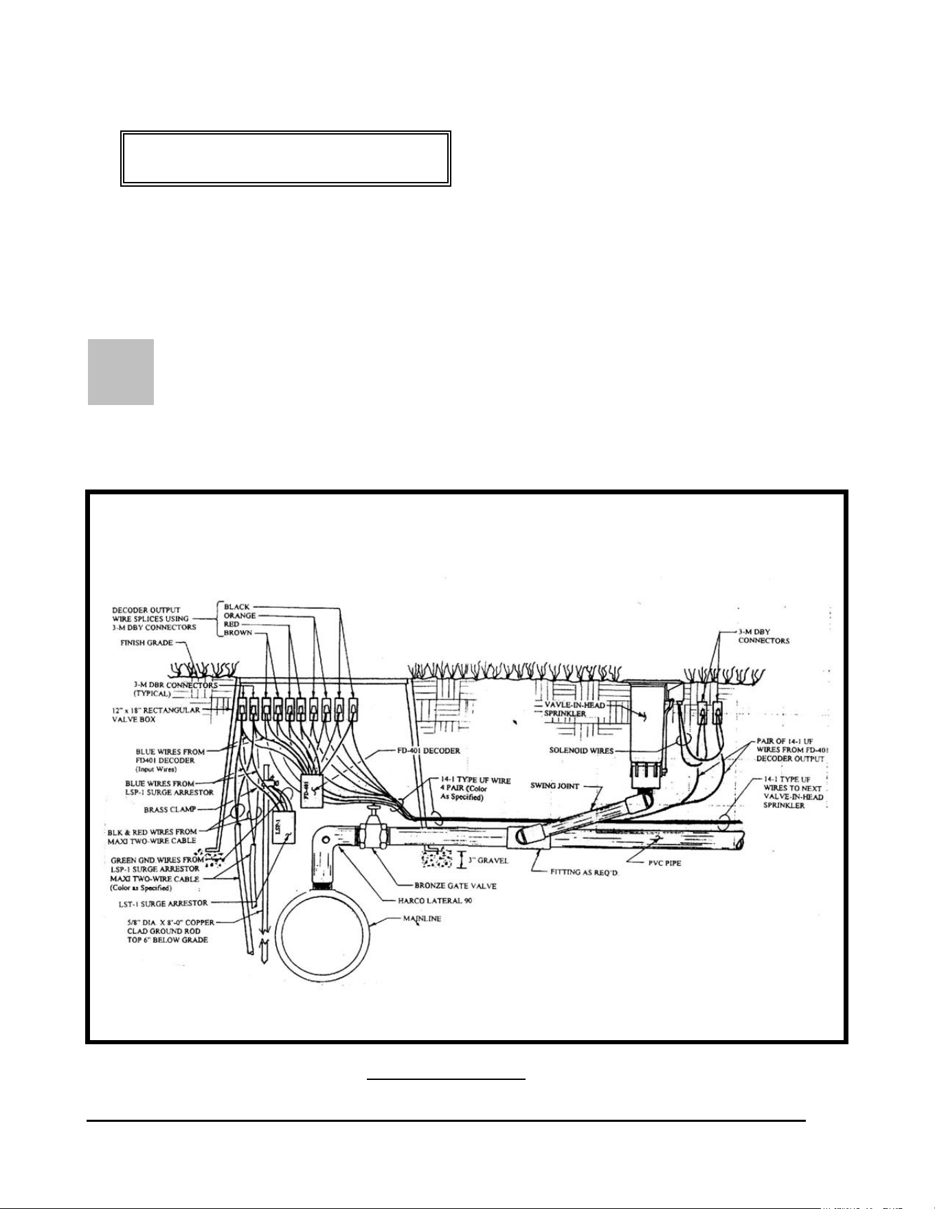
GT27141C Page 50 November 2003
F
CONFIGURATION #6:
FD-401 DECODER CONTROLLING FOUR
VALVE-IN-HEAD SPRINKLERS INDEPENDENTLY IN
A BLOCK CONFIGURATION
OUR VALVE-IN-HEAD SPRINKLERS IN “BLOCK” CONFIGURATION
BEING INDIVIDUALLY OPERATED FROM ONE DECODER – Using an FD-
401 decoder four valve-in-head sprinklers, in a “block” configuration, can each be operated
independently from one single decoder. This is illustrated below. Refer to FIGURE: 3.16
below.
FIGURE: 3.16
FOUR “BLOCK” CONFIGURATION VALVE-IN-HEAD SPRINKLERS
BEING INDEPENDENTLY CONTROLLED FROM
ONE FD-401 DECODER

GT27141D Page 51 November 2003
LOCATION OF DECODER - Where four (4) Valve-in-Head sprinklers, in a “block
configuration,” are to be operated from a single FD-401 decoder, the decoder shall be located at
the mainline where the lateral line takes-off from it. The decoder and wire splices shall be
installed at this location in a 12” x 18” or larger, rectangular valve box. Leave enough “slack”
in the wires so that the splices can be extended above the finish grade a minimum of
1’-0” for future ease of maintenance.
At each of the Valve-in-Head sprinklers, in the block, the wire splices shall be directly buried
about 6” below finish grade and directly beneath the solenoid/actuator of the sprinkler. It is
important that the LOCATION OF THE SPLICES REMAIN CONSISTENT through out the
entire course. DO NOT TAPE the splice assembly to the Valve-in-Head sprinkler, as this
would prevent removal of the sprinkler head from the riser without first digging down and un-
taping the assembly. Otherwise, the solenoid coil can just be slipped off the core tube and the
sprinkler then can be un-screwed from the riser. As with all splices, leave enough slack so as to
be able to lift the assembly at least 1’-0” above the finish grade.
FIRST – Strip the outer jacket from each end of the two-wire communication cable, where you
are going to install the decoder, near the lateral take-off and which will control the “block”
configuration Valve-in-Head sprinklers. Refer to previous area “Stripping the Outer Jacket”.
Then from each end of the conductors in the communication cable, strip approximately 5/8” of
the PVC inner insulation from the conductors. Refer to FIGURE: 3.7 shown previously, for
proper type of wire stripper to use.
MAKING THE WIRE SPLICE – When making an inline wire splice use a linesman’s pliers
to gently twist one of the red insulated conductors to the other red insulated conductor and one of
the black insulate conductors to the other black insulated conductor. Place no more than three or
four twists in the wire. Twisting the wires in excess can fracture the conductors. Refer to
FIGURE: 3.8 shown previously.
WIRING OF DECODER INPUT & OUTPUT WIRES – The FD-401 decoder shall be wired
into the Two-“Wire communication path at this lateral take-off location.
DECODER INPUT WIRING: The two (2) blue input wires of the decoder
connect into the Two-Wire communication path, one to the RED insulated wires
of the Two-Wire cable and the other to the BLACK insulated wires of the cable. It does not
matter which of the blue wires, from the decoder, connect to the red and which to the black
wires of the two-wire cable. In addition; the two (2) green ground wires from the decoder
should be attached to a ground rod at this location. Use 3-M DBR connectors for these splices.
Refer to FIGURE: 3.16 shown previously.

GT27141C Page 52 November 2003
DECODER OUTPUT WIRING: There are four (4) pair of output decoder wires from this
decoder, a brown, red, orange and a black pair.. One pair are to be connected to the two
solenoid wires coming from the solenoid coil of one of the four (4) Valve-in-Head sprinklers
being controlled by this decoder. The second pair are to be connected to the two solenoid wires
coming from the solenoid coil of the second Valve-in-Head sprinkler. The third pair are to be
connected to the two solenoid wires coming from the solenoid coil of the third Valve-in-Head
sprinkler. The fourth pair are to be connected to the two solenoid wires coming from the
solenoid coil of the fourth Valve-in-Head sprinkler. The maximum wire run between the
decoder and any of the Valve-in-Head sprinklers must not exceed 328 feet. In order to make
these connections it is necessary to splice a pair of 14-1 wires into each of the decoder output
pair of wires. In order to keep the wires identified for each of the sprinklers, use a different
color of wire for each of the pairs. Take one of the wires in the one 14-1 pair and one of the
brown decoder output wires and hold them parallel to each other. Using your fingers or a
linesman’s pliers, twist the two wires together. Use a CLOCKWISE direction in making the
twist so that in applying the wire nut it will not cause the wires to “un-twist”. Use a 3-M
DBY connector for this splice. The other wire of this pair and the other brown decoder wire
shall be spliced together in the same manner. Repeat this same process for the wires in the
second, third and fourth 14-1 pair of wires and to the two red, orange and black decoder output
wire pairs. One pair of these four (4) pair of wires, will run the distance between the decoder
and the first Valve-in-Head sprinkler of the block. The second pair of wires will run the
distance from the decoder to the second Valve-in-Head sprinkler of the block. The third pair of
wires will run the distance from the decoder to the third Valve-in-Head sprinkler of the block.
The fourth pair of wires will run the distance form the decoder to the fourth Valve-in-Head
sprinkler of the block. Refer to FIGURE: 3.16 shown previously.
SPRINKLER SOLENOID WIRING: At the first Valve-in-Head sprinkler, connect each of
the wires, in the pair controlling this sprinkler, to the respective solenoid coil wires of the
Valve-in-Head sprinklers. Again it does not matter which of the wires from the decoder connect
to which wires of the solenoid coil as long as you keep the pairs straight. (It is suggested that
different color of wires be used for each pair for easy identification.) Take one of the wires in
the 14-1 pair and one of the wires from the solenoid coil and hold them parallel to each other.
Using your fingers or a linesman’s pliers, twist the two wires together. Use a CLOCKWISE
direction in making the twist so that in applying the wire nut it will not cause the wires to “un-
twist”. . Place a wire nut on the splice and then insert the splice into a 3-M DBY connector,
making sure you insert it into the connector as far as possible, and then snap the cap securely in
place. Refer to FIGURE: 3.10 shown previously and also FIGURE 3.16 shown previously.
Repeat this procedure for the second wire of this pair and the remaining solenoid coil wire.
At the second Valve-in-Head sprinkler, connect each of the wires, in the pair controlling this
sprinkler, to the respective solenoid coil wires of the Valve-in Head sprinkler. Follow the same
procedure as outlined immediately above. Do the same at the third and fourth Valve-in-Head
sprinklers. The procedures for proper splicing of an inline splice apply to all of these splices..
It may be necessary to strip a small additional amount of the insulation from the wires of the
solenoid coils to provide enough bare copper conductor to work with in making the splice. If
this is a “retrofit” of an existing system, this wire can be installed with a vibratory plow or if it is

GT27141D Page 53 November 2003
a new piping network, the additional wire can be laid in the trench between the decoder location
and the first, second, third and fourth Valve-in-Head sprinklers. Locate and install the wire in
the trench, as specified earlier in this manual
CHECKING THE WIRING – After you have made all the decoder output wire splices, at the
solenoid coils at each of the Valve-in-Head sprinklers but before connecting to the decoder,
check the resistance, at the decoder end of these wires, using an OHM meter to measure the
resistance to make sure the wires are connected to the solenoid properly. You should have
approximately 24 to 29 Ohms of resistance. For a proper installation you need to know
which pair is connected to which Valve-in-Head sprinkler on the lateral. Mark or Tag each pair
accordingly for future reference.
RECORDING OF DECODER ADDRESS CODE – At this point, record the four or five
digit decoder address codes, for this decoder. (Remember that there are FOUR (4)
ADDRESSES for this decoder). You must not only identify the correct address code but also
indicate which of the Valve-in-Head sprinklers the address is controlling. This data needs to be
recorded on either a “Start-Up Work Sheet” and/or on a drawing of the irrigation system layout
for the course, making sure you identify the proper location in the field for this decoder and of
the sprinklers. This data will need to be on the “Start-Up Work Sheet” along with all the other
necessary information to do the initial data entry into the computer. The decoders can be
installed in any random address code order and do not need to be installed sequentially. The
important thing is to accurately record the address code for the proper decoder and to
properly identify the corresponding sprinkler this address will control.
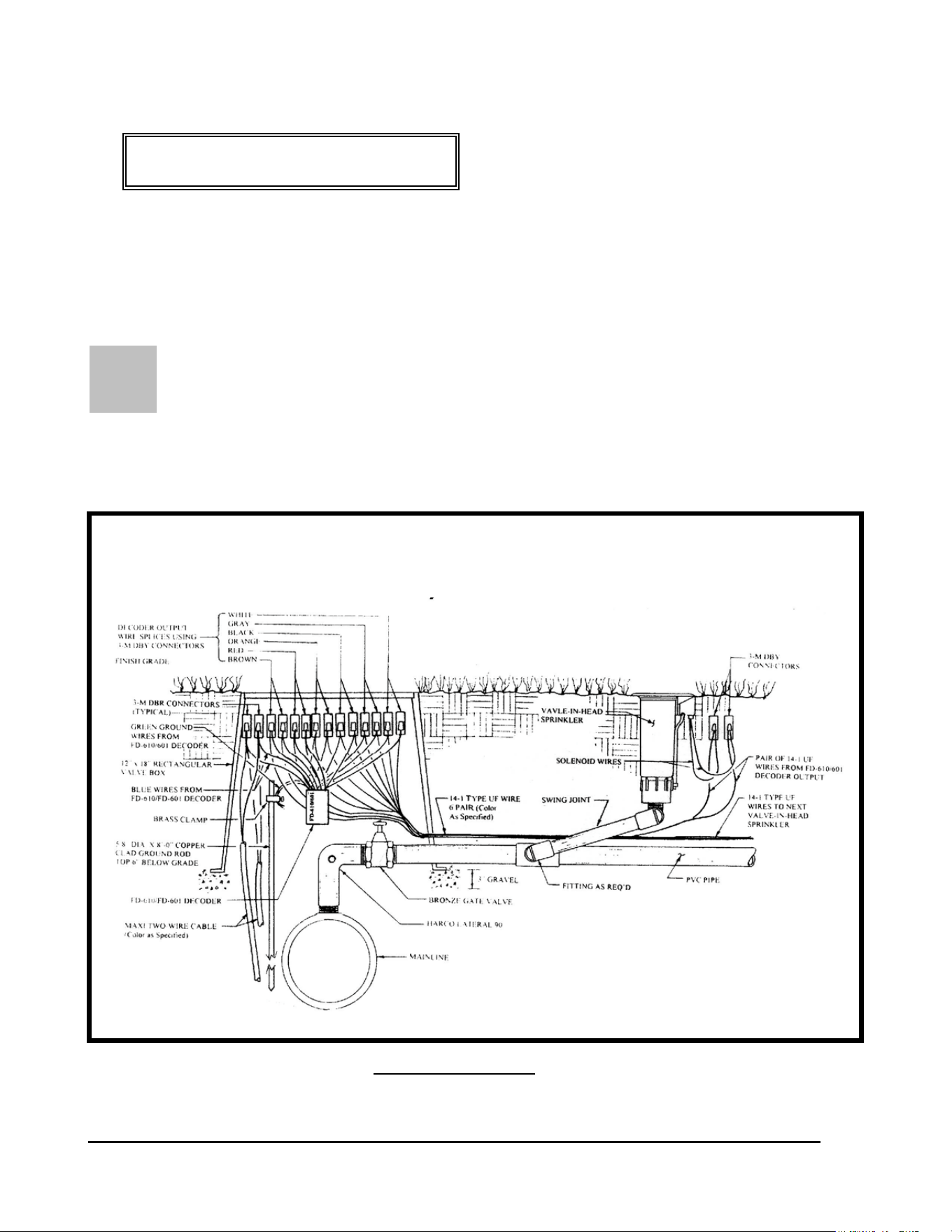
GT27141C Page 54 November 2003
S
CONFIGURATION #7:
FD-601 DECODER CONTROLLING SIX
VALVE-IN-HEAD SPRINKLERS INDEPENDENTLY IN
A BLOCK CONFIGURATION
IX VALVE-IN-HEAD SPRINKLERS IN “BLOCK” CONFIGURATION
BEING INDIVIDUALLY OPERATED FROM ONE DECODER – Using an FD-
601 decoder SIX valve-in-head sprinklers, in a “block” configuration, can each be operated
independently from one single decoder. This is illustrated below. Refer to FIGURE: 3.17
below.
FIGURE: 3.17
SIX “BLOCK” CONFIGURATION VALVE-IN-HEAD SPRINKLERS
BEING INDEPENDENTLY CONTROLLED FROM
ONE FD-601 DECODER

GT27141D Page 55 November 2003
LOCATION OF DECODER - Where six (6) Valve-in-Head sprinklers, in a “block
configuration,” are to be operated from a single FD-601 decoder, the decoder shall be located at
the mainline where the lateral line takes-off from it. The decoder and wire splices shall be
installed at this location in a 12” x 18” or larger, rectangular valve box. Leave enough “slack”
in the wires so that the splices can be extended above the finish grade a minimum of 1’-0” for
future ease of maintenance.
At each of the Valve-in-Head sprinklers, in the block, the wire splices shall be directly buried
about 6” below finish grade and directly beneath the solenoid/actuator of the sprinkler. It is
important that the LOCATION OF THE SPLICES REMAIN CONSISTENT through out the
entire course. DO NOT TAPE the splice assembly to the Valve-in-Head sprinkler, as this
would prevent removal of the sprinkler head from the riser without first digging down and un-
taping the assembly. Otherwise, the solenoid coil can just be slipped off the core tube and the
sprinkler then can be un-screwed from the riser. As with all splices, leave enough slack so as to
be able to lift the assembly at least 1’-0” above the finish grade.
FIRST – Strip the outer jacket from each end of the two-wire communication cable, where you
are going to install the decoder, near the lateral take-off and which will control the “block”
configuration Valve-in-Head sprinklers. Refer to previous area “Stripping the Outer Jacket”.
Then from each end of the conductors in the communication cable, strip approximately 5/8” of
the PVC inner insulation from the conductors. Refer to FIGURE: 3.7 shown previously, for
proper type of wire stripper to use.
MAKING THE WIRE SPLICE – When making an inline wire splice use a linesman’s pliers
to gently twist one of the red insulated conductors to the other red insulated conductor and one of
the black insulate conductors to the other black insulated conductor. Place no more than three or
four twists in the wire. Twisting the wires in excess can fracture the conductors. Refer to
FIGURE: 3.8 shown previously.
WIRING OF DECODER INPUT & OUTPUT WIRES – The FD-601 decoder shall be wired
into the Two-“Wire communication path at this lateral take-off location.
DECODER INPUT WIRING: The two (2) blue input wires of the decoder connect into the
Two-Wire communication path, one to the RED insulated wires of the Two-Wire cable and the
other to the BLACK insulated wires of the cable. It does not matter which of the blue wires,
from the decoder, connect to the red and which to the black wires of the two-wire cable. In
addition; the two (2) green ground wires from the decoder should be attached to a ground rod at
this location. Use 3-M DBR connectors for these splices. Refer to FIGURE: 3.16 shown
previously.

GT27141C Page 56 November 2003
DECODER OUTPUT WIRING: There are six (6) pair of output decoder wires from this
decoder, a brown, red, orange, black, gray and white pair.. One pair are to be connected to
the two solenoid wires coming from the solenoid coil of the first Valve-in-Head sprinkler of the
six (6) Valve-in-Head sprinklers being controlled by this decoder. The second pair are to be
connected to the two solenoid wires coming from the solenoid coil of the second Valve-in-Head
sprinkler. The third pair are to be connected to the two solenoid wires coming from the solenoid
coil of the third Valve-in-Head sprinkler. The fourth pair are to be connected to the two solenoid
wires coming from the solenoid coil of the fourth Valve-in-Head sprinkler. The fifth pair are to
be connected to the two solenoid wires coming from the solenoid coil of the fifth Valve-in-Head
sprinkler. The sixth pair are to be connected to the two solenoid wires coming from the solenoid
coil of the sixth Valve-in-Head sprinkler. The maximum wire run between the decoder and any
of the Valve-in-Head sprinklers must not exceed 328 feet. In order to make these connections it
is necessary to splice a pair of 14-1 wires into each of the decoder output pair of wires. In order
to keep the wires identified for each of the sprinklers, use a different color of wire for each of
the pairs. Take one of the wires in the one 14-1 pair and one of the brown decoder output wires
and hold them parallel to each other. Using your fingers or a linesman’s pliers, twist the two
wires together. Use a CLOCKWISE direction in making the twist so that in applying the wire
nut it will not cause the wires to “un-twist”. Use a 3-M DBY connector for this splice. The
other wire of this pair and the other brown decoder wire shall be spliced together in the same
manner. Repeat this same process for the wires in the second, third, fourth, fifth and sixth 14-1
pair of wires and to the two red, orange black, gray and white decoder output wire pairs. One
pair of these six (6) pair of wires, will run the distance between the decoder and the first Valve-
in-Head sprinkler of the block. The second pair of wires will run the distance from the decoder
to the second Valve-in-Head sprinkler of the block. The third pair of wires will run the distance
from the decoder to the third Valve-in-Head sprinkler of the block. The fourth pair of wires will
run the distance form the decoder to the fourth Valve-in-Head sprinkler of the block. The fifth
pair of wires will run the distance from the decoder to the fifth Valve-in-Head sprinkler of the
block. The sixth pair of wires will run the distance form the decoder to the sixth Valve-in-Head
sprinkler of the block. Refer to FIGURE: 3.17 shown previously.
SPRINKLER SOLENOID WIRING: At the first Valve-in-Head sprinkler, connect each of
the wires, in the pair controlling this sprinkler, to the respective solenoid coil wires of the
Valve-in-Head sprinklers. Again it does not matter which of the wires from the decoder connect
to which wires of the solenoid coil as long as you keep the pairs straight. (It is suggested that
different color of wires be used for each pair for easy identification.) Take one of the wires in
the 14-1 pair and one of the wires from the solenoid coil and hold them parallel to each other.
Using your fingers or a linesman’s pliers, twist the two wires together. Use a CLOCKWISE
direction in making the twist so that in applying the wire nut it will not cause the wires to “un-
twist”. . Place a wire nut on the splice and then insert the splice into a 3-M DBY connector,
making sure you insert it into the connector as far as possible, and then snap the cap securely in
place. Refer to FIGURE: 3.10 shown previously and also FIGURE 3.16 shown previously.
Repeat this procedure for the second wire of this pair and the remaining solenoid coil wire.
At the second Valve-in-Head sprinkler, connect each of the wires, in the pair controlling this
sprinkler, to the respective solenoid coil wires of the Valve-in Head sprinkler. Follow the same

GT27141D Page 57 November 2003
procedure as outlined immediately above. Do the same at the third, fourth, fifth and sixth
Valve-in-Head sprinklers. The procedures for proper splicing of an inline splice apply to all of
these splices.. It may be necessary to strip a small additional amount of the insulation from the
wires of the solenoid coils to provide enough bare copper conductor to work with in making the
splice. If this is a “retrofit” of an existing system, this wire can be installed with a vibratory
plow or if it is a new piping network, the additional wire can be laid in the trench between the
decoder location and the first, second, third and fourth Valve-in-Head sprinklers. Locate and
install the wire in the trench, as specified earlier in this manual
CHECKING THE WIRING – After you have made all the decoder output wire splices, at the
solenoid coils at each of the Valve-in-Head sprinklers but before connecting to the decoder,
check the resistance, at the decoder, using an OHM meter to measure the resistance to make sure
the wires are connected to the solenoid properly. You should have approximately 24 to 29
Ohms
of resistance. For a proper installation you need to know which pair is connected to
which Valve-in-Head sprinkler on the lateral. Mark or Tag each pair accordingly for future
reference.
RECORDING OF DECODER ADDRESS CODE – At this point, record the four or five
digit decoder address codes, for this decoder. (Remember that there are SIX (6) ADDRESSES
for this decoder). You must not only identify the correct address code but also indicate which of
the Valve-in-Head sprinklers the address is controlling. This data needs to be recorded on either
a “Start-Up Work Sheet” and/or on a drawing of the irrigation system layout for the course,
making sure you identify the proper location in the field for this decoder and of the sprinklers.
This data will need to be on the “Start-Up Work Sheet” along with all the other necessary
information to do the initial data entry into the computer. The decoders can be installed in any
random address code order and do not need to be installed sequentially. The important thing is
to accurately record the address code for the proper decoder and to properly identify the
corresponding sprinkler this address will control.

GT27141C Page 58 November 2003
Chapter
4
Surge Protection and Proper
Grounding of the Central Equipment
of the Decoder System
Proper Surge Protection and Proper Grounding of the Decoder System
Is Key to the Long and Trouble Free Operation of your System.
In order to provide a reasonable level of surge protection at a realistic and acceptable cost, it is
recommended that the following guidelines be followed in the installation of the Rain Bird
Decoder control system. Special attention needs to be giving to proper protection of the Central
Control Equipment and also of the various field decoders and other devices that make up the
complete system. Special attention and care should be taken in regard to the furnishing of the
recommended surge protection devices and the installation of these devices. Also, of equal
importance are the proper grounding of the surge protection devices and the proper grounding of
the equipment itself. For these devices to remain effective it is absolutely necessary to
properly maintain GOOD grounds for these devices and the equipment. Therefore, this
requires periodic checking of the grounds with a ground measuring instrument and the proper
maintenance of the grounding networks at all times. The importance of this cannot be over
stressed and should not be overlooked as a standard maintenance procedure of your system.
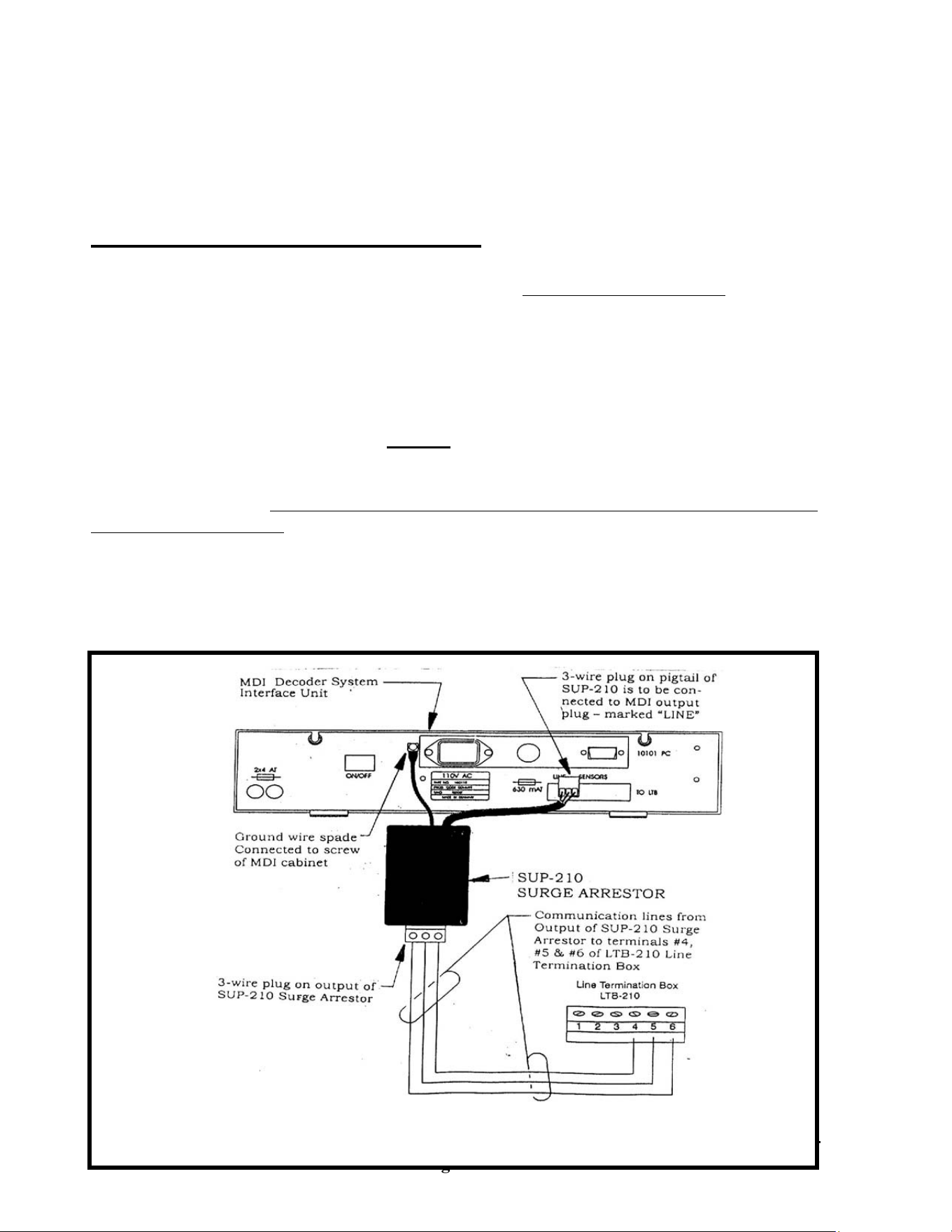
GT27141D Page 59 November 2003
*SEE ADDENDUM FOR LDI & SDI
MDI DECODER SYSTEM INTERFACE UNIT SURGE PROTECTION – For surge
protection of the MDI Unit (Decoder Interface Unit) install a Rain Bird Model SUP-210 Surge
Arrestor (which is included with the MDI unit) on the communication output of this unit and
before the communication wires connects to the LTB (Line Termination Box). Refer to
FIGURE: 4.1 shown below.
The 3-wire plug on the wire pigtail of the SUP-210 unit shall be plugged directly into the output
port of the MDI unit, which is marked “LINE”. The Yellow & Green striped ground wire with
spade lug shall have the spade lug connected to the screw on the MDI unit. Be careful to be
sure that this lug is securely tightened to the cabinet of the MDI unit and that the spring
washer is still there. This should also be periodically checked to be sure that it is still tightly
connected to the cabinet. Good physical contact of the spade, on this ground wire, with the
cabinet of the MDI, is essential to provide proper surge protection.
Connect the communication wires to the 3-wire plug on the outlet end of the SUP-210 Surge
Arrestor and extend them over and connect them to the terminals #4, #5 & #6 on the LTB-210
(Line Termination Box). Refer to FIGURE: 4.1 shown below.
INSTALLATION OF SUP-210 SURGE ARRESTOR FOR MDI UNIT

GT27141C Page 60 November 2003
FIGURE: 4.1

GT27141D Page 61 November 2003
MAINTAINING A GOOD GROUND: The success and the level of protection that will
actually be realized from the various surge arrestor devices is dependent upon the equality of
grounding that is achieved and MAINTAINED. Proper grounding is required to allow all
components to go to the same potential voltage level. Unless the surge arrestor can discharge
the surge to earth ground, it is ineffective in preventing the surge voltage from entering the
electronic components and damaging them. The surge will take the least path of resistance and
electronic components offer very little resistance. Therefore, the resistance of the path to earth
ground for the surge arrestors must be as low as possible. Anything greater than 15Ω (Ohms) is
ineffective and for greatest effectiveness the resistance to ground should be 5Ω (Ohms) or less,
if at all possible.
In cases where a surge or high potential is induced on one area of the system it is important that
other areas also go to this same potential. This is in order to avoid surge damage occurring
from the surge going from the high potential area to the low potential area. This is
accomplished again by the grounding system providing the necessary path to let both areas go to
the same potential level.
Central Control Equipment Grounding Network
Before any of the Central Control Equipment is installed and particularly before it is connected
to the field wiring, it is necessary to install a ground grid consisting of four (4) 5/8” dia. x 8’-0”
long, copper clad ground rods. Refer to FIGURE: 4.2 shown below. The purpose of this grid
is to provide a path to ground for any electrical surges that may try to enter the central
equipment. The grounding grid resistance must not exceed 15Ω (Ohms) or it will not be
effective in providing the necessary path to earth ground. The most effective ground grid
protecting central equipment should have a resistance of 5Ω (Ohms) or less, if at all possible.
This resistance level will not be obtained when the grid is first installed but is the objective after
a period of time and when the central equipment is ready to be installed and/or connected to the
field. Upon initial installation the ground rods will not have had a chance to make good contact
with the earth. Therefore, we recommend that the grid be installed four to five weeks prior to
the central equipment being connected to the field. While nothing can protect against a direct
lightning strike, grounding effectiveness goes down as resistance goes up. Just prior to
connecting of the central equipment to the field, it is recommended to test the ground grid and
then at a very minimum to test it at least once a year. In the more lightning prone areas, it
would be prudent to check the grounds several times a year at minimum.
The Central Grounding Grid Layout
Directly below the point at which your field wiring or communication cable will enter the
building, excavate an 18” x 24” opening 15” deep, in which a jumbo rectangular valve box will
be set on a 3” minimum layer of gravel (to provide drainage). If at all possible the Freedom
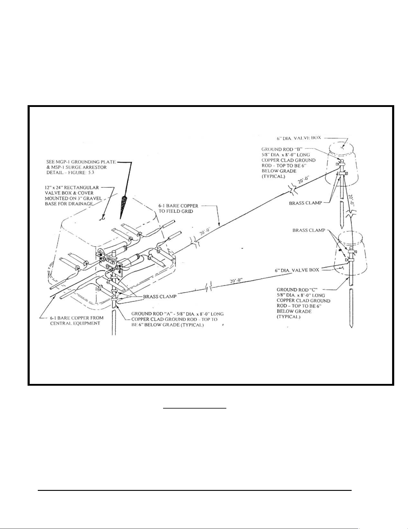
GT27141C Page 62 November 2003
System antenna should also be mounted above the point at which the field wiring or
communication cable will enter the building. In this way the same grounding grid can be used
for grounding of the antenna and the coaxial cable surge arrestor. Orient this opening with the
18” side closest to the building. In the center of this opening, drive a ground rod so that the top
is 6” below the finish grade (this will be ground rod “A” as shown in FIGURE: 4.2).
FIGURE: 4.2
GROUNDING GRID LAYOUT FOR CENTRAL CONTROL EQUIPMENT
GT27141D Page 63 November 2003
Caution !
When working with the #6 (10mm²) or larger ground wire,
take care not to make any sharp bends or kinks in the wire
at any point of its routing as this will increase its
RESISTANCE to ground – thereby decreasing the
effectiveness of your ground grid. All bends shall be long,
smooth radii of as large a radius as possible.
Using a measuring tape, mark a point at least 20’-0” (6 meters) away from the rod you have
driven closest to the building. This is the point at which ground rod “B” shall be driven. From
this ground rod “B”, carefully lay out a 20’-0” (6 meter) equilateral triangle to form the ground
grid. If possible, locate these rods in a wetted area away from nearby trees. It may be
necessary to go further than 20’-0” (6 meter) but that is acceptable. Refer to FIGURE: 4.2
shown above.
PREPARATION OF VALVE BOX – Before installing the valve box in the ground, with a
3/8” bit, pre-drill a single hole in the back center of the valve box, in the side away from the
building and about 8” (200 mm) up from the bottom. Two #6 (10mm²) bare copper ground
wires will be run through this hole to the two ground rods (“B” & “C”), of the field ground grid
(Refer to FIGURE: 4.2 shown above). On the end of the valve box that will be closest to the
building, pre-drill a single 3/8” hole in the center and about 8” (200 mm) up from the bottom.
The bare copper ground wire from the Line Termination Box and/or central equipment will be
run through this hole. If you will have more than one ground wire coming from the central
equipment – drill the number of 3/8” holes that will be required for each of the ground wires, to
each side of the center hole. Place a minimum of 3” (75 mm) of gravel in the bottom of the hole
you have dug for the valve box and set the valve box so that the top is even with the finish grade.
FIELD GROUND GRID INSTALLATION – At the locations for installing ground rods “B”,
& “C”, excavate a 12” (300 mm) diameter hole, about 10” (250 mm) deep. In the center of
each of these holes, drive a 5/8” dia. x 8’-0” long copper clad ground rod so that the top is 6”
(150 mm) below the finish grade. At ground rod “B” & “C”, slide on 2 brass clamps on each
rod. Connect ground rod “B” to ground rod “C” using a piece of #6 (10mm²) or larger bare
copper wire. Connect ground rod “C” to ground rod “A” using a piece of #6 (10mm²) or larger
bare copper wire. Connect ground rod “B” to ground rod “A” using a piece of #6 (10mm²) or
larger bare copper wire. The wires are to be a minimum of 12 inches (300mm) below the finish
grade. Make all wire connections to the rods with a separate brass clamp. DO NOT attempt to
place more than one wire in a given clamp because there is a potential for poor connections,
either at initial installation or over a period of time. Place a 6” diameter valve box over each of
the two ground rods “B”, & “C” to provide access to the clamps for maintenance checking for
tightness and also providing a moist soil environment for better grounding conditions.

GT27141C Page 64 November 2003
INSTALLATION OF MGP-1 AND MSP-1 ASSEMBLY – Each MGP-1 Grounding Plate
Assembly can accommodate two (2) MSP-1 Surge Arrestors. Each Two-Wire communication
path or cable leg coming to the central location from the field decoders, will be spliced to an
MSP-1 Surge Arrestor assembly The MGP-1 Grounding Plate assembly has two (2) threaded
opening for accepting MSP-1 Surge Arrestors. For example, if there are two (2) Two-Wire
paths, then one (1) MGP-1 Grounding Plate assembly and two (2) MSP-1 Surge Arrestors will
be needed (one for each wire path). For three (3) or four (4) Two-Wire paths, two (2) MGP-1
Grounding Plate Assemblies and the corresponding number of MSP-1 Surge Arrestors to match
the number of wire paths that will be needed.
ASSEMBLY OF MGP-1 AND MSP-1 UNITS – The first step is to slide two (2) brass clamps
on to the 5/8” dia. x 8’-0” long copper clad ground rod “A”, that you have previously driven into
the ground. Next mount the MGP-1 Grounding Plate assembly on ground rod “A”, near the top
of the rod, using the two (2) “U-Bolt” clamps and spacers provided. Coat the threads on the
“U-Bolt” clamps with Anti-Seize or other similar compound.
The two ends of the MSP-1 Surge Arrestor are labeled “EQUIP” and “FIELD” respectively.
From each end of the MSP-1 there is a black wire, a red wire and a green (ground) wire. On the
end of the green ground wire, from each end of the MSP-1, crimp a small open end spade lug.
Coat the threads of the MSP-1 on the end labeled “EQUIP” with Anti-Sieze or other similar
compound. Push the three wires, from this end of the MSP-1, through one of the threaded
openings of the MGP-1 Grounding Plate assembly. Firmly screw the MSP-1 into the threaded
opening. Repeat this same procedure for each of the other MSP-1 Surge Arrestors, if there are
more than one Two-Wire path involved with your installation. Coat the threads of all ground
screws on the MGP-1 Grounding Plate assembly with Anti-Seize or other similar compound.
Loosen one of the ground screws on the MGP-1 and slide the spade lugs, from both green
ground wires coming from each end of the MSP-1 Surge Arrestor, under the screw and firmly
tighten. Refer to FIGURE: 4.2 and FIGURE: 4.3 for further details. Repeat this same
procedure for the green ground wires from the other MSP-1 Surge Arrestors that you may have
involved with your system – crimping on the open end spade lugs and firmly connecting them to
one of the ground screws on the MGP-1 Grounding Plate assembly.
CONNECTING TWO-WIRE COMMUNICATION PATHS – The Two-Wire
communication paths coming from the field decoders need to be connected to the MSP-1 Surge
Arrestors that you have mounted in the MGP-1 Grounding Plate assembly.
GT27141D Page 65 November 2003
Caution !
It is very important that you keep track of which incoming leg
of the Two-Wire Communication cable goes to which portion
of the golf course. As you proceed with the central installa-
tion, mark the wire with a permanent marking pen or other
type of permanent marking tag, indicating what area or holes
of the course it is serving.
WIRING OF TWO – WIRE COMMUNICATION PATHS COMING FROM FIELD
DECODERS – Run the incoming legs of the Two-Wire Communication paths, coming from the
decoders in the field, through the large opening in back of
the valve box (the side toward the field). Leave a foot or more of slack in the cables, inside the
valve box, so that connections can be easily brought to grade level for easy inspection and
working on them if required in the future. Each of the individual Two-Wire cables shall be
connected to one of the MSP-1 Surge Arrestors on the end labeled “FIELD”. Connect the RED
wire of the cable to the RED wire of the MSP-1 Surge Arrestor. Connect the BLACK wire of
the cable to the BLACK wire of the MSP-1 Surge Arrestor. Use 3-M DBY or DBR direct
burial splice kits for these connections. Use the splicing techniques as previously described.
Refer to FIGURE: 4.3 as shown below. Repeat this procedure for each of the Two-Wire cables
that you have coming from the field decoders.
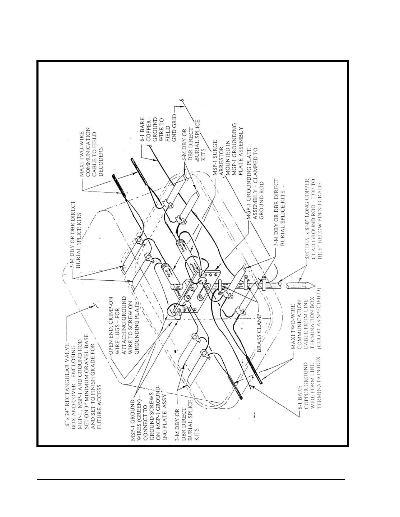
GT27141C Page 66 November 2003
CENTRAL LOCATION – INSTALLATION DETAIL FOR MGP-1
GROUNDING PLATE ASSEMBLY, MSP-1 SURGE ARRESTORS
AND CENTRAL GROUNDING
FIGURE: 4.3
GT27141D Page 67 November 2003
WIRING OF TWO-WIRE COMMUNICATION PATHS COMING FROM THE LINE
TERMINATION BOX AT THE CENTRAL LOCATION - Run
the Two-Wire communication cables coming from the Line Termination Box through the large
opening in the side of the valve box that is closest to the building. Leave a foot or more of slack
in the cables, inside the valve box, so that connections can be easily brought to grade level for
easy inspection and working on them if required in the future. Each Two-Wire cable shall be
connected to one of the MSP-1 Surge Arrestors on the end labeled “EQUIP”. Connect the RED
wire of the cable to the RED wire of the MSP-1 Surge Arrestor. Connect the BLACK wire of
the cable to the BLACK wire of the MSP-1 Surge Arrestor. Use 3-M DBY or DBR direct burial
splice kits for these connections. Use the splicing techniques as previously described. Refer to
FIGURE: 4.3 as shown above. Repeat this procedure for each of the Two-Wire cables that you
have coming from the Line Termination Box.
CONNECTING GROUND WIRES AT CENTRAL LOCATION - Connect a #6 or larger
bare copper ground wire to one of the brass clamps you have placed
on ground rod “A”, at the central equipment location. Run this ground wire through the 3/8”
diameter drilled hole in the back of the valve box (the side toward the field). Extend the wire
over to ground rod “B” and connect it to the rod by using one of the three (3) brass clamps you
have placed on the rod previously. Refer to FIGURE: 4.1 and FIGURE: 4.2. Run a #6 or
larger bare copper ground wire, from the ground terminal lug in the Line Termination Box,
through the 3/8” drilled hole in the end of the box that is toward the building. Connect the
ground wire to ground rod “A” using the other brass clamp you have previously placed on this
rod. Remember not to make any sharp bends or place any kinks in these ground wires as this
will only add resistance to the ground network and reduce the effectiveness of the grounding
system. All bends shall be long smooth radii of as large a radius as possible.
You have now completed the installation of the Surge Protection of the Two-Wire Paths coming
from the field decoders and going to the Line Termination Box. In addition the proper
grounding network has also been accomplished to provide proper effectiveness of the surge
devices.
NOTE ! For detailed installation instructions and drawings for the MDI, LDI,
SDI Interface Units and the Line Termination Box – refer to the ADDENDUM AT
THE END OF THIS MANUAL.
POWER SUPPLY (120 VAC) SURGE PROTECTION – The 120 VAC Power Supply is the
electrical circuit that will be used to supply power for the Central Computer, MDI Interface
Unit, Monitor, Printer, etc. for all the central equipment required. The transformer in the MDI
will supply power to the decoders and solenoids in the field over the two-wire path.
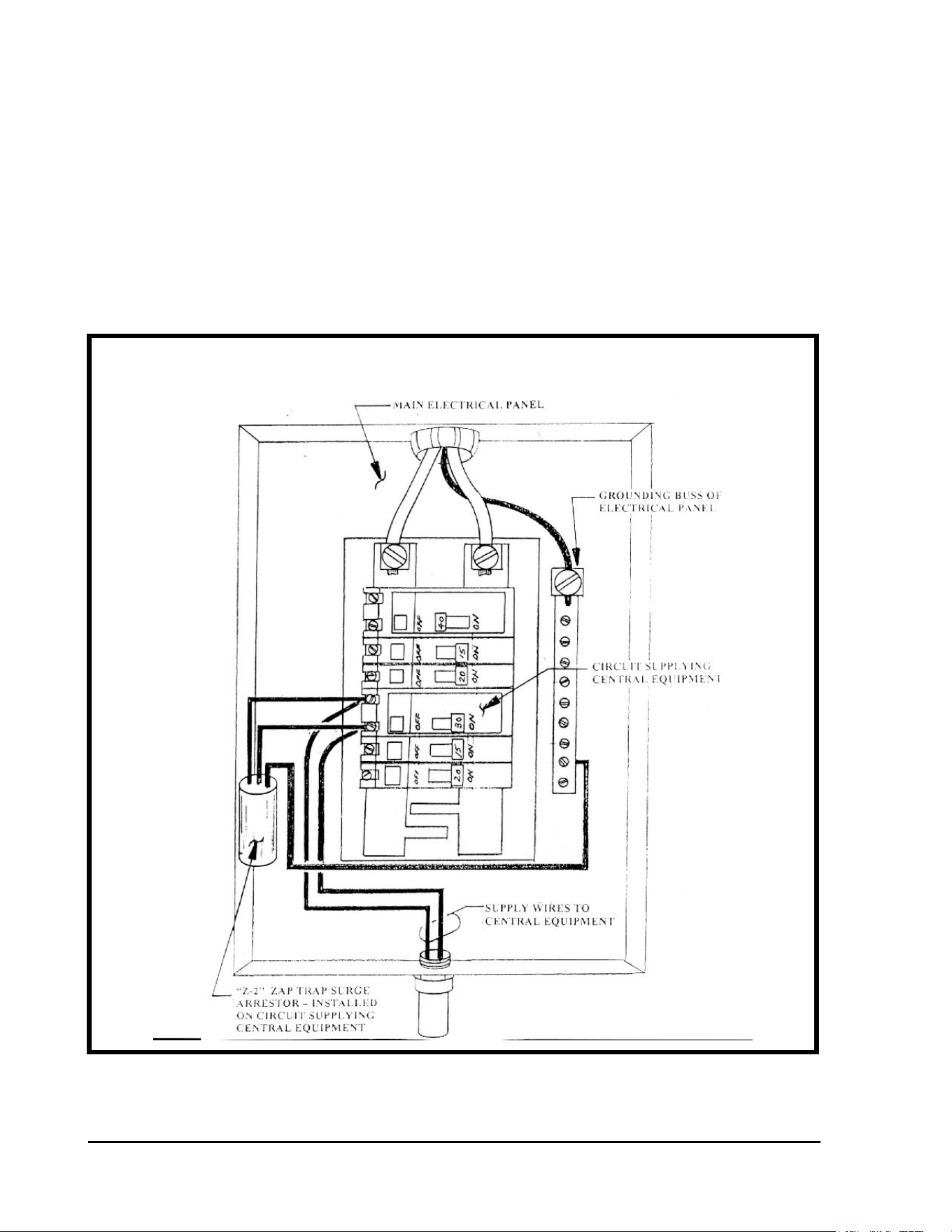
GT27141C Page 68 November 2003
CENTRAL EQUIPMENT SURGE PROTECTION AT MAIN
ELECTRICAL SERVICE PANEL
As shown in FIGURE: 4.4 below, surge protection is provided by wiring into the circuit
supplying the central equipment (at the main electrical panel) a Model Z-2 “ZAP TRAP”
Power Filter surge arrestor, as manufactured by Tytewadd Power Filters, Springfield,
Missouri (417-887-3770).
The “ZAP TRAP” surge arrestor shall be installed in the main electrical panel and wired into the
circuit supplying the 120 VAC Power to the central equipment. The “ZAP TRAP” shall be
grounded to the grounding buss of the main electrical panel. Refer to FIGURE: 4.4 shown
below.
FIGURE: 4.4
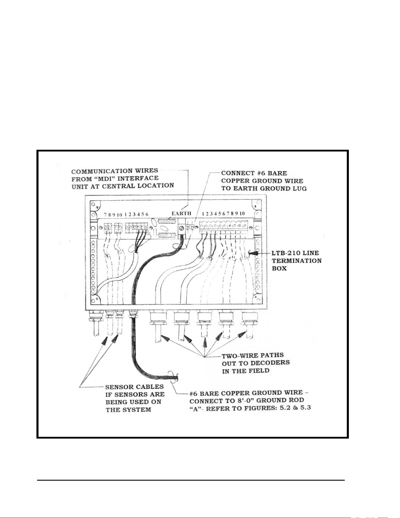
GT27141D Page 69 November 2003
LTB-210 LINE TERMINATION BOX GROUNDING DETAIL
LTB-210 LINE TERMINATION BOX – A Line Termination Box shall be installed at the
central location and as near as possible to the Central grounding grid network as practical, but
not further than 90 feet from the MDI UNIT.. The Line Termination Box has surge protection
devices built into it. From the center GROUND LUG – labeled “EARTH” it is necessary to
install #6 , or larger, bare copper ground wire and run it out and connect it to Ground Rod “A”
of the central grounding grid network. Refer to FIGURE: 4.3 (previously shown) and
FIGURE: 4.5 as shown below. The ground wire shall be as straight and as short as possible.
Avoid any sharp “bends” or “kinks” in the wire as these will only cause additional resistance to
the network.
FIGURE: 4.5

GT27141C Page 70 November 2003
Chapter
5
LSP-1
Surge Protection and Proper Grounding of
the Field Decoders, Solenoids and Com-
munication Wire Paths
Proper Surge Protection and Proper Grounding of the Field Decoders, Solenoids
and the Two-Wire Communication Paths is the Key to the Long and Trouble Free
Operation of your System and the Minimal Loss of Decoders and Solenoids due to
Lightning Surges on the System.
PRIMARY SURGE PROTECTION FOR THE FIELD DECODERS
AND THE FIELD SOLENOIDS ARE LSP-1 SURGE ARRESTORS -
The LSP-1 Surge Arrestor, consists of several surge arrestor devices “potted” in a cylindrical
plastic case ( the same case as is used for the
FD-102 and the FD-202 except the case color is YELLOW rather than BLACK as used for the
decoders.
The LSP-1 surge arrestor has two (2) BLUE wires, which connect into the
Two-Wire communication path at the decoder location. Polarity is not
important so either blue wire may be connected – one to the BLACK wire of
the Two-Wire path and the other to the RED wire of the Two-Wire path. There are also two (2)
GROUND wires (Green in color), with the ground wire having the “closed eye” spade, to be
securely connected to the core tube of the solenoid, on the Valve-in-Head rotor or on the
Remote Control valve by means of a stainless steel nut threaded onto the core tube. The other
ground wire shall be connected to a driven 5/8” Dia. x 8’-0” long copper clad ground rod, using
a brass clamp to do so. Refer to FIGURES: 5.1 thru 5.7 shown below.
GT27141D Page 71 November 2003
NOTE !
A minimum of 50 OHMS or less is required for the ground resistance to assure the LSP-1 surge
arrestor being effective. In most installations it will require at least an 8’-0” long ground rod to
obtain 50 OHMS or less resistance. In some instances it may take three (3) 8’-0” rods in a
triangular pattern, tied together below grade with #10 AWG or larger bare copper ground wire,
to obtain 50 OHMS or less resistance. It is absolutely necessary to obtain and maintain a
ground resistance of 50 OHMS or less if the LSP-1 Surge Arrestor is to be effective.
EXCEPTION – In those situations, where the decoder IS NOT located next to t he
solenoid, the LSP-1 surge arrestor shall be located at the decoder and the two (2) green
GROUND wires shall both be connected to the 5/8” Dia. x 8’-0’ copper clad ground rod, or one
of the rods in the 3-rod ground grid, if it is required to get 50 OHMS or less resistance, and each
attached by a separate brass clamp. DO NOT ATTACH BOTH WIRES IN THE SAME
BRASS CLAMP ! It is difficult to get the two wires to tightly secure to the rod, by using one
clamp, and also the two wires are much more prone to come loose when using one clamp for the
two wires. Thus the effectiveness of the ground is greatly diminished or perhaps lost altogether
– thus no protection provided. Although it may be necessary to make the installation in this
manner in some instances – it IS NOT THE PREFERRED method of installation nor the most
effective method of installation. Therefore, when at all possible this method should not be used
but rather the method, where the core tube of the solenoid is also grounded, should be used.
As mentioned above, wherever possible the decoder, for controlling a
given valve-in-head rotor, as well as, for controlling the remote solenoid
control valve for a battery system of sprinklers, shall be installed immediately adjacent to the
solenoid actuator. In this way the LSP-1 Surge Arrestor, with its grounding system can be such
as to ground the solenoid core tube as well as the surge arrestor itself. THIS IS THE
MOST EFFECTIVE SURGE PROTECTION for the Decoders and the Solenoids.
SURGE PROTECTION OF FIELD DECODERS AND TWO-WIRE
COMMUNICATION PATHS – Proper location of field decoder Surge Arrestors (LSP-1) and
proper grounding of these devices can assure you of a reasonable amount of protection against
damage from lightning strikes. Since each decoder system installation will be different, it is not
possible to give specific detailed requirements for each. However, if some care is exercised and
the following general guide lines are followed a reasonably protected system can be achieved.
GT27141C Page 72 November 2003
LSP-1 LOCATIONS
GUIDE LINES FOR LOCATION AND INSTALLATION OF LSP-1 SURGE
ARRESTORS – Although each layout will be different, the following should act as a guide in
determining or estimating the number of LSP-1 surge arrestors required on your system.
• 9-HOLE Golf Course: Approximately 20 to 30 LSP-1’s.
• 18-HOLE Golf Course: Approximately 40 to 60 LSP-1’s.
• At a Dead End: Whenever the two-wire path terminates in a “Dead End” - an LSP-1
Surge Arrestor shall be installed at the last decoder before the “Dead End”. If the
“Dead End” is designed with an FD-401 or FD-601 decoder as the last decoder before
the “Dead End”, which contains a built-in LSP-1 surge arrestor as an integral part of
the decoder, this decoder and its built-in LSP-1 surge arrestor will be sufficient to
provide adequate surge protection.
• Along the Wire Path in a Block Installation: Install an LSP-1 Surge Arrestor so
that there are no more than eight (8) decoders between two (2) LSP-1 surge arrestors
or there is no more than 500 feet between the LSP-1’s, which ever is less, according
to the installation guidelines given above. Refer to FIGURE: 5.1 shown below.
• Along the Wire Path in a VIH Installation: Install an LSP-1 Surge Arrestor, so
that there are no more than eight (8) decoders between two (2) LSP-1 surge arrestors
or there is no more than 500 feet between LSP-1’s, which ever is less, according to
the installation guidelines given above. Refer to FIGURE: 5.2 shown below..
INSTALLATION OF LSP-1 SURGE ARRESTORS: As outlined above, LSP-
1 Surge Arrestors are installed along the Two-Wire communication path and also at “Dead Ends”
of the Two-Wire path.
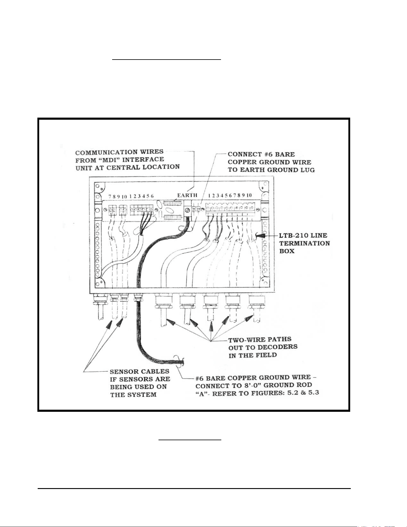
GT27141D Page 73 November 2003
LSP-1 SURGE ARRESTOR INSTALLED ALONG
TWO-WIRE PATH AT AN FD-210/FD-102 DECODER
LSP-1 installed along the Two-Wire path at an FD-102 Decoder
LSP-1 Surge Arrestors shall be installed along the Two-Wire path as shown on the drawings and
as required for adequate protection of the Decoders and Solenoids. Those LSP-1 Surge
Arrestors that are being installed with an FD-102 Decoder shall be installed as shown in
FIGURE: 5.1 below.
FIGURE: 5.1
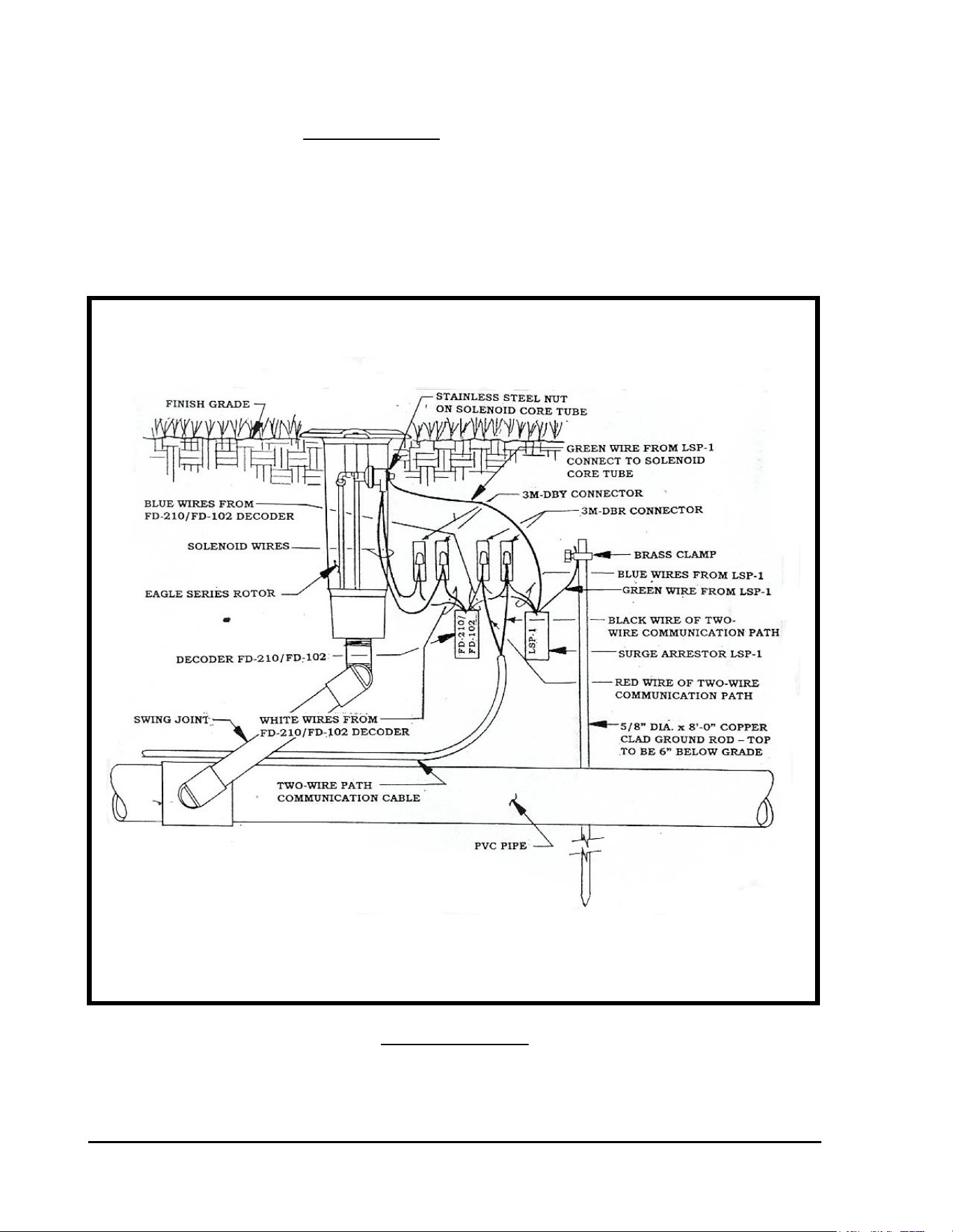
GT27141C Page 74 November 2003
LSP-1 installed at a “Dead End” of the Two-Wire path at an FD-102
Decoder.
An LSP-1 Surge Arrestors shall be installed at a “Dead End” of the Two-Wire path as shown on
the drawings and as required for adequate protection of the Decoders and Solenoids. Those
LSP-1 Surge Arrestors that are being installed with an FD-102 Decoder shall be installed as
shown in FIGURE: 5.2 below.
FIGURE: 5.2
LSP-1 SURGE ARRESTOR INSTALLED AT A “DEAD END” OF
THE TWO-WIRE PATH AT AN FD-102 DECODER
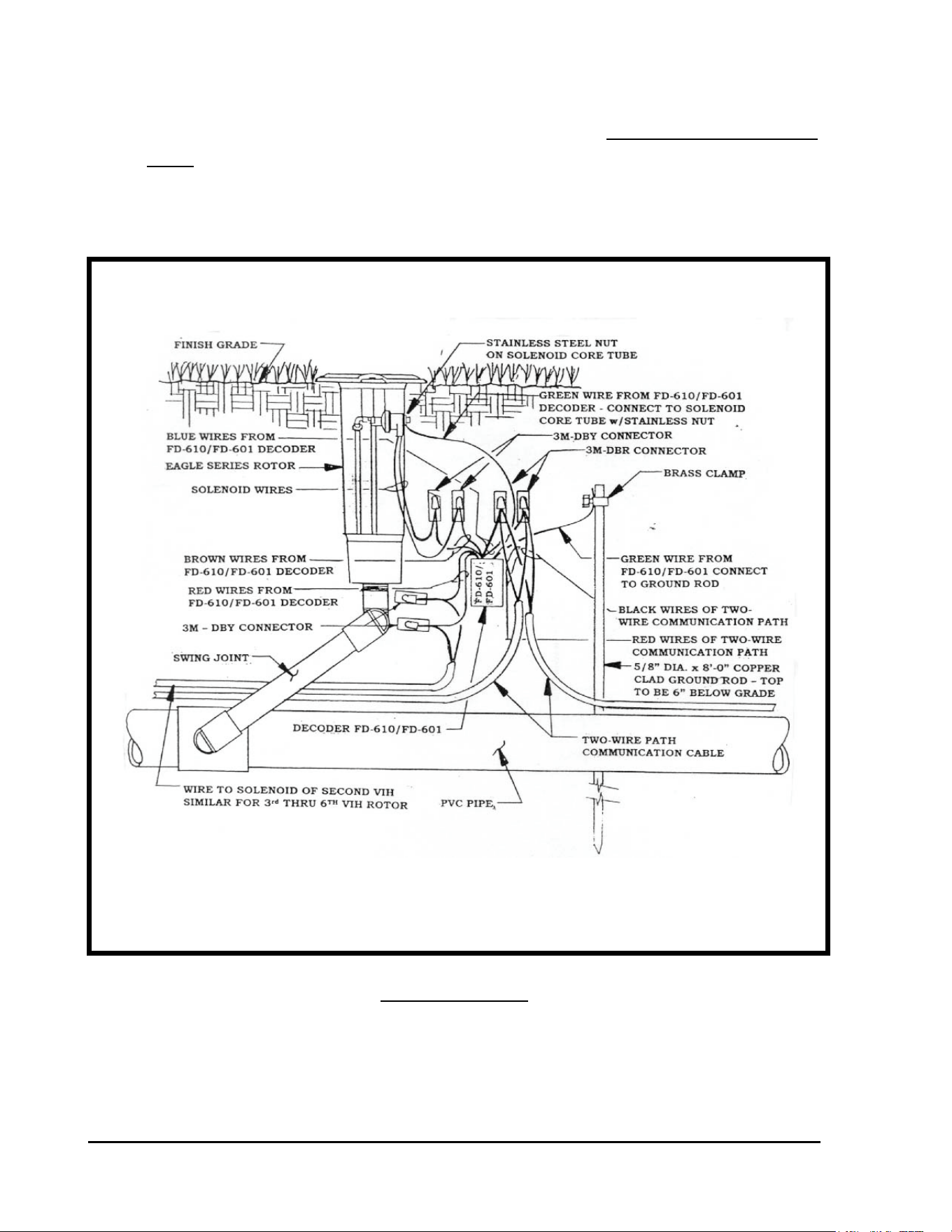
GT27141D Page 75 November 2003
FD-601 DECODER INSTALLATION DETAIL WHEN INSTALLED
ALONG THE TWO-WIRE PATH
LSP-1 “built-in” an FD-601 Decoder installed along the Two-Wire
path. (FD-401 is similar)
The FD-601 Decoders have a “built-in” LSP-1 surge arrestor. Those FD-601 Decoders along
the Two-Wire path shall be installed as shown in FIGURE: 5.5 below.
FIGURE: 5.5
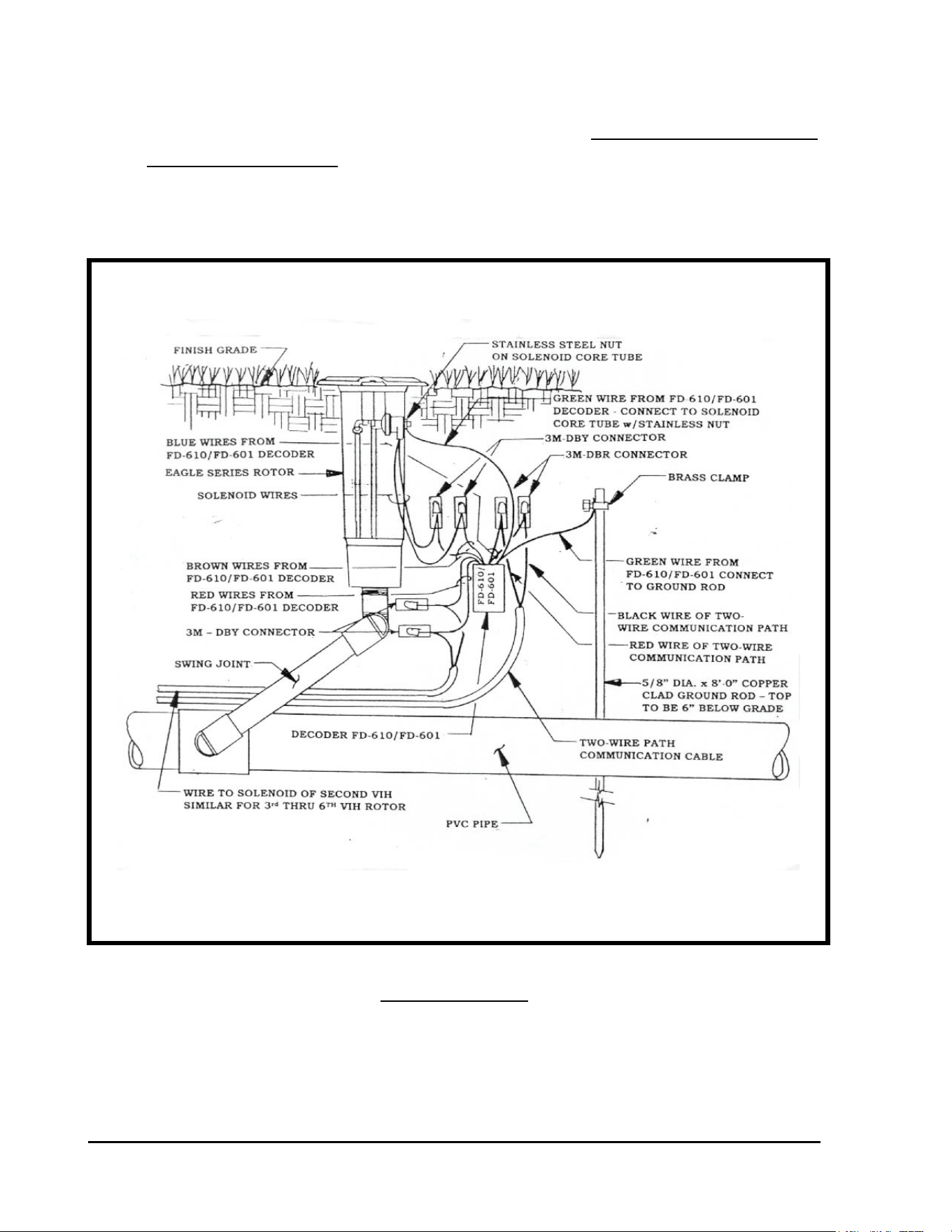
GT27141C Page 76 November 2003
FD-601 DECODER INSTALLATION DETAIL WHEN
INSTALLED AT THE “DEAD END” OF THE TWO-WIRE PATH
LSP-1 “built-in” an FD-601 Decoder installed at the “Dead End” of
the Two-Wire path. (FD-401 is similar).
The FD-601 Decoders have a “built-in” LSP-1 surge arrestor. Those FD-601 Decoders located
at thte “Dead End” of the Two-Wire path shall be installed as shown in FIGURE: 5.6 below.
FIGURE: 5.6
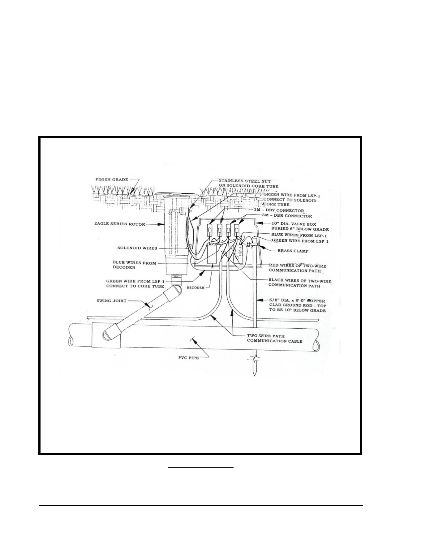
GT27141D Page 77 November 2003
TYPICAL INSTALLATION DETAIL FOR ALL LSP-1
SURGE ARRESTORS TO BE PLACED IN A VALVE BOX
RECORD LOCATION OF ALL LSP-1 SURGE ARRESTORS – It is
extremely important to note on the “as-built” plans the location of all LSP-1 Surge Arrestors as
this can greatly assist in future troubleshooting of the system. It is strongly recommended to
place the decoder and the LSP-1 surge arrestor in a 10” diameter valve box, which is buried
6” below grade and next to the valve-in-head sprinkler or remote control valve.
Refer to FIGURE: 5.7 shown below. This will provide easy and quick access to the decoder
and LSP-1 surge arrestor, when troubleshooting the system.
FIGURE: 5.7
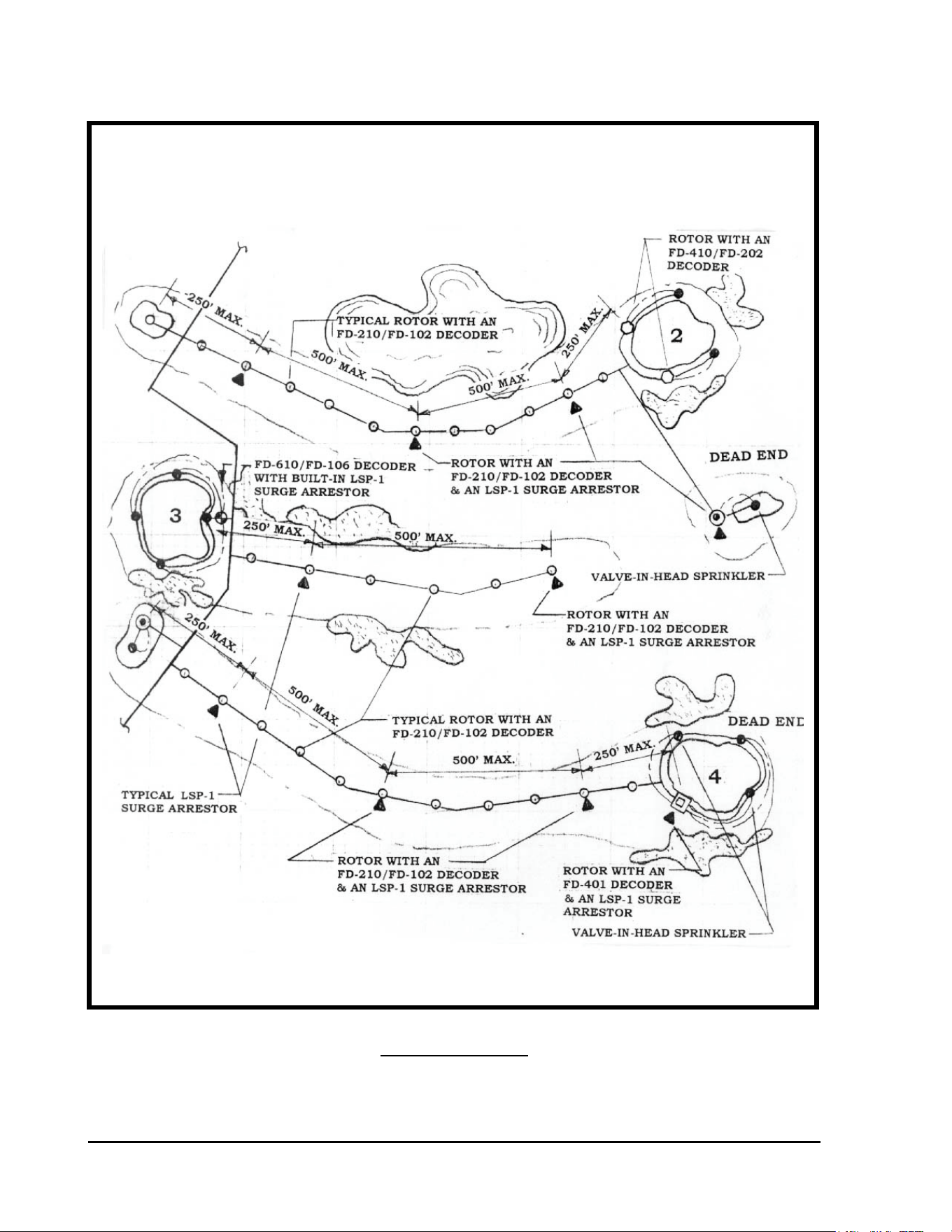
GT27141C Page 78 November 2003
FIGURE: 5.8
GUIDE FOR LOCATING LSP-1 SURGE ARRESTORS ON A
SINGLE ROW, DECODER OPERATED, VALVE-IN-HEAD
SYSTEM
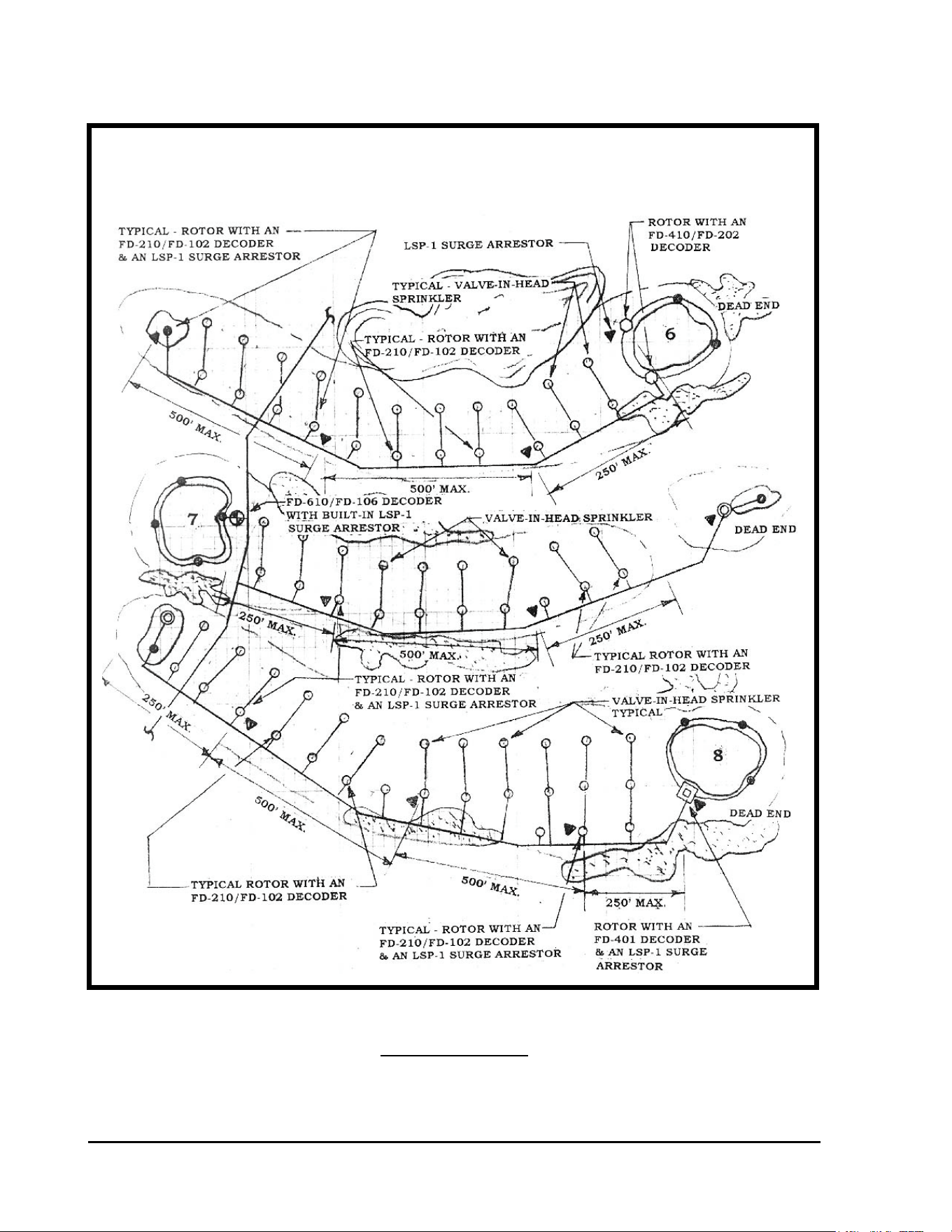
GT27141D Page 79 November 2003
FIGURE: 5.9
GUIDE FOR LOCATING LSP-1 SURGE ARRESTORS ON A
TYPICAL BLOCK, DECODER OPERATED, VALVE-IN-HEAD
OR REMOTE CONTROL VALVE SYSTEM
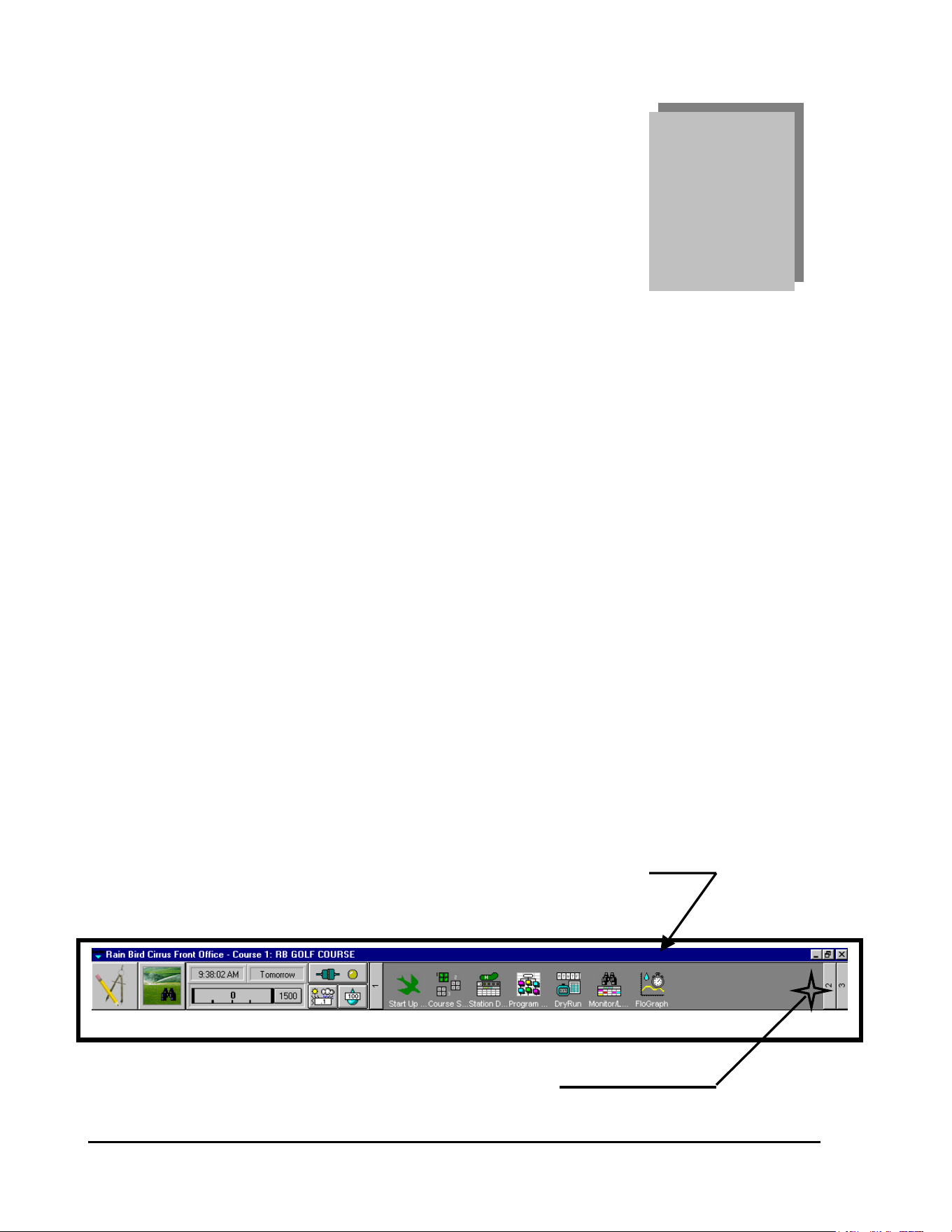
GT27141C Page 80 November 2003
Chapter
6
Programming the
Decoder System
The Following Programming Instructions Pertain to the Following Rain Bird
Decoder Control Systems:
Stratus & Stratus II
Nimbus & Nimbus II
Cirrus
The following programming procedure illustrates the necessary steps required to
program the Decoder System, and is based on the Cirrus Control System. The other Stratus
and Nimbus Control Systems program in a similar manner.
Configuring the Decoder System:
The first thing you must do is “Configure” the Decoder System.
STEP #1: “FRONT OFFICE” SCREEN HEADER
Start from the “Front Office” screen of the software.
CLICK ON THE “ITEM 2” ICON
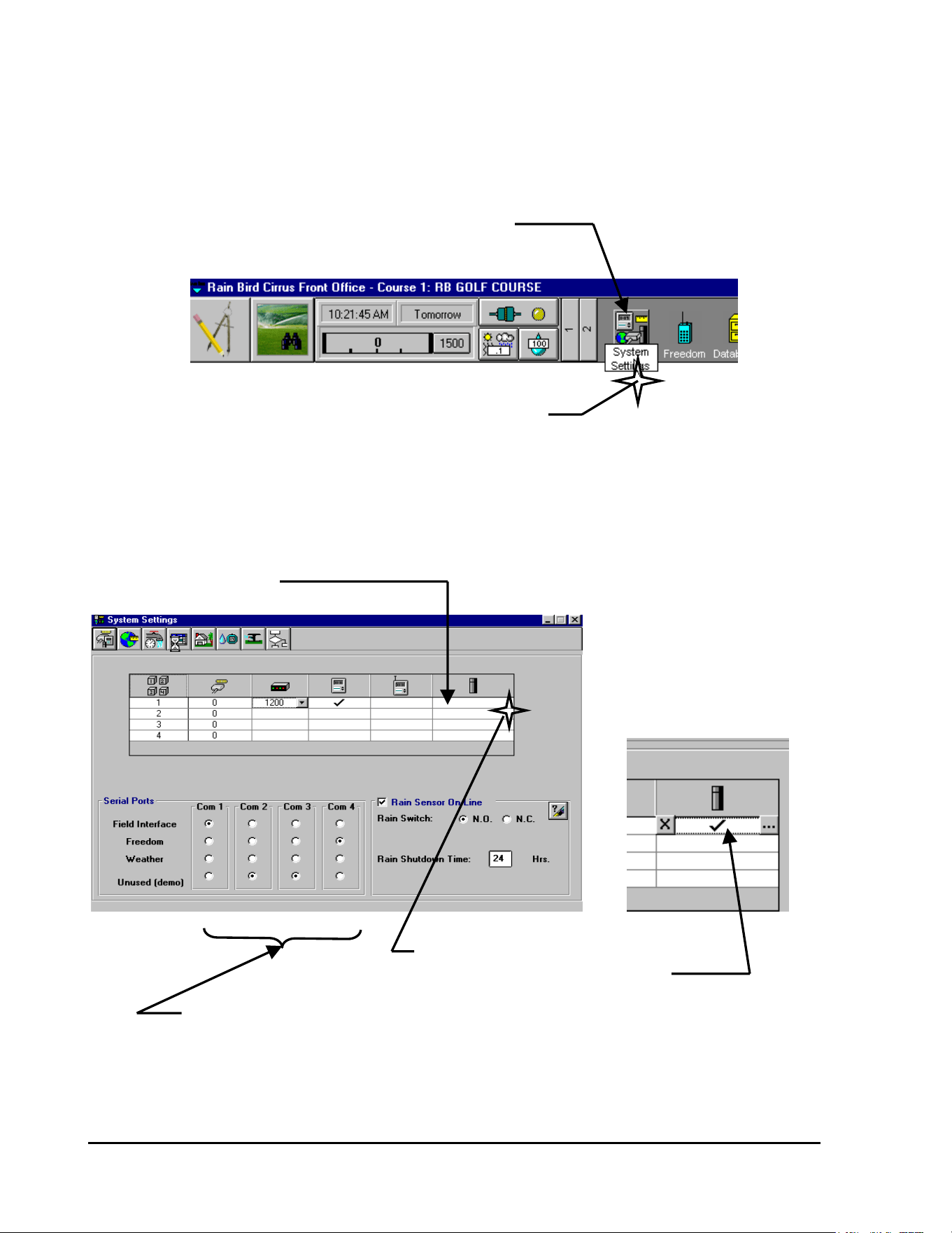
GT27141D Page 81 November 2003
The following screen, showing additional Icons on the Front Office Header, will now be
displayed.
SYSTEM CONFIGURATION ICON
CLICK ON THE “SYSTEM CONFIGURATION” ICON
The following “System Settings” screen will be displayed . . .
STEP #2:
Since we are configuring a “Decoder” system – CLICK on the Decoder Cell.
DECODER CELL
CLICK ON “DECODER” CELL
TO DESIGNATE THE SYSTEM
IS TO BE A DECODER SYSTEM
SYSTEM “COM” PORT DESIGNATIONS
STEP #3:
Designate the use for each of the various COM Ports of your computer.
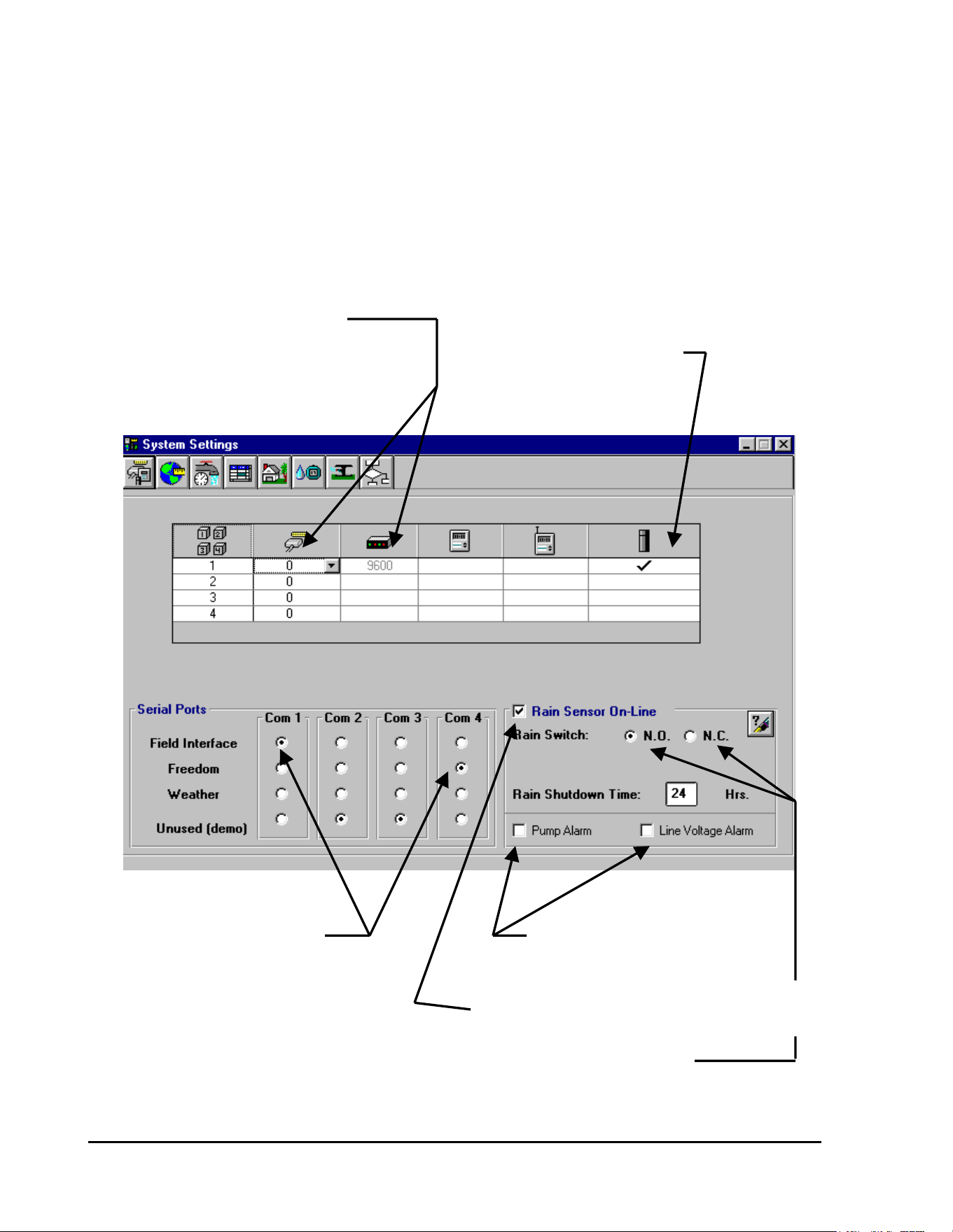
GT27141C Page 82 November 2003
STEP #4:
Designate if you have a Rain Sensor on your system and whether its thresold condition is
“Normally Open” (N.O.) or “Normally Closed” (N.C.). Indicate the duration of the Rain Shut-
Down period desired. Also designate – if you have a Pump Alarm and/or a Line Voltage Alarm
on your system.
Your “System Settings” screen should now appear similar to the screen displayed below . . .
THIS DATA IS AUTOMATICALLY
ENTERED WHEN YOU DESIGNATE
THE SYSTEM TO BE A DECODER SYSTEM DESIGNATED TO
TYPE SYSTEM BE A DECODER SYSTEM
“COM” PORT DESIGNATIONS CLICK HERE IF YOU HAVE A
PUMP ALARM OR A LINE
VOLTAGE ALARM
CLICK HERE IF YOU HAVE A RAIN SENSOR
ON YOUR SYSTEM & WANT IT “ON-LINE”
DESIGNATE IF THE SENSOR THRESHOLD
CONDITION IS “NORMALLY OPEN” (N.O.) OR
“NORMALLY CLOSED” (N.C.) BY “CLICKING”
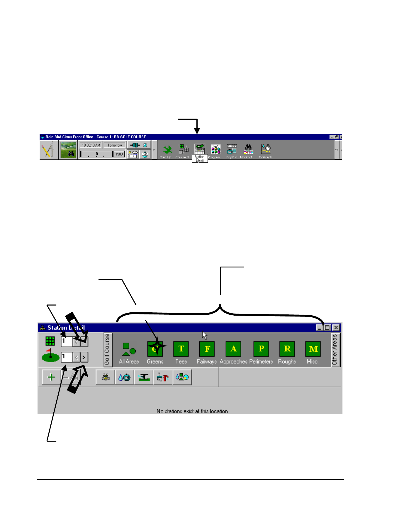
GT27141D Page 83 November 2003
ON THE CORRECT CONDITION
Entering Decoder Data:
STEP #1:
From the FRONT OFFICE screen – SELECT “Station Detail” as shown below . . .
CLICK ON “STATION DETAIL” ICON
The “Station Detail” screen, as shown below, will be displayed . . .
STEP #2:
The screen automatically shows Course Number 1 and Hole Number 1 as being selected to
program. If this is not the Course or the Hole you wish to program – then select the proper
Course Number and Hole Number you want to program.
AREAS THAT MAY
BE PROGRAMMED
CLICK ON “G” for
GREENS
COURSE NUMBER
HOLE NUMBER
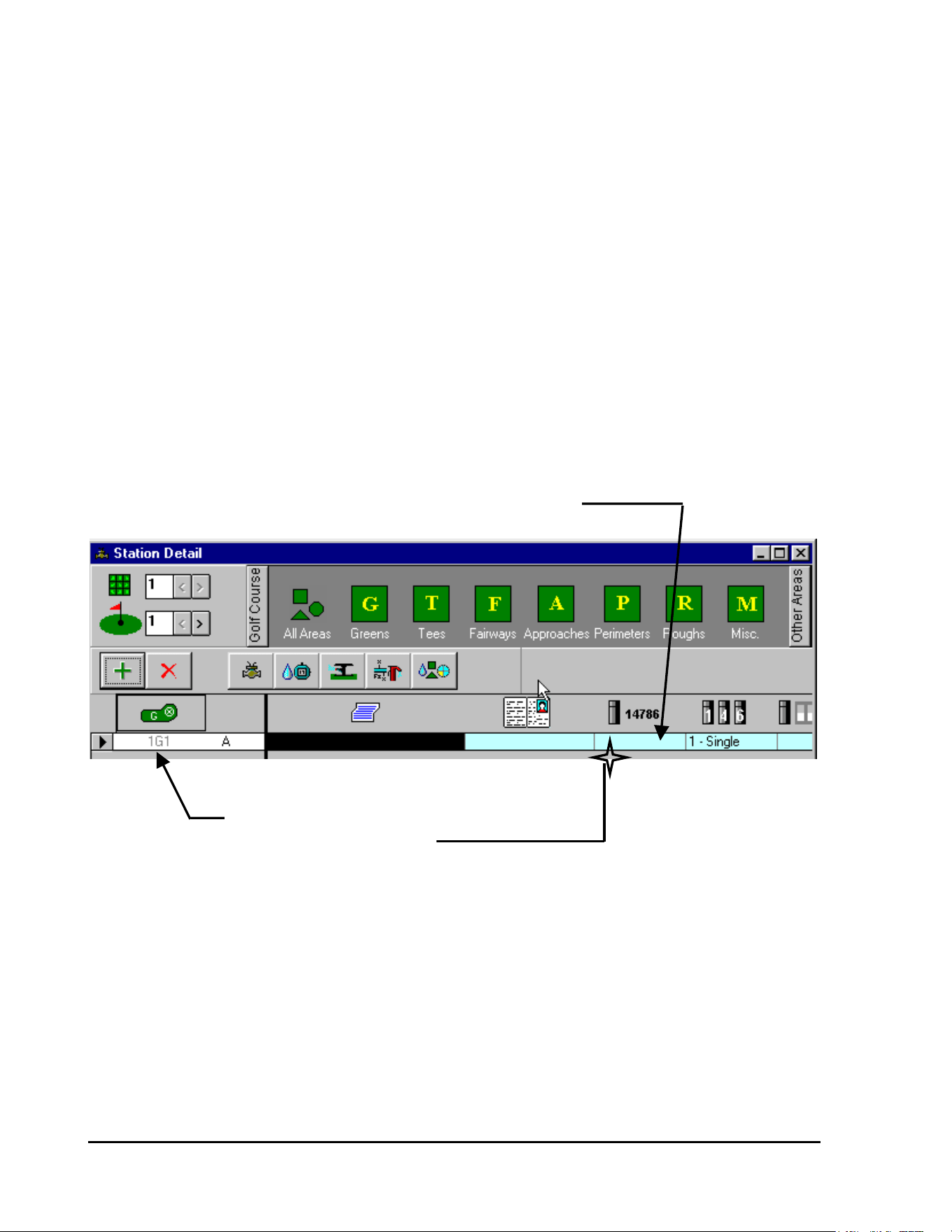
GT27141C Page 84 November 2003
STEP #3:
Select the Area that you wish to program.
Having selected the proper Course Number and Hole Number – then CLICK on the AREA you
wish to program – in this example we want to program the GREENS. Clicking on the GREENS
Icon the following screen will be diaplayed . . .
Screen is displayed showing “1G1” as the first Decoder to be identified in this table.
STEP #4:
Enter the Decoder Identification Code Number for location “1G1”
ENTER THE DECODER IDENTIFICATION CODE NUMBER
DECODER FIELD LOCATION
CLICK ON DECODER CODE NUMBER CELL
After CLICKING on the cell – ENTER the Decoder Code Number. In this example use Code
Number 1150.
The Code Number will be shown in the Decoder Identification Code Number CELL – as shown
below…
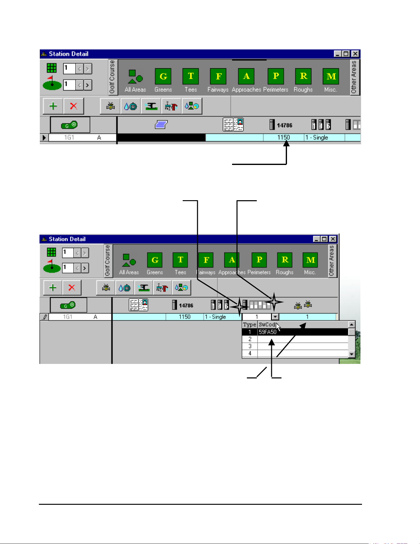
GT27141D Page 85 November 2003
DECODER CODE NUMBER
STEP #5:
DECODER CODE NUMBER
In addition to entering the Decoder Code Number – you also need to designate if the decoder is a
single output (default status), four output or six output type decoder.
DESIGNATE TYPE OF DECODER CLICK ON CELL AND THEN
BY CLICKING ON CELL AND CLICK ON ARROW TO GET
SELECTING PROPER TYPE DROP-DOWN SCREEN
STEP #6: NUMBER OF SOLENOIDS ON DECODER OUTPUT ENTER NEW SWITCH
CODE IF REQUIRED -
Default Switch Code (#1) is automatically entered. Enter a different CLICK ON CELL AND
Switch Code if required for type of solenoid you have. ENTER NEW CODE
STEP #7:
Default Number of solenoids, being operated by decoder output is ONE (1). Change if required.
The other data in this table will be automatically entered in accordance with the data you have
entered for the various “System Data Tables”. Adjustments may be made on an individual
station basis as may be required.
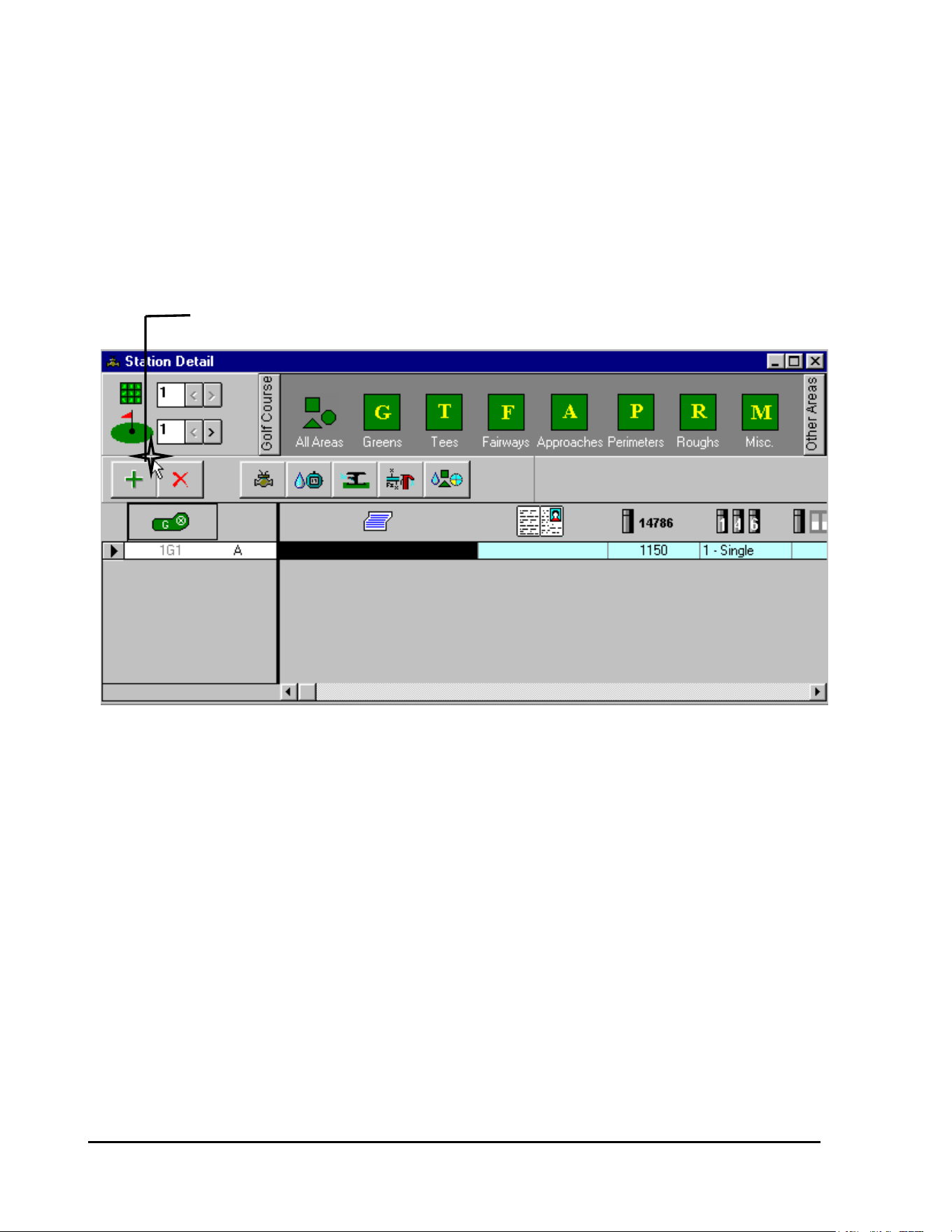
GT27141C Page 86 November 2003
STEP #8:
Enter, in a similar manner, the data for each of the other decoders that you may have for this
selected area (Green #1 – in this case).
To advance to the next station – CLICK on the PLUS (+) Icon.
CLICK ON THE “+” ICON
Station 1G2 will now be displayed – and you can enter the proper data for it. Repeat this for
each of the other decoders that you have for this area.
When you have finished entering the data for all the decoders at this Green – your table should
appear similar to the screen shown below . . .
(REFER TO NEXT PAGE FOR SCREEN)
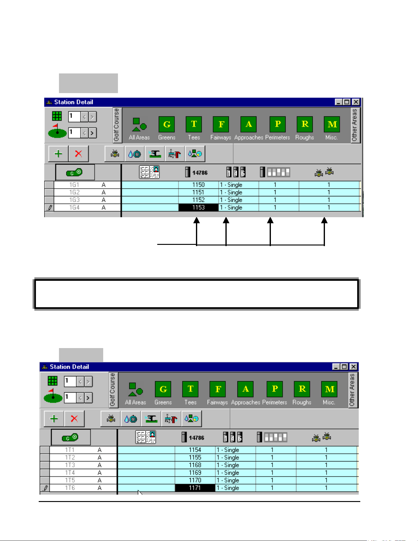
GT27141D Page 87 November 2003
GREEN #1
SCREEN SHOWS DECODER CODE
NUMBERS AND DATA FOR ALL
FOUR DECODERS AT GREEN #1
Repeat Steps #1 through #8, as shown above, for entry of all Decoder data
for all the other areas of your system.
When you have finished entering all decoder data for each hole you should have screens similar
to these shown below for each hole of your system.
TEE #1
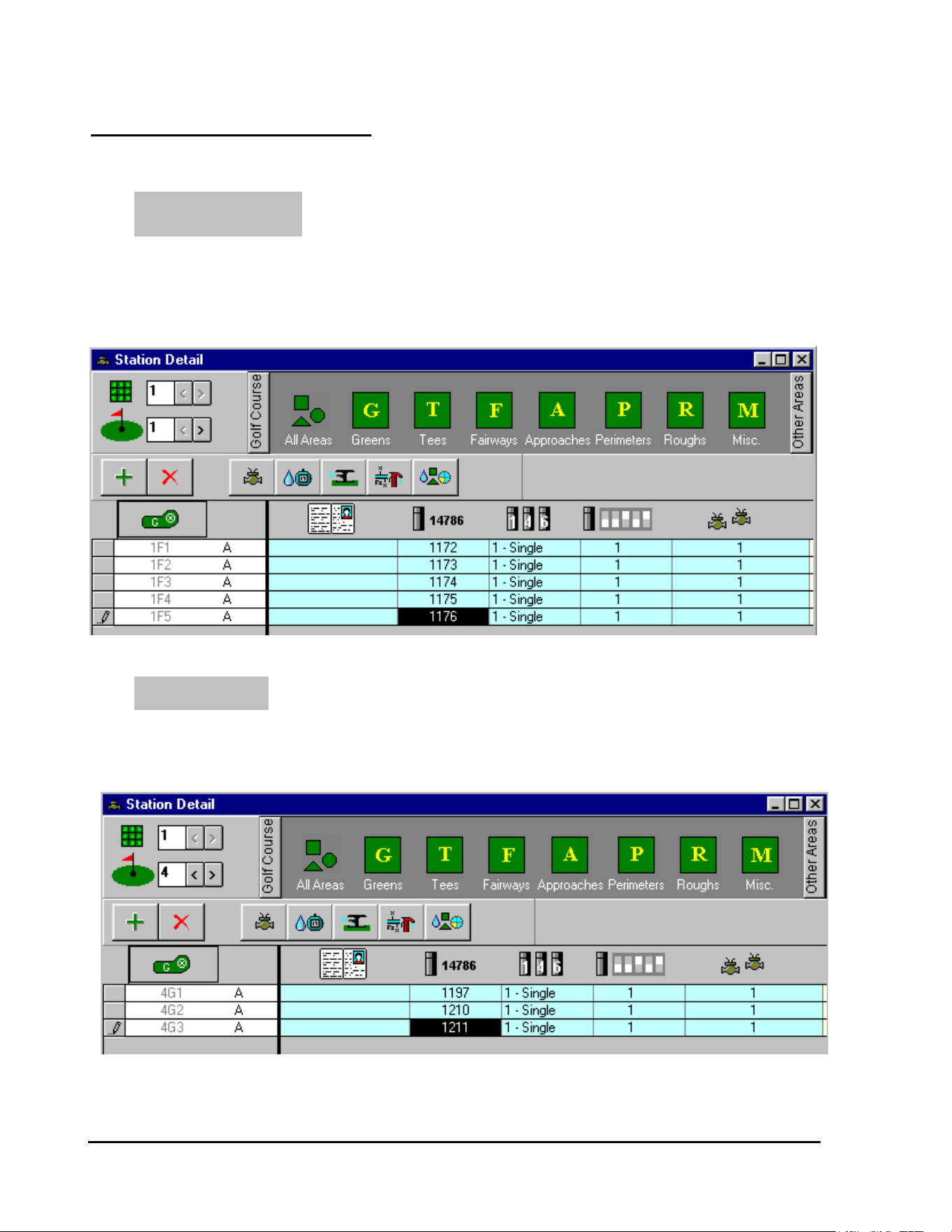
GT27141C Page 88 November 2003
OTHER SAMPLE SCREENS
FAIRWAY #1
GREEN #4
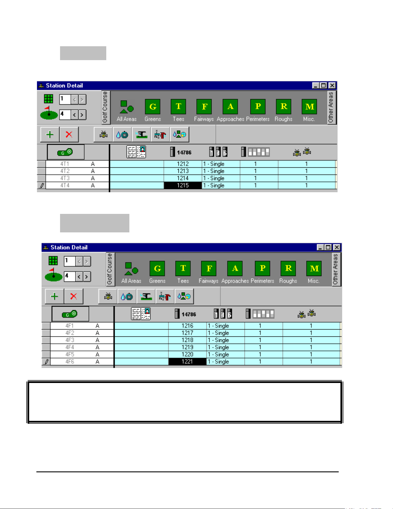
GT27141D Page 89 November 2003
OTHER SCREENS FOR YOUR SYSTEM WOULD BE SIMILAR. YOUR
SYSTEM SHOULD NOW BE PROGRAMMED FOR OPERATION AS A
DECODER TYPE SYSTEM.
TEE #4
FAIRWAY #4
GT27141C Page 90 November 2003
Decoder “Switch Code”:
The Decoder “Switch Code” is necessary to assure that the proper Electrical
Characteristics (current, voltage and time) are delivered to the Decoder for operation of the
Valve-in-Head or Remote control valve solenoid.
Magnetic Solenoids on Valve-in-Head rotors or on remote control valves operate with a complex
voltage in order to save energy. The voltage varies with the time as shown in the FIGURE 6.1
below.
In the beginning the voltage must be “HIGH” (Va) in order to make the mechanical parts move.
When the valve has opened or the relay has activated (in the case of a pump decoder), it is
normally possible to lower the voltage (Vh) and still keep the solenoid or relay in the activated
condition.
Time 1 (100ms)
Va (31)
Factory Set Valuse are Shown in ( ).
Volts
Time 2 (Infinite)
Vh (2.3)
Time
Activating Voltage for Solenoid or Relay
FIGURE: 6.1
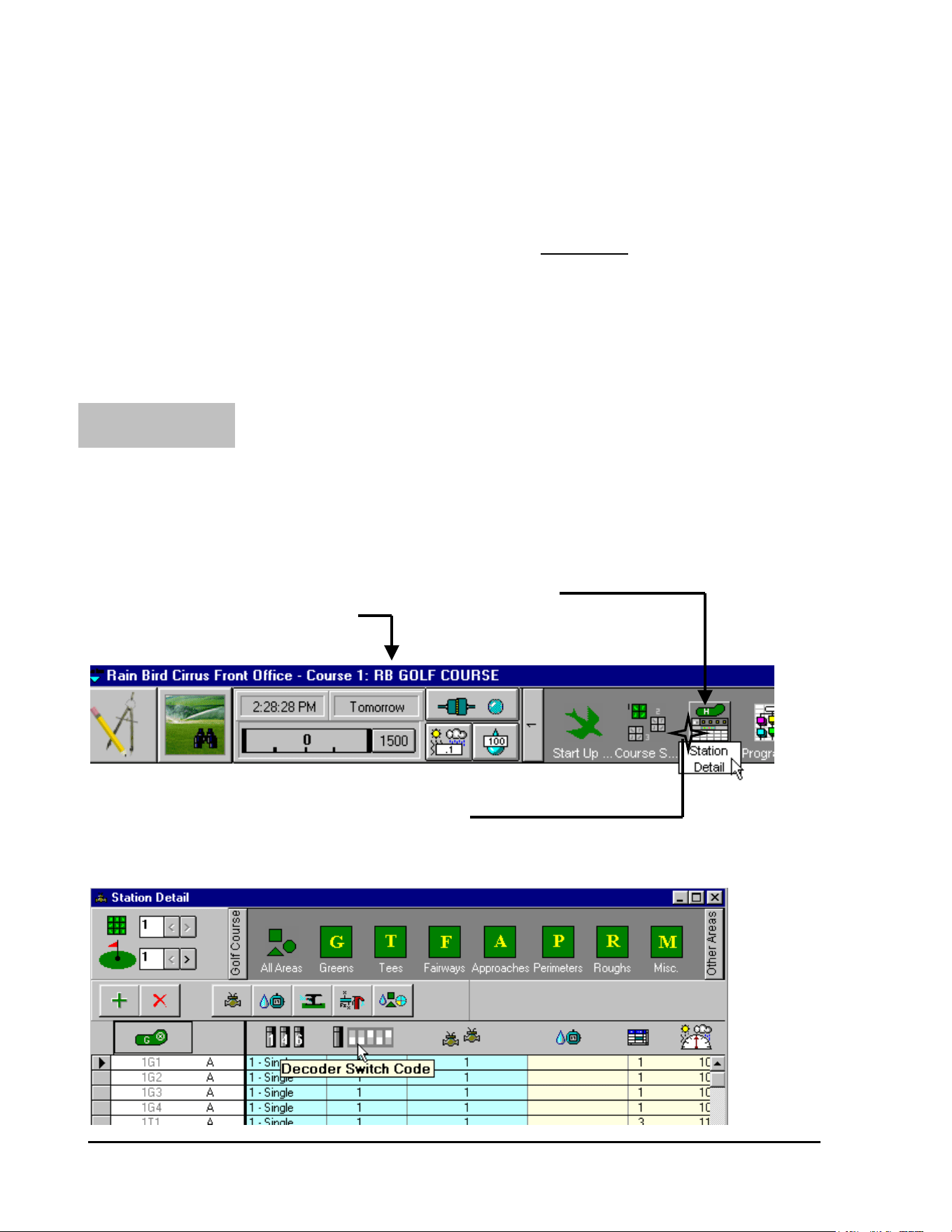
GT27141D Page 91 November 2003
AREA #1:
Standard “Switch Code” for
Rain Bird Solenoids: (Standard = 59FA50)
The Rain Bird Solenoid uses a Standard “Switch Code” of 59FA50. This assures that the
“Initial” voltage of 31 volts is present for the proper amount of time of 100ms – to make sure the
solenoid activates properly and secondly to facilitate the proper “feed back” from the decoder
back to the central computer.
The “Switch Code” for each Decoder can be entered in either one of TWO places in the
software.
The “Switch Code” can be entered on the “Station Detail” tables as you enter the Decoder
Identification Code Number.
From the software “Front Office” tool bar – CLICK on the “Station Detail” ICON.
STATION DETAIL ICON
FRONT OFFICE TOOL BAR
CLICK ON THE “STATION DETAIL” ICON
The “Station Detail” screen will now be displayed as shown below.
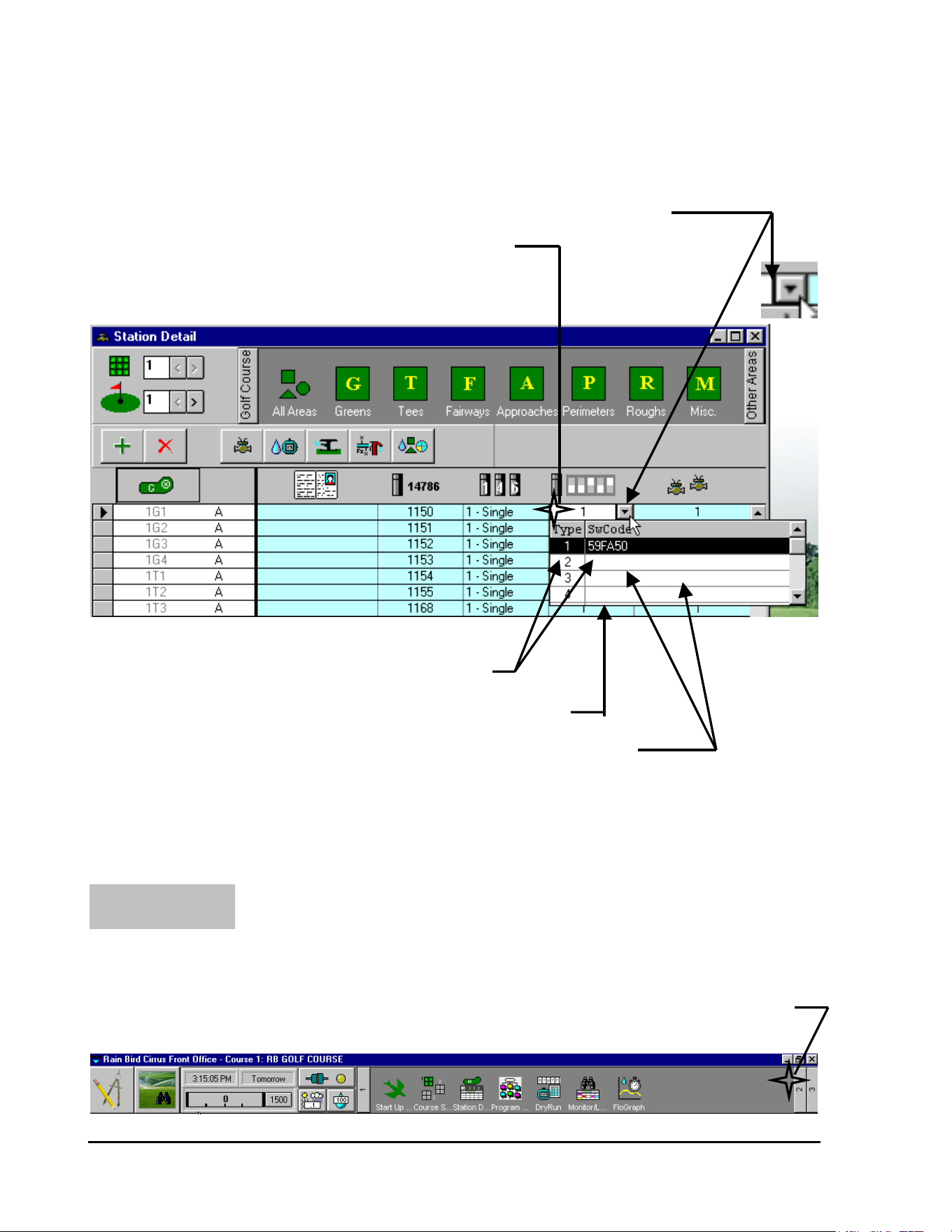
GT27141C Page 92 November 2003
It will be noted in the “Station Detail” screen above that the Decoder “Switch Code”, for each
decoder is automatically entered as “1”, which is for the STANDARD Swith Code of 59FA50.
This can be seen from the screen that is displayed below
2
nd
CLICK ON THE “ARROW” TO GET THE “DROP-DOWN” SCREEN
1
st
CLICK ON THE CELL FOR DECODER SWITCH CODE
TYPE “1” IS THE STANDARD SWITCH CODE
”DROP-DOWN” SCREEN
OTHER “SWITCH CODES” MAY BE ENTERED IN THESE CELLS
Other “Switch Codes” that may be required, can be entered at this – the “Station Detail” screen -
as you enter the Decoder Identification Code Number and other data for it.
The Decoder “Switch Code” can also be entered at the “System Configuration” Screen as you set
up your system for Decoder operation. From the “Front Office” Tool Bar – Click on Item 2.
AREA #2:
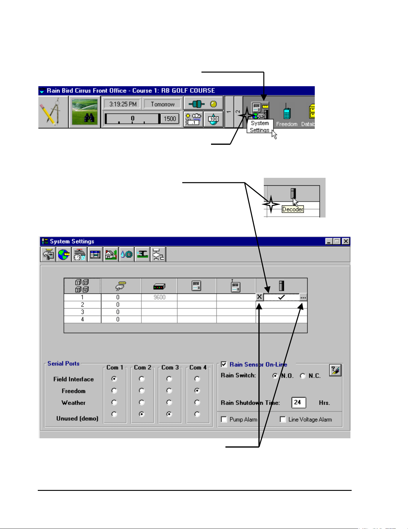
GT27141D Page 93 November 2003
This will give you the second part of the Front Office Tool Bar – as shown below.
“SYSTEM SETTINGS” ICON
CLICK ON THE “SYSTEM SETTINGS” ICON
CLICK on the “System Settings” ICON and the screen will be displayed as shown below.
CLICK ON THE “DECODER” CELL
THIS WILL DISPLAY THE TWO SMALL ICONs AS SHOWN
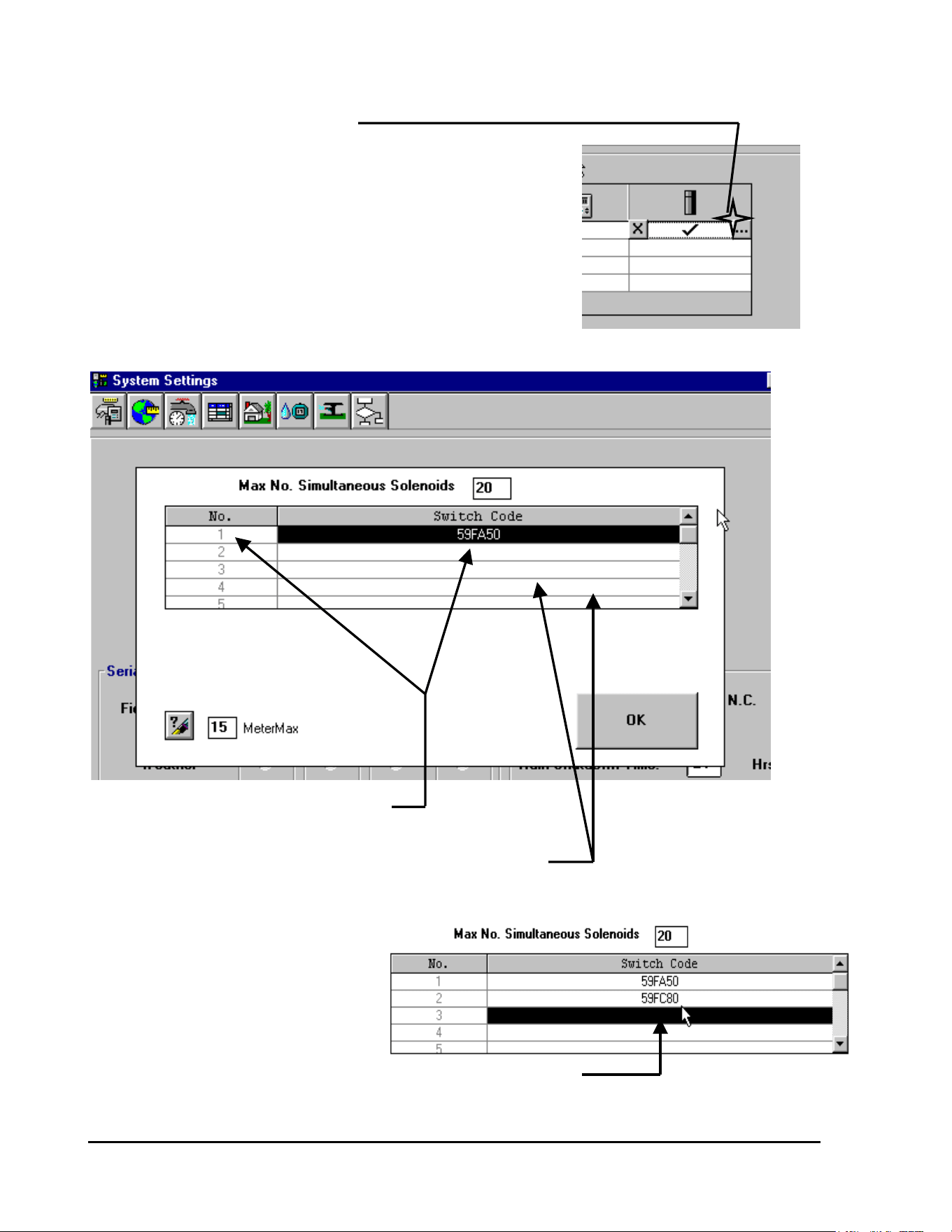
GT27141C Page 94 November 2003
CLICK on the Right small ICON
This will display the “drop-down” screen as shown below.
TYPE 1 IS SHOWN AS THE STANDARD
“SWITCH CODE” OF 59FA50
OTHER “SWITCH CODES” THAT MAY BE REQUIRED
CAN BE ENTERED INTO THESE CELLS
Assume we need to enter a different
special “Switch Code” of 59FC80.
CLICK on the Type 2 cell and enter
the special “Switch Code” as shown .
NEW “SWITCH CODE” FOR TYPE 2 HAS BEEN ENTERED
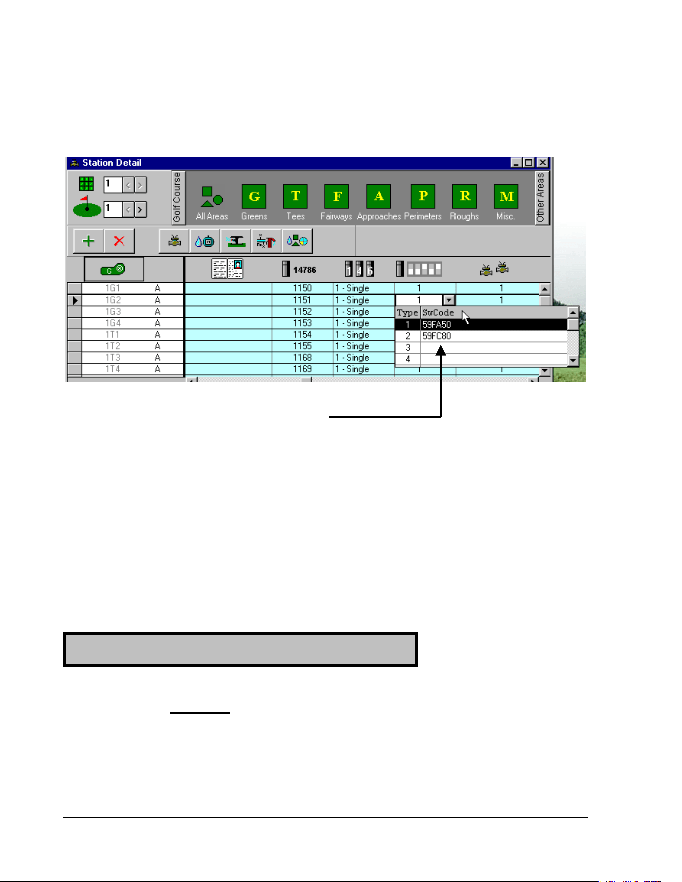
GT27141D Page 95 November 2003
If you check back to the “Station Detail” screen you will see that this TYPE 2 special “Switch
Code” has been automatically entered at this screen also.
SPECIAL “SWITCH CODE” FOR TYPE 2
HAS BEEN AUTOMATICALLY ENTERED
HERE
Asjusting the Electrical Requirement Decoder
“SWITCHING CODE” for Varying Types
of Solenoids:
When the valve or relay DOES NOT work with the Standard “Switching Code” (59FA50) –
there are two properties that you may need to vary.
If the solenoid will NOT open, the activation time (TIME 1) should be prolonged because the
activation voltage (Va) is already set to the MAXIMUM (Va = 31 – set at the factory).
Therefore, change the FOURTH (4
th
) DIGIT of the code according to FIGURE 6.2 – which is
shown below.
If the Solenoid Does Not Open
(
Activate
)
at all:
GT27141C Page 96 November 2003
Electrical Required CODE of Magnetic Solenoid
59F 0
Time ms * * Vh/Volt
30 331.2
40 441.7
50 552.3
60 662.9
70 773.5
80 884.0
90 994.6
100 A A 5.2
110 B B 5.8
120 C C 6.3
130 D D 6.9
140 E E 7.5
150 F F 8.1
TABLE for SELECTING SUITABLE ELECTRICAL
CODE for SPECIAL SOLENOID (VALVE) TYPE.
FIGURE: 6.2
NOTE ! You will have to use the trial and error method until you
get a value that works the solenoid satisfactorily.
Example: Activation Time = 110 ms
Holding Voltage = 2.3 volts
CODE to try = 4
th
Digit = B for 110 milli-seconds
∴ CODE = 59FB50
This increases the “Activation Time” from the standard 100ms to 110ms. You can try this code
and if it still does not operate satisfactorily then make further adjustments to the “Activation
Time” until you get satisfactory operation.
GT27141D Page 97 November 2003
If the solenoid activates but will not stay activated or “ON” (Valve closes back down), the
holding voltage (Vh) is too low and should be increased. Change the FIFTH (5
th
) DIGIT of
the Code according to FIGURE: 6.2 shown above.
NOTE ! Again you will have to use the trial and error method until you
get a value that works the solenoid satisfactorily.
Example: Activation Time = 100 ms
Holding Voltage = 4.0 volts
CODE to try = 5
th
Digit = 8 for 4.0 volts
∴ CODE = 59FA80
This increases the “Holding Voltage” from the standard 2.3 volts to 4.0 volts. You can try this
code and if it still does not operate satisfactorily then make further adjustments to the “Holding
Voltage” until you get satisfactory operation.
You can have as many different “TYPES” or special “Switch Codes” as you may require
for your system. Each special Code that you need can be entered into the software as
previously described above.
Setting Up “Pump Decoder” (Model PD-210)
Operation in the System Software:
For this Example we will use FOUR (4) Pumps and thus use FOUR (4)
PUMP DECODERS for Control of the Pumps for the system.
NOTE ! A Decoder System may have a MAXIMUM of SIX (6) Model PD-210 Pump
Decoders (Pumps).
If the Solenoid Opens (Activates) but
does NOT Stay Open:
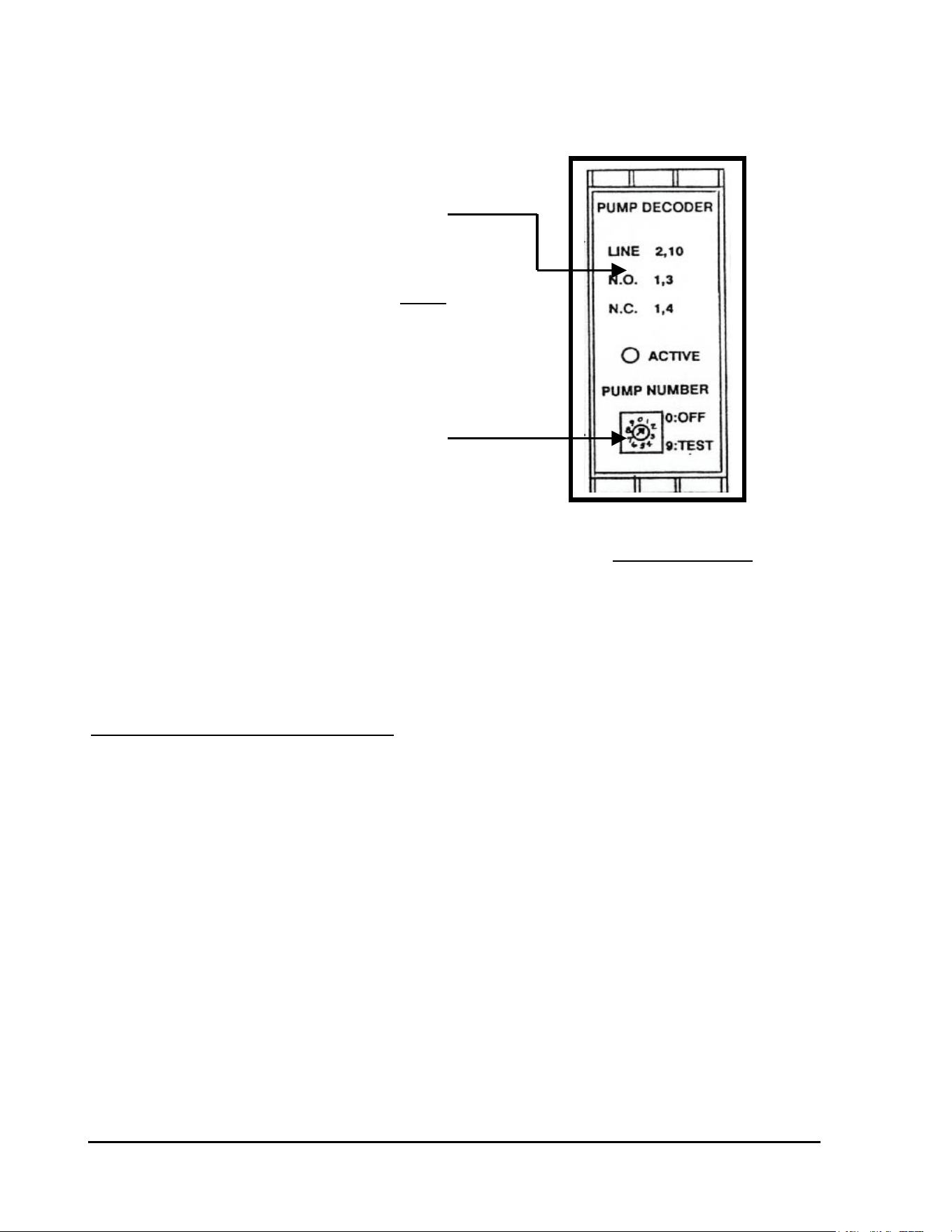
GT27141C Page 98 November 2003
PD-210 DECODER FACE
The Model PD-210 Pump Decoder has a DIAL on
the face of it, which is used to set the Decoder
Address Code Number for it. Refer to the Decoder
Face shown in FIGURE: 6.3 at the right
ADDRESS CODE SETTING DIAL
.
The Numbers on the DIAL automatically give
the Adddress Code Numbers as follows: PUMP DECODER FACE
FIGURE: 6.3
#0 = OFF #9 = TEST
#1 = 284 #2 = 286
#3 = 287 #4 = 292
#5 = 293 #6 = 295
Pump Station Data (for our example:)
Pump #1 = 150 GPM Pump Decoder Dial set at #1, which automacitally
sets the Address Code Number of 284.
Pump #2 = 350 GPM Pump Decoder Dial set at #2, which automatically
sets the Address Code Number of 286.
Pump #3 = 500 GPM Pump Decoder Dial set at #3, which automatically
Sets the Address Code Number of 287.
Pump #4 = 500 GPM Pump Decoder Dial set at #4, which automatically
sets the Address Code Number of 292.
TOTAL PUMP STATION CAPACITY = 1500 GPM
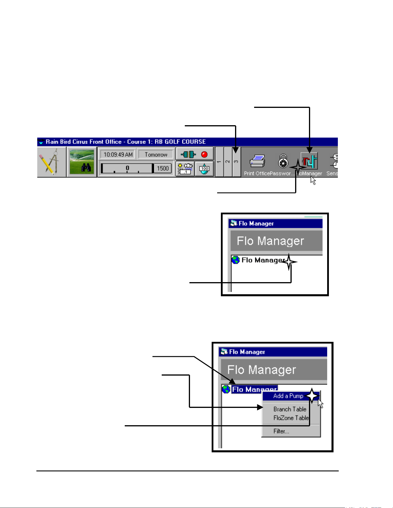
GT27141D Page 99 November 2003
Entering Decoder System Pumping Station
Data into the System Software:
Starting from the Front Office Tool Bar (Section 3) – CLICK on the “Flo Manager” ICON, as
shown below.
“FLO MANAGER” ICON
SECTION #3 OF TOOL BAR BEING DISPLAYED
CLICK ON “FLO MANAGER” ICON
The “Flo Manager” screen will now be
displayed as shown at the right.
CLICK ON “FLO MANAGER” TO HIGHLIGHT IT
With “Flo Manager” now highlighted – CLICK the “RIGHT” mouse button to have the “drop-
down” screen displayed.
“FLO MANAGER” IS HIGHLIGHTED
“DROP-DOWN” SCREEN IS DISPLAYED
BY “CLICKING” RIGHT MOUSE BUTTON
CLICK ON “ADD A PUMP”
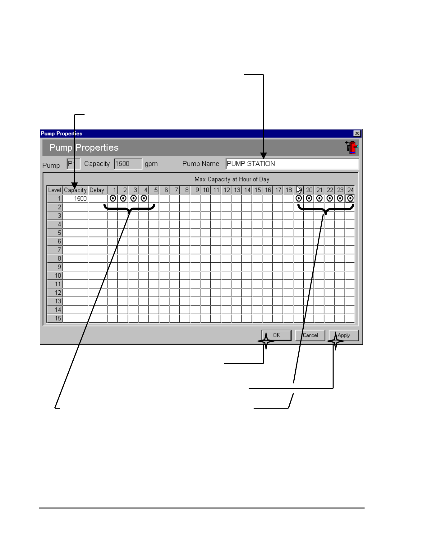
GT27141C Page 100 November 2003
Upon clicking on “Add a Pump” the “PUMP PROPERTIES” screen will be displayed , as
shown below.
ENTER A NAME IF YOU WISH
CLICKING ON THE CELL AND
ENTERING THE NAME
ENTER THE TOTAL CAPACITY OF THE SYSTEM
AFTER CLICKING ON “APPLY”
THEN CLICK ON “OK”
WHEN ALL DATA IS CORRECT
THEN CLICK ON “APPLY”
DESIGNATE THE HOURS OF THE DAY THAT YOU WILL
ALLOW FULL PUMPING STATION CAPACITY – BY
“CLICKING” ON THE DESIRED HOUR CELL
Enter the following data in the chart:
Pump Name (if desired)
Total System Capacity (GPM)
Hours of the Day that you will allow full system capacity to flow
Then Click on “Apply” and followed by clicking on “OK” to permenently enter data.
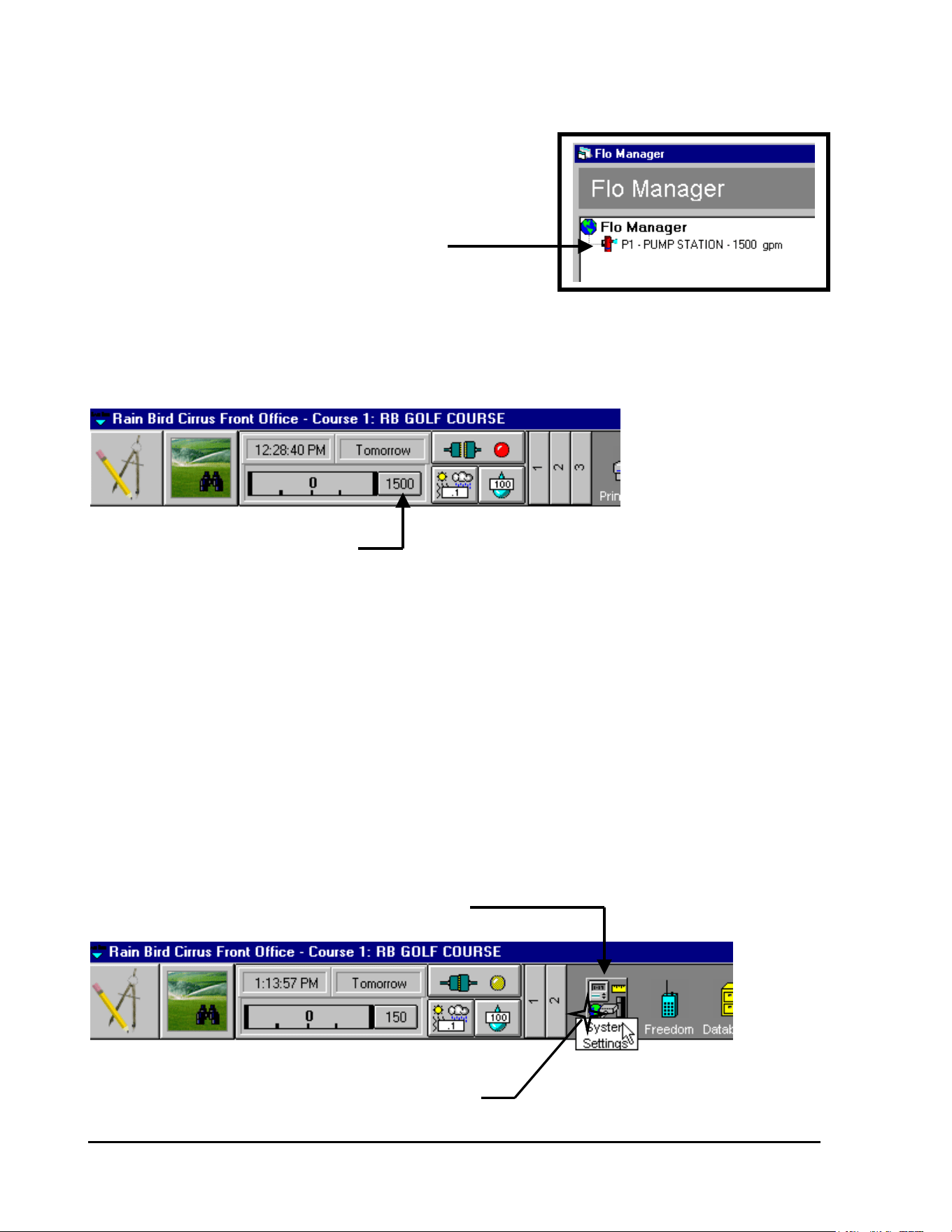
GT27141D Page 101 November 2003
Pump Data will now have been entered into
the “Flo Manager” screen, as shown at
the right.
PUMP “P1” AT 1500 GPM HAS BEEN ENTERED
INTO THE “FLO MANAGER” SCREEN
If you check the “FRONT OFFICE” TOOL BAR – you see that the TOTAL system Capacity is
also displayed here.
TOTAL SYSTEM CAPACITY (GPM)
IS AUTOMATICALLY DISPLAYED HERE
Entering Individual Pump Data, for
System Pumping Station, into the
System Software:
Starting from the “FRONT OFFICE” TOOL BAR (Section 2) – CLICK on the “System
Settings” ICON, as shown below.
“SYSTEM SETTINGS” ICON
CLICK ON THE “SYSTEM SETTINGS” ICON
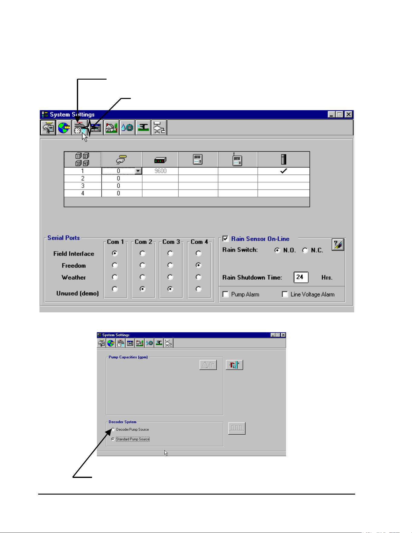
GT27141C Page 102 November 2003
The “System Settings” screen will then be displayed as shown below. CLICK on the “System
Capacities” ICON as shown.
“SYSTEM CAPACITIES” ICON
CLICK ON THE “SYSTEM CAPACITIES” ICON
Upon CLICKING on the “System Capacities” ICON the following screen will then be diaplayed.
CLICK ON THE “DECODER PUMP SOURCE” - FOR OUR DECODER SYSTEM
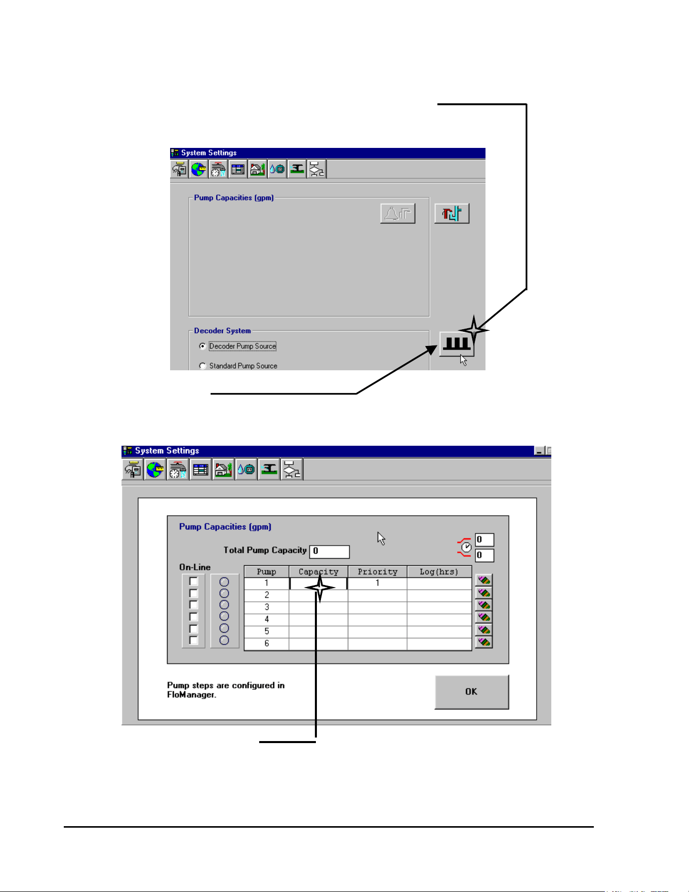
GT27141D Page 103 November 2003
The screen will now be displayed as shown below.
CLICK ON THE DECODER
PUMPS ICON – TO SET UP
PUMP DECODER DATA
DECODER PUMPS ICON
IS NOW DISPLAYED
Upon CLICKING on the “Decoder Pumps” ICON – the following screen will now be displayed.
CLICK ON THE “CAPACITY” CELL
FOR PUMP #1 AND ENTER THE
PUMP CAPACITY
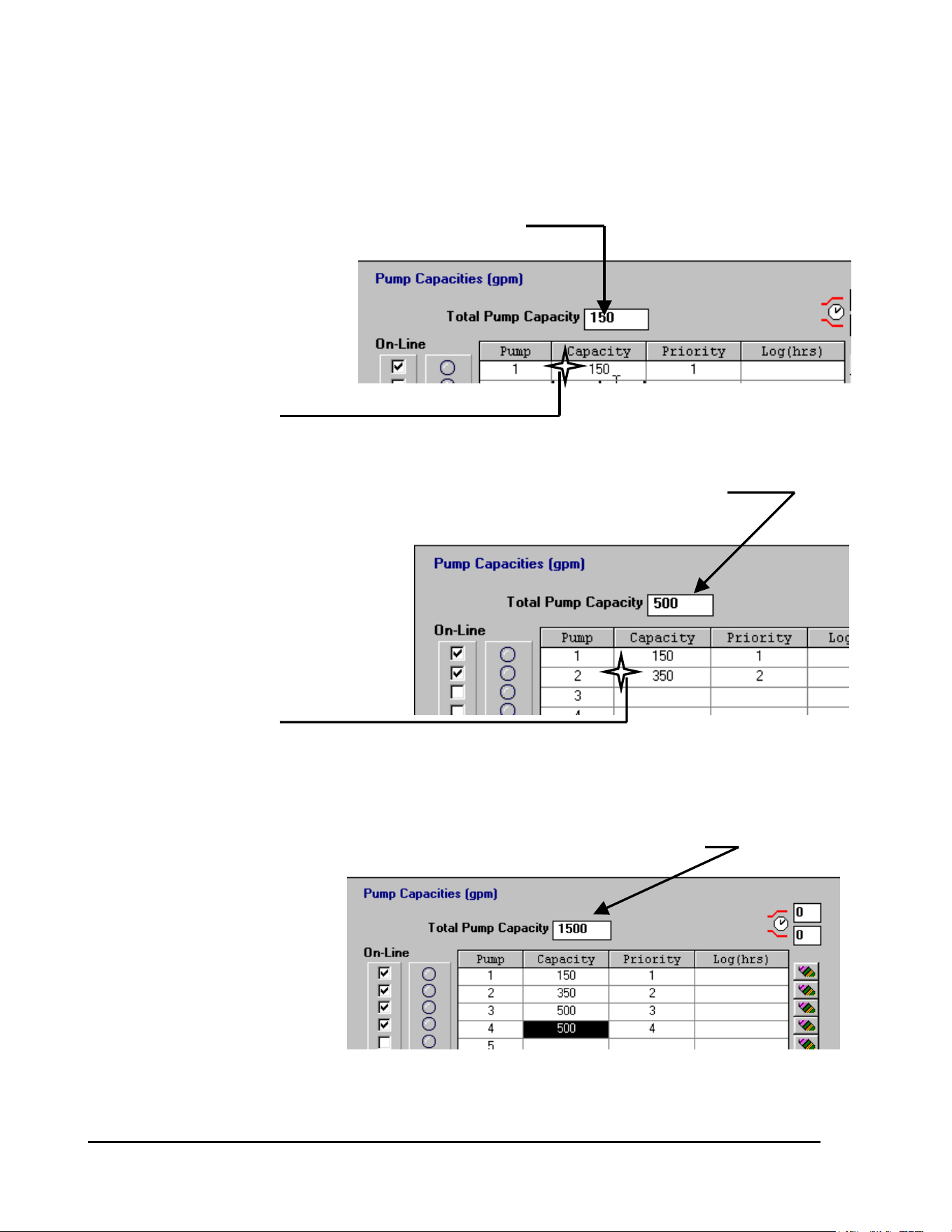
GT27141C Page 104 November 2003
TOTAL CAPACITY IS REFLECTED HERE
CLICK on the “Capacity” Cell
for Pump #1 and enter the
Pump Capacity – in our
example it is 150 GPM
CLICK ON “CAPACITY”
CELL AND ENTER GPM
SYSTEM CAPACITY AUTOMATICALLY UPDATES AND NEW PUMP IS ADDED
CLICK on the “Capacity” Cell
for Pump #2 and enter the
Pump Capacity - in our
example it is 350 GPM
CLICK ON “CAPACITY”
CELL AND ENTER GPM
AS EACH PUMP IS ADDED THE TOTAL SYSTEM CAPACITY IS UPDATED
Next CLICK on the “Capacity”
Cell for Pump #3 and enter
the Pump Capacity – in our
example it is 500 GPM
Repeat this procedure for
Pump #4 – entering the
capacity for it, which is
500 GPM
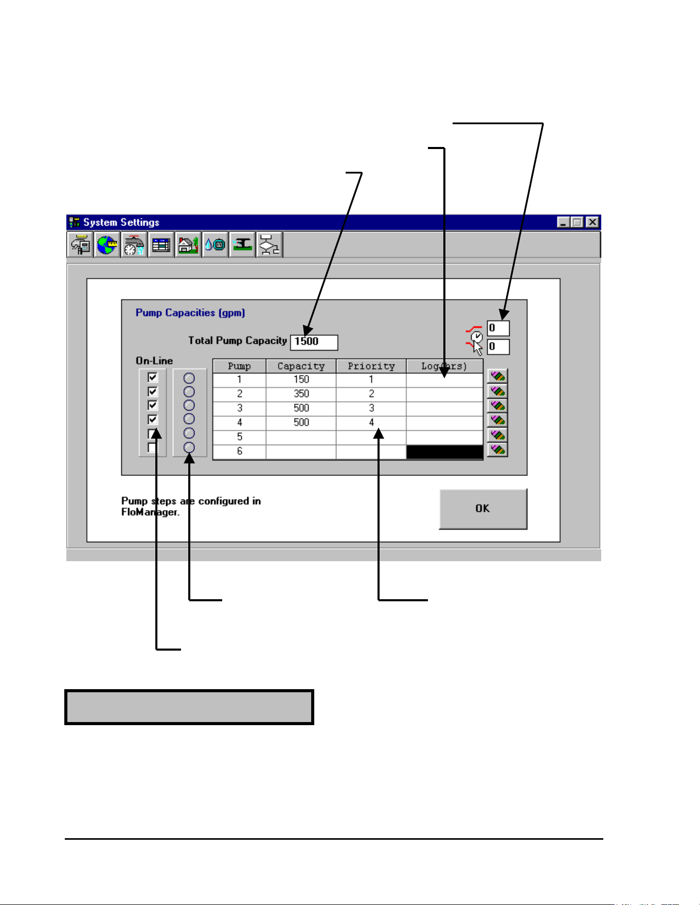
GT27141D Page 105 November 2003
Our PUMP TABLE would now look as displayed below.
PRE & POST PRESSURIZING TIMES CAN BE ENTERED HERE
OPERATING TIME FOR EACH PUMP WILL BE LOGGED HERE
TOTAL SYSTEM CAPACITY IS DISPLAYED HERE
LIGHT WILL INDICATE PRIORITY INDICATES THE
WHEN PUMP IS IN OPERATION ORDER IN WHICH EACH PUMP
WILL BE TURNED “ON”
EACH PUMP MAY BE TAKEN “OFF” LINE OR PLACED “ON’
LINE BY CLICKING ON THE “BOX” FOR PUMP DESIRED
The PRE & POST PRESSURIZING TIMES are in SECONDS. The “PRE PRESSURIZING
TIME” is the designated time, from the time the pump “STARTS” until any thing on the
system is actually turned “ON”. This allows time for the pump and the piping system to get up
to pressure before any irrigation or additional irrigation is allowed to take place.
PRE - PRESSURIZING TIME:
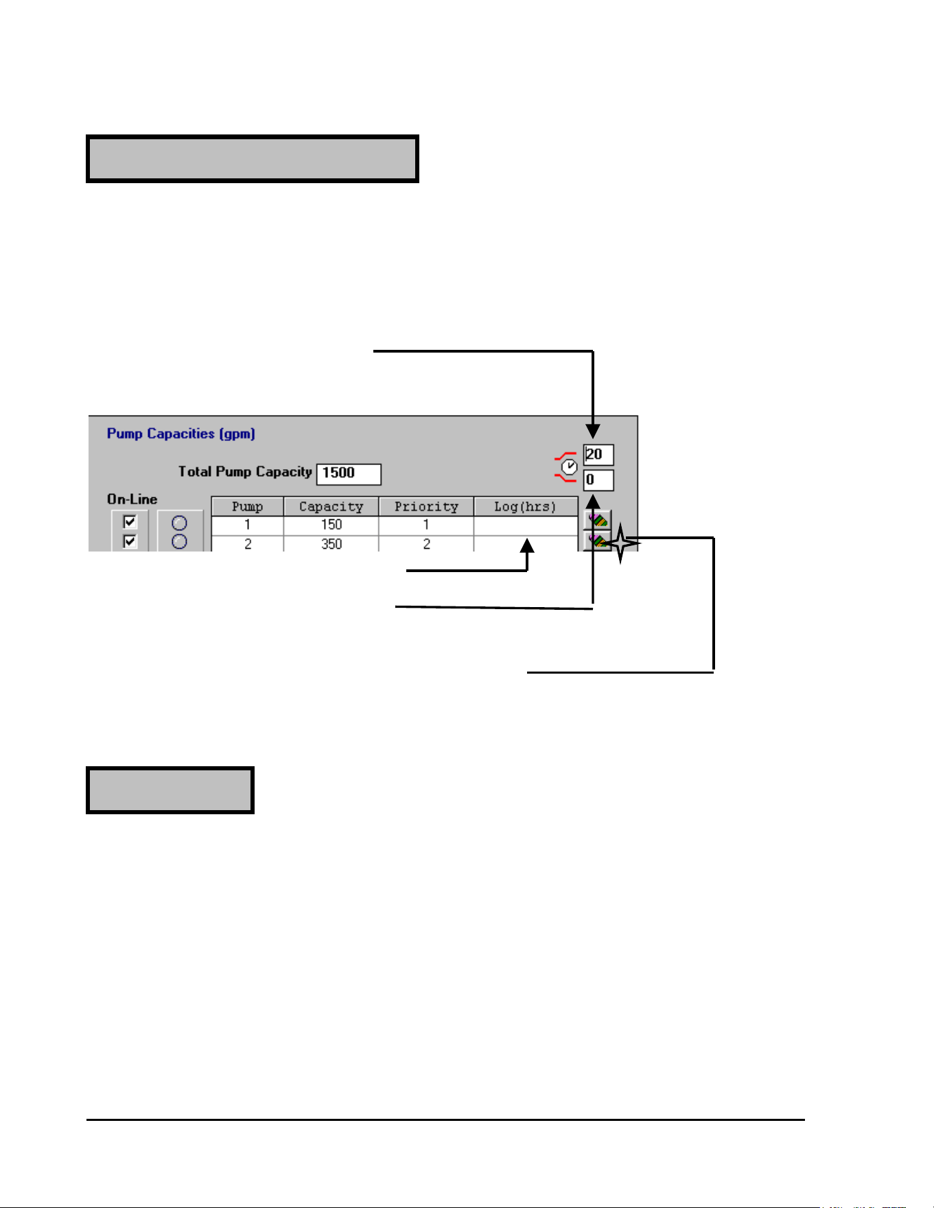
GT27141C Page 106 November 2003
The PRE & POST PRESSURIZING TIMES are in SECONDS. The “POST
PRESSURIZING TIME” is the designated time, from the time the irrigation is turned “OFF”
until the pump is actually turned “OFF”. This allows time for the piping system flow to
gradually be reduced, preventing water hammer in the system, before the pump is actually
turned “OFF”.
“PRE – PRESSURIZING TIME”
CLICK ON CELL AND ENTER
THE TIME DESIRED (IN SECONDS)
OPERATING “HOURS” ARE POSTED HERE
“POST – PRESSURIZING TIME”
CLICK ON CELL AND ENTER
THE TIME DESIRED (IN SECONDS)
THE OPERATION LOG (IN HOURS) CAN BE
“ERASED” BY CLICKING ON THE “ERASE”
BUTTON FOR THE DESIRED PUMP
A “PRIORITY” can be entered for each Pump. The Priority establishes in what order each
pump will be put into Operation. If Two (2) or more pumps are given the SAME Priority
number – then these pumps will ALTERNATE as to which will start FIRST one time and then
the other the next time, etc.
Normally a Priority Number (the same as the pump number) is entered automatically. This of
course can then be changed to what ever priority you wish for each of the pumps.
Once you have all the pump data entered correctly – then CLICK on the OK button to enter the
data permenently.
YOUR SYSTEM IS NOW PROGRAMMED FOR THE PUMP STATION OPERATION.
POST - PRESSURIZING TIME:
PRIORITIES :

GT27141D Page 107 November 2003
Rain Sensor for “Shut Down” of
Irrigation System upon a pre-determined
amount of Rain Fall:
The system is capable of incorporating a “RAIN SENSOR” for “SHUTTING DOWN” the
Irrigation System. The system is checking continuity and therefore only looking for the action
of a “DRY SWITCH” on the sensor (NO Voltage involved).
Normal MAXI cable can be used from the Rain Sensor back to the Line Termination Box. The
cable connects to the #7 and #8 Sensor Terminals on the left end of the terminal strip. Refer to
FIGURE: 6.4 shown below.
The Sensor Switch Action may be either “ON” (switch “closed”), which is referred to as
“Normally Open” – N.O. or may be “OFF” (switch “open”), which is referred to as “Normally
Closed” – N. C. when the sensor threshold is met. The switch position is specified when the
sensor is programmed into the system.
When the Rain Sensor is ACTIVE (has the system “Shut Down”), you may operate
decoders/valve-in-head sprinklers MANUALLY from either the central unit or by use of the
field transmitter or FREEDOM system.
Pump Alarm Sensor for “Shut Down”
Of Irrigation System upon a Pump Failure:
The system is capable of incorporating a “PUMP ALARM SENSOR” for “SHUTTING
DOWN” the Irrigation System. The system is checking continuity and therefore only looking
for the action of a “DRY SWITCH” on the sensor (NO Voltage involved).
Normal MAXI cable can be used from the Pump Alarm Sensor back to the Line Termination
Box. The cable connects to the #9 and #10 Sensor Terminals on the left end of the terminal
strip. Refer to FIGURE: 6.4 shown below.
The Sensor Switch Action may be either “ON” (switch “closed”), which is referred to as
“Normally Open” – N.O. or may be “OFF” (switch “open”), which is referred to as “Normally
Closed” – N. C. when the sensor threshold is met. The switch position is specified when the
sensor is programmed into the system.
When the Pump Alarm Sensor is ACTIVE (has the system “Shut Down”), the Pumps are
believed to have a failure and for that reason you may NOT operate decoders/valve-in-head
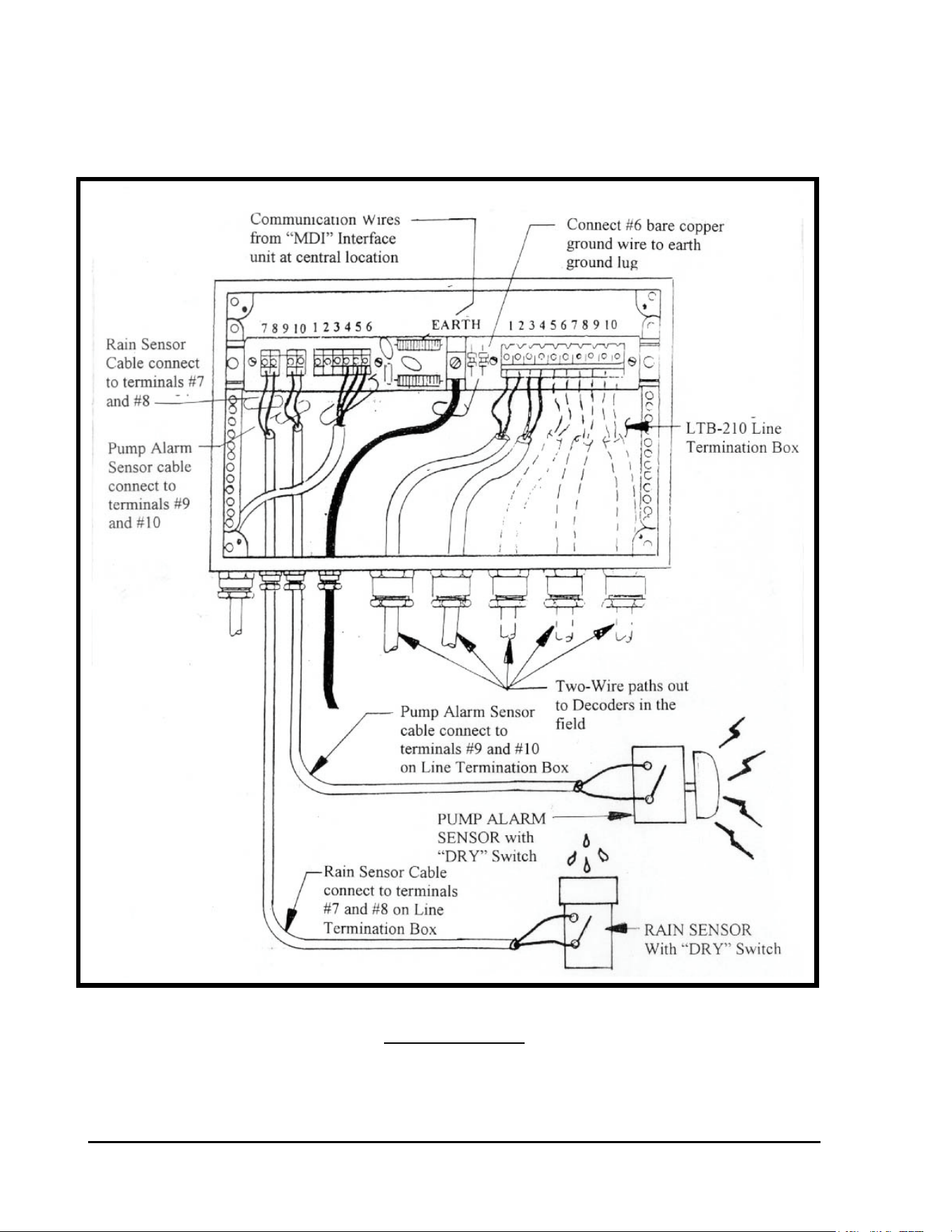
GT27141C Page 108 November 2003
sprinklers MANUALLY from either the central unit or by use of the field transmitter or
FREEDOM system.
SENSOR CONNECTIONS TO LINE TERMINATION BOX
FIGURE: 6.4

GT27141D Page 109 November 2003
Chapter
7
Troubleshooting the
Decoder System
The Two-Way Communication of the Rain Bird Decoder
System Provides Powerful Diagnostic Capabilities at the
Central Location for Easy Troubleshooting of the System.
Troubleshooting is an art. But it is based on a logical sequence of thought. In this section,
troubleshooting guidelines will be presented. Using these trouble-shooting procedures, the
Decoder system is easy to service and maintain.
This chapter is broken into two sections. All troubleshooting of a Rain Bird Decoder System
should start at the CENTRAL LOCATION. This will be the first section of this chapter. After
diagnosing the problem at the Central Location, troubleshooting can then proceed in the FIELD.
This will be the second part of this chapter.
Troubleshooting from the Central Location
Troubleshooting of a Decoder System at the Central Location entails using the Rain Bird
Decoder System Diagnostics. The Software programs have a Decoder Diagnostics function that
enables the software to perform diagnostics on the decoders and the Two-Wire Communication
Path. These Decoder Diagnostics can be used alone without a Line Test unit as the software
puts the interface unit (MDI, LDI or SDI) into a current limiting mode when the diagnostics are
brought on line and the interface unit is placed in a 60 Hz mode for troubleshooting the system.
In this section, diagnostic testing will be discussed using the Decoder Diagnostics. Finding field

GT27141C Page 110 November 2003
faults will require the use of a sensitive clamp meter capable of reading as little as a few
milliamps (mA). Contact you Rain Bird Golf Distributor for details.
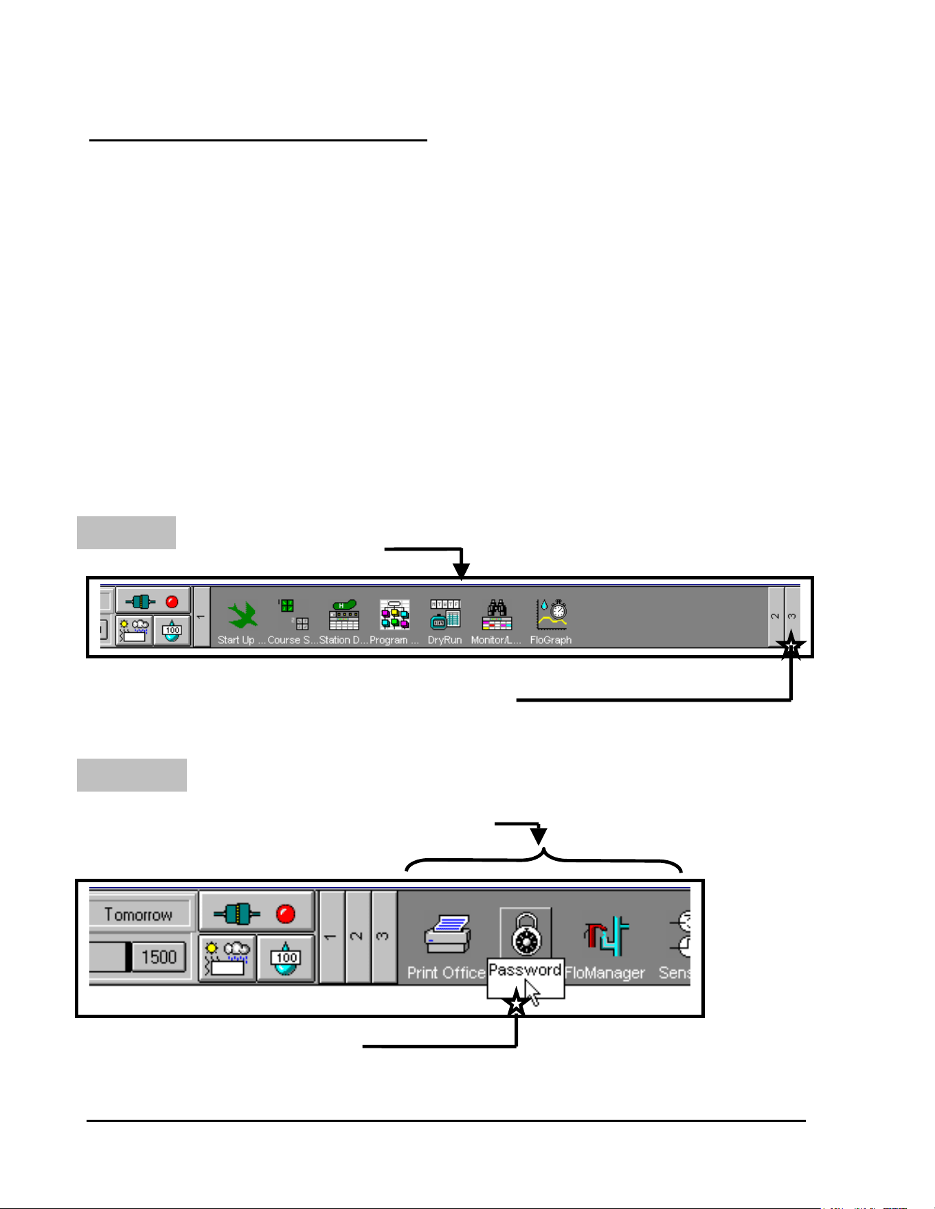
GT27141D Page 111 November 2003
DECODER DIAGNOSTICS - USING STRATUS,
STRATUS II, NIMBUS, NIMBUS II or CIRRUS
SOFTWARE
There are SIX tests that can be run on the Decoder System, by using the software, and
which facilitate troubleshooting of the system. These tests can be run by using the
STRATUS, STRATUS II, NIMBUS, NIMBUS II or the CIRRUS software in conjunction with
the MDI Interface Unit and do not require any additional equipment. These are different tests
from those tests run by the Line Test Unit only, but the results should be used in conjunction
with the Line Test Unit results to pinpoint problems in the field.
To access the Decoder System DIAGNOSTICS, you need to start at the FRONT
OFFICE screen of the particular software you are using.
STEP #1: CLICK ON #3 ICON
FRONT OFFICE SCREEN
CLICK ON THE #3 ICON
The third group of Icons will now be displayed as shown below.
STEP #2: CLICK ON “PASSWORD” ICON
#3 GROUP OF ICONS BEING DISPLAYED
CLICK ON THE “PASSWORD” ICON
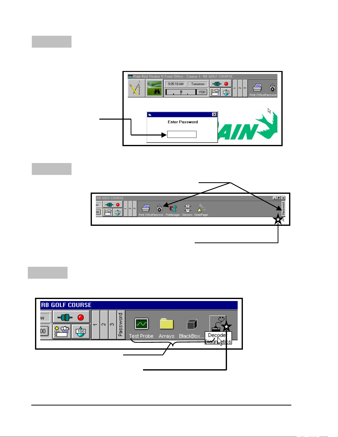
GT27141C Page 112 November 2003
STEP #3:
STEP #4:
ENTER PASSWORD “4321”
The system will now ask for you to enter the “Password”, which is “4321”.
After entering the “Password”
Then Press <ENTER>
ENTER “4321” (Password)
THEN PRESS <ENTER>
CLICK ON “PASSWORD” ICON
Padlock is “Unlocked” and “PASSWORD” Icon is displayed
CLICK ON “PASSWORD” ICON
Click on the “PASSWORD” Icon at the top, far right side of the screen.
STEP #5: CLICK ON THE “DECODER” ICON
The following ICONS will now be displayed on the right side of the header screen.
NEW ICONS NOW DISPLAYED
CLICK ON THE “DECODER” ICON
Click on the “DECODER” Icon now being displayed.
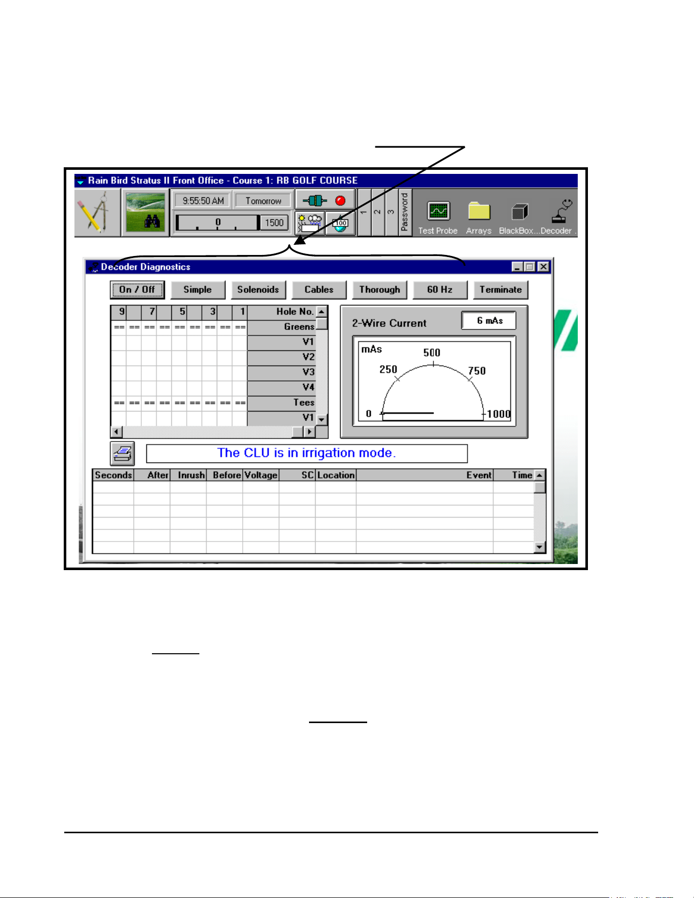
GT27141D Page 113 November 2003
The first Decoder Diagnostics screen will now be displayed, as shown below.
SIX DECODER DIAGNOSTIC TESTS AVAILABLE
RUNNING THE DECODER DIAGNOSTIC TESTS:
(Tests MUST be run in sequence)
As you see from the screen displayed above, there are six (6) TESTS in the decoder diagnostics
window. These six tests should always be performed in their PROPER SEQUENCE because
the results from previous tests are used to interpret the results of subsequent tests. The first few
tests look for very general problems while the latter tests look for very specific problems. The
latter tests cannot be performed until after all of the problems found during the earlier tests have
been resolved.
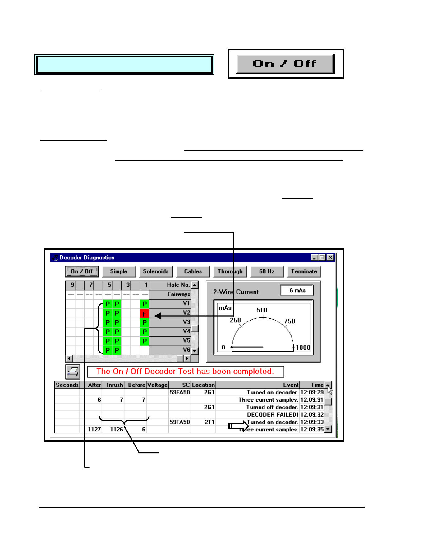
GT27141C Page 114 November 2003
TEST #1: ON/OFF DECODER TEST
OBJECTIVE: To determine whether or not each decoder will respond
to the standard “ON” command.
This test is useful for determining which decoders will respond properly during irrigation, but it
does not indicate any degradation of the decoders or the lines.
PROCEDURE: Each decoder is sent its usual switchcode and an “ON”
command. - Bear in mind, if you are checking a system
which is pressurized, the valves will be activated briefly.
The current in the two-wire path is measured before, during and after the activation of the
decoder to determine whether or not the decoder responded to the “ON” command. Each
decoder is then turned “OFF”. The decoders that did not respond to the “ON” command will be
tagged with an “F” in a “RED” background field, to indicate that they FAILED this test. The
decoders that did respond to the “ON” command will be tagged with a “P” in a “GREEN”
background field, to indicate that they PASSED this test.
INDICATES DECODER “FAILED” THE TEST
(“F” in a red background cell)
NEITHER “INRUSH” OR “AFTER” CURRENT EXCEEDED THE
“BEFORE” CURRENT – THUS DECODER “FAILED” THE TEST
INDICATES DECODER “PASSED” THE TEST

GT27141D Page 115 November 2003
DETAILS: Three current samples are taken at 40 millisecond
intervals.
The first sample is the “BEFORE” current. The second sample is the “INRUSH” current. The
third sample is the “AFTER” current. IF EITHER THE “INRUSH” or THE “AFTER”
CURRENT EXCEEDS THE “BEFORE” CURRENT BY 25 mA or MORE, THEN THE
DECODER “PASSES” THE TEST. Otherwise, the decoder fails.
COMMENTS: During the test, each decoder receives the same
information that it receives during irrigation.
This test simply tells us whether or not each decoder can be turned “ON” and “OFF”. There are
NO warning messages displayed during this test, other than the “DECODER FAILED”
notation in the data recording area of the test window.
CAUSES for DECODER FAILURE:
There are six (6) possible causes for a decoder to fail the ON/OFF test.
1
st
– Check and double check the decoder ADDRESS. A number inadvertently written down
incorrectly or perhaps a missed keystroke during data entry will cause a decoder to FAIL.
2
nd
– On a new system “start-up”, missed or poorly made wire SPLICES, are the cause of
most decoder FAILURES. A missed mainline splice, as at a three-way branch
location, will cause any decoder that is “downstream” from that point to FAIL. These
are very easy to locate with a good “as-built” plan of thesystem layout. Remember ALL
SPLICES must be located properly in valve boxes for easy accessability.
3
rd
– Missed or poorly made wire splices at the decoders will also cause a decoder to FAIL.
Both the BLUE communication wires from the decoder to the MAXI communication
cable and the WHITE output wires from the decoder to the solenoid coil MUST be
twisted, then wire nutted and finaly placed in a DBY or DBR splice kit.
4
th
– If there is secondary wiring used between the decoder output and the valve solenoid coil,
it must be checked for continuity and/or resistance to assure a good circuit from the
decoder to the valve and back.
If you have checked the secondary wiring from the point where it is spliced to the
decoder output wires and have an “open” indication, then check the solenoid itself. If it
is fine, then the problem is either a bad splice at the solenoid or a broken secondary wire,
which will then need to be traced by using a fault finder on it.

GT27141C Page 116 November 2003
ACTION TO BE TAKEN
:
First, check the integrity of the splices,
secondary wiring and the solenoid itself.
If all are fine, then decoders that failed
this test are NOT suitable for irrigation
and should be replaced at this time.
If the warning message “EXCESSIVE CURRENT DETECTED” is displayed at the
beginning of this test, then there is most likely a problem somewhere in the two-wire
path. The user should CONTINUE this test and check to see if there is a
g
roup o
f
decoders in a particular area that all fail this test. If so, the user should check the wires
in that region. Otherwise, the user should put the MDI into a 60 Hz mode and inspect
the two-wire path with a clamp meter to find the short or leakage. The excessive
current problem MUST be resolved before test #3, #4 & #5 can be performed.
5
th
– The SOLENOID itself may be “open”, which will cause a decoder that is actually
working, to give a false “FAIL” indication.
6
th
– Lastly, the DECODER itself may be “bad” and simply not function.
ALL OF THESE POSSIBILITIES MUST BE EXPLORED AND CORRECTED.
WARNINGS:
A failure in the “SIMPLE DECODER TEST” can indicate a number of things. It may mean that
the decoder has been damaged by a voltage surge, but more likely, a failure indicates a problem
in the wiring between the two-wire path, the decoder, and the solenoid.
The first step is to check the integrity of the two-wire path’s connection to the decoder itself.
These splices must be intact and must NOT be leaking to ground. If the splices are NOT intact,
the decoder will not be powered correctly and therefore cannot be controlled by the MDI
Interface unit. The decoder itself can be checked simply by connecting it in place of another
good decoder and running the “Simple Decoder Test” again.
If a decoder that is functioning correctly fails the “Simple Decoder Test”, the indication is that
there is a problem on the secondary wire path, the wiring between the decoder and the solenoid.
A decoder will fail if there is a ground fault in one of the splices on the secondary path or if the
secondary path is not intact. In either case, the secondary path does not provide an integral path
for the current from the decoder to travel to the solenoid to activate it.
GT27141D Page 117 November 2003
TEST #2: SIMPLE DECODER TEST
A decoder will NOT FAIL the “Simple Decoder Test” if the secondary path is SHORTED. If
the path is shorted, or if the solenoid itself is shorted, the decoder will attempt to power the
solenoid, but the solenoid will not activate. However, because the decoder is still functioning,
it will PASS the “Simple Decoder Test” even if a solenoid is shorted.
OBJECTIVE: To determine whether or not each decoder and its
solenoid are working properly.
PROCEDURE: Before testing each of the decoders, the current in the
two-wire path is measured, in order to determine if it is
STABLE and BELOW an acceptable limit.
If the current in the two-wire path is STABLE and BELOW the acceptable limit, then each
decoder is activated with a special switchcode that is based upon the resistance of the solenoid
that is connected to the decoder. This special switchcode reduces the inrush voltage from
standard 35 volts to 26 volts and in effect changes the effective resistance of the solenoid to 45
ohms. When the decoder is activated, the inrush current will then indicate the solenoid’s
resistance. If the resistance is less than or greater than 45 ohms
, the inrush current won’t be
measured by the MDI, which is looking for a minimum of 25mA. The solenid has either been
damaged by lightening or has a mechanical problem. The decoders that respond properly to this
special switchcode are tagged with a “P” displayed on a “GREEN” background, indicating that
they have “PASSED” this test. The decoders that did NOT respond properly to this special
switchcode are tagged with an “F” displayed on a “RED” background, indicating that they have
“FAILED” this test.
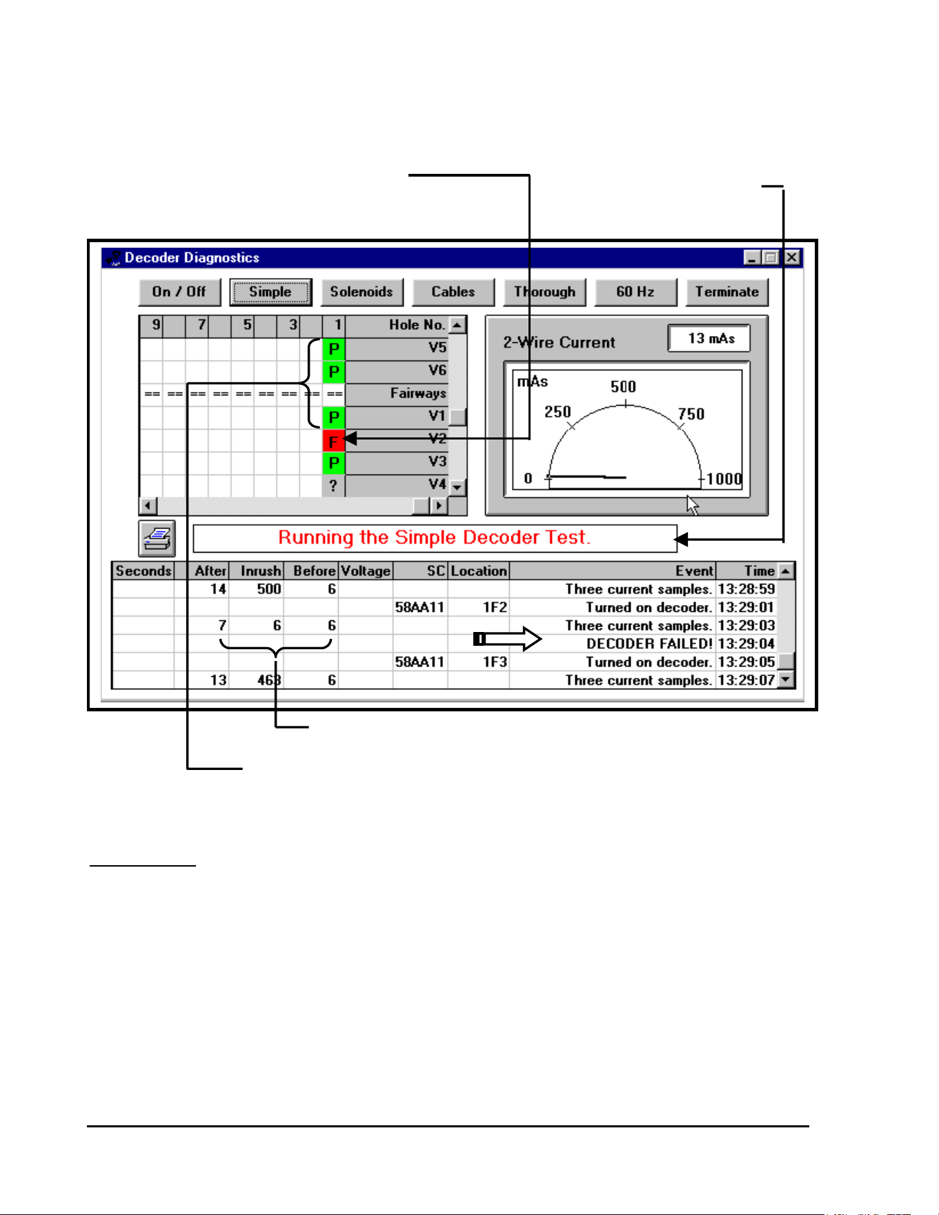
GT27141C Page 118 November 2003
INDICATES DECODER “FAILED” THE TEST
(“F” in a red background cell) INDICATES SIMPLE DECODER
TEST IS IN PROGRESS
CURRENTS INDICATE DECODER “FAILED”
INDICATES DECODER “PASSED” THE TEST
(“P” in a green background cell)
DETAILS: Before beginning this test, the current in the two-wire
path is checked.
GIVEN: Let “X” = the number of FD-210/FD-102 type decoders on the system.
Let “Y” = the number of FD-410/FD-202, FD-401 and/or FD-610/
FD-601 decoders on the system.
FORMULA: I Acceptable = [(“X” x 0.5 mA) + (“Y” x 1.0 mA)] x 1.25 + 100 mA

GT27141D Page 119 November 2003
If there is excessie current, it is usually the result of a short in the line or a short in a
decoder, or excessive leakage to ground by either a FAULT in the two-wire path or
leakage to ground by a decoder.
Single CHANNEL Decoders (FD-210/FD-102) theoretically draw a nominal current of 0.5 mA
of current.
Multiple CHANNEL Decoders (FD-410/FD-202, FD-401 and FD-610/FD-601) theoretically
draw 1.0 mA of current.
The factor 1.25 allows for a 25% error of margin. The 100 mA is the limit of excessive current
consumption. If the current in either line of the two-wire path EXCEEDS this limit, then a
warning message will be displayed, as shown below.
“EXCESSIVE CURRENT DETECTED”
After the current in each of the lines has been measured, each decoder will be activated with a
special switchcode. During the activation, five current samples are taken at 60 millisecond
intervals. The first sample is the “BEFORE” current. The MAXIMUM of the second, third
and fourth samples is taken as the “INRUSH” current. The fifth sample is the “AFTER”
current.
Let “X” = the number of decoders (both single and multiple channel type) on the
two-wire path.
A DECODER “PASSES” the test if . . .
`I Inrush < 1050 mA
and
I Inrush > 300 mA + [0.5 mA x (“X” – 250)]
and
I After > I Inrush - 50 mA
GT27141C Page 120 November 2003
TEST #3: GROUNDED SOLENOID TEST
Failure of this test indicates that either the decoder or its solenoid is damaged. If a
decoder and its solenoid fail this test, then you should run the next test, “Grounded
Solenoids Test”, to determine if the problem is in the decoder or in the solenoid.
If a group of decoders, all in the same area fail this test, then the problem is most likely
Damaged lines in that region rather than in the decoders themselves. Therefore the
lines in that area should be checked with a clamp meter.
If a group of decoders in the same area fail this test due to low current consumption,
then the problem may be due to a bad connection in the two-wire path, which is causing
excessive resistance in the lines. If this is the case, the two-wire path should be
inspected with a clamp meter.
COMMENTS: This test can only be performed on decoders that have
solenoids with a resistance of 50 ohms or less.
ACTION TO BE TAKEN:
OBJECTIVE: To determine if any of the solenoids are leaking
excessively to ground.
This test is useful for determining the severity of a solenoid’s leakage to ground.
PROCEDURE: Each decoder is reprogrammed to address “0000”.
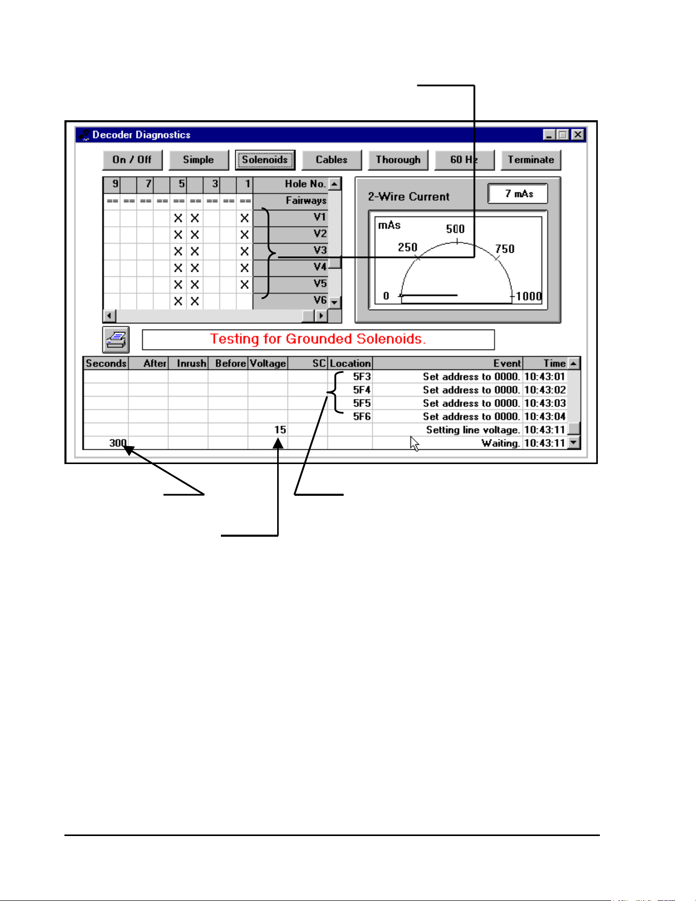
GT27141D Page 121 November 2003
INDICATES DECODER HAVING BEEN RESET TO ADDRESS “0000”
INDICATES WAIT INDICATES DECODER HAVING BEEN
TIME PERIOD REPROGRAMMED TO ADDRESS “0000”
TEST VOLTAGE SELECTED
After each decoder has been reprogrammed to address “0000” & with the two lines of the 2-wire
path clamped together, then the specified test voltage (15 volts, 25 volts, or 35 volts) is applied
for a period of five minutes (refer to screen displayed above).
During this time, only the decoders with solenoids that leak excessively to ground will be able to
maintain their new address of “0000” sue to the leadage current continuing thru the decoder and
not allowing the code to be reset on return of the normal line condition. The decoders with
solenoids that do NOT leak excessively will lose their new address of “0000” and will
automatically be reset to their original addresses on return of the normal line conditon. After the
five minute wait has been completed, the lines will be reactivated and then each decoder will be
tested to see if it responds to its original address. Those decoders that do not respond have
solenoids that are leaking excessively to ground and will be tagged with an “F” on a RED
background, indicating that the decoder has “FAILED” this test. Those decoders
that have been tagged with a “P” on a GREEN background are indicating that the decoder has
“PASSED” this test.
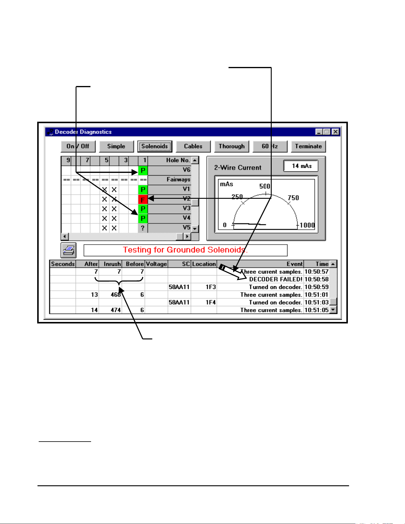
GT27141C Page 122 November 2003
INDICATES THAT THIS DECODER HAS “FAILED” THE TEST
(Tagged with an “F” on a RED background cell)
INDICATES THIS DECODER HAS “PASSED” THE TEST
(Tagged with a “P” on a GREEN background cell)
CURRENTS INDICATE DECODER
HAS “FAILED” THIS TEST
If any of the decoders fail this test, then the two-wire path will be tristated for a period of three
(3) minutes. (Refer to the screen displayed on the next page.) During this time, the decoders
that still have an address of “0000” will go through an automatic reset and will then respond to
their original addresses.
DETAILS: Three test voltages are available so that the user may
distinguish those decoders with solenoids that are
leaking excessively to ground from the decoders with
solenoids that are leaking only slightly.
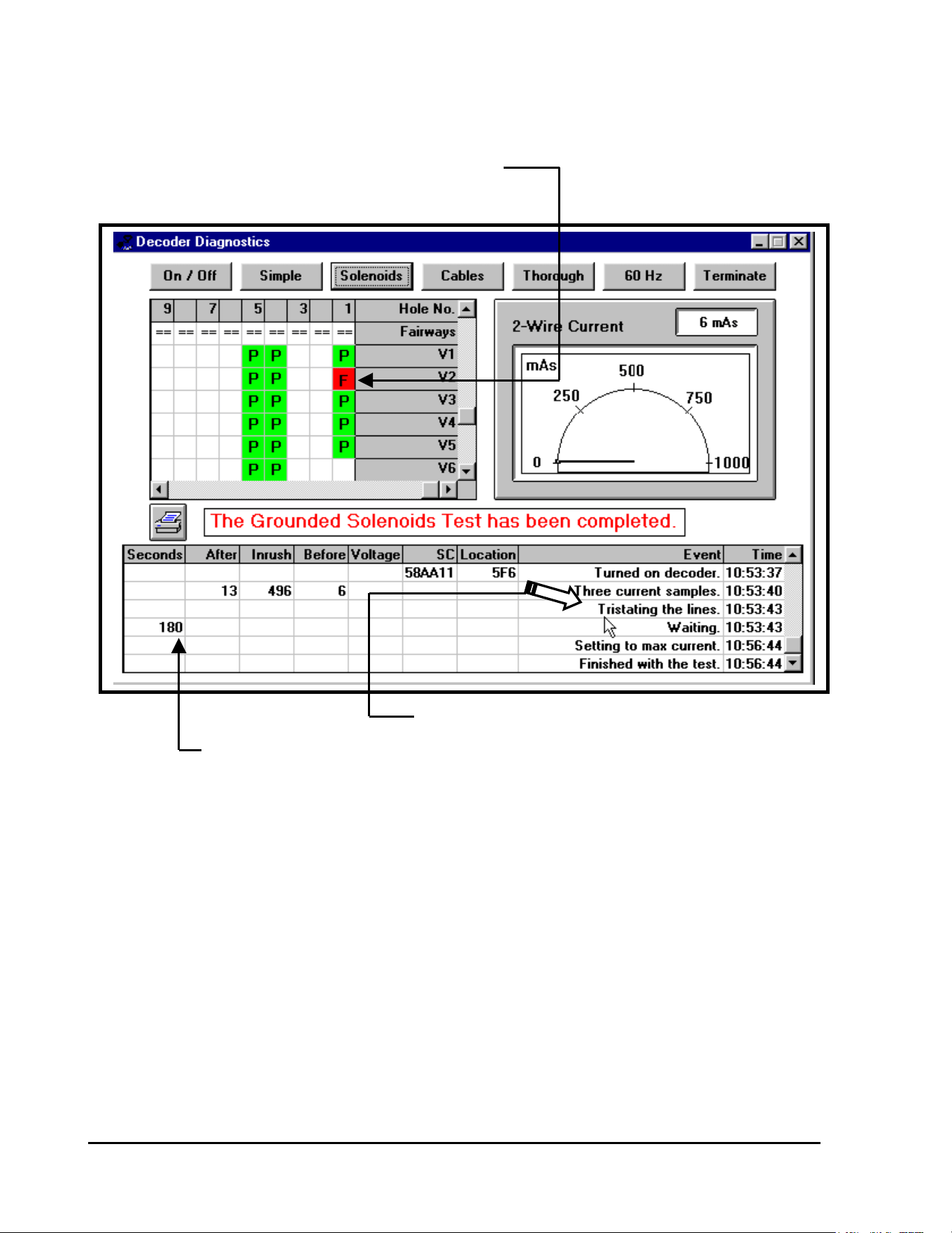
GT27141D Page 123 November 2003
INDICATES DECODER THAT HAS “FAILED” THIS TEST
(Tagged with an “F” on a RED background cell)
INDICATES TWO-WIRE PATH BEING TRISTATED
INDICATES WAIT PERIOD
Decoders that FAIL at the low test voltage of 15 volts have solenoids that are leaking
excessively to ground. Decoders that PASS at the low test voltage of 15 volts but FAIL at the
high test voltage of 35 volts have solenoids that are leaking only slightly to ground.
After the two-wire paths have been locked at the specified voltage for five (5) minutes and then
reestablished for one minute, the “SIMPLE DECODER TEST” is performed. Refer to the
section for “TEST #2: SIMPLE DECODER TEST” for interpretation of the test results.
GT27141C Page 124 November 2003
If a Decoder FAILS this test, then the electrical connections from the decoder to its
solenoid should be inspected. If the connections are leaking to ground, then the
connections should be repaired. Otherwise, the solenoid itself is leaking and it must
eventually be replaced.
Decoders that FAIL this test at 15 VOLTS should have their solenoids and connections
inspected at the next convenient opportunity.
Decoders that FAIL this test at 35 VOLTS have solenoids that are still functioning
satisfactorily but they should be tested more frequently in case there is further
degradation.
TEST #4: GROUNDED CABLES TEST
ACTION TO BE TAKEN:
OBJECTIVE: To determine if either wire in the two-wire path is
leaking excessively to ground.
This test is useful after the system has been struck by lightning or the wires have been serviced.
PROCEDURE: The current in each of the wires of the two-wire
path is measured to determine if it is stable and
within a specified range.
If the currents in both lines are stable and within the acceptable range, then the current in the
ground line is measured and the voltage at the case is measured. If either the current or voltage
is not within the specified range, then the user is warned of an error condition.
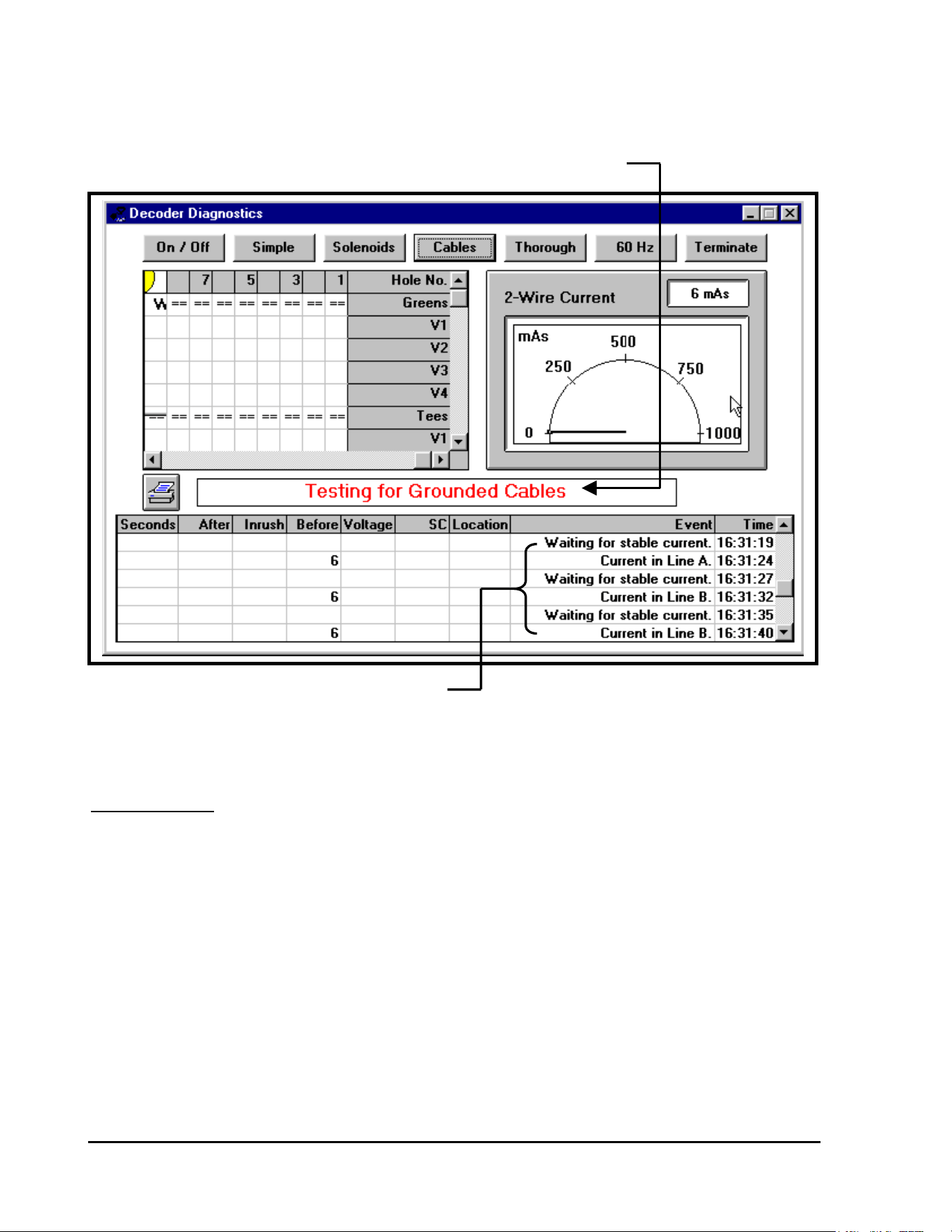
GT27141D Page 125 November 2003
INDICATES THAT “TESTING FOR GROUNDED CABLES” IS IN PROGRESS
CHECKING CURRENT IN BOTH LINES “A” & “B”
OF THE TWO-WIRE PATH
DETAILS: The lines of the two-wire path are locked – Line “A” is
locked “HIGH” and Line “B” is locked “LOW”.
With the lines of the Two-wire path now locked, with line “A” locked “HIGH” and line “B”
locked “LOW” – the system takes two sets of three (3) current samples. The average of each set
of samples is calculated and then the difference between the two averages is determined. If the
difference is LESS than 5 mA, then the current is considered STABLE.
Then the lines are reversed and locked, with line “A” locked “LOW” and line “B” locked
“HIGH” – the system again takes two sets of three (3) current samples. The average of each set
of samples is calculated and then the difference between the two averages is determined. If the
difference between the first average and the second average is LESS than 5 mA, then the current
is considered STABLE.

GT27141C Page 126 November 2003
The maximum theoretical current consumption in each line of the two-wire path is calculated
by:
I Line = [(“X” x .5 mA + “Y” x 1.0 mA) x 1.25 ] + 10 mA
Where: “X” = Number of Single Channel Decoders
Such as: FD-210/Fd-102 Decoders
“Y” = Number of Multple Channel Decoders
Such as: FD-410/FD-202, FD-401 &
FD-610/FD-601
If the current in either line exceeds this value, then the user is warned about “EXCESSIVE
LINE CURRENT”.
The Minimum theoritical current consumption in each line of the two-wire path is calculate by:
I Line = [(“X” x .5 mA + “Y” x 1.0 mA) ÷ 1.25] – 10 mA
Where: “X” = Number of Single Channel Decoders
Such as: FD-210/Fd-102 Decoders
“Y” = Number of Multple Channel Decoders
Such as: FD-410/FD-202, FD-401 &
FD-610/FD-601
If the current in either line is below this value, then the user is warned about “INSUFFICIENT
LINE CURRENT”.
GT27141D Page 127 November 2003
Warning: Excessive current
detected
The 60 Hz mode test should then be used, in conjunction with the Clamp Meter to find the
location of the leakage.
COMMENTS: Before running this test it is imperative that all of
the decoders in the system passed the previous
test at 15 Volts.
If all of the decoders passed the previous test, then we know that they are not leaking
excessively to ground. Therefore, if this test indicates that there is excessive leakage, we know
the leakage must be from the lines rather than from the decoders.
WARNING MESSAGE:
So if the message “Warning: Excessive current detected” is displayed, then there is leakage
either from a wire to ground or from one wire to the other wire in the two-wire path.
ACTION TO BE TAKEN:
WARNING MESSAGE:
There is another warning message that may be displayed – “Warning: Insufficient Current
Detected”. This message is included only for the sake of completeness; the only time that
insufficient current would be detected is if the database includes extra decoders that are not
actually connected to the two-wire path.
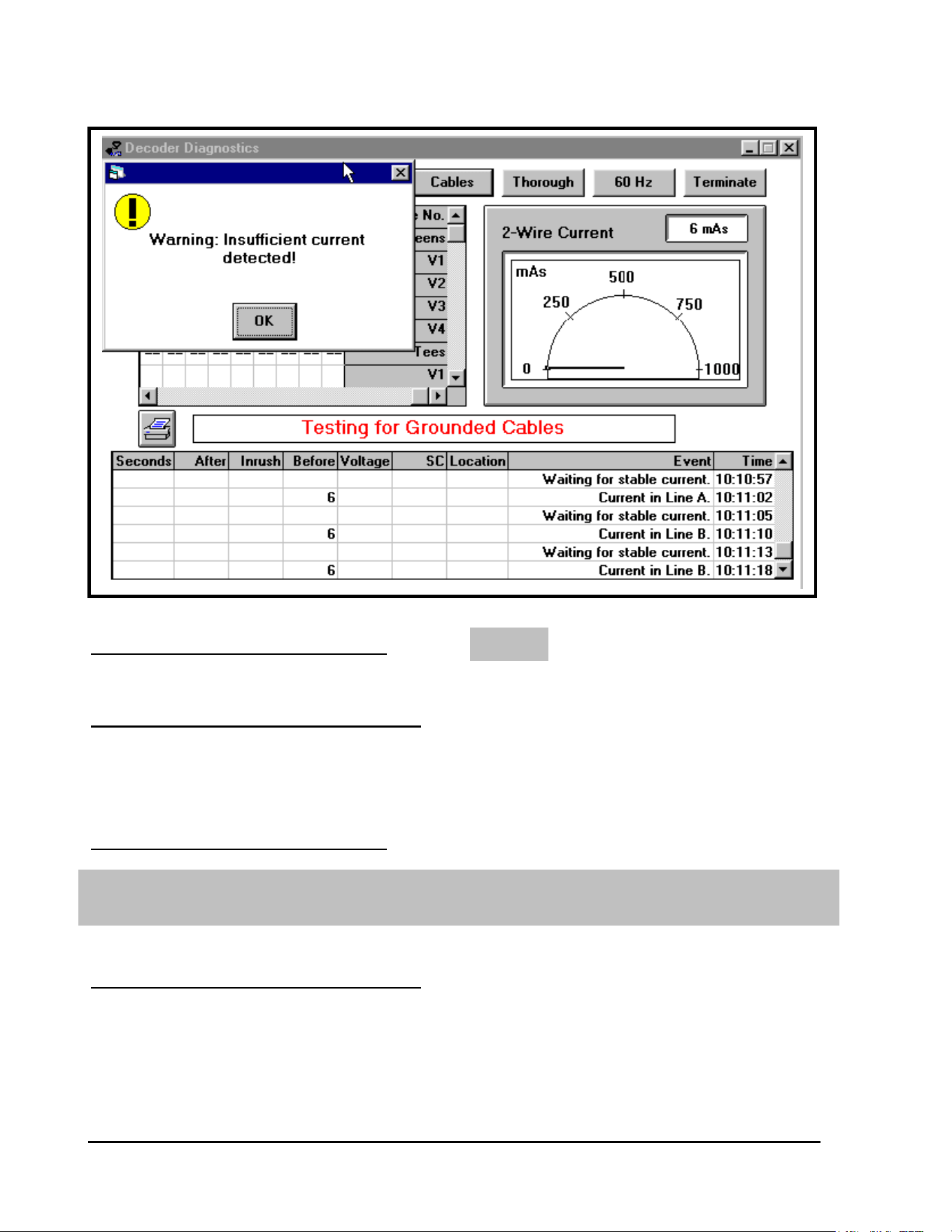
GT27141C Page 128 November 2003
NONE
The 60 Hz test mode should be used, in conjunction with a Clamp Meter
to find the location of the leakage and proper correction should be made.
ACTION TO BE TAKEN:
ADDITIONAL COMMENTS: If the current in the ground line exceeds
15 mA, then the message “Warning: Current in Ground Line Exceeds 15 mA” will be
displayed. If this message appears, then there is leakage from one of the wires to ground.
ACTION TO BE TAKEN:
ADDITIONAL COMMENTS: If the voltage on the ground line
exceeds 17.5 volts, then the
message “Warning: The Voltage at
the Case Exceeds 17.5 Volts” will
be displayed.
GT27141D Page 129 November 2003
The 60 Hz test mode should be used, in conjunction with a Clamp Meter to
find the location of the leakage and proper correction should be made.
The two-wire path should be disconnected from the MDI Interface Unit
and this test should be run again.
TEST #5: THOROUGH DECODER TEST
This situation can be caused either by very heavy leakage from a wire to ground, or by a
problem with the MDI Interface Unit.
ACTION TO BE TAKEN:
If the current in the ground line was reported as excessive, then the problem is due to leakage
from the ground wire.
This problem should be solved IMMEDIATELY because it will cause
corrosion to the cables.
If the current in the ground line was NOT HIGH and this warning message is displayed;
If the voltage at the ground line is still HIGH, then the MDI Interface Unit
is defective.
OBJECTIVE: To determine if the internal current consumption of
each decoder is low enough to insure that the capacitor
in the decoder will be capable of activating the solenoid.
This test is useful for identifying decoders with deteriorating hardware. Decoders that fail this
test may still operate properly during irrigation, but they should be replaced due to imminent
failure.
PROCEDURE: Each decoder is sent a special switchcode, which
is calculated from the decoder’s solenoid
resistance.
GT27141C Page 130 November 2003
TEST #6: 60/50 Hz TEST
This switchcode is the same one that was described previously in the “Simple Decoder Test”.
After sending all of the switchcodes, the line voltage is truned “OFF” for 20 seconds. During
this 20 second wait, the decoders that have excessive internal current consumption will not be
able to maintain the special switchcodes. After the 20 seconds have elapsed, the lines are
reactivated and the system waits for 60 seconds to let the lines power up and stablize. Then
each decoder is sent an “ON” command without a switchcode. The decoders that fail to respond
to this “ON” command have lost their swtichcodes so they are tagged with an “F” on a RED
background cell, indicating that their internal currrent consumption is too high.
DETAILS: The normal current consumption of a single channel
decoder is 0.5 mA and the normal current consumption
of a multiple channel decoder is 1.0 mA.
If the internal current consumption of a decoder exceeds 15 mA, then when the line voltage is
turned off for 20 seconds, the capacitor will be discharged to a voltage that is too low to
maintain the decoder’s switchcode. Therefore, the decoder will lose its switchcode and will
NOT respond to the “ON” command. After the line voltage had been turned off and then
reactivated, the “Simple Decoder Test” is performed. (Refer to Section for Simple Decoder
Test – Test #2).
OBJECTIVE: To assist the user in finding shorts in the two-wire
path and leakage from wire to wire or from wire to
ground.
PROCEDURE: The user puts the MDI Interface Unit into the 60/50 Hz mode and
then inspects the two-wire path at various points with a Clamp Meter. The Clamp meter will
show where the signal in the two-wire path is active and where the signal is being lost due to
either shorts in the cable or from leakage to ground.
COMMENTS: The MDI Interface Unit communicates with the decoders on the
two-wire communication path through an approximate 34 Volt AC signal. The AC signal is
used to prevent corrosion of the two-wire path. The AC signal is normally alternating at a
frequency of 1 Hz, meaning it switches from positive to negative once every second, which is
the RED to GREEN alternating you see on the MDI’s “Field” LED.
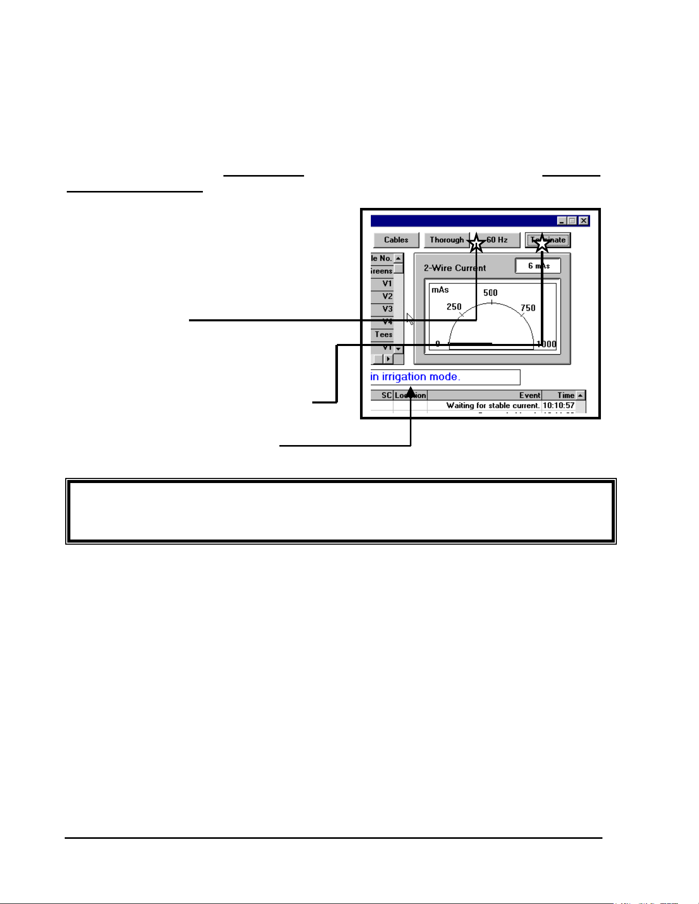
GT27141D Page 131 November 2003
IMPORTANT! Since NO Irrigation can take place while in the 60 Hz mode – it is
extremely important that you place the system back into the “Irrigation Mode” when finished
with the field troubleshooting.
To measure the current on the two-wire path for troubleshooting in the field a Clamp Meter is
used. The frequency of the AC signal must then be increased by the MDI Interface Unit in order
to allow the Clamp Meter to measure the signal. When running the 60 Hz Mode test, the AC
signal is changed from a 1 Hz signal to a 60 Hz signal. In the 60 Hz mode, the MDI cannot
communicate with the decoders, so no irrigation can take place. Therefore, upon completing
this test, it is important to TERMINATE the test and thus return the MDI to the “NORMAL
IRRIGATION MODE”.
The 60 Hz Mode is started by clicking on
the 60 Hz ICON in the Decoder Diagnostics
screen. When the MDI Interface Unit is in the
60Hz mode, the “Field” LED will appear an
ORANGE color as the AC signal is not at
60 cycles per second.
CLICK ON 60 Hz ICON
The current of the MDI can then be measured
in the field using the Clamp Meter.
THE 60 Hz MODE CAN THEN BE CANCELLED
BY “CLICKING” ON THE “TERMINATE” ICON
THE SYSTEM HAS NOW BEEN PLACED
BACK INTO THE “IRRIGATION MODE”

GT27141C Page 132 November 2003
Troubleshooting in the Field
After running the Decoder Diagnostics tests from the Central Software, the troubleshooter
should have a general idea of where the problem is in the field. The next thing to do is to
form a strategy about how to attack the field layout to track down the probem. When a
logical troubleshooting strategy is followed, diagnosing and fixing a field problem is made
much easier and with the least amount of time involved in doing so.
TROUBLESHOOTING TOOLS: It is very important to have the correct tools to
troubleshoot a decoder system.
1. An “AS BUILT” construction drawing of the decoder system, accurately
showing all two-wire path layouts and all decoders, with their channel addresses
recorded for each.
2. A print out of all decoder addresses and their locations.
3. A Multimeter capable of measuring minimum voltage of from “0” to 50 Volts,
AC/DC and a resistance of from “0” to “1 MΩ”.
4. A Clamp Meter for measuring minimum AC current with a precision of 1.0 ma.
(Refer to Clamp Meter SPECIFICATIONS given at the end of this section)
5. Wire locator (if an accurate “AS BUILT” drawing is not available).
6. Fault Finder for locating broken or nicked wires.
7. Spare Decoders, solenoids, wire and wire splice kits.
These tools will all be used in addition to screwdrivers, pliers, wire cutters, wire strippers, and
other general maintenance tools.
TECHNIQUES for TROUBLESHOOTING: In troubleshooting a
decoder system, it is important to use a technique that leads to the problem and minimizes time
spent in doing so. The most important thing to remember is to form a strategy before heading
to the field. This strategy should be formed on the basis of the tests that are run at the central
location, to narrow down the area in which the problem lies. If the Decoder Diagnostics
indicate a problem with a number of decoders all on one two-wire path, focus the
troubleshooting effort on that two-wire path. Using a little common sense will be the greatest
time-saver in troubleshooting.
Having multiple wire paths coming into the Line Termination Box, LDI or SDI, can save a great
deal of time, by allowing you to quickly isolate the wire path that may have damaged wire or

GT27141D Page 133 November 2003
damaged decoders on it. It is also critical to know the number of single and multiple address
decoders on each individual wire path and the respective “at rest” current draw for each
individual wire path, so that you can quickly determine which path has the problem. Another
benefit of multiple wire paths is if there is a system wire path problem, it can be isolated, thus
allowing the rest of the golf course to irrigate.
Before leaving the central location, the type of problem should be identified. The tests that can
be run using the Decoder System Diagnostics in the software and/or the Line Test Unit will
assist you in the diagnosis of the kind of problem that is occurring in the field. Problems in the
field, besides being with decoders and/or solenoids themselves, are on the two-wire path and can
consist of : wire breaks, skinned wires, faulty splices, etc. which can result in short circuits
and ground faults. These types of problems will be explored further, a little later.
In a LOOP type two-wire path system layout, problems can be occurring on the two-wire path,
but because the system is looped, they may only be showing up under certain conditions. If a
problem is suspected to be in a looped system, the two ends of the loop must be disconnected at
the furtherest mid-point. This disconnect should be accessible in a valve box at some point
along the two-wire path, and preferrably at the mid-point of the loop.
Always look at the splices first. The majority of all field problems that occur involve improper
splicing. In any situation that requires troubleshooting in the field, always look at the splices of
the suspected problem area first. A splice must maintain integrity between the two-wires that it
is connecting. It must also be completely waterproof and must not allow any current leakage to
ground.
Field problems may occur under certain conditions but not others. Try to troubleshoot under the
conditions that are present during irrigation. Short Circuits or ground faults may not occur when
the ground is dry, but when the ground is wet they may occur, bringing down your irrigation
system.
TYPES OF FIELD WIRING PROBLEMS
There are three (3) types of field wiring problems that can occur. (We are concerned here only
with field wiring problems and therefore are not including problems with decoders or solenoids
themselves). The three (3) types of field wiring problems are; a wire break, a short circuit,
and a ground fault. Each presents a different problem. However, each can be
diagnosed from the central location for each problem will have different symptoms, which will
be evident in the test run at the central.

GT27141C Page 134 November 2003
A
Break in the Two-Wire Path
A break in the two-wire path can be indicated in two different ways in testing from the Central
location. When measuring the current in the two-wire path using the Line Test Unit, the
number of decoders on all of the connected two-wire paths should be indicated. If the number
of decoders that is indicated is lower than the actual number of decoders in the field, then at
some point on one or more of the two-wire paths the path is cut or broken and current is not
reaching the decoders beyond the break. This will of course cause all of the decoders beyond
the wire break not to function. To pinpoint the two-wire path having the problem, disconnect
all two-wire paths, and then reconnect them one at a time. When one of them indicates a
current that is less than the number of decoders that is known to be on that two-wire path, it
likely has a break in the two-wire path.
Using the “Simple Decoder Test” in the Decoder Diagnostics of the central software, is another
way to find the break in the two-wire path. If a number of decoders that are known to be located
consecutively on a two-wire path “FAIL” the test, this is an indication that there is a break in the
two-wire path on which these decoders are connected.
To pinpoint the location of the break, find the area of the two-wire path, between the last
decoder that “PASSED” the Simple Decoder Test and the first decoder that “FAILED” the
Simple Decoder Test. The wire break is most likely located between these two decoders on the
two-wire path. Once the break has been localized, the exact break must be sought manually.
This can be done by checking the voltage at any point between these two decoders. After the
wire break is passed there will be a significant drop in the voltage. The voltage will not
necessarily drop to zero beyond the break.
The first points to check are any splices that are in the two-wire path between the two decoders.
If these do not turn up the problem, look at the middle point between the two decoders. If there
is no significant voltage drop, continue on the two-wire path towards the decoder that FAILED.
If there is a significant voltage drop, the problem lies toward the decoder that PASSED. Again
move to the middle of the two-wire path and take a voltage measurement. Repeat this process
until the break is localized. This method of searching reduces to a minimum the number of
places at which measurements must be taken.
GT27141D Page 135 November 2003
Overloading of the Two-Wire Path, Short Circuits
If the two-wire path is damaged or a decoder develops a defect, a short circuit condition can
occur to the two-wire path, resulting in nothing or only parts of the system working.
Short circuits can be diagnosed from the Central location using the Decoder Diagnostics of the
software or using the Line Test Unit. By running the Currrent test of the Protected Line a short
circuit condition can be diagnosed. When running this test at the central, the indication on the
Line Test Unit should be for the number of decoders on the system when the current in the
software diagnostics you should add. If the reading is much higher than this, there is a fault in
the system.
If the indication is less than 400 decoders more than the actual number of decoders on the
system, the problem probably lies in a defective decoder. A defective decoder may have a short
in it and may be using too much power. The rest of the system will probably still work. This
decoder then can be isolated by using the “Simple Decoder Test” diagnostics to pinpoint the bad
decoder.
If the indication is much higher than the actual number of decoders on the two-wire path, there
is a direct short circuit across the two-wire path. If there is a short circuit in a part of the two –
wire path, the whole path will be affected, and the “Simple Decoder Test” can NOT be used to
pinpoint this problem. At this point it is necessary to use the Clamp Meter to locate the
problem.
With the Clamp Meter, the current in a wire can be measured without having to cut the wire.
The clamp is opened and placed around the wire, of the cable, in which you wish to measure the
current. When measuring the current on the two-wire path, the clamp must be placed around
only one of the path’s two conductors that are in the cable. To use the Clamp Meter, the MDI
Interface Unit must be put in the 60 Hz mode of operation, which can be done from the Decoder
Diagnostics screen of the software. The current can then be measured directly by the use of the
Clamp Meter by placing the meter on the mV scale.. Using the Clamp Meter 1 mV = 1 mA.
Therefore, you can read the current in the wire direcctly.
If the two-wire path is shorted severely enough, the MDI Interface Unit will automatically reset
itself – disconnecting the field wiring, thus shutting OFF the “Field” LED. If this is happening,
the two-wire path must be placed in a 60 Hz mode to allow the line to be protected and limit
current while a clamp meter is used to isolate the problem.
If the two-wire path is configured in a LOOP layout, the various LOOPS must be broken by
disconnecting one end of the loop at the Line Termination Box or near the mid point of the loop..
Then by use of the Clamp Meter you can determine which of the two-wire path loops or loop
GT27141C Page 136 November 2003
N
OTE ! It is this reason the Two-Wire path MUST be permanently
Marked at each splice location as to the wire’s routing. It
Can save literally hours in the field if you look at a splice
And know where the wire goes !!
sections is using too much current. This two-wire path can then be traced to determine exactly
where the short lies.
It is at this point that having a good “as-built” plan is crucial. As the Two-Wire path branches
out from the central, the total draw on the entire system is the sum of the draw for each of the
individual branches as you work back to the central location.
FOR EXAMPLE: If you have a three-way splice serving two golf holes, one of which has
20 FD-102 decoders on it, and the other, which has 10 FD-102 decoders on it – then the total
draw on the “incoming” or “up-stream” wire will read 15 mA (30 x 0.5mA)
On the “outgoing” or “downstream” side of the splice, one leg sould read 10mA, for the branch
with the 20 decoders on it and the other branch should read 5mA, for the branch with the 10
decoders on it.
Having determined which two-wire path now has the short circuit condition, by moving out onto
this two-wire path, you can now determine exactly where the short circuit condition is occuring.
If you measure the current ahead of the short circuit condition with the Clamp Meter it will
indicate EXCESSIVE current due to the short circuit. However, once the short circuit is
passed, the current running in the two-wire path will be quite “LOW”. Because there is a short
circuit across the two-wire path, the current is flowing from the MDI Interface Unit out the two-
wire path to the short circuit and a large portion of the excessive current is being caused and
being used by the short circuit. Therefore, the two-wire path beyond the short circuit condition
is not being supplied with enough current and this will be readily seen with the Clamp Meter. If
the two-wire path splits into multiple branches, the branch that has the excessive current draw
contains the short circuit condition.
If the short circuit condition is actually being caused by a defective decoder, it will be possible
to measure current flowing into and out of that decoder, by clamping the meter around one of
the blue wire from the decoder. In fact, on the “up-stream” side of the splice, where the
decoder is located, you will see the excessive current and on the “downstream” side, it will be
low. This can be confirmed by clamping around the blue communication wire on the suspect
decoder. If the decoder is found to be defective it should be replaced.

GT27141D Page 137 November 2003

GT27141C Page 138 November 2003
Earth Ground Voltage Fault
If one or both of the wires in the two-wire path are leaking to ground, there is an earth ground
voltage fault. This indicates that somewhere on the two-wire path, current is leaking from the
two-wire path to earth ground.
To protect against corrosion in the two-wire path, the average voltage in relation to the
surrounding earth must be slightly NEGATIVE. The MDI Interface Unit determines and
controls this voltage. If there is enough of a leakage to ground on the two-wire path, the
average voltage to ground could become “POSITIVE”. If the average voltage to ground should
become positive, any “NICK” in the insulation on a wire could result in corrosion of the cable
and in a short period of time the copper wire will actually disintegrate completely. Because of
this dangerous corrosion of the cable, if the MDI Interface Unit senses that the average voltage
to ground is “POSITIVE”, it automatically disconnects the two-wire path from the unit to
protect the cable from this condition.
The Line Test Unit can be used to measure the earth voltage, or the “Grounded Cables Test” of
the Decoder Diagnostics in the system software may be used. The MDI Interface Unit should be
tested first, with the two-wire paths disconnected from it. The voltage for the MDI Interface
Unit alone should read between 1 volt and 4 volts when using the Line Test Unit. If it does not
give this reading, then the MDI Interface Unit it self is defective and should be replaced. If you
are using the “Grounded Cables Test” of the Decoder Diagnostics in the system software, then
the Voltage of the MDI Interface Unit case is automatically measured. If this measurement is
NOT in the acceptable range an “ERROR MESSAGE” will be displayed and the MDI Interface
Unit should be replaced. If the voltage reading of the MDI Interface Unit alone is O.K. then
reconnect the two-wire paths and run the Test of Earth Ground Voltage with the paths
connected. This should give the same results as the test of the MDI Interface Unit alone, when
using either the Line Test Unit or the software “Grounded Cables Test”.
When using the Line Test Unit, if the needle moves backwards and forwards in step with the
alternating of the red/green LED on the Line Test Unit, it means that there are one or more
faults in the insulation of the two-wire path cable. If the needle stands below 1 volt, there is
probably a ground fault in the insulation of one of the solenoids or their connecting cables.
When using the “Grounded Cables Test” of the system software, if there is a ground fault
detected an “ERROR MESSAGE” will be given.
These ground faults can be found using a method similar to the short finding procedure that was
discussed earlier. Using the Clamp Meter and with the system in the 60 Hz mode, each of the
two wires on a given two-wire path can be measured. If one of the wires is drawing more
current than the other wire, then it is a highly suspect that it may contain an earth ground fault.
This can be traced down by going out to near the mid point of the two-wire path and doing a

GT27141D Page 139 November 2003
measurement. If the two wires are both drawing the same amount of current, then you have
passed the ground fault so you need to proceed with measurements on the nearest half of the
two-wire path. Use the method of “halving” the distance of each segment. However, if the two
wires are still one drawing more current than the other, then the ground fault is in the furtherest
half of the two-wire path. Move to near the half way point of this furtherest half and make a
measurement. If the current draw is still one greater than the other, then the ground fault is still
further out – so move to the mid-point of that section and take another measurement. Continue
with this procedure until the current draw in each of the wires is EQUAL. If so you have
passed the ground fault location. Move to the center of the last segment and measure again – in
this way you can finally accurately pinpoint the ground fault location.
GT27141C Page 140 November 2003
NOTE ! This is one of the more common problems encountered with
the field wiring – and points out the importance of taking care
in “stripping” the outer jacket of the cable to avoid this
happening. It can save much “down time” of the system as
well as time and labor to troubleshoot the system and make
the proper repairs.
Improper Two-Wire Cable Jacket “Stripping”(complete
errosion of copper conductor):
EXAMPLES OF TYPICAL FIELD PROBLEMS
THAT MAY BE ENCOUNTERED !
Improper “stripping” of the outer jacket on the Two-Wire path cable – will often result in a
lengthwise cut in the inner insulation of the individual conductor. This will in time lead to the
subsequent loss of the copper conductor (complete errosion of the copper). The Ultimate result
would be – loss of control of all decoders beyond this point on the two-wire path.
This would most likely show up during the ‘Test for Grounded Cables”. It would also create an
elevated current (mA) draw on the two-wire path, beyond what should normally be on that path,
based on the number of single channel decoders (each drawing 0.5mA) and the number of
multiple channel decoders (each drawing 1.0 mA) at rest. This would be visible in the two-wire
path current. You very likely would see a fluctuation in the two-wire path current draw, in the
Two-Wire current “Meter” window in the decoder diagnostics screen. A healthy wire path’s
current draw should remain very steady as opposed to swinging 20 to 40 or so mA’s when it is
“bad”.
This could be found with a Clamp Meter, and the system set to the 60 Hz mode. It would show
up as an "inbalance" between the red and black conductors, when each is “clamped” onto
individually. When you PASS the point of the damaged insulation, the readings would be
EQUAL indicating the leakage to ground is between this point, that you are now at, and the
point that you took the last previous reading.
If the damaged insulation happens to be in a WET VALVE BOX, you will definitely know it
when you place your hand in the valve box. Sometimes this is the best way to find the damaged
condition.

GT27141D Page 141 November 2003
Improper Two-Wire Cable Jacket “Stripping” (corrosion
of copper conductor causing leakage to ground.)
NOTE ! In a non-system threatening condition, a broken wire,
partial short or skinned insulation as well as mildly shorted
decoders will cause the “Field” LED on the MDI Interface Uni
t
to “hesitate” or “flicker” instead of a clean “rock solid”
alternationg between red and green. This is a quick visual
clue that something is not right with the system.
Improper “stripping” of the outer jacket on the Two-Wire path – resulting in the inner insulation
of the conductor being “nicked” and causing corrosion of the copper conductor and ultimate
leakage to ground.
If the insulation on both conductors has been “nicked” – during WET conditions (as during an
irrigation cycle) a “SHORT CIRCUIT” could be created causing the MDI Interface Unit to
“SHUT DOWN” due to over current demand. This condition may be extremely difficult to
find, since under a dry condition (as you would probably have when troubleshooting during the
non-irrigation hours) this short circuit would not occur. Thus if the condition continues to exist
it will require troubleshooting when the soil is wet in order to find the trouble spot. You can use
the “Grounded Cables Test” and the outlined procedure as given in the “EARTH GROUND
VOLTAGE FAULT”, previously presented. You will also likely see the fluctuation in the
two-wire path current draw as outlined in the previous section.
If just one of the conductors has its insulation “nicked”, then this fault could be found using a
Clamp Meter and having the system in the 60 Hz mode. Under this condition there would be an
“inbalance” between the two conductors, with the damaged conductor drawing the most current.
Once you PASS the damaged area on the two-wire path, the two conductors would then have an
EQUAL current draw. Thus you know that the “nicked” conductor is between the point where
you now are and the last previous point that you took a reading. Remember nicked insulation
can occur on the blue communication wires from the decoders themselves.
If one of the conductors have completely erroded away, this will be indicated with loss of
communication and operation of decoders beyong the point of the loss of the conductor copper.
Follow the procedure outlined in the previous “IMPROPER TWO-WIRE CABLE JACKET
“STRIPPING” (complete errosion of copper conductor).

GT27141C Page 142 November 2003
Simulated “Shorted” Solenoid
Shorted “MSP-1” Surge Arrestor:
Partial Failure of FD-601 Decoder:
The SYMPTOM is that the MDI
Interface Unit “disconnects” or
“shuts down” due to over draw of
current due to dead short of MSP-1 surge arrestor.
Troubleshooting approach: With the Line Test Unit – Set the “METER” to
#3 and the “LINE” to #2 – this will provide the “protected line” by limiting the current draw and
thus keeping the MDI Interface Unit operating so that the short can be located. System must be
in the 60 Hz mode of operation. By using the Clamp Meter measure the current. Check the
Black and Red wires on the “EQUIPMENT” or “Up-stream” side of the MSP-1. It will read
HIGH, Then check the “FIELD” or “Down-stream” side of the MSP-1. If the reading is
LOW, the MSP-1 is shorted and needs to be replaced.
An LSP-1 Surge Arrestor can be checked for a shorted condition by clamping the Clampmeter
around one of the blue communication wires.
If a Valve-in-Head sprinkler or
a remote control valve is NOT
Operating, but the Decoder
controlling it seems to be functioning O.K. and passes all decoder diagnostic tests and provides
proper feedback and logging, it would then lead you to checking the solenoid coil. If it checks
at 10 Ohms or less then the solenoid needs to be replaced as it is acting as a “shorted” solenoid.
One or Two of
the Outputs of an
FD-610/FD-601 Decoder is NOT operating. All the other outputs are working O.K. In
checking the current draw of the decoder at rest you get a low current reading (in the range of
0.6mA or less when it should be 1.0 mA) it is indication that one or more of the outputs are not
operating.
This is NOT a system threatening situation. If there are any of the six outputs not being used it
can be switched over to take the place of the output that is not working. If there are no unused
outputs then a single FD-210/FD-102 decoder can be wired in to take the place of the outputs
that are not working. If there are more than two outputs not working, then it would be more cost
effective to replace the FD-610/FD-601 decoder with a new one.

GT27141D Page 143 November 2003
Decoder Simply Does Not Operate:
Decoder Remains in the “ON” Condition at all Times:
Decoder Drawing Extremely Excessive Current:
Valve-in-Head sprinkler or
Remote Control Valve will work manually but will not operate from the decoder. Solenoid has
been tested and tests O.K.
This decoder would most likely turn up in a “NO-FEEDBACK” yellow portion of the
“FLOWBAR”. It would have “incorrect” logging and/or fail the decoder diagnostics test.
Replace with a new decoder.
In the 60 Hz mode of operation, with a Clamp Meter clamped around one of the blue wires of
the decoder - this decoder shows a current draw much in excess of the normal 0.5 mA draw at
rest (perhaps as high as 23 mA or greater). The solenoid connected to it is “stuck on”.
Connecting another solenoid to this decoder it also is activated continuously. This decoder will
also “FAIL” all decoder diagnostic tests. Replace with a new decoder.
Symptom: MDI Interface Unit “shut down” due to excessive current draw.
If this is a big system with a large number of decoders or a system with a number of other
additional damage, it can quickly overdraw the current capability of the MDI Interface Unit and
therefore will disconnect itself from the field shutting the system “down”. The system must be
placed in the “protected line” mode and the 60 Hz mode in order to keep the MDI Interface unit
in operation and then by use of a Clamp Meter troubleshooting of the system can take place. By
using the Clamp Meter measure the current, of one of the conductors, in the two-wire path. As
you move out onto the two-wire path ahead of the faulty decoder, the clamp meter will indicate
an “EXCESSIVE” current due to the shorting of the decoder. Once you PASS this shorting
decoder however, the current in the two-wire path will be quite “LOW”. Thus you have
narrowed the area in which the faulty decoder is located. You should have gotten some
indication of the possible decoder location from the Decoder Diagnostics Tests also. The
decoder itself can be checked by using the Clamp Meter and measuring the current in one of the
“WHITE” wires from the decoder and connecting to the two-wire path. The faulty decoder will
be drawing and excessive amount of current (perhaps in the 600 mA or greater range). It is also
possible that there are more than one decoder on the system that is overdrawing current.

GT27141C Page 144 November 2003
Lightning Damaged Solenoid and/or Decoder:
Decoder shows a failure in the “Decoder Diagnostics Test” since it would be unable to complete
the circuit. If only the Decoder where changed and the test run again it may still “FAIL”
indicating that the solenoid was bad. Therefore, when you are checking the decoder also check
the solenoid using a volt-ohm meter.. If it shows an “OPEN” condition it has been damaged
from surge and needs to be changed. Just changing the solenoid however, may not correct the
condition. Damage, to this degree, of the solenoid would almost undoubtedly take out the
decoder also and in most cases it would also need to be changed.
In damage that can be attributed to lightning, it is good practice to simply change out the
solenoid when the decoder is being changed – since in most cases both will be damaged.
TROUBLESHOOTING IS AN ART:
Troubleshooting is some what of an art, but tracking down a problem in a decoder system is
elementary if logical troubleshooting procedures are followed. The preceeding does not give all
the possibilities one might encounter in the field, but will serve to provide you with the proper
tests to follow in identifying the type of problem you have and presents the proper procedures to
use in “pin pointing” the exact location of the problem area.
Before you go to the field, first layout your plan of attack and method of procedure according to
the type of problem you have identified. By doing this first and then going into the field you
can save a lot of time in actually locating the problem area and making the required repairs.

GT27141D Page 145 November 2003
CLAMP METER SPECIFICATIONS:
The Clamp Meter is required for a large protion of the troubleshooting procedures given for the
following suspected field failure conditions and tests.
The Clamp Meter MUST meet or exceed the following SPECIFICATIONS, which are based
on AEMC Instruments’ AC Current Probe – Model MN103:
ELECTRICAL SPECIFICATIONS:
Current Range (LOW):
10A: 1 mA to 10 Amp AC
Output Signal:
1 mV AC/mA AC (10V @ 10A)
Accuracy and Phase Shift:
Accuracy: 1 mA to 10 Amp AC
45 to 65 Hz ± 3% of reading ± 1 mA
45 to 500 Hz : -2, +6% of reading ± 1 mA
Current Range (HIGH):
100A: 1 A to 100 Amp AC
Output Signal:
1 mV AC/A AC (100mV @ 100A)
Accuracy and Phase Shift:
Accuracy: 1 A to 100 Amp AC
45 to 65 Hz ± 2% of reading ± 0.1 A
45 to 500 Hz : -2, +3% of reading ± 0.1 A
Frequency Range: 45 to 1000 Hz
Load Impedance: 10 k
Ω
min.
Working Voltage: 600 Volts AC
Common Mode Voltage: 600 Volts AC
Maximum Conductor Size: 0.47ӯ Max. (12 mm)
NOTE ! This meter MUST be used in conjunction with a Voltmeter – as the output of
the Clampmeter is in mV’s, and is read on the mV scale of a Voltmeter.
One type of Clampmeter that is commonly used is one manufactured by EXTECH - Model
380943. It will clamp an elecstrical wire up to 1.2” in diameter, to measure AC current from
0.01mA to 100A. It stores both maximum and minimum values and has data hold function. It
will test AC volts up to 400 volts, resistance to 400Ω and has audible continuity indicator.

GT27141C Page 146 November 2003
ADDENDUM
SPECIFICATIONS for MAXI COMMUNICATION
WIRE
(This Specification shall take precedence over all previous Specifications for MAXI
Communication Two-Wire Paths and is dated MARCH 20, 1992.)
The MAXI Type Communication wire for the Two-Wire paths shall be double jacketed, two
conductor cable intended for control of the Communications Signal and Feed-back Signal for the
Rain Bird Central Computerized Control Systems. The cable shall be suitable for direct burial
in the earth and also may be installed in ducts or conduits.
Conductors:
The Conductors shall be tin coated (for good mechanical bonding), soft drawn, annealed solid
copper conforming to the requirements of ASTM-33. Each conductor shall be insulated with
4/64” (minimum) thick PVC conforming to the requirements of U.L. Standard #493 for
thermoplastic insulated underground feeder cables (TYPE UF).
The two (2) conductors shall be color coded with one conductor BLACK and the other RED.
Both conductors shall be of the same size and shall be of sizes as slpecified and/or shown on the
drawings and a required for the proper operation of the Satellite and Decoder units connected to
it.
The wire manufacturer (not the wire broker) shall certify in writing, for each shipment, that the
insulated conductors have been tested for and meet the requirements of U.L. Standard #493 for
thermoplastic-insulated, underground feeder cables (TYPE UF). He shall also certify in
wrinting that the indivildual conductors have a minimum insulation thickness of 4/64”
throughout the entire length of the cable and that the finished caable meets the following
requirements of the same standard:
Dielectric Boltage
Withstand Test....5000V for 60 Seconds
Tension and Elongation

GT27141D Page 147 November 2003
Test......300 lbf, no separaation
Impact Test......6000V after the impact
Crushing Resistance
Test......an average of no less
than 4500 lbf flat
An average of no less
than 1200 lbf edge
Cold Bend Test.....No Cracks
Water Absorption
In addition each shipment of cable shall include a current dated listing card from the
Underwriters, showing the MANUFACTURER’S U.L. IDENTIFICATION NUMBER - as
evidence that the MANUFACTURER is approved to manufacture thermoplastic insulated
underground feeder cable in accordance with the U.L. Standard #493.
Outer Jacket:
The two (2) conductors shall be laid parallel and covered with a Solid Color, HIGH DENSITY,
sunlight resistant polyethylene outer jacket, of the color coding specified and conforming ot the
requirements of ICEA S-61-402 and NEMA WC 5. The MINIMUM jacket thichness, when
measured at any point in contact with the PVC insulatilon of the copper conductor and to the
outer surface of the outer jacket, shall be 3/64” thick. The outer jacket shall be PRESSURE
EXTRUDED so as to COMPLETELY FILL the interstices between the two insulated wires.
The polyethylene outer jacket shall conform to the following
ELECTRICAL PROPERTIES
NOMINAL ASTM
PROPERTY VALUE UNITS TEST MTD
Dielectric Constant
@ 100 KHz 2.28 D 1531
Dissapation Factor
@ 100 KHz 0.00008
Volume Resistivity,
Original 1 x 10¹⁸ OHM-CM D 991

GT27141C Page 148 November 2003
TYPICAL PHYSICAL PROPERTIES
NOMINAL ASTM
PROPERTY VALUE UNITS TEST MTD
Density 0.917 g/cu cm D 1505
Melt Index 0.25 g/10 min D 1238
Low Temperature
Brittleness F60 -76 ºC D 746
Hardness, Shore D 43 or greater D 1047
Tensile Strength 2040 PSI D 638
Elongation 570 % D 638
Environmental Stress 0 Failures D 1693
Crach Resistance @ 7 days
10% lgpal
The entire outer polyethelene jacket shall be of the color specified for easy identification of the
Two-Wire path. Each Two-Wire Path on the system shall have a different color outer jacket for
easy identification after installation and for easily distinguishing between the various Two-Wire
paths on the system. Standard colors for the outer jacket color coding shall be - White, Red,
Green, Blue, Yellow, Orange and Black.
The MAXI® Type Cable SHALL be marked on the jacket as follows - MAXI TYPE
COMMUNICATION CABLE - 2/C ## AWG, along with the manufacturer’s name and
identification number (which is manditory) and other designations, such as, voltage rating, etc.,
as may be appropriate. The wire SHALL NOT be marked with the name RAIN BIRD or any
other similar designation, except as noted above.
The manufaacturer shall also ceertify in writing that the POLYETHELENE outer jacket is of
minimum thickness (3/64”) throughout the entire length of the cable and that it does neet and
conform to the requirements of ICEA S – 61 – 402 and NEMA WC 5 as outlined above for
both Electrical Properties and Physical Properties.
The cable shall be shipped on non-returnable wood reels, in the lengths and color coding outer
jacket color as specified.
The MAXI Type Communication Cable, for the Two-Wire Paths of the various Rain Bird
control systems shall meet or exceed the above specifications in all respects and ALL written
certifications from thje MANUFACTURER shall be supplied with the wire as outlined and
called for in these specificaitons.
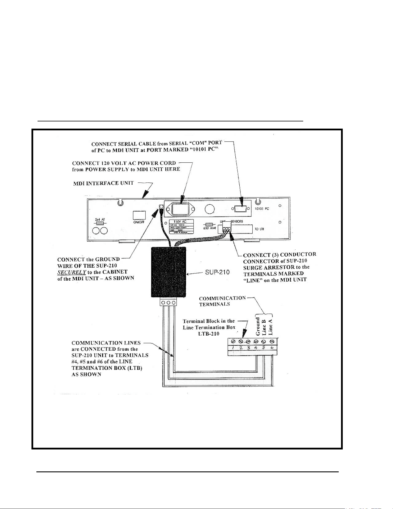
GT27141D Page 149 November 2003
INSTALLATION DETAILS FOR
MDI INTERFACE UNIT AND LINE
TERMINATION BOX (LTB).
Wiring of SUP-210 Surge Arrestor at MDI Interface Unit:
WIRING OF SUP-210 SURGE ARRESTOR
FIGURE: A-1
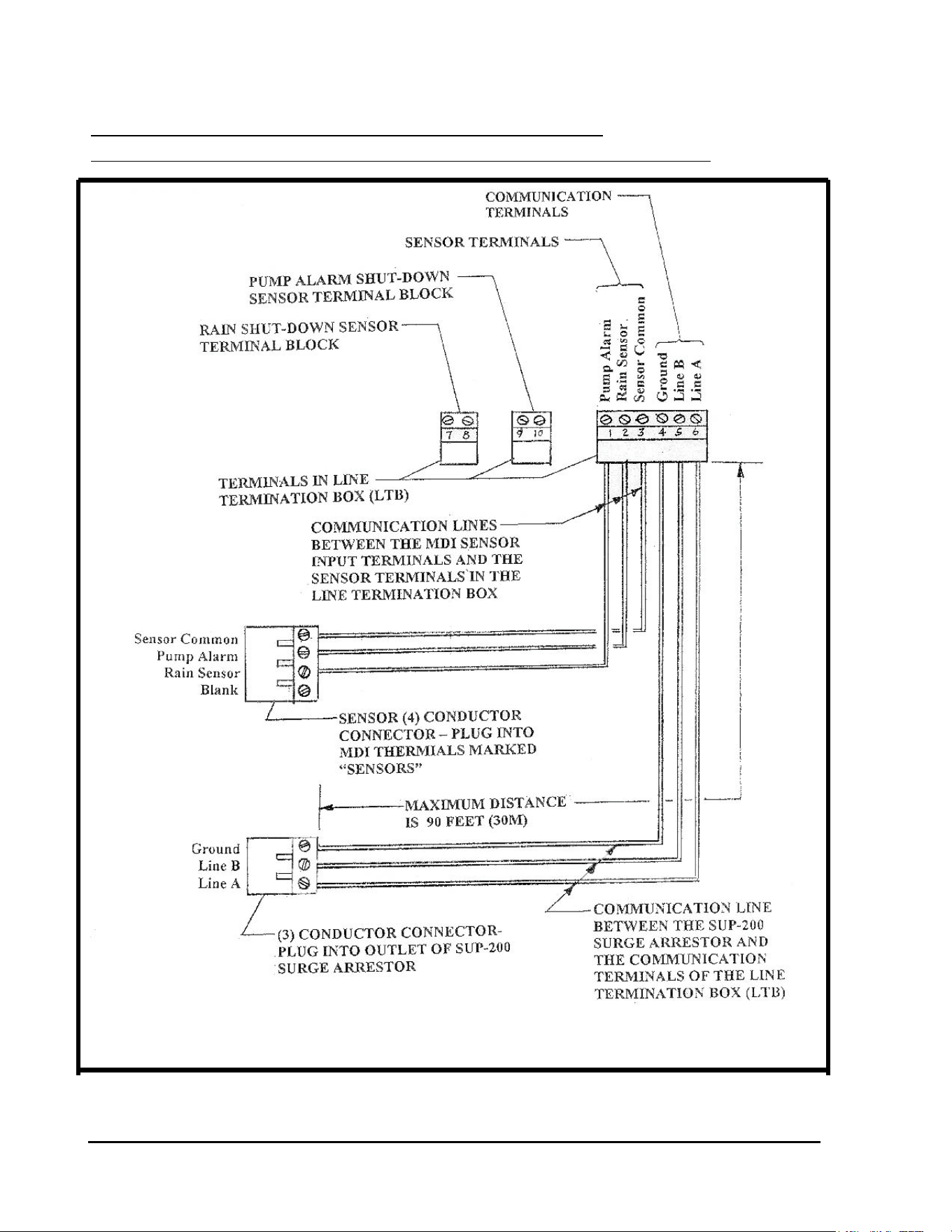
GT27141C Page 150 November 2003
Communication and Sensor Wiring Between
DI Interface unit and Line Termination Box (LTB-210):
COMMUNICATION & SENSOR WIRING DETAIL
FIGURE: A-2
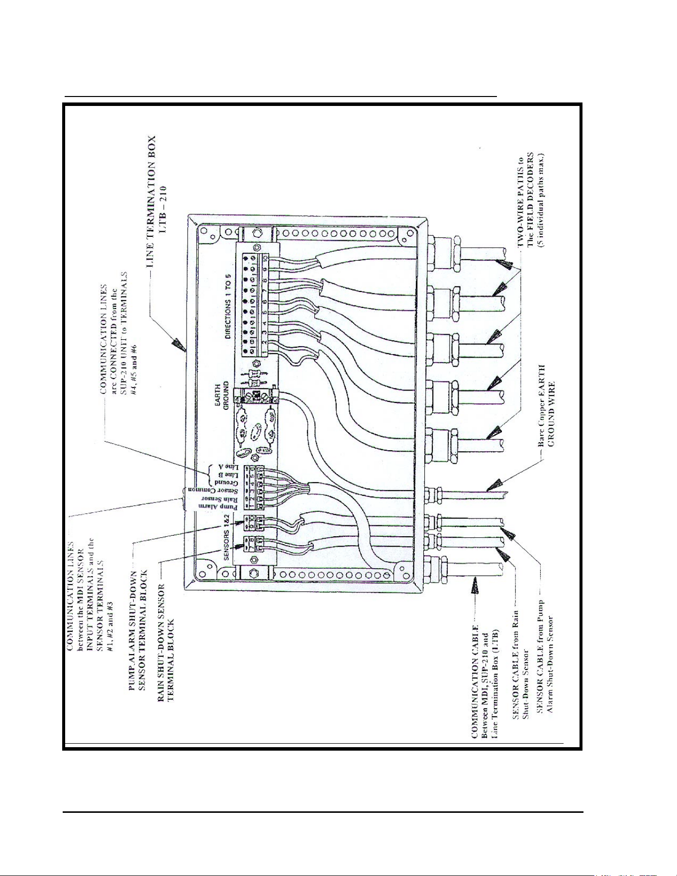
GT27141D Page 151 November 2003
Wiring Detail at the Line Termination Box (LTB-210):
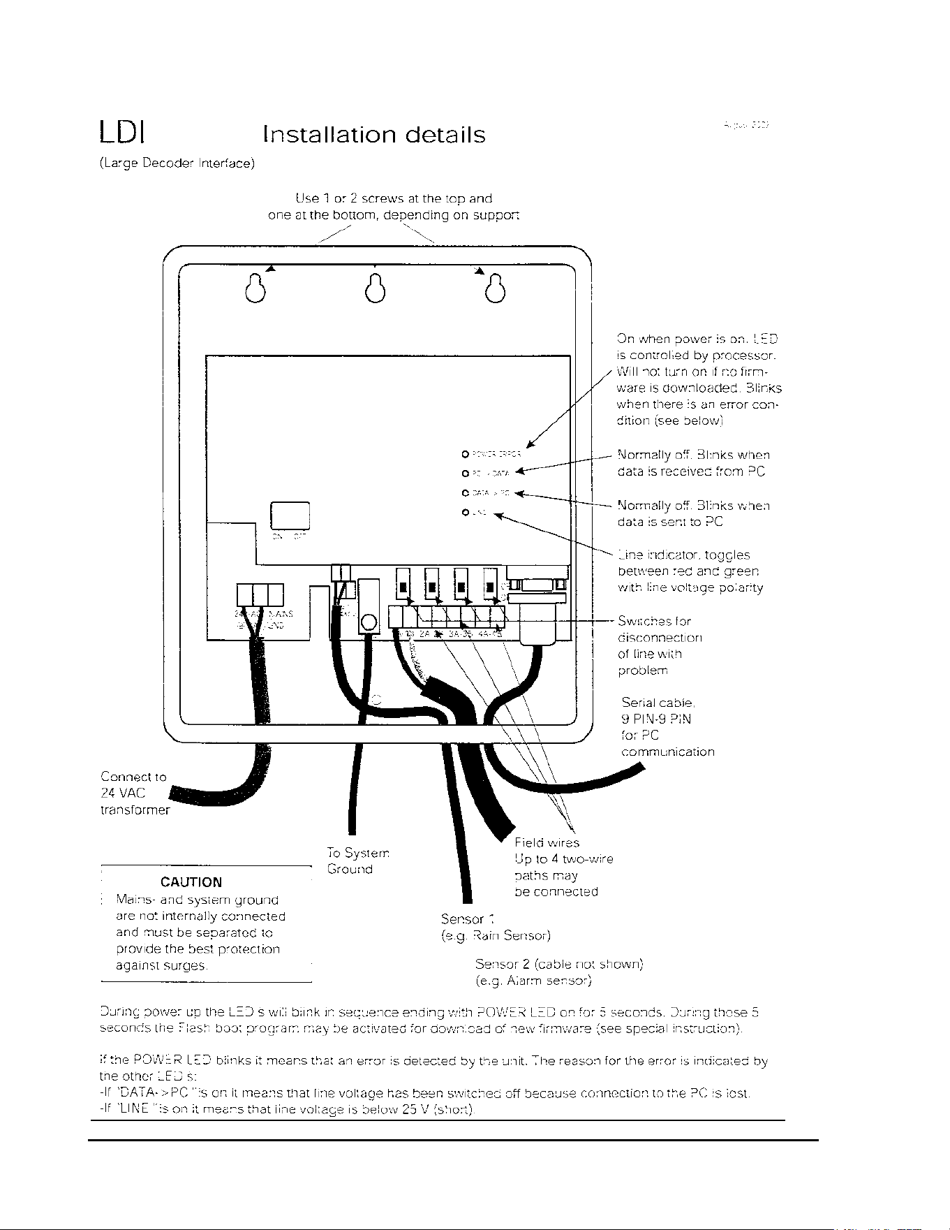
GT27141C Page 152 November 2003
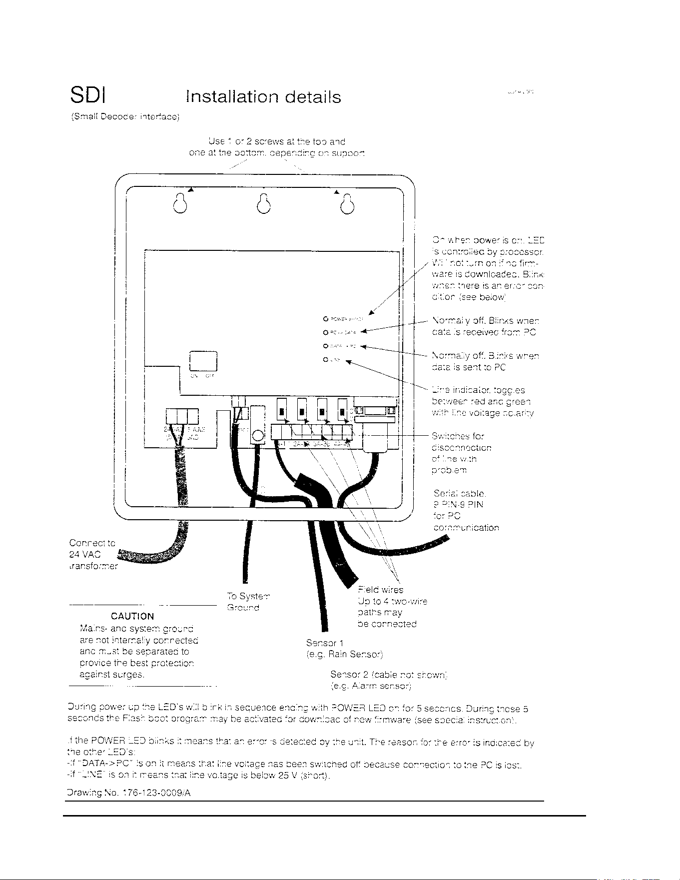
GT27141D Page 153 November 2003
