
Technical Support and E-Warranty Certificate www.vevor.com/support
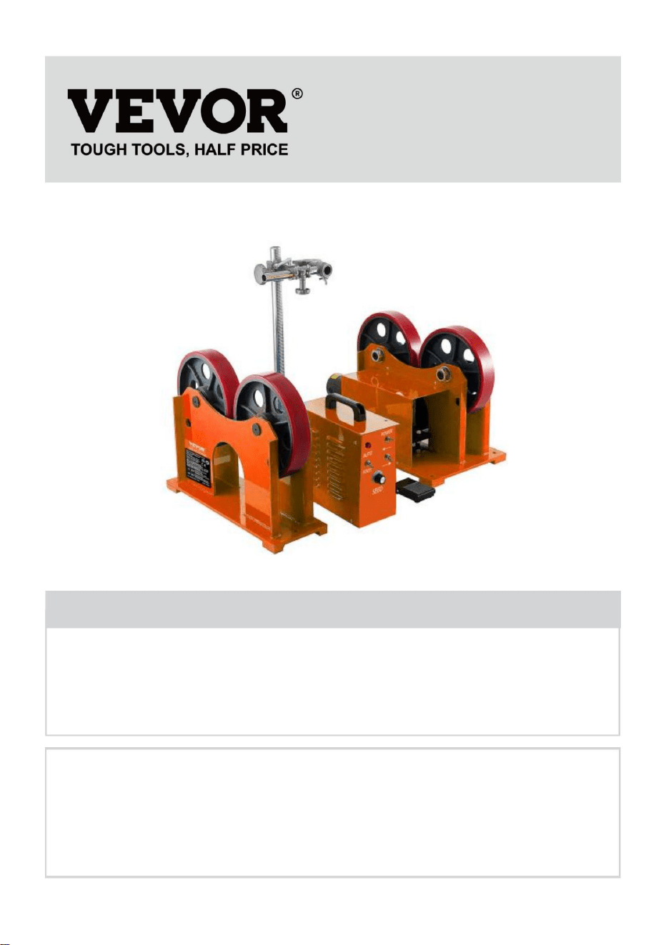
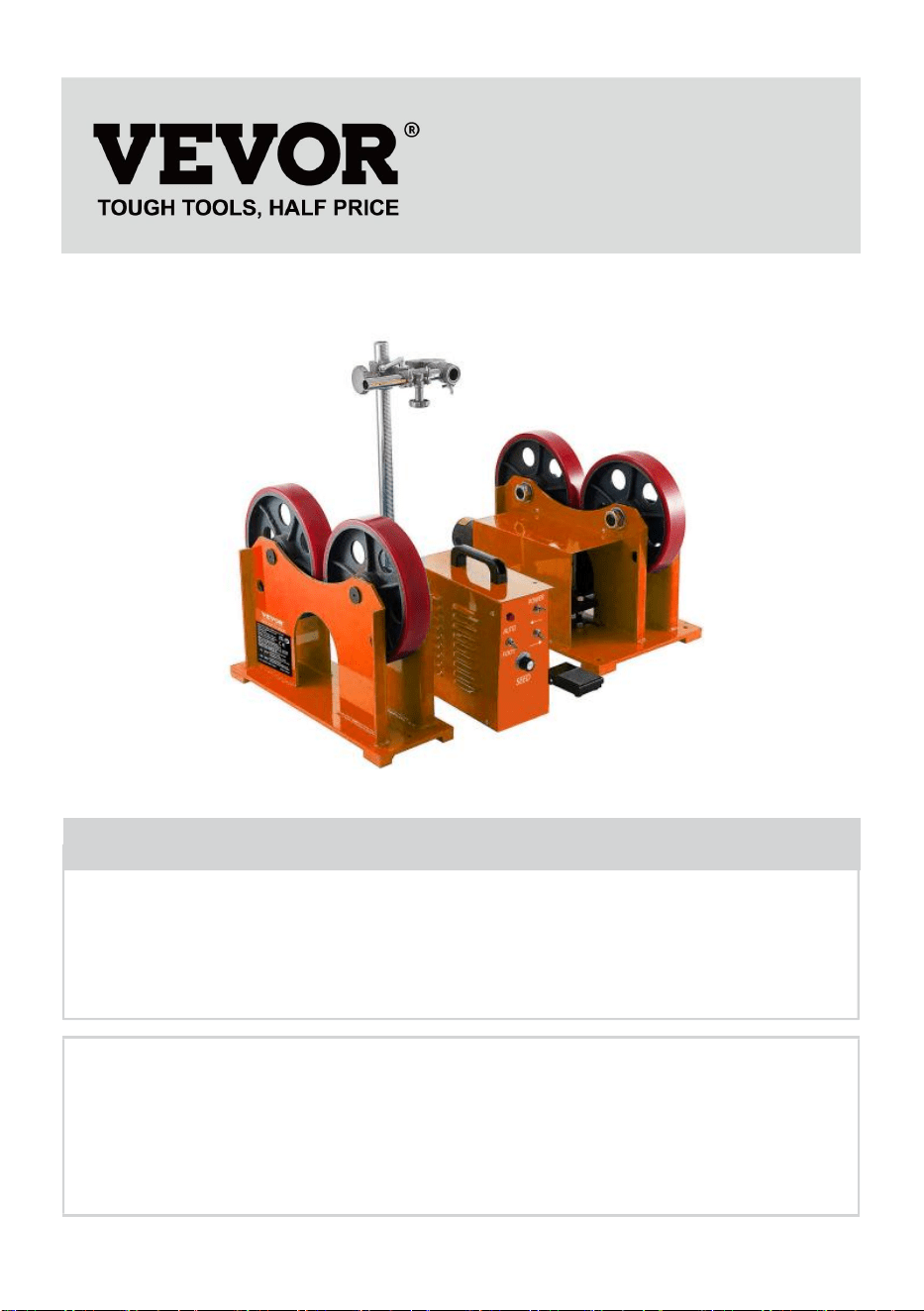
WELDING POSITIONER
MODEL: HDTR-1000
We continue to be committed to provide you tools with competitive price.
"Save Half", "Half Price" or any other similar expressions used by us only
represents an estimate of savings you might benefit from buying certain
tools with us compared to the major top brands and does not necessarily
mean to cover all categories of tools offered by us. You are kindly reminded
to verify carefully when you are placing an order with us if you are actually
saving half in comparison with the top major brands.

- 1 -
MODEL:HDTR-1000
Have product questions? Need technical support? Please feel free to
contact us:
Technical Support and E-Warranty Certificate
www.vevor.com/support
NEED HELP? CONTACT US!
This is the original instruction, please read all manual instructions
carefully before operating. VEVOR reserves a clear interpretation of our
user manual. The appearance of the product shall be subject to the
product you received. Please forgive us that we won't inform you again if
there are any technology or software updates on our product.
WELDING
POSITIONER

- 2 -
Warning-To reduce the risk of injury, user must read
instructions manual carefully.
CORRECT DISPOSAL
This product is subject to the provision of European Directive
2012/19/EC. The symbol showing a wheelie bin crossed
through indicates that the product requires separate refuse
collection in the European Union. This applies to the product
and all accessories marked with this symbol. Products marked
as such may not be discarded with normal domestic waste, but
must be taken to a collection point for recycling electrical and
electronic devices
IMPORTANT SAFEGUARDS
WARNING : A procedure, which, if not properly followed, may cause
injury to the operator or others in the operating area.
Equipment Identification
The identification number specification or model, and serial number of this unit
usually appears on a nameplate attached to the control panel, record these
numbers for future reference.
Receipt of Equipment
When you receive the equipment, check it against the shipping documents, Make
sure it is complete and inspect the equipment for possible damage during shipping,
if there is any damage, notify the carrier immediately to file a claim.
Furnish complete information concerning damage claims or mistake(s) in shipment
to Machinery Co.,Ltd’s Include the equipment identification number along with a
description of the parts in question.
Move the equipment to the installation site before uncrating the unit. Use care to
avoid damaging the equipment when using bars, hammers, etc.to uncrate the unit.

- 3 -
General safety rules:
Before removing the body of the product, pull out the wire first.
The operator must be qualified accordingly.
The operation can only be controlled by qualified technicians.
The compressed air power must be cut off and turned off before the maintenance
operation is carried out.
Electrodes, electrode arms and other secondary conductors can reach very high
temperatures and stay high for a long time after stopping the machine. Pay
attention to scald.
Preventive maintenance is necessary on a regular basis.
Power Connection:
1. Check that the device must be connected to the ground coupler and to the
ground.It is in good condition.
2. Check if the workbench is connected to the ground connector.
3. Ensure that the operator does not have any contact, protection or wet clothing
with the metal parts to be welded.
4. Avoid contact with welded parts.
5. Do not spot weld in very wet places or on wet floors.
6. Do not weld with worn cables. Check that the isolation belt does not have a
default cable or that the connection is loose.
7. Please turn off the device before replacing the electrode.
8. Please disconnect the equipment directly before it is controlled or repaired.
Protection of Eyes and Body:
1. During welding, wear leather gloves, welded apron, safety shoes, welding
protective clothing, arc filtering and radiation projective helmet or glasses.The
operator must protect his eyes during rubbing and hammering.
2. Don't wear rings, watches or jewelry. It can cause burns.
3. All protective board must be in good condition and in proper position. In the
absence of eye protection, do not look at the welding arc. Protect the environment
near the product from projection and reflection.

- 4 -
Welding Fume:
Welding operations can lead to the emission of toxic smoke and harmful metal
dust. The equipment should be installed in covered areas with smoke inhalers.
Operators must wear smoke masks. Welding materials must be cleaned.
Pay Attention to Fire:
1. Check whether sparks cause fires, especially in the vicinity of flammable
materials.
2. Check that the fire extinguisher is not far from the operator.
3. Place the equipment where there are pneumatic devices.
4. Do not weld on a container with flammable and lubricant, even if it is empty.
5. Do not weld in an atmosphere filled with flammable gas or fuel vapor.
Electromagnetic Compatibility:
Near the welding site, check:
● There are no other power cords, control cables, telephone lines, radio or
television reception equipment, watches, mobile phones, magnetic cards,
computers or any other electronic device.
● No active medical devices (pacemakers, acoustic prostheses) were used
around (at least 3 meters).
FCC Information:
● CAUTION: Changes or modifications not expressly approved by the party
responsible for compliance could void the user's authority to operate the
equipment!
This device complies with Part 15 of the FCC Rules. Operation is subject to the
following two conditions:
1) This product may cause harmful interference.
2) This product must accept any interference received, including interference that
may cause undesired operation.
● WARNING: Changes or modifications to this product not expressly approved by

- 5 -
the party.responsible for compliance could void the user's authority to operate the
product.
● Note: This product has been tested and found to comply with the limits for a
Class B digital device pursuant to Part 15 of the FCC Rules, These limits are
designed to provide reasonable protection against harmful interference in a
residential installation.
This product generates, uses and can radiate radio frequency energy, and if not
installed and used in accordance with the instructions, may cause harmful
interference to radio communications. However, there is no guarantee that
interference will not occur in a particular installation. If this product does cause
harmful interference to radio or television reception,which can be determined by
turning the product off and on, the user is encouraged to try to correct the
interference by one or more of the following measures.
● Reorient or relocate the receiving antenna.
● Increase the distance between the product and receiver.
● Connect the product to an outlet on a circuit different from that to which the
receiver is connected.
● Consult the dealer or an experienced radio/TV technician for assistance.
SPECIFICATION
Model
HDTR-1000
HDTR-1000
Input Power
AC120V/60Hz
AC230V/50Hz
Load Capacity
1000kg
1000kg
Speed Range
80~1600mm/min
80~1600mm/min
Diameter Range
Ф25~Ф800mm
Ф25~Ф800mm
Drive Motor
600W
600W
Roller Type
50mm(W)×Ф250mm
50mm(W)×Ф250mm
Roller material
Polyurethane
Polyurethane
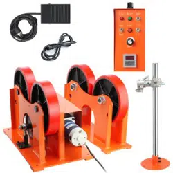
Accessories
Power cord *1
foot switch *1,
control box *1
connecting aviation plug *1
Power cord *1
foot switch *1,
control box *1
connecting aviation plug *1

- 6 -
set of gun holder (with rod)
*1,
gun holder holder *1,
manual *1,
set of gun holder (with rod)
*1,
gun holder holder *1,
manual *1,
Note: The diameter of the outer mounting hole of the roller is 200-1400mm;
The vertical rod stroke of welding torch bracket is 600mm, the horizontal rod
stroke is 180mm
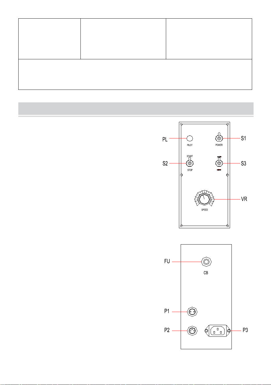
CONTROL PANEL
HDTR-1000:
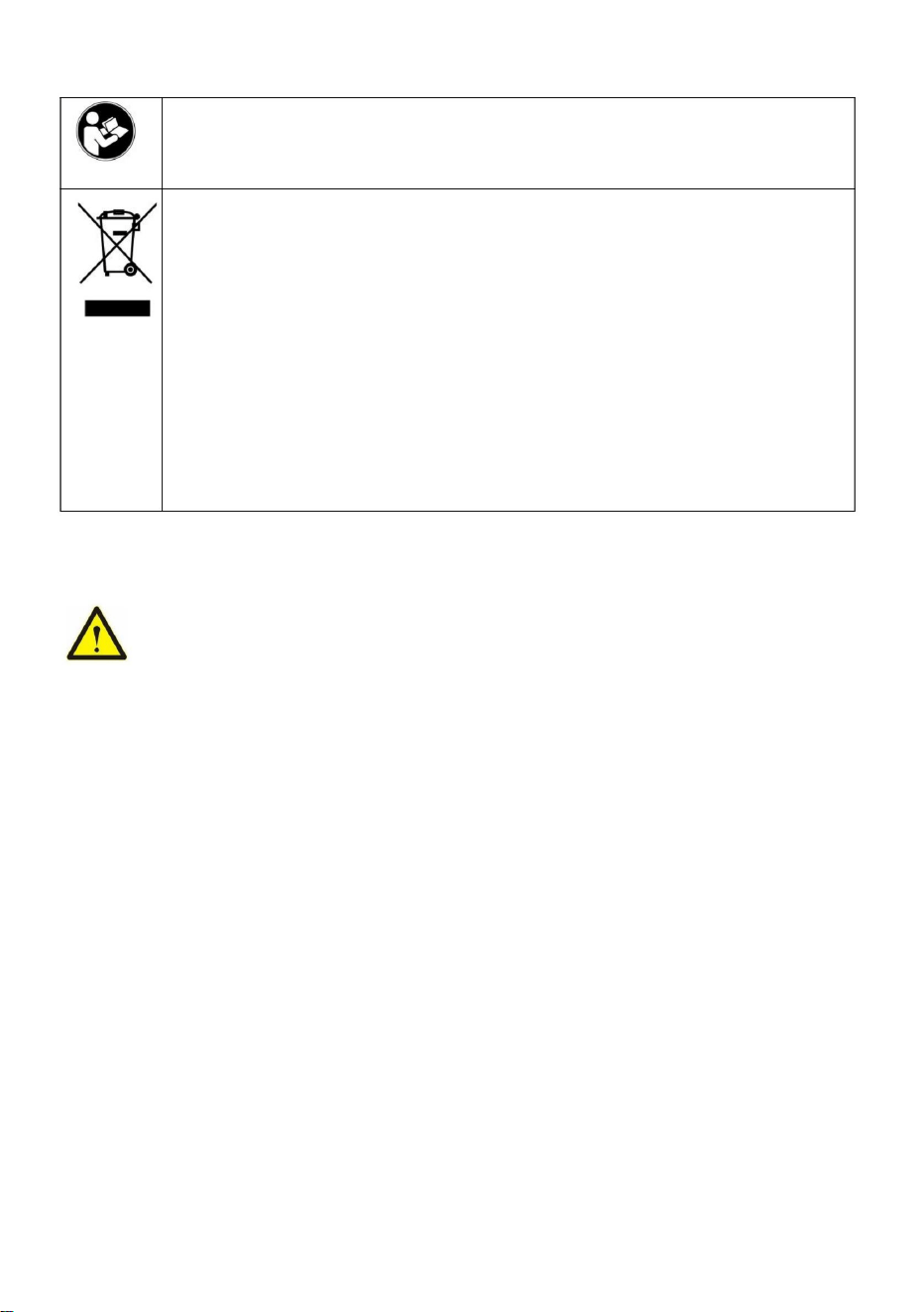
1. Front Panel
PL: Power Pilot
S1: Power ON/OFF Switch
S2: Start/Stop Switch(When use FOOT
switch,the S2 should on STOP.)
S3: Forward/Reverse Switch
VR: Speed Adjustment
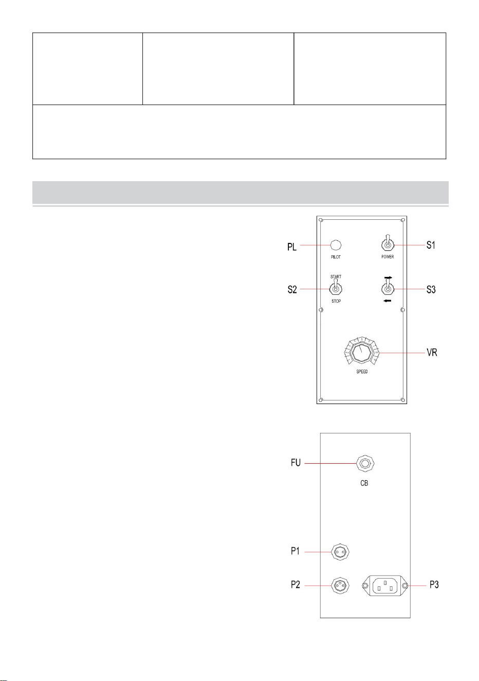
2. Real Panel
FU: Fuse (CB)
P1: Motor Connector (2Pin)
P2: Foot Switch Connector (3Pin)
P3: Input Power Connector

- 7 -
TROUBLE SHOOTING GUIDE
NO.
SYMPTOM
POSSIBLE CAUSE
REMEDY
1
Power pilot
does not lit
1. Power fuse is burnt.
2. LED burnt.
3. Power switch is burnt.
4. No power input.
1. Replace a new fuse.
2. Replace LED.
3. Replace switch.
4. Check the switch or
replace.
2
Speed
Adjustment
no Motion.
1. Damaged
potentiometer.
2. Motor control PCB no
output.
1. Check if potentiometer
is 10KΩ, otherwise replace.
2. Replace a new motor
control PCB.
3
Foot switch
no motion
Foot switch is damaged.
Check the foot switch or
replace.
4
Forward/Re
verse no
output
Forward/Reverse switch is
damaged.
Check the switch or
replace.
5
Motor no
motion
1. Motor has power input
but no motion.
2. Motor control PCB has
no power input
3. Motor control PCB is
damaged.
1. Replace a new motor.
2. Check the transformer or
replace.
3. Replace control PCB.
6
Motor no
motion
1. Motor has power input
but no motion.
2. AC driver has no power
input
3. AC driver is damaged.
1. Replace a new motor.
2. Check the transformer or
replace.
3. Replace AC driver
Made In China


POSTESDESOUDAGE
MODÈLE:HDTR1000
Assistancetechniqueetcertificatdegarantieélectroniquewww.vevor.com/support
Nouscontinuonsànousengageràvousfournirdesoutilsàdesprixcompétitifs.
"Économisezlamoitié","Moitiéprix"outouteautreexpressionsimilairequenous
utilisonsnereprésentequ'uneestimationdeséconomiesdontvouspourriezbénéficier
enachetantcertainsoutilscheznousparrapportauxgrandesmarquesetnesignifie
pasnécessairementcouvrirtouteslescatégoriesd'outilsproposés.parnous.Nousvous
rappelonsdevérifierattentivementlorsquevouspassezunecommandecheznoussi
vouséconomisezréellementlamoitiéparrapportauxgrandesmarques.
Machine Translated by Google
Ils'agitdesinstructionsoriginales,veuillezlireattentivementtouteslesinstructions
dumanuelavantdel'utiliser.VEVORseréserveuneinterprétationclairedenotremanuel
d’utilisation.L'apparenceduproduitdépendduproduitquevousavezreçu.Veuillez
nouspardonnerquenousnevousinformeronspluss'ilyadesmisesàjourtechnologiques
oulogiciellessurnotreproduit.
Modèle:HDTR1000
Vousavezdesquestionssurlesproduits?Besoind'uneassistancetechnique?
N'hésitezpas
ànouscontacter:Supporttechniqueetcertificatdegarantie
électroniquewww.vevor.com/support
BESOIND'AIDE?CONTACTEZNOUS!
POSITIONNEUR
SOUDAGE
1
Machine Translated by Google
Identificationdel'équipement
GARANTIESIMPORTANTES
Réceptiondumatériel
Fournirdesinformationscomplètesconcernantlesréclamationspourdommagesouleserreursd'expédition
blessuresàl'opérateurouàd'autrespersonnessetrouvantdanslazoned'opération.
encasdedommage,informezenimmédiatementletransporteurpourdéposeruneréclamation.
Uneprocédurequi,siellen'estpascorrectementsuivie,peutentraîner
assurezvousqu'ilestcompletetinspectezl'équipementpourdécelerd'éventuelsdommagespendantletransport,
AVERTISSEMENT
Lorsquevousrecevezl'équipement,vérifiezleparrapportauxdocumentsd'expédition,faites
numérospourréférencefuture.
évitezd'endommagerl'équipementlorsquevousutilisezdesbarres,desmarteaux,etc.pourdéballerl'appareil.
descriptiondespiècesenquestion.
Déplacezl'équipementverslesited'installationavantdedéballerl'unité.Faitesattentionà
apparaîtgénéralementsuruneplaquesignalétiquefixéeaupanneaudecommande,enregistrezles
àMachineryCo.,Ltd.Incluezlenumérod'identificationdel'équipementainsiqu'un
Lenumérod'identificationoulemodèleetlenumérodesériedecetappareil
ÉLIMINATIONCORRECTE
collectiondansl’Unioneuropéenne.Cecis'appliqueauproduit
ettouslesaccessoiresmarquésdecesymbole.Produitsmarqués
àtraversindiquequeleproduitnécessitedesdéchetsséparés
attentivementlemanueld’instructions.
2012/19/CE.Lesymbolereprésentantunepoubellebarrée
appareilsélectroniques
doiventêtredéposésdansunpointdecollectepourlerecyclagedesappareilsélectriqueset
AvertissementPourréduirelerisquedeblessure,l'utilisateurdoitlire
Ceproduitestsoumisauxdispositionsdeladirectiveeuropéenne
entantquetel,ilnedoitpasêtrejetéaveclesorduresménagèresnormales,mais
2
Machine Translated by Google

Connexionélectrique:
Protectiondesyeuxetducorps:
Règlesgénéralesdesécurité:
5.Nesoudezpasparpointsdansdesendroitstrèshumidesousurdessolsmouillés.
aveclespiècesmétalliquesàsouder.
températuresetrestentélevéespendantlongtempsaprèsl'arrêtdelamachine.Payer
Lesélectrodes,brasd'électrodesetautresconducteurssecondairespeuventatteindredesvaleurstrèsélevées.
3.Assurezvousquel'opérateurn'aaucuncontact,protectionouvêtementsmouillés
l'opérationesteffectuée.
1.Pendantlesoudage,portezdesgantsencuir,untabliersoudé,deschaussuresdesécurité,desgantsdesoudage.
vêtementsdeprotection,filtraged'arcetcasqueoulunettesprojectifsderayonnement.
L'alimentationenaircomprimédoitêtrecoupéeetéteinteavantlamaintenance
2.Vérifiezsil'établiestconnectéauconnecteurdeterre.
l'opérateurdoitprotégersesyeuxlorsdufrottementetdumartelage.
L'opérationnepeutêtrecontrôléequepardestechniciensqualifiés.
terrain.Ilestenbonétat.
8.Veuillezdéconnecterl'équipementdirectementavantdelecontrôleroudeleréparer.
L'opérateurdoitêtrequalifiéenconséquence.
àproximitéduproduitcontrelaprojectionetlaréflexion.
1.Vérifiezquel'appareildoitêtreconnectéaucoupleurdeterreetau
7.Veuillezéteindrel'appareilavantderemplacerl'électrode.
câblepardéfautouquelaconnexionestlâche.
Avantderetirerlecorpsduproduit,retirezd'abordlefil.
absencedeprotectionoculaire,nepasregarderl’arcdesoudage.Protégerl'environnement
2.Neportezpasdebagues,demontresoudebijoux.Celapeutprovoquerdesbrûlures.
Unentretienpréventifestnécessairerégulièrement.
6.Nesoudezpasavecdescâblesusés.Vérifiezquelaceintured'isolationnecomportepasde
3.Touslespanneauxdeprotectiondoiventêtreenbonétatetcorrectementpositionnés.Dansle
4.Éviteztoutcontactaveclespiècessoudées.
attentionauxbrûlures.
3
Machine Translated by Google

Compatibilitéélectromagnétique:
Aproximitéduchantierdesoudure,vérifier:
InformationsFCC:
Faitesattentionaufeu:
Fuméesdesoudage:
•ATTENTION:Changementsoumodificationsnonexpressémentapprouvésparlapartie
matériaux.
2.Vérifiezquel'extincteurn'estpasloindel'opérateur.
autour(aumoins3mètres).
équipementsderéceptiondetélévision,montres,téléphonesportables,cartesmagnétiques,ordinateurs
outoutautreappareilélectronique.•Aucundispositif
médicalactif(pacemakers,prothèsesacoustiques)n'aétéutilisé
1.Vérifiezsilesétincellesprovoquentdesincendies,enparticulieràproximitédeproduitsinflammables.
2)Ceproduitdoitacceptertouteinterférencereçue,ycomprislesinterférencesqui
peutprovoquerunfonctionnementindésirable.
•AVERTISSEMENT:changementsoumodificationsapportésàceproduitnonexpressémentapprouvéspar
•Iln'yaaucunautrecordond'alimentation,câbledecommande,lignetéléphonique,radioou
1)Ceproduitpeutprovoquerdesinterférencesnuisibles.
Lesopérateursdoiventporterdesmasquesantifumée.Lesmatériauxdesoudagedoiventêtrenettoyés.
suivantdeuxconditions:
poussière.L'équipementdoitêtreinstallédansdeszonescouvertesavecdesinhalateursdefumée.
Cetappareilestconformeàlapartie15desrèglesFCC.L'exploitationestsoumiseaux
équipement!
Lesopérationsdesoudagepeuvententraînerl'émissiondefuméestoxiquesetdemétauxnocifs
5.Nesoudezpasdansuneatmosphèrerempliedegazinflammablesoudevapeursdecarburant.
4.Nesoudezpassurunrécipientcontenantdesproduitsinflammablesetdulubrifiant,mêmes'ilestvide.
responsabledelaconformitépourraitannulerledroitdel'utilisateuràutiliserle
3.Placezl'équipementlàoùsetrouventdesdispositifspneumatiques.
4
Machine Translated by Google

Lapuissanced'entrée
Polyuréthane
F25F800mm
installéetutiliséconformémentauxinstructions,peutcauserdesdommages
Modèle
Matériaudurouleau
Accessoires
600W
•Consultezlerevendeurouuntechnicienradio/TVexpérimentépourobtenirdel'aide.
installationrésidentielle.
1000kg
interrupteuraupied*1,
boîtierdecommande*1
Cordond'alimentation*1
GammedediamètreФ25Ф800mm
interférenceparuneouplusieursdesmesuressuivantes.•Réorientezou
déplacezl'antennederéception.•Augmentezladistance
entreleproduitetlerécepteur.•Connectezleproduitàuneprisesuruncircuit
différentdeceluiauquelle
AppareilnumériquedeclasseBconformémentàlapartie15desrèglesFCC.Ceslimitessont
HDTR1000
Polyuréthane
50mm(L)×F250mm
600W
Capacitédechargement
interférencesnuisiblesàlaréceptionradiooutélévision,quipeuventêtredéterminéespar
lapartieresponsabledelaconformitépourraitannulerlepouvoirdel'utilisateurd'utiliserle
1000kg
HDTR1000
interrupteuraupied*1,
boîtierdecommande*1
80~1600mm/min
Ceproduitgénère,utiliseetpeutémettredel'énergieradiofréquence,etsinon
interférenceaveclescommunicationsradio.Cependant,riennegarantitque
Typederouleau
connexiondelaprised'aviation*1
Cordond'alimentation*1
AC230V/50Hz
conçupourfourniruneprotectionraisonnablecontrelesinterférencesnuisiblesdansun
lerécepteurestconnecté.
Moteurd'entraînement
Plagedevitesse
80~1600mm/min
produit.•
Remarque:Ceproduitaététestéetdéclaréconformeauxlimitesd'un
enéteignantetenallumantleproduit,l'utilisateurestencouragéàessayerdecorrigerle
50mm(L)×F250mm
AC120V/60Hz
aucuneinterférenceneseproduiradansuneinstallationparticulière.Siceproduitprovoque
connexiondelaprised'aviation*1
SPÉCIFICATION
5
Machine Translated by Google
lacourseestde180mm
Lacourseverticaledelatigedusupportdetorchedesoudageestde600mm,latigehorizontale
jeudeportepistolet(avectige)
*1,
portepistolet*1,manuel
*1,
Remarque:Lediamètredutroudemontageextérieurdurouleauestde200à1400mm
jeudeportepistolet(avectige)
*1,
portepistolet*1,manuel
*1,
P2:connecteurdecommutateuraupied(3broches)
HDTR1000:
1.Panneauavant
interrupteur,leS2devraitêtresurSTOP.)
2.Panneauréel
PANNEAUDECONTRÔLE
FU:Fusible(CB)
S2:interrupteurmarche/arrêt(lorsdel'utilisationdupied
VR:ajustementdelavitesse
S1:interrupteurmarche/arrêt
P3:connecteurd'alimentationd'entrée
S3:commutateuravant/arrière
P1:connecteurmoteur(2broches)
PL:Pilotedepuissance
6
Machine Translated by Google

remplacer.
Lecommutateuravant/arrièreest
potentiomètre.
2.LepiloteACn’estpasalimenté
3.LePCBdecommandedumoteurest
Interrupteuraupied
nes'allumepas
4
Vitesse
REMÈDE
1.Remplacezunnouveaumoteur.
1.Lefusibled’alimentationestgrillé.
Moteurnon
4.Vérifiezl'interrupteurou
remplacer.
1.Vérifiezsilepotentiomètre
Moteurnon
maispasdemouvement.
sortir.
Lapédaledecommandeestendommagée.
3.L’interrupteurd’alimentationestgrillé.
endommagé.
3.Remplacezlacartedecommande.
Vérifiezl'interrupteurou
2.Vérifiezletransformateurou
voirnon
1.Remplacezunnouveaufusible.
Ajustement
saisir
mouvement
3
remplacer.
2.LePCBdecommandedumoteura
pasdemouvement.
Pilotedepuissance
mouvement
1.Lemoteurauneentréedepuissance
estde10KΩ,sinonremplacezle.
NON.SYMPTÔME
endommagé.
3.LepiloteCAestendommagé.
1.Remplacezunnouveaumoteur.
pasdemouvement
4.Aucuneentréed’énergie.
remplacer.
sortir
2
2.RemplacezlaLED.
2.LaLEDestgrillée.
cartedecontrôle.
Transférer/Re
1.Endommagé
remplacer.
2.Remplacezunnouveaumoteur
CAUSEPOSSIBLE
5
6
pasd'entréed'alimentation
2.Vérifiezletransformateurou
Vérifiezlapédaledecommandeou
1
maispasdemouvement.
3.RemplacezlepiloteAC
2.PCBdecommandedumoteurnon
3.Remplacezl'interrupteur.
1.Lemoteurauneentréedepuissance
FabriquéenChine
GUIDEDEDÉPANNAGE
7
Machine Translated by Google


Technical Support and E-Warranty Certificate www.vevor.com/support
WELDING POSITIONER
MODEL: HDTR-1000
We continue to be committed to provide you tools with competitive price.
"Save Half", "Half Price" or any other similar expressions used by us only
represents an estimate of savings you might benefit from buying certain
tools with us compared to the major top brands and does not necessarily
mean to cover all categories of tools offered by us. You are kindly reminded
to verify carefully when you are placing an order with us if you are actually
saving half in comparison with the top major brands.

- 1 -
MODEL:HDTR-1000
Have product questions? Need technical support? Please feel free to
contact us:
Technical Support and E-Warranty Certificate
www.vevor.com/support
NEED HELP? CONTACT US!
This is the original instruction, please read all manual instructions
carefully before operating. VEVOR reserves a clear interpretation of our
user manual. The appearance of the product shall be subject to the
product you received. Please forgive us that we won't inform you again if
there are any technology or software updates on our product.
WELDING
POSITIONER

- 2 -
Warning-To reduce the risk of injury, user must read
instructions manual carefully.
CORRECT DISPOSAL
This product is subject to the provision of European Directive
2012/19/EC. The symbol showing a wheelie bin crossed
through indicates that the product requires separate refuse
collection in the European Union. This applies to the product
and all accessories marked with this symbol. Products marked
as such may not be discarded with normal domestic waste, but
must be taken to a collection point for recycling electrical and
electronic devices
IMPORTANT SAFEGUARDS
WARNING : A procedure, which, if not properly followed, may cause
injury to the operator or others in the operating area.
Equipment Identification
The identification number specification or model, and serial number of this unit
usually appears on a nameplate attached to the control panel, record these
numbers for future reference.
Receipt of Equipment
When you receive the equipment, check it against the shipping documents, Make
sure it is complete and inspect the equipment for possible damage during shipping,
if there is any damage, notify the carrier immediately to file a claim.
Furnish complete information concerning damage claims or mistake(s) in shipment
to Machinery Co.,Ltd’s Include the equipment identification number along with a
description of the parts in question.
Move the equipment to the installation site before uncrating the unit. Use care to
avoid damaging the equipment when using bars, hammers, etc.to uncrate the unit.

- 3 -
General safety rules:
Before removing the body of the product, pull out the wire first.
The operator must be qualified accordingly.
The operation can only be controlled by qualified technicians.
The compressed air power must be cut off and turned off before the maintenance
operation is carried out.
Electrodes, electrode arms and other secondary conductors can reach very high
temperatures and stay high for a long time after stopping the machine. Pay
attention to scald.
Preventive maintenance is necessary on a regular basis.
Power Connection:
1. Check that the device must be connected to the ground coupler and to the
ground.It is in good condition.
2. Check if the workbench is connected to the ground connector.
3. Ensure that the operator does not have any contact, protection or wet clothing
with the metal parts to be welded.
4. Avoid contact with welded parts.
5. Do not spot weld in very wet places or on wet floors.
6. Do not weld with worn cables. Check that the isolation belt does not have a
default cable or that the connection is loose.
7. Please turn off the device before replacing the electrode.
8. Please disconnect the equipment directly before it is controlled or repaired.
Protection of Eyes and Body:
1. During welding, wear leather gloves, welded apron, safety shoes, welding
protective clothing, arc filtering and radiation projective helmet or glasses.The
operator must protect his eyes during rubbing and hammering.
2. Don't wear rings, watches or jewelry. It can cause burns.
3. All protective board must be in good condition and in proper position. In the
absence of eye protection, do not look at the welding arc. Protect the environment
near the product from projection and reflection.

- 4 -
Welding Fume:
Welding operations can lead to the emission of toxic smoke and harmful metal
dust. The equipment should be installed in covered areas with smoke inhalers.
Operators must wear smoke masks. Welding materials must be cleaned.
Pay Attention to Fire:
1. Check whether sparks cause fires, especially in the vicinity of flammable
materials.
2. Check that the fire extinguisher is not far from the operator.
3. Place the equipment where there are pneumatic devices.
4. Do not weld on a container with flammable and lubricant, even if it is empty.
5. Do not weld in an atmosphere filled with flammable gas or fuel vapor.
Electromagnetic Compatibility:
Near the welding site, check:
● There are no other power cords, control cables, telephone lines, radio or
television reception equipment, watches, mobile phones, magnetic cards,
computers or any other electronic device.
● No active medical devices (pacemakers, acoustic prostheses) were used
around (at least 3 meters).
FCC Information:
● CAUTION: Changes or modifications not expressly approved by the party
responsible for compliance could void the user's authority to operate the
equipment!
This device complies with Part 15 of the FCC Rules. Operation is subject to the
following two conditions:
1) This product may cause harmful interference.
2) This product must accept any interference received, including interference that
may cause undesired operation.
● WARNING: Changes or modifications to this product not expressly approved by

- 5 -
the party.responsible for compliance could void the user's authority to operate the
product.
● Note: This product has been tested and found to comply with the limits for a
Class B digital device pursuant to Part 15 of the FCC Rules, These limits are
designed to provide reasonable protection against harmful interference in a
residential installation.
This product generates, uses and can radiate radio frequency energy, and if not
installed and used in accordance with the instructions, may cause harmful
interference to radio communications. However, there is no guarantee that
interference will not occur in a particular installation. If this product does cause
harmful interference to radio or television reception,which can be determined by
turning the product off and on, the user is encouraged to try to correct the
interference by one or more of the following measures.
● Reorient or relocate the receiving antenna.
● Increase the distance between the product and receiver.
● Connect the product to an outlet on a circuit different from that to which the
receiver is connected.
● Consult the dealer or an experienced radio/TV technician for assistance.
SPECIFICATION
Model
HDTR-1000
HDTR-1000
Input Power
AC120V/60Hz
AC230V/50Hz
Load Capacity
1000kg
1000kg
Speed Range
80~1600mm/min
80~1600mm/min
Diameter Range
Ф25~Ф800mm
Ф25~Ф800mm
Drive Motor
600W
600W
Roller Type
50mm(W)×Ф250mm
50mm(W)×Ф250mm
Roller material
Polyurethane
Polyurethane
Accessories
Power cord *1
foot switch *1,
control box *1
connecting aviation plug *1
Power cord *1
foot switch *1,
control box *1
connecting aviation plug *1

- 6 -
set of gun holder (with rod)
*1,
gun holder holder *1,
manual *1,
set of gun holder (with rod)
*1,
gun holder holder *1,
manual *1,
Note: The diameter of the outer mounting hole of the roller is 200-1400mm;
The vertical rod stroke of welding torch bracket is 600mm, the horizontal rod
stroke is 180mm
CONTROL PANEL
HDTR-1000:
1. Front Panel
PL: Power Pilot
S1: Power ON/OFF Switch
S2: Start/Stop Switch(When use FOOT
switch,the S2 should on STOP.)
S3: Forward/Reverse Switch
VR: Speed Adjustment
2. Real Panel
FU: Fuse (CB)
P1: Motor Connector (2Pin)
P2: Foot Switch Connector (3Pin)
P3: Input Power Connector

- 7 -
TROUBLE SHOOTING GUIDE
NO.
SYMPTOM
POSSIBLE CAUSE
REMEDY
1
Power pilot
does not lit
1. Power fuse is burnt.
2. LED burnt.
3. Power switch is burnt.
4. No power input.
1. Replace a new fuse.
2. Replace LED.
3. Replace switch.
4. Check the switch or
replace.
2
Speed
Adjustment
no Motion.
1. Damaged
potentiometer.
2. Motor control PCB no
output.
1. Check if potentiometer
is 10KΩ, otherwise replace.
2. Replace a new motor
control PCB.
3
Foot switch
no motion
Foot switch is damaged.
Check the foot switch or
replace.
4
Forward/Re
verse no
output
Forward/Reverse switch is
damaged.
Check the switch or
replace.
5
Motor no
motion
1. Motor has power input
but no motion.
2. Motor control PCB has
no power input
3. Motor control PCB is
damaged.
1. Replace a new motor.
2. Check the transformer or
replace.
3. Replace control PCB.
6
Motor no
motion
1. Motor has power input
but no motion.
2. AC driver has no power
input
3. AC driver is damaged.
1. Replace a new motor.
2. Check the transformer or
replace.
3. Replace AC driver
Made In China


Technical Support and E-Warranty Certificate www.vevor.com/support
WELDING POSITIONER
MODEL: HDTR-1000
We continue to be committed to provide you tools with competitive price.
"Save Half", "Half Price" or any other similar expressions used by us only
represents an estimate of savings you might benefit from buying certain
tools with us compared to the major top brands and does not necessarily
mean to cover all categories of tools offered by us. You are kindly reminded
to verify carefully when you are placing an order with us if you are actually
saving half in comparison with the top major brands.
- 1 -
MODEL:HDTR-1000
Have product questions? Need technical support? Please feel free to
contact us:
Technical Support and E-Warranty Certificate
www.vevor.com/support
NEED HELP? CONTACT US!
This is the original instruction, please read all manual instructions
carefully before operating. VEVOR reserves a clear interpretation of our
user manual. The appearance of the product shall be subject to the
product you received. Please forgive us that we won't inform you again if
there are any technology or software updates on our product.
WELDING
POSITIONER
- 2 -
Warning-To reduce the risk of injury, user must read
instructions manual carefully.
CORRECT DISPOSAL
This product is subject to the provision of European Directive
2012/19/EC. The symbol showing a wheelie bin crossed
through indicates that the product requires separate refuse
collection in the European Union. This applies to the product
and all accessories marked with this symbol. Products marked
as such may not be discarded with normal domestic waste, but
must be taken to a collection point for recycling electrical and
electronic devices
IMPORTANT SAFEGUARDS
WARNING : A procedure, which, if not properly followed, may cause
injury to the operator or others in the operating area.
Equipment Identification
The identification number specification or model, and serial number of this unit
usually appears on a nameplate attached to the control panel, record these
numbers for future reference.
Receipt of Equipment
When you receive the equipment, check it against the shipping documents, Make
sure it is complete and inspect the equipment for possible damage during shipping,
if there is any damage, notify the carrier immediately to file a claim.
Furnish complete information concerning damage claims or mistake(s) in shipment
to Machinery Co.,Ltd’s Include the equipment identification number along with a
description of the parts in question.
Move the equipment to the installation site before uncrating the unit. Use care to
avoid damaging the equipment when using bars, hammers, etc.to uncrate the unit.

- 3 -
General safety rules:
Before removing the body of the product, pull out the wire first.
The operator must be qualified accordingly.
The operation can only be controlled by qualified technicians.
The compressed air power must be cut off and turned off before the maintenance
operation is carried out.
Electrodes, electrode arms and other secondary conductors can reach very high
temperatures and stay high for a long time after stopping the machine. Pay
attention to scald.
Preventive maintenance is necessary on a regular basis.
Power Connection:
1. Check that the device must be connected to the ground coupler and to the
ground.It is in good condition.
2. Check if the workbench is connected to the ground connector.
3. Ensure that the operator does not have any contact, protection or wet clothing
with the metal parts to be welded.
4. Avoid contact with welded parts.
5. Do not spot weld in very wet places or on wet floors.
6. Do not weld with worn cables. Check that the isolation belt does not have a
default cable or that the connection is loose.
7. Please turn off the device before replacing the electrode.
8. Please disconnect the equipment directly before it is controlled or repaired.
Protection of Eyes and Body:
1. During welding, wear leather gloves, welded apron, safety shoes, welding
protective clothing, arc filtering and radiation projective helmet or glasses.The
operator must protect his eyes during rubbing and hammering.
2. Don't wear rings, watches or jewelry. It can cause burns.
3. All protective board must be in good condition and in proper position. In the
absence of eye protection, do not look at the welding arc. Protect the environment
near the product from projection and reflection.

- 4 -
Welding Fume:
Welding operations can lead to the emission of toxic smoke and harmful metal
dust. The equipment should be installed in covered areas with smoke inhalers.
Operators must wear smoke masks. Welding materials must be cleaned.
Pay Attention to Fire:
1. Check whether sparks cause fires, especially in the vicinity of flammable
materials.
2. Check that the fire extinguisher is not far from the operator.
3. Place the equipment where there are pneumatic devices.
4. Do not weld on a container with flammable and lubricant, even if it is empty.
5. Do not weld in an atmosphere filled with flammable gas or fuel vapor.
Electromagnetic Compatibility:
Near the welding site, check:
● There are no other power cords, control cables, telephone lines, radio or
television reception equipment, watches, mobile phones, magnetic cards,
computers or any other electronic device.
● No active medical devices (pacemakers, acoustic prostheses) were used
around (at least 3 meters).
FCC Information:
● CAUTION: Changes or modifications not expressly approved by the party
responsible for compliance could void the user's authority to operate the
equipment!
This device complies with Part 15 of the FCC Rules. Operation is subject to the
following two conditions:
1) This product may cause harmful interference.
2) This product must accept any interference received, including interference that
may cause undesired operation.
● WARNING: Changes or modifications to this product not expressly approved by

- 5 -
the party.responsible for compliance could void the user's authority to operate the
product.
● Note: This product has been tested and found to comply with the limits for a
Class B digital device pursuant to Part 15 of the FCC Rules, These limits are
designed to provide reasonable protection against harmful interference in a
residential installation.
This product generates, uses and can radiate radio frequency energy, and if not
installed and used in accordance with the instructions, may cause harmful
interference to radio communications. However, there is no guarantee that
interference will not occur in a particular installation. If this product does cause
harmful interference to radio or television reception,which can be determined by
turning the product off and on, the user is encouraged to try to correct the
interference by one or more of the following measures.
● Reorient or relocate the receiving antenna.
● Increase the distance between the product and receiver.
● Connect the product to an outlet on a circuit different from that to which the
receiver is connected.
● Consult the dealer or an experienced radio/TV technician for assistance.
SPECIFICATION
Model
HDTR-1000
HDTR-1000
Input Power
AC120V/60Hz
AC230V/50Hz
Load Capacity
1000kg
1000kg
Speed Range
80~1600mm/min
80~1600mm/min
Diameter Range
Ф25~Ф800mm
Ф25~Ф800mm
Drive Motor
600W
600W
Roller Type
50mm(W)×Ф250mm
50mm(W)×Ф250mm
Roller material
Polyurethane
Polyurethane
Accessories
Power cord *1
foot switch *1,
control box *1
connecting aviation plug *1
Power cord *1
foot switch *1,
control box *1
connecting aviation plug *1
- 6 -
set of gun holder (with rod)
*1,
gun holder holder *1,
manual *1,
set of gun holder (with rod)
*1,
gun holder holder *1,
manual *1,
Note: The diameter of the outer mounting hole of the roller is 200-1400mm;
The vertical rod stroke of welding torch bracket is 600mm, the horizontal rod
stroke is 180mm
CONTROL PANEL
HDTR-1000:
1. Front Panel
PL: Power Pilot
S1: Power ON/OFF Switch
S2: Start/Stop Switch(When use FOOT
switch,the S2 should on STOP.)
S3: Forward/Reverse Switch
VR: Speed Adjustment
2. Real Panel
FU: Fuse (CB)
P1: Motor Connector (2Pin)
P2: Foot Switch Connector (3Pin)
P3: Input Power Connector

- 7 -
TROUBLE SHOOTING GUIDE
NO.
SYMPTOM
POSSIBLE CAUSE
REMEDY
1
Power pilot
does not lit
1. Power fuse is burnt.
2. LED burnt.
3. Power switch is burnt.
4. No power input.
1. Replace a new fuse.
2. Replace LED.
3. Replace switch.
4. Check the switch or
replace.
2
Speed
Adjustment
no Motion.
1. Damaged
potentiometer.
2. Motor control PCB no
output.
1. Check if potentiometer
is 10KΩ, otherwise replace.
2. Replace a new motor
control PCB.
3
Foot switch
no motion
Foot switch is damaged.
Check the foot switch or
replace.
4
Forward/Re
verse no
output
Forward/Reverse switch is
damaged.
Check the switch or
replace.
5
Motor no
motion
1. Motor has power input
but no motion.
2. Motor control PCB has
no power input
3. Motor control PCB is
damaged.
1. Replace a new motor.
2. Check the transformer or
replace.
3. Replace control PCB.
6
Motor no
motion
1. Motor has power input
but no motion.
2. AC driver has no power
input
3. AC driver is damaged.
1. Replace a new motor.
2. Check the transformer or
replace.
3. Replace AC driver
Made In China


POZYCJE SPAWANIA
MODEL: HDTR-1000
„Zaoszczędź o połowę”, „o połowę ceny” lub inne podobne wyrażenia używane przez nas
przedstawiają jedynie szacunkową oszczędność, jaką możesz zyskać kupując u nas określone
narzędzia w porównaniu z głównymi najlepszymi markami i niekoniecznie oznaczają
uwzględnienie wszystkich kategorii oferowanych narzędzi przez nas. Przypominamy, aby podczas
składania zamówienia u nas dokładnie sprawdzić, czy faktycznie oszczędzasz połowę w
porównaniu z czołowymi markami.
Nadal dokładamy wszelkich starań, aby zapewnić Państwu narzędzia w konkurencyjnej cenie.
Wsparcie techniczne i certyfikat e-gwarancji www.vevor.com/support
Machine Translated by Google

Masz pytania dotyczące produktu? Potrzebujesz wsparcia technicznego? Prosimy o
kontakt:
Wsparcie techniczne i certyfikat e-gwarancji www.vevor.com/
support
To jest oryginalna instrukcja. Przed przystąpieniem do obsługi prosimy o
dokładne zapoznanie się ze wszystkimi instrukcjami. VEVOR zastrzega sobie jasną
interpretację naszej instrukcji obsługi. Wygląd produktu zależy od produktu, który
otrzymałeś. Proszę wybaczyć nam, że nie będziemy ponownie informować Państwa,
jeśli pojawią się jakieś aktualizacje technologii lub oprogramowania naszego produktu.
MODEL:HDTR-1000
POTRZEBUJĘ POMOCY? SKONTAKTUJ SIĘ Z NAMI!
SPAWALNICZY
POZYCJONATOR
- 1 -
Machine Translated by Google

Identyfikacja sprzętu
WAŻNI OCHRONIARZE
Odbiór Sprzętu
Podaj pełne informacje dotyczące roszczeń z tytułu szkód lub błędów w wysyłce
:
obrażenia operatora lub innych osób znajdujących się w obszarze działania.
w przypadku stwierdzenia jakichkolwiek uszkodzeń należy natychmiast powiadomić przewoźnika w celu zgłoszenia reklamacji.
Procedura, która, jeśli nie będzie właściwie przestrzegana, może spowodować
upewnij się, że jest kompletny i sprawdź sprzęt pod kątem ewentualnych uszkodzeń podczas transportu,
OSTRZEŻENIE
Po otrzymaniu sprzętu sprawdź jego zgodność z dokumentami wysyłkowymi, Make
numery do wykorzystania w przyszłości.
unikać uszkodzenia sprzętu podczas używania prętów, młotków itp. do rozpakowywania urządzenia.
opis omawianych części.
Przed rozpakowaniem urządzenia należy przenieść urządzenie w miejsce instalacji. Zachowaj ostrożność
zwykle pojawia się na tabliczce znamionowej przymocowanej do panelu sterowania, zapisz ją
do Machinery Co., Ltd. Należy podać numer identyfikacyjny urządzenia wraz z literą „
Specyfikacja numeru identyfikacyjnego lub modelu oraz numer seryjny tego urządzenia
PRAWIDŁOWA UTYLIZACJA
zbiórka w Unii Europejskiej. Dotyczy to produktu
oraz wszystkie akcesoria oznaczone tym symbolem. Produkty oznaczone
przez wskazuje, że produkt wymaga osobnego odpadu
instrukcję obsługi.
2012/19/WE. Przekreślony symbol przedstawiający kosz na śmieci na kółkach
urządzenia elektryczne
należy oddać do punktu zbiórki odpadów elektrycznych i elektrycznych
Ostrzeżenie — aby zmniejszyć ryzyko obrażeń, użytkownik musi przeczytać
Ten produkt podlega przepisom Dyrektywy Europejskiej
jako takie nie mogą być wyrzucane wraz ze zwykłymi odpadami domowymi, ale
- 2 -
Machine Translated by Google

Podłączenie zasilania:
Ochrona oczu i ciała:
Ogólne zasady bezpieczeństwa:
5. Nie spawaj punktowo w bardzo wilgotnych miejscach lub na mokrej podłodze.
Elektrody, ramiona elektrod i inne przewodniki wtórne mogą sięgać bardzo wysoko
temperatury i pozostają wysokie przez długi czas po zatrzymaniu maszyny. Płacić
z metalowymi częściami, które mają być spawane.
3. Upewnij się, że operator nie ma żadnej odzieży kontaktowej, ochronnej ani mokrej
operacja jest wykonywana.
1. Podczas spawania nosić rękawice skórzane, fartuch spawany, obuwie ochronne, spawalnicze
odzież ochronną, filtr łukowy i kask lub okulary projekcyjne
Przed konserwacją należy odciąć i wyłączyć dopływ sprężonego powietrza
2. Sprawdź, czy stół warsztatowy jest podłączony do złącza uziemiającego.
operator musi chronić oczy podczas tarcia i uderzania młotkiem.
Pracą urządzenia mogą sterować wyłącznie wykwalifikowani technicy.
ziemi. Jest w dobrym stanie.
8. Proszę odłączyć urządzenie bezpośrednio przed jego kontrolą lub naprawą.
Operator musi posiadać odpowiednie kwalifikacje.
w pobliżu produktu przed projekcją i odbiciem.
1. Sprawdź, czy urządzenie musi być podłączone do złączki uziemiającej i do
7. Przed wymianą elektrody należy wyłączyć urządzenie.
domyślny kabel lub połączenie jest luźne.
Przed zdjęciem korpusu produktu należy najpierw wyciągnąć przewód.
przy braku ochrony oczu nie należy patrzeć na łuk spawalniczy. Chroń środowisko
2. Nie noś pierścionków, zegarków ani biżuterii. Może to spowodować oparzenia.
Regularna konserwacja zapobiegawcza jest konieczna.
6. Nie spawaj zużytych kabli. Sprawdź, czy pas izolujący nie ma
3. Wszystkie płyty ochronne muszą być w dobrym stanie i we właściwym położeniu. w
4. Unikaj kontaktu ze spawanymi częściami.
uwaga na oparzenia.
- 3 -
Machine Translated by Google

Zgodność elektromagnetyczna:
W pobliżu miejsca spawania sprawdź:
Informacje FCC:
Zwróć uwagę na ogień:
Dymy spawalnicze:
3. Umieścić sprzęt w miejscu, w którym znajdują się urządzenia pneumatyczne.
materiały.
2. Sprawdź, czy gaśnica znajduje się niedaleko operatora.
wokół (co najmniej 3 metry).
sprzęt do odbioru telewizji, zegarki, telefony komórkowe, karty magnetyczne, komputery lub
inne urządzenia elektroniczne. • Nie stosowano
żadnych aktywnych urządzeń medycznych (rozruszników serca, protez akustycznych).
1. Sprawdź, czy iskry nie powodują pożaru, zwłaszcza w pobliżu materiałów łatwopalnych
2) Ten produkt musi akceptować wszelkie odbierane zakłócenia, w tym zakłócenia
może spowodować niepożądane działanie.
• OSTRZEŻENIE: Zmiany lub modyfikacje tego produktu, które nie zostały wyraźnie zatwierdzone przez
• Nie ma żadnych innych przewodów zasilających, sterujących, telefonicznych, radiowych ani
1) Ten produkt może powodować szkodliwe zakłócenia.
Operatorzy muszą nosić maski dymne. Materiały spawalnicze należy oczyścić.
następujące dwa warunki:
pył. Urządzenie należy instalować w pomieszczeniach zadaszonych, wyposażonych w inhalatory dymu.
To urządzenie jest zgodne z częścią 15 przepisów FCC. Eksploatacja podlega
sprzęt!
Operacje spawalnicze mogą prowadzić do emisji toksycznego dymu i szkodliwych metali
5. Nie spawaj w atmosferze wypełnionej łatwopalnym gazem lub oparami paliwa.
4. Nie spawać pojemnika z materiałem łatwopalnym i smarem, nawet jeśli jest pusty.
odpowiedzialny za zgodność, może unieważnić uprawnienia użytkownika do obsługi
• UWAGA: Zmiany lub modyfikacje, które nie zostały wyraźnie zatwierdzone przez stronę
- 4 -
Machine Translated by Google

Przewód zasilający *1
Zakres średnic Ф25 ~ Ф800 mm
zakłócenia poprzez jeden lub więcej z następujących środków. •
Zmień orientację lub położenie anteny odbiorczej. •
Zwiększ odległość pomiędzy produktem a odbiornikiem. • Podłącz
produkt do gniazdka w innym obwodzie niż ten, do którego podłączony jest produkt
Urządzenie cyfrowe klasy B zgodnie z częścią 15 przepisów FCC. Ograniczenia te dotyczą:
HDTR-1000
Poliuretan
50mm(W)×Ф250mm
600 W
Ładowność
szkodliwe zakłócenia w odbiorze radia lub telewizji, które można określić na podstawie:
strona odpowiedzialna za zgodność może unieważnić uprawnienia użytkownika do obsługi
1000 kg
HDTR-1000
podłączenie wtyczki lotniczej *1
F25 ~ F800 mm
zainstalowane i używane zgodnie z instrukcją, mogą być szkodliwe
Model
Materiał rolki
Akcesoria
600 W
• Aby uzyskać pomoc, skonsultuj się ze sprzedawcą lub doświadczonym technikiem radiowo-telewizyjnym.
instalacja mieszkalna.
1000 kg
Zakres prędkości
80 ~ 1600 mm/min
produkt.
• Uwaga: Ten produkt został przetestowany i stwierdzono, że jest zgodny z ograniczeniami dla a
wyłączając i włączając produkt, zachęca się użytkownika do podjęcia próby skorygowania usterek
50mm(W)×Ф250mm
przełącznik nożny *1,
skrzynka sterownicza *1
AC120 V/60 Hz
zakłócenia nie wystąpią w konkretnej instalacji. Jeśli ten produkt powoduje
podłączenie wtyczki lotniczej *1
Moc wejściowa
Poliuretan
przełącznik nożny *1,
skrzynka sterownicza *1
80 ~ 1600 mm/min
Ten produkt generuje, wykorzystuje i może emitować energię o częstotliwości radiowej, a jeśli nie, to
zakłócenia w komunikacji radiowej. Jednakże nie ma na to żadnej gwarancji
Typ rolki
Przewód zasilający *1
AC230 V/50 Hz
zaprojektowane w celu zapewnienia rozsądnej ochrony przed szkodliwymi zakłóceniami w a
odbiornik jest podłączony.
Silnik napędowy
SPECYFIKACJA
- 5 -
Machine Translated by Google

skok wynosi 180 mm
Skok pionowego pręta wspornika palnika spawalniczego wynosi 600 mm, pręt poziomy
zestaw uchwytów na broń (z
drążkiem) *1, uchwyt na
broń *1, instrukcja obsługi *1,
Uwaga: Średnica zewnętrznego otworu montażowego rolki wynosi 200-1400 mm;
zestaw uchwytów na broń (z
drążkiem) *1, uchwyt na
broń *1, instrukcja obsługi *1,
P2: Złącze przełącznika nożnego (3-pinowe)
HDTR-1000:
1. Panel przedni
przełącznik, S2 powinien być w stanie STOP.)
2. Prawdziwy panel
PANEL STEROWANIA
FU: Bezpiecznik (CB)
S2: Przełącznik Start/Stop (w przypadku użycia FOOT
VR: Regulacja prędkości
S1: Włącznik/wyłącznik zasilania
P3: Złącze zasilania wejściowego
S3: Przełącznik do przodu/do tyłu
P1: Złącze silnika (2Pin)
PL: Pilot mocy
- 6 -
Machine Translated by Google

2. Spalona dioda LED.
4. Sprawdź przełącznik lub
płytka sterująca.
zastępować.
Silnik nie
1. Przepalony bezpiecznik zasilania.
ZARADZIĆ
Prędkość
4
1. Wymień nowy silnik.
nie świeci
Przełącznik nożny
3. PCB sterowania silnikiem
2. Sterownik AC nie ma zasilania
potencjometr.
Przełącznik jazdy do przodu/do tyłu jest
zastępować.
zastępować.
3
ruch
wejście
1. Wymień nowy bezpiecznik.
Modyfikacja
patrz nie
Sprawdź przełącznik lub
3. Wymień płytkę sterującą.
2. Sprawdź transformator lub
3. Wyłącznik zasilania jest spalony.
Włącznik nożny jest uszkodzony.
wyjście.
ale żadnego ruchu.
uszkodzony.
Silnik nie
1. Sprawdź, czy potencjometr
2. Wymień diodę LED.
2
wyjście
zastępować.
4. Brak zasilania.
żadnego ruchu
1. Wymień nowy silnik.
3. Sterownik AC jest uszkodzony.
NIE. OBJAW
wynosi 10 KΩ, w przeciwnym razie wymienić.
uszkodzony.
1. Silnik ma pobór mocy
Pilot mocy
brak ruchu.
2. Płytka sterująca silnikiem ma
ruch
3. Wymień przełącznik.
2. Nr płytki sterującej silnika
1. Silnik ma pobór mocy
3. Wymień sterownik prądu przemiennego
ale żadnego ruchu.
1
Sprawdź przełącznik nożny lub
2. Sprawdź transformator lub
brak zasilania
6
MOŻLIWA PRZYCZYNA
2. Wymień nowy silnik
zastępować.
1. Uszkodzony
Do przodu/Re
5
Wyprodukowano w Chinach
PODRĘCZNIK ROZWIĄZYWANIA PROBLEMÓW
- 7 -
Machine Translated by Google


Technische ondersteuning en e-garantiecertificaat www.vevor.com/support
We blijven ons inzetten om u gereedschap tegen een concurrerende prijs te bieden.
"Bespaar de helft", "Halve prijs" of andere soortgelijke uitdrukkingen die door ons worden gebruikt
vertegenwoordigt slechts een schatting van de besparingen die u zou kunnen profiteren als u
bepaalde gereedschappen bij ons koopt in vergelijking met de grote topmerken en betekent niet
noodzakelijkerwijs dat deze alle categorieën van aangeboden gereedschappen omvatten door ons.
Wij verzoeken u vriendelijk om bij het plaatsen van een bestelling bij ons goed na te gaan of u
daadwerkelijk de helft bespaart in vergelijking met de grote topmerken.
LASPOSITIES
MODEL: HDTR-1000
Machine Translated by Google

MODEL: HDTR-1000
Heeft u productvragen? Technische ondersteuning nodig? Neem gerust contact met
ons op:
Technische ondersteuning en e-garantiecertificaat
www.vevor.com/support
Dit is de originele instructie. Lees alle instructies in de handleiding zorgvuldig
door voordat u ermee aan de slag gaat. VEVOR behoudt zich een duidelijke interpretatie
van onze gebruikershandleiding voor. Het uiterlijk van het product is afhankelijk
van het product dat u heeft ontvangen. Vergeef ons alstublieft dat we u niet opnieuw
zullen informeren als er technologie- of software-updates zijn voor ons product.
HULP NODIG? NEEM CONTACT MET ONS OP!
LASSEN
POSITIONER
- 1 -
Machine Translated by Google

Identificatie van apparatuur
BELANGRIJKE VEILIGHEIDSMAATREGELEN
Ontvangst van apparatuur
Wanneer u de apparatuur ontvangt, controleert u deze aan de hand van de verzenddocumenten, Merk
nummers voor toekomstig gebruik.
voorkom beschadiging van de apparatuur wanneer u staven, hamers enz. gebruikt om de eenheid uit de doos te halen.
beschrijving van de betreffende onderdelen.
staat meestal op een naamplaatje dat op het bedieningspaneel is bevestigd, noteer deze
Verplaats de apparatuur naar de installatielocatie voordat u de unit uit de verpakking haalt. Wees voorzichtig
aan Machinery Co.,Ltd's Vermeld het identificatienummer van de apparatuur samen met een
De identificatienummerspecificatie of het model- en serienummer van dit apparaat
Geef volledige informatie over schadeclaims of fout(en) tijdens de verzending
ÿ
letsel bij de bestuurder of anderen in het bedieningsgebied.
Als er schade is, breng dan onmiddellijk de vervoerder op de hoogte om een claim in te dienen.
Een procedure die, als deze niet goed wordt gevolgd, kan leiden tot
zorg ervoor dat het compleet is en inspecteer de apparatuur op mogelijke schade tijdens het transport,
WAARSCHUWING
CORRECTE VERWIJDERING
mag als zodanig niet bij het normale huisvuil worden weggegooid, maar
Dit product valt onder de bepalingen van de Europese richtlijn
Waarschuwing-Om het risico op letsel te verminderen, moet de gebruiker dit lezen
moet naar een inzamelpunt worden gebracht voor recycling van elektrische en
2012/19/EG. Het symbool met een gekruiste kliko
gebruiksaanwijzing zorgvuldig.
elektronische apparaten
through geeft aan dat het product gescheiden afval vereist
en alle accessoires gemarkeerd met dit symbool. Producten gemarkeerd
collectie in de Europese Unie. Dit geldt voor het product
- 2 -
Machine Translated by Google

Bescherming van ogen en lichaam:
Algemene veiligheidsregels:
Stroomaansluiting:
De exploitant moet dienovereenkomstig gekwalificeerd zijn.
8. Koppel de apparatuur direct los voordat deze wordt gecontroleerd of gerepareerd.
in de buurt van het product tegen projectie en reflectie.
1. Controleer of het apparaat moet worden aangesloten op de aardkoppeling en op de
7. Schakel het apparaat uit voordat u de elektrode vervangt.
standaardkabel of dat de verbinding los zit.
Voordat u de behuizing van het product verwijdert, trekt u eerst de draad eruit.
Bij gebrek aan oogbescherming mag u niet in de lasboog kijken. Het milieu beschermen
2. Draag geen ringen, horloges of sieraden. Het kan brandwonden veroorzaken.
Preventief onderhoud is op regelmatige basis noodzakelijk.
6. Las niet met versleten kabels. Controleer of de isolatieband geen a heeft
3. Alle beschermplaten moeten in goede staat en op de juiste plaats zijn. In de
4. Vermijd contact met gelaste onderdelen.
aandacht voor brandwonden.
5. Niet puntlassen op zeer natte plaatsen of op natte vloeren.
beschermende kleding, boogfiltering en stralingsprojectieve helm of bril.De
met de te lassen metalen delen.
temperaturen en blijven lange tijd hoog nadat de machine is gestopt. Betalen
Elektroden, elektrodearmen en andere secundaire geleiders kunnen zeer hoog reiken
3. Zorg ervoor dat de bediener geen contact, bescherming of natte kleding heeft
operatie wordt uitgevoerd.
1. Draag tijdens het lassen leren handschoenen, een gelast schort, veiligheidsschoenen en laswerkzaamheden
De operator moet zijn ogen beschermen tijdens wrijven en hameren.
De persluchtstroom moet vóór het onderhoud worden uitgeschakeld en uitgeschakeld
2. Controleer of de werkbank is aangesloten op de aardaansluiting.
De werking kan alleen worden gecontroleerd door gekwalificeerde technici.
grond. Het is in goede staat.
- 3 -
Machine Translated by Google

Elektromagnetische compabiliteit:
Lasrook:
Controleer in de buurt van de laslocatie:
Besteed aandacht aan vuur:
FCC-informatie:
stof. De apparatuur moet worden geïnstalleerd in overdekte ruimtes met rookinhalatoren.
volgende twee voorwaarden:
Dit apparaat voldoet aan Deel 15 van de FCC-regels. De werking is onderworpen aan de
apparatuur!
Laswerkzaamheden kunnen leiden tot de uitstoot van giftige rook en schadelijk metaal
5. Las niet in een atmosfeer gevuld met brandbaar gas of brandstofdamp.
4. Las geen vaten met brandbare stoffen en smeermiddelen vast, zelfs niet als deze leeg zijn.
die verantwoordelijk is voor naleving kan de bevoegdheid van de gebruiker om het apparaat te bedienen ongeldig maken
3. Plaats de apparatuur op een plaats waar pneumatische apparaten aanwezig zijn.
• LET OP: Wijzigingen of aanpassingen die niet uitdrukkelijk door de partij zijn goedgekeurd
kan een ongewenste werking veroorzaken.
• WAARSCHUWING: Wijzigingen of aanpassingen aan dit product die niet uitdrukkelijk zijn goedgekeurd door
materialen.
rond (minimaal 3 meter).
2. Controleer of de brandblusser niet ver van de gebruiker verwijderd is.
televisieontvangstapparatuur, horloges, mobiele telefoons, magneetkaarten, computers of andere
elektronische apparaten. • Er werden geen actieve
medische hulpmiddelen (pacemakers, akoestische prothesen) gebruikt
1. Controleer of vonken brand veroorzaken, vooral in de buurt van brandbare stoffen
2) Dit product moet alle ontvangen interferentie accepteren, inclusief interferentie die
• Er zijn geen andere netsnoeren, besturingskabels, telefoonlijnen, radio of
1) Dit product kan schadelijke interferentie veroorzaken.
Operators moeten rookmaskers dragen. Lasmaterialen moeten worden gereinigd.
- 4 -
Machine Translated by Google

- 5 -
voetschakelaar *1,
bedieningskast *1
de partij die verantwoordelijk is voor naleving kan de bevoegdheid van de gebruiker om het apparaat te gebruiken ongeldig maken
schadelijke interferentie voor radio- of televisieontvangst, die kan worden vastgesteld aan de hand van:
1000 kg
HDTR-1000
600W
Laad capaciteit
50 mm (B) × F250 mm
Digitaal apparaat van klasse B overeenkomstig Deel 15 van de FCC-regels. Deze limieten zijn
interferentie door een of meer van de volgende maatregelen. •
Heroriënteer of verplaats de ontvangstantenne. •
Vergroot de afstand tussen het product en de ontvanger. • Sluit het
product aan op een stopcontact op een ander circuit dan dat waarop de
HDTR-1000
Diameterbereik ÿ25~ÿ800mm
Netsnoer *1
Polyurethaan
luchtvaartstekker aansluiten *1
residentiële installatie.
• Raadpleeg de dealer of een ervaren radio-/tv-technicus voor hulp.
1000 kg
600W
voetschakelaar *1,
bedieningskast *1
geïnstalleerd en gebruikt in overeenstemming met de instructies, kan schadelijk zijn
F25~F800mm
Model
Materiaal van de rol
Accessoires
Ingangsvermogen
Polyurethaan
luchtvaartstekker aansluiten *1
Er zal geen interferentie optreden in een bepaalde installatie. Als dit product dit veroorzaakt
AC120V/60Hz
Product.
• Opmerking: Dit product is getest en voldoet aan de limieten voor a
80~1600 mm/min
Als u het product uit- en weer inschakelt, wordt de gebruiker aangemoedigd om te proberen het probleem te corrigeren
Snelheidsbereik
50 mm (B) × F250 mm
ontworpen om redelijke bescherming te bieden tegen schadelijke interferentie in a
AC230V/50Hz
ontvanger is aangesloten.
Rij motor
Netsnoer *1
interferentie met radiocommunicatie. Er is echter geen garantie daarvoor
Dit product genereert, gebruikt en kan radiofrequentie-energie uitstralen, en zo niet
80~1600 mm/min
Roltype
SPECIFICATIE
Machine Translated by Google

set pistoolhouder (met stang) *1,
pistoolhouderhouder *1,
handleiding *1,
De verticale staafslag van de lastoortsbeugel bedraagt 600 mm, de horizontale staaf
Opmerking: de diameter van het buitenste montagegat van de rol is 200-1400 mm;
set pistoolhouder (met stang) *1,
pistoolhouderhouder *1,
handleiding *1,
slag bedraagt 180 mm
FU: Zekering (CB)
PL: Powerpiloot
P1: Motorconnector (2-pins)
S3: Vooruit/achteruit-schakelaar
P2: Voetschakelaarconnector (3-pins)
S1: AAN/UIT-schakelaar
P3: Ingangsstroomconnector
VR: snelheidsaanpassing
S2: Start/Stop-schakelaar (bij gebruik van FOOT
CONTROLEPANEEL
2. Echt paneel
schakelaar, de S2 moet op STOP staan.)
1. Voorpaneel
HDTR-1000:
- 6 -
Machine Translated by Google

NEE. SYMPTOOM
1. Vervang een nieuwe zekering.
Aanpassing
beschadigd.
zie nr
2. Controleer de transformator of
invoer
3
vervangen.
beweging
1. Controleer of potentiometer
maar geen beweging.
uitgang.
Motor niet
beschadigd.
Voetschakelaar is beschadigd.
3. Vervang de besturingsprintplaat.
3. Aan/uit-schakelaar is doorgebrand.
Controleer de schakelaar of
REMEDIE
4
Snelheid
1. Vervang een nieuwe motor.
1. Zekering is doorgebrand.
4. Controleer de schakelaar of
vervangen.
Motor niet
vervangen.
Vooruit/achteruit-schakelaar is
potentiometer.
2. AC-driver heeft geen stroom
3. Motorbesturingsprintplaat is
Voetschakelaar
brandt niet
1
2. Controleer de transformator of
Controleer de voetschakelaar of
maar geen beweging.
2. Motorbesturingsprintplaat nr
3. Vervang de schakelaar.
1. Motor heeft stroomtoevoer
3. Vervang de AC-driver
2. LED verbrand.
besturingsprintplaat.
5
1. Beschadigd
Vooruit/Opnieuw
MOGELIJKE OORZAAK
vervangen.
2. Vervang een nieuwe motor
6
geen stroomtoevoer
3. AC-driver is beschadigd.
4. Geen stroomtoevoer.
1. Vervang een nieuwe motor.
geen beweging
2
2. Vervang de LED.
vervangen.
uitgang
2. Motorbesturingsprintplaat heeft
geen beweging.
beweging
Macht piloot
1. Motor heeft stroomtoevoer
is 10Kÿ, anders vervangen.
Gemaakt in China
GIDS VOOR PROBLEEMOPLOSSING
- 7 -
Machine Translated by Google


SVETSLÄGEN
MODELL: HDTR-1000
Teknisk support och e-garanticertifikat www.vevor.com/support
Vi fortsätter att vara engagerade i att ge dig verktyg till konkurrenskraftiga priser.
"Spara hälften", "halva priset" eller andra liknande uttryck som används av oss
representerar bara en uppskattning av besparingar du kan dra nytta av att köpa
vissa verktyg hos oss jämfört med de stora toppmärkena och betyder inte
nödvändigtvis att täcka alla kategorier av verktyg som erbjuds av oss. Du påminns
vänligen om att noggrant kontrollera när du gör en beställning hos oss om du
faktiskt sparar hälften i jämförelse med de främsta stora varumärkena.
Machine Translated by Google

- 1 -
MODELL: HDTR-1000
Har du produktfrågor? Behöver du teknisk support? Kontakta oss gärna:
Teknisk
support och e-garanticertifikat www.vevor.com/
support
Detta är den ursprungliga instruktionen, läs alla instruktioner noggrant
innan du använder den. VEVOR reserverar sig för en tydlig tolkning av vår
användarmanual. Utseendet på produkten är beroende av den produkt
du fått. Ursäkta oss att vi inte kommer att informera dig igen om det finns
någon teknik eller mjukvaruuppdateringar på vår produkt.
BEHÖVS HJÄLP? KONTAKTA OSS!
SVETSNING
POSITIONER
Machine Translated by Google

- 2 -
Identifiering av utrustning
VIKTIGA SÄKERHETSÅTGÄRDER
Mottagande av utrustning
till Machinery Co.,Ltd's Inkludera utrustningens identifieringsnummer tillsammans med en
Identifikationsnummerspecifikationen eller modellen och serienummer för denna enhet
beskrivning av delarna i fråga.
Flytta utrustningen till installationsplatsen innan du tar upp enheten. Var försiktig med att
brukar stå på en märkskylt fäst på kontrollpanelen, anteckna dessa
nummer för framtida referens.
Undvik att skada utrustningen när du använder stänger, hammare, etc. för att ta upp enheten.
VARNING
När du får utrustningen, kontrollera den mot fraktdokumenten, Make
En procedur som, om den inte följs ordentligt, kan orsaka
se till att den är komplett och inspektera utrustningen för eventuella skador under transport,
skada på operatören eller andra i operationsområdet.
om det finns någon skada, meddela transportören omedelbart för att göra en skadeanmälan.
:
Lämna fullständig information om skadeanspråk eller misstag vid leverans
insamling i Europeiska unionen. Detta gäller produkten
KORREKT AVFALLSHANTERING
får som sådan inte slängas med vanligt hushållsavfall, men
och alla tillbehör märkta med denna symbol. Produkter märkta
genom indikerar att produkten kräver separat avfall
bruksanvisningen noggrant.
elektroniska apparater
2012/19/EG. Symbolen som visar en soptunna korsad
Varning - För att minska risken för skada måste användaren läsa
måste lämnas till en insamlingsplats för återvinning av elektriska och
Denna produkt omfattas av bestämmelserna i det europeiska direktivet
Machine Translated by Google

temperaturer och förbli hög under lång tid efter att du har stoppat maskinen. Betala
4. Undvik kontakt med svetsade delar.
operatören måste skydda sina ögon under gnidning och hamring.
uppmärksamhet på skållning.
5. Punktsvets inte på mycket våta ställen eller på våta golv.
2. Bär inte ringar, klockor eller smycken. Det kan orsaka brännskador.
Förebyggande underhåll är nödvändigt på regelbunden basis.
6. Svetsa inte med slitna kablar. Kontrollera att isoleringsbältet inte har en
3. Alla skyddsbrädor måste vara i gott skick och i korrekt läge. I den
Innan du tar bort produktens kropp, dra först ut kabeln.
standardkabel eller att anslutningen är lös.
avsaknad av ögonskydd, titta inte på svetsbågen. Skydda miljön
Operatören måste vara kvalificerad för detta.
1. Kontrollera att enheten måste vara ansluten till jordkopplingen och till
7. Stäng av enheten innan du byter ut elektroden.
nära produkten från projektion och reflektion.
Driften kan endast kontrolleras av kvalificerade tekniker.
mark. Den är i gott skick.
8. Koppla bort utrustningen direkt innan den kontrolleras eller repareras.
Tryckluftsströmmen måste stängas av och stängas av före underhållet
2. Kontrollera om arbetsbänken är ansluten till jordkontakten.
operation utförs.
3. Se till att operatören inte har någon kontakt, skydd eller våta kläder
1. Under svetsning, använd läderhandskar, svetsat förkläde, skyddsskor, svetsning
Elektroder, elektrodarmar och andra sekundära ledare kan nå mycket högt
med metalldelarna som ska svetsas.
skyddskläder, ljusbågsfiltrering och strålningsprojektiv hjälm eller glasögon
- 3 -
Skydd av ögon och kropp:
Allmänna säkerhetsregler:
Strömanslutning:
Machine Translated by Google

2. Kontrollera att brandsläckaren inte är långt från operatören.
3. Placera utrustningen där det finns pneumatiska anordningar.
• VARNING: Ändringar eller modifieringar som inte uttryckligen godkänts av parten
ansvarig för efterlevnad kan ogiltigförklara användarens behörighet att använda
4. Svetsa inte på en behållare med brandfarligt och smörjmedel, även om den är tom.
Svetsoperationer kan leda till utsläpp av giftig rök och skadlig metall
5. Svetsa inte i en atmosfär fylld med brandfarlig gas eller bränsleånga.
Utrustning!
damm. Utrustningen bör installeras i täckta utrymmen med rökinhalatorer.
Denna enhet uppfyller del 15 av FCC-reglerna. Driften är föremål för
Operatörer måste bära rökmasker. Svetsmaterial måste rengöras.
följande två villkor:
• Det finns inga andra nätsladdar, kontrollkablar, telefonlinjer, radio eller
1) Denna produkt kan orsaka skadliga störningar.
1. Kontrollera om gnistor orsakar bränder, särskilt i närheten av brandfarliga
TV-mottagningsutrustning, klockor, mobiltelefoner, magnetkort, datorer eller någon
annan elektronisk anordning. • Inga aktiva
medicintekniska produkter (pacemakers, akustiska proteser) användes
2) Denna produkt måste acceptera alla mottagna störningar, inklusive störningar som
material.
runt (minst 3 meter).
kan orsaka oönskad funktion. •
VARNING: Ändringar eller modifieringar av denna produkt som inte uttryckligen godkänts av
- 4 -
Svetsrök:
Nära svetsplatsen, kontrollera:
FCC-information:
Var uppmärksam på eld:
Elektromagnetisk kompabilitet:
Machine Translated by Google

SPECIFIKATION
- 5 -
Ingångseffekt
Polyuretan
F25 ~ F800 mm
installeras och används i enlighet med instruktionerna, kan orsaka skadliga
Modell
Rullmaterial
Tillbehör
600W
bostadsinstallation.
• Kontakta återförsäljaren eller en erfaren radio-/TV-tekniker för hjälp.
1000 kg
fotkontakt *1,
kontrollbox *1
Nätsladd *1
Diameterintervall ÿ25ÿÿ800 mm
störning av en eller flera av följande åtgärder. • Rikta om eller
flytta mottagningsantennen. • Öka avståndet mellan
produkten och mottagaren. • Anslut produkten till ett uttag på en
annan krets än den till vilken
Klass B digital enhet i enlighet med del 15 av FCC-reglerna. Dessa gränser är
HDTR-1000
Polyuretan
50mm(B)×F250mm
HDTR-1000
600W
parten som är ansvarig för efterlevnaden kan ogiltigförklara användarens behörighet att använda
skadliga störningar på radio- eller tv-mottagning, vilket kan fastställas av
1000 kgLastkapacitet
fotkontakt *1,
kontrollbox *1
80 ~ 1600 mm/min
Denna produkt genererar, använder och kan utstråla radiofrekvensenergi, och om inte
störningar på radiokommunikation. Det finns dock ingen garanti för det
Rulltyp
anslutning av flygkontakt *1
Nätsladd *1
AC230V/50Hz
utformad för att ge rimligt skydd mot skadlig störning i en
mottagaren är ansluten.
Kör motor
80 ~ 1600 mm/min
produkt.
• Obs: Denna produkt har testats och befunnits uppfylla gränserna för en
stänger av och sätter på produkten, uppmanas användaren att försöka korrigera
Hastighetsintervall
50mm(B)×F250mm
störningar kommer inte att inträffa i en viss installation. Om denna produkt orsakar
AC120V/60Hz
anslutning av flygkontakt *1
Machine Translated by Google
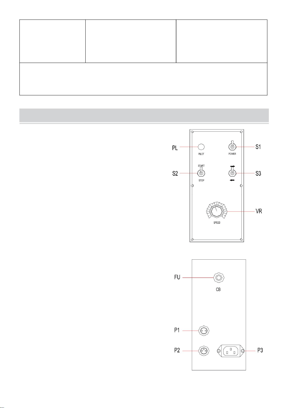
- 6 -
slaglängden är 180 mm
Det vertikala stångslaget på svetsbrännarens fäste är 600 mm, den horisontella staven
set med vapenhållare (med
stång) *1, vapenhållare
*1, manuell *1,
Obs: Diametern på valsens yttre monteringshål är 200-1400 mm;
set med vapenhållare (med
stång) *1, vapenhållare
*1, manuell *1,
1. Frontpanel
omkopplare, S2 ska vara på STOP.)
P1: Motorkontakt (2-stift)
HDTR-1000ÿ
FU: Säkring (CB)
S2: Start/Stopp-brytare (När du använder FOTEN
2. Real Panel
KONTROLLPANEL
S1: Strömbrytare PÅ/AV
P3: Ingångsströmkontakt
VR: Hastighetsjustering
PL: Power Pilot
P2: Fotkontaktkontakt (3-stift)
S3: Omkopplare framåt/bakåt
Machine Translated by Google

FELSÖKNINGSGUIDE
- 7 -
AVHJÄLPA
Fart
4
1. Byt ut en ny motor.
1. Strömsäkringen är bränd.
4. Kontrollera omkopplaren eller
byta ut.
Motor inte
Fram/back-omkopplaren är
byta ut.
potentiometer.
3. Motorstyrning PCB är
2. AC-drivrutinen har ingen ström
lyser inte
Pedal
1. Byt ut en ny säkring.
se nr
Justering
2. Kontrollera transformatorn eller
inmatning
byta ut.
3
rörelse
1. Kontrollera om potentiometer
produktion.
men ingen rörelse.
Motor inte
3. Strömbrytaren är bränd.
Fotkontakten är skadad.
Kontrollera omkopplaren eller
skadad.
3. Byt ut styrkort.
3. AC-drivrutinen är skadad.
4. Ingen strömingång.
ingen rörelse
1. Byt ut en ny motor.
2. Byt ut LED.
2
produktion
byta ut.
ingen rörelse.
2. Motorstyrning PCB har
rörelse
Power pilot
1. Motorn har strömingång
NEJ. SYMPTOM
är 10Kÿ, byt ut annars.
skadad.
1
Kontrollera fotkontakten eller
2. Kontrollera transformatorn eller
men ingen rörelse.
3. Byt omkopplare.
2. Motorstyrning PCB nr
1. Motorn har strömingång
3. Byt ut AC-drivrutinen
2. LED bränd.
1. Skadad
Framåt/Re
styra PCB.
5
MÖJLIG ORSAK
2. Byt ut en ny motor
byta ut.
ingen strömingång
6
Tillverkad i Kina
Machine Translated by Google