21
22
11
45
12
10
42
43
54
(2x)
29
46
51
(7x)
32
(2x)
16
(2x)
31
(2x)
17
(2x)
62
(2x)
34
20
41
51
(2x)
35
70
51
(3x)
23
(2x)
49
15
47
44
38
39
30
51
(12x)
50
40
51
72
54
70
2x
19 50
51 72
73
16 17
31 32
74
20 34 41
46 51 74
75
10 11
12 45
76
42 43
54
77
19
(2x)
54
(4x)
48
51
(6x)
21
22
78
MILWAUKEE TOOL
l
www.milwaukeetool.com
13135 W. LISBON RD., BROOKFIELD, WI 53005
Drwg. 3
BULLETIN NO.
54-49-8411
SERVICE PARTS LIST
CATALOG NO. 0970-20
REVISED BULLETIN
54-49-8410
SPECIFY CATALOG NO. AND SERIAL NO. WHEN ORDERING PARTS
M18 FUEL™ PACKOUT™ 2.5 Gal Wet/Dry Vacuum
DATE
July 2025
WIRING INSTRUCTION
L90B
Pages 2-3
0
00
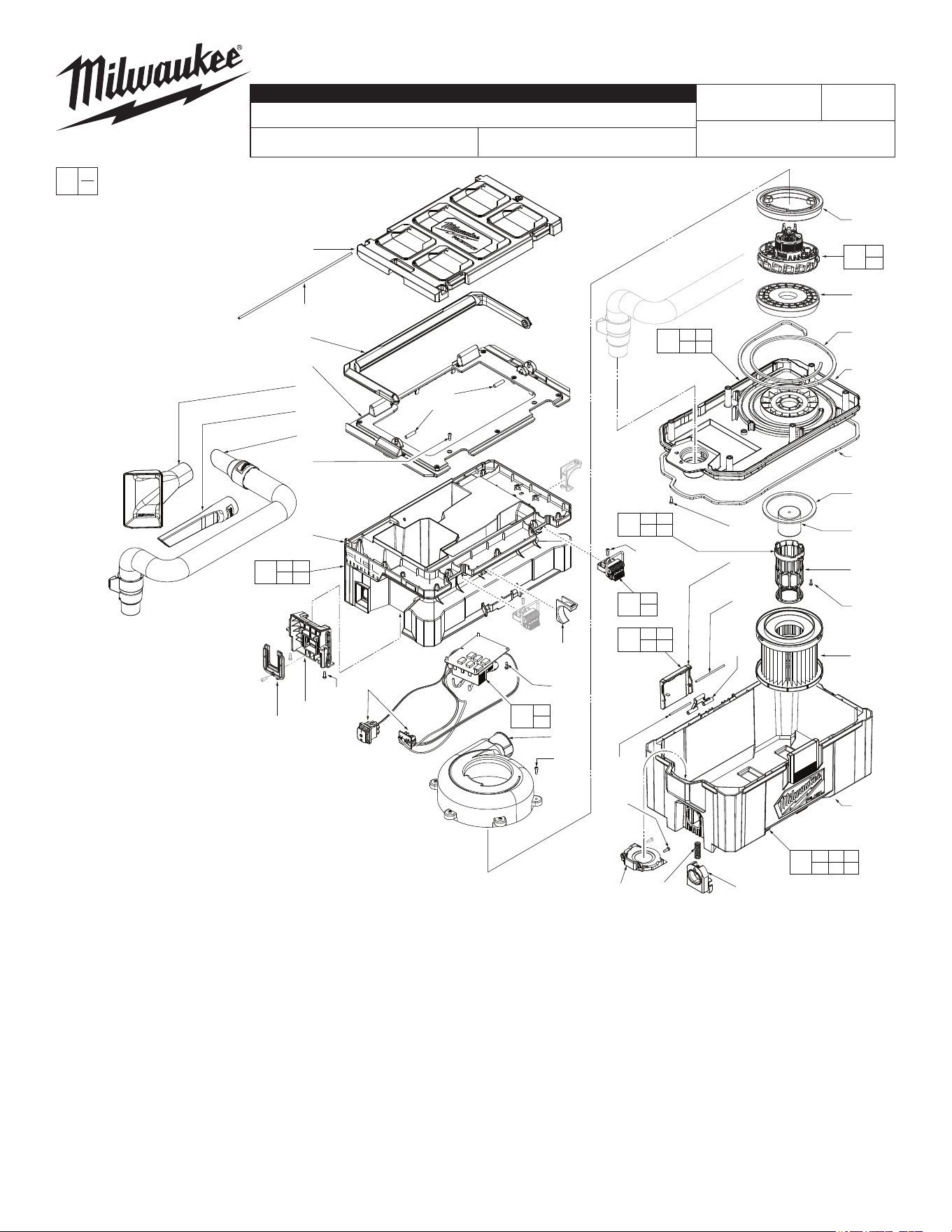
EXAMPLE:
Component Parts (Small #)
Are Included When Ordering
The Assembly (Large #).
FIG. PART NO. DESCRIPTION OF PART NO. REQ.
10 43-44-0036 HEPA Filter Seal (1)
11 43-44-0037 Exhaust Seal (1)
12 43-44-0038 Canister Tank Seal (1)
15 44-60-0123 Top Cover Pin (1)
16 --------------- Tank Latch Pin-Long (2)
17 --------------- Tank Latch Pin-Short (2)
19 43-72-0051 Hose Holder (2)
20 40-50-0213 Latch Spring (1)
21 --------------- Isolator Top (1)
22 --------------- Isolator Bottom (1)
23 44-60-0124 Handle Pin (2)
29 49-90-1900 HEPA Filter (1)
30 49-90-2014 Hose Assembly (1)
31 --------------- Tank Latch Pivot (2)
32 --------------- Tank Latch (2)
34 42-16-0012 Dust Bag Holder (1)
35 44-66-0218 Terminal Block Mounting Plate (1)
38 31-01-0875 Utility Tool (1)
39 31-01-0855 Crevice Tool (1)
40 23-33-0018 Battery Receptacle (1)
41 44-20-0085 PACKOUT™ Latch (1)
42 --------------- Ball Float (1)
43 --------------- Ball Float Cage (1)
44 31-50-0101 Main Body Cover (1)
45 --------------- Connector Plate (1)
46 --------------- Tank (1)
47 31-44-0236 Carrying Handle (1)
48 31-15-0167 Exhaust Chute (1)
49 31-50-0108 Top Cover (1)
50 --------------- Main Body (1)
51 06-82-1081 M4 x 12mm Pan Hd. ST Screw (30)
53 12-20-0267 Service Nameplate (Not Shown) (1)
54 06-82-1083 M3.5 X 10mm Pan Hd. ST Screw (6)
62 05-74-1011 8-18 x 12mm Hi-Lo T15 Screw (2)
70 14-20-0241 Service Electronics Assembly (1)
72 14-46-0316 Service Latch Kit-Main Body (2)
73 14-38-0116 Main Body Service Assembly (1)
74 14-46-0422 Service Latch Assembly-Tank (set of 2) (1)
75 31-01-0173 Tank Service Assembly (1)
76 44-66-0277 Connector Plate Service Kit (1)
77 42-46-0027 Float Ball/Cage Service Kit (1)
78 14-50-0970 Motor/Stator Assembly (1)
SERIAL NO.
FIG. PART NO. DESCRIPTION OF PART NO. REQ.
= Part number change from
previous service parts list.

WIRING INSTRUCTIONS
Going in a Clockwise order, starting at the Yellow Ground wire,
connect the YELLOW PCBA wire to the terminal on the motor's left side.
NOTE - Pull on Motor Wires to ensure they are connected properly.
Connect the RED PCBA wire to the terminal on the motor's top right side.
NOTE - Pull on Motor Wires to ensure they are connected properly.
Connect the BLUE PCBA wire to the terminal on the bottom right of the motor.
NOTE - Pull on Motor Wires to ensure they are connected properly.
Continued next page
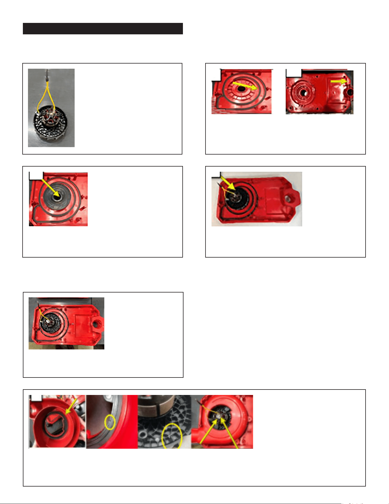
WIRING INSTRUCTIONS - Continued
STEP 1:
Obtain (1) Y-Strap (22-56-0061)
and secure the wire's longest leg
to the motor clip.
Pull on the Yellow Ground Wire to
ensure it is connected properly.
STEP 2: Obtain (1) Plate Connector.
Ensure the tank seal and exhaust seals are present
and complete with no gaps.
STEP 3: Obtain (1) Bottom Isolator (31-55-0017)
and secure it onto the connector plate.
STEP 4: Place (1) Motor and secure it into the
Connector Plate and pass to the next station.
PART 1) Motor and Connector Plate Assembly
PART 2) Connector Plate and Volute Assembly
STEP 1: Obtain the previously assembled
Connector Plate and Motor Assembly
STEP 2: Obtain (1) Volute, Exhaust and ensure (1) Top, Isolator (31-55-0019) is installed. Set the volute
assembly into place over the motor as shown. Make sure the notch in the isolator matches up correctly with the
notch on the motor. The terminal ground wire should be in the 1 o'clock position as shown.