
7
6
(4x)
8
52
(4x)
10
52
(2x)
13
11
14
15
(2x)
16
(4x)
26
(2x)
1
(4x)
52
(2x)
21
24
19
20
(2x)
22
25
(4x)
1
(8x)
30
31
32
33
36
(2x)
37
(2x)
38
35
(2x)
40
41
52
(3x)
42
52
(5x)
39
34
1
(5x)
28
9
18
20
74
19
20
75
21 22 23
24 25 52
70
1 11 12 13 14
15 16 26 27 52
71
2
3
52
(12x)
4
(4x)
2 3
4
72
46
45
48
47
(4x)
6
(2x)
27
(2x)
18 17
(2x)
12
1
(12x)
5
61
90
91
45 46
47 48
83
55
62
1
(2x)
23
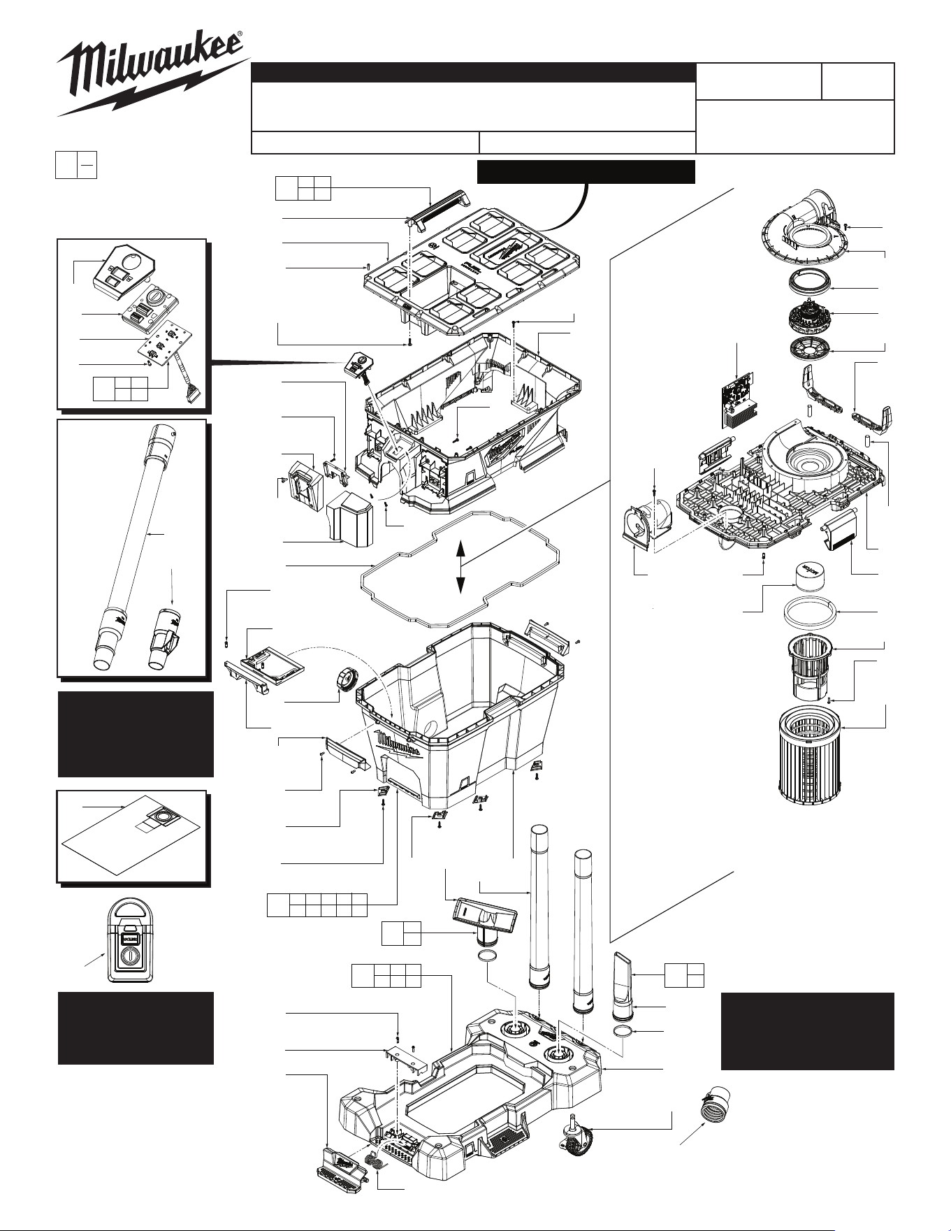
#90: For VACLINK™
Wireless Remote
Service Parts refer to
the 0952-20 SPL.
Refer to the next page for:
The corresponding Parts
List, Torque Specications
Chart, and Wire Routing.
#55: You must order
the VACLINK™ nozzle
(62) when replacing the
hose assembly (55).
0
00
EXAMPLE:
Component Parts (Small #)
Are Included When Ordering
The Assembly (Large #).
MILWAUKEE TOOL
l
www.milwaukeetool.com
13135 W. LISBON RD., BROOKFIELD, WI 53005
Drwg. 1
PACKOUT™ Compatibility
SERVICE PARTS LIST
BULLETIN NO.
PN0005064
SPECIFY CATALOG NO. AND SERIAL NO. WHEN ORDERING PARTS
REVISED BULLETIN
DATE
Aug. 2025
M18 FUEL™ NEXUS™ 6 Gallon Wet/Dry Vacuum
w/ VACLINK™ (18V)
WIRING INSTRUCTION
See Page 2
CATALOG NO. 0914-20 SERIAL NO. R11A
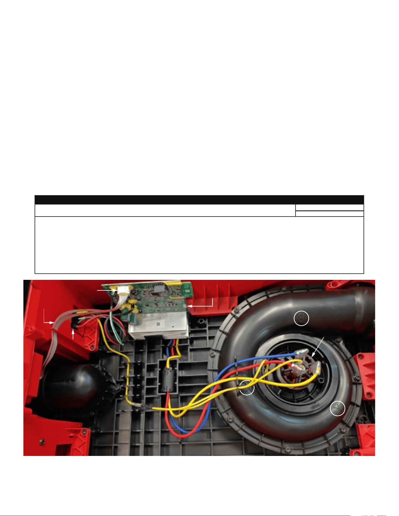
Before you disassemble the tool, record the wire routings and their
positions in the wire guides and traps.
Make sure that all components of the electronics kit are aligned and
installed correctly in the housing recesses.
Do not strain or stretch wires. Make sure that all wires and sleeves are
pushed fully down into wire guides and traps.
Before you install the mid-frame onto the head, make sure they align
correctly with no interferences.
Before you install the battery, check that the switch operates correctly.
After you install the battery, make sure the switch triggers move freely and
function correctly before you operate the tool.
FIG. PART NO. DESCRIPTION OF PART NO. REQ.
1 06-82-9220 M4 x 16mm Pan Hd. PT T-20 Screw (31)
2 --------------- Top Handle (1)
3 --------------- Packout Top (1)
4 05-78-0003 M5 x 17mm Pan Hd. Tapt. T-25 Screw (4)
5 --------------- Head Shell (1)
6 05-78-0044 M3 x 12mm Pan Hd. Tapt. T-10 Screw (6)
7 22-56-0002 Terminal Block Cover (1)
8 31-01-0118 Battery Rail (1)
9 31-15-1101 Battery Cover (1)
10 45-06-0002 Rubber Tank Gasket (1)
11 42-52-1002 Drain Cap (1)
12 --------------- 6 Gallon Tank (1)
13 42-16-0001 Bag Holder Attachment (1)
14 42-16-0002 Bag Holder Screw-In Attachment (1)
15 14-34-1001 Tank Handle (2)
16 05-81-0013 M4 x 10mm Pan Hd. ST Phillips Screw (4)
17 49-90-0001 Extension Wand Assembly (1)
18 --------------- Utility Tool (1)
19 --------------- Crevice Tool (1)
20 --------------- Color Ring (2)
21 --------------- Pedal Cover (1)
22 --------------- Cart Base (1)
23 40-50-0004 Torsion Spring (1)
24 31-01-0119 Tank Release Pedal (1)
25 45-94-0001 Caster Assembly (4)
26 44-34-0003 Rubber Tank Foot (2)
27 44-34-0004 Rubber Tank Foot (2)
28 43-33-0001 Inlet Elbow (1)
30 31-01-0121 CD Volute Top (1)
FIG. PART NO. DESCRIPTION OF PART NO. REQ.
31 31-50-0109 Upper Motor Isolator (1)
32 31-50-9000 Motor (1)
33 31-50-0116 Lower Motor Isolator (1)
34 14-20-1104 Main PCBA (1)
35 31-01-0122 Tank Buckle (2)
36 31-01-0123 Hose Reset (2)
37 31-01-0109 Pin (2)
38 31-01-0126 Mid Frame (1)
39 42-46-0001 Ball Float (1)
40 45-06-0004 Filter Seal (1)
41 42-46-0002 Float Ball Cage (1)
42 49-90-1978 Filter Assembly (Available in Stores) (1)
44 23-94-0104 Wire Assembly (Not Shown) (1)
45 --------------- Rubber Button Pad (1)
46 --------------- UI Cover (1)
47 05-78-0004 M2 x 7mm Pan Hd. ST Phillips Screw (4)
48 --------------- UI PCBA (1)
52 05-78-0005 M4 x 14mm Pan Hd. ST T-20 Screw (28)
55 49-90-1996 9' Hose Assembly (Available in Stores) (1)
62 14-37-0001 Nozzle (1)
70 0943-20 Cart Assembly (1)
71 0922-20 Tank Assembly (Available in Stores) (1)
72 14-46-1108 Packout Top Service Kit (1)
74 49-90-2011 Utility Tool Service Assembly (1)
75 49-90-1988 Crevice Tool Service Assembly (1)
83 14-46-1107 UI Service Assembly (1)
12-20-1104 Service Nameplate (Not Shown) (1)
90 0952-20 VACLINK™ Wireless Remote (1)
91 31-01-0127 Dust Extraction Tool (1)
CD Volute Top has letter designations
that correspond to motor terminal
wire connections from Main PCBA
and Battery Terminal Block:
B = Blue
Y = Yellow
R = Red
UI connector to MainPCBA
UI PCBA wires
Main
PCBA
Ferrite
Bead
Battery
Terminal
Block
Motor
SCREW TORQUE SPECIFICATIONS
SEAT TORQUE
FIG. PART NO. DESCRIPTION OF FASTENER WHERE USED (lb-in) (kgf-cm)
1 06-82-9220 M4 x 16mm Pan Hd. PT T-20 Screw Volute, Elbow, Battery Cover, Head Shell 5.2-6.9 6-8
1 06-82-9220 M4 x 16mm Pan Hd. PT T-20 Screw Feet 4.7-5.6 5.5-6.5
4 05-78-0003 M5 x 17mm Pan Hd. Tapt. T-25 Screw Top Handle, Packout Top 9.5-11.2 11-13
6 05-78-0044 M3 x 12mm Pan Hd. Tapt. T-10 Screw Terminal Block Cover, Battery Cover 4.7-5.6 5.5-6.5
16 05-81-0013 M4 x 10mm Pan Hd. ST Phillips Screw Tank Handles 4.7-5.6 5.5-6.5
47 05-78-0004 M2 x 7mm Pan Hd. ST Phillips Screw UI PCBA 1.3-2.1 1.5-2.5
52 05-78-0005 M4 x 14mm Pan Hd. ST T-20 Screw Packout Top, Batt. Rail, Bag Holder, Cage 5.2-6.9 6-8