
User Manual
VT07-B21A/ VT07-B22A/ VT07-B23A/ VT10-B21A
Version: 1.0
Due to the regular upgrades of systems and products, ZKTeco could not guarantee exact
consistency between the actual product and the written information in this manual.
Remark
Please follow the user manual for correct installation and testing. If there is
any doubt please call our tech-supporting and customer center.
Our company applies ourselves to reformation and innovation of our
products. No extra notice for any change. The illustration shown here is
only for reference. If there is any difference, please take the actual product
as the standard.
The product and batteries must be handled separately from household
waste. When the product reaches the end of service life and needs to be
discarded, please contact the local administrative department and put it in
the designated collection points in order to avoid the damage to the
environment and human health caused by any disposal. We encourage
recycling and reusing the material resources.

CATALOG
Product Features ............................................................ 1
Technical Parameters ..................................................... 1
Product Executive Standard .......................................... 2
Pictures ........................................................................... 3
Operations ...................................................................... 5
1.
VOIP ............................................................................ 6
2.
Security ..................................................................... 12
3.
Elevator .................................................................... 20
4.
Service ................................................................................................ 20
Web Settings ................................................................ 23
System Configuration .................................................. 27
System Diagram ........................................................... 28
Installation .................................................................... 30
Troubleshooting ........................................................... 33
Safety Precaution ......................................................... 34

-1-
Product Features
1. Building intercom application:
VOIP: Support video call, monitoring, unlocking, VOIP communication
and call record checking.
Security: Support 8 alarm zones with 3 states, alarm zone and scene
setup.
Others: Support Android systems applications.
Support connection to audio extension (VT07-B21A/VT07-B22A/VT07-
B23A/VT10-B21A optional).
Support Wi-Fi network communication and Bluetooth transmission (Optional).
2. Operating system: VT07-B21A system: Android 4.4.2
VT07-B22A/VT07-B23A/VT10-B21A: Android 6.0.1
Technical Parameters
Voltage: DC 12V
POE (VT07-B21A/VT07-B22A/VT07-B23A/VT10-B21A optional)
Rated power: 10W
Standby power consumption: 3W
Display screen: 7'' / 10.1''
Touch screen: capacitive touch screen
Resolution: 10.1'': 1024X600(VT10-B21A)
7'': 1024X600(VT07-B21A/VT07-B22A/ VT07-B23A)
Camera: 640x480CMOS (Optional)
Operating temperature: -10℃~+55℃
Storage temperature: -10℃~+60℃
Storage Relative humidity: 20%~85%
Memory: 512MB
1GB (optional)
CPU: Quad core 1.3GHz
Flash: 4GB

-2-
Product Executive Standard
◇
GB/T 31070.1-2014 "Building Intercom Systems—Part 1: General Technical Requirements”.
◇
GA 1210-2014 "Security Technical Requirements for Building Intercom Systems”.
◇
GB /T12663-2019 "General Specifications for Burglar-alarm Control Units”.
◇
GB /T 32581-2016 "Specifications for Intrusion and Hold-up Alarm System”.
◇
GBT / 31070.2-2018 "Building Intercom System Part 2: Technical Requirements for
Digital Building Intercom Systems”.
◇
GBT / 31070.4-2018 "Building Intercom System Part 4: Application Guidelines”.
◇
GB / T 37845-2019 "Technical Requirements for Home Security Intelligent Management
Systems”.
◇
DB31 / T294-2018 "Requirements of Intelligent Security Technology in Residential District”.
◇
DB31T 1086-2018 "Requirements of Applications for Intrusion Alarm System”.
-3-
Pictures
Model: VT10-B21A
Power
Return
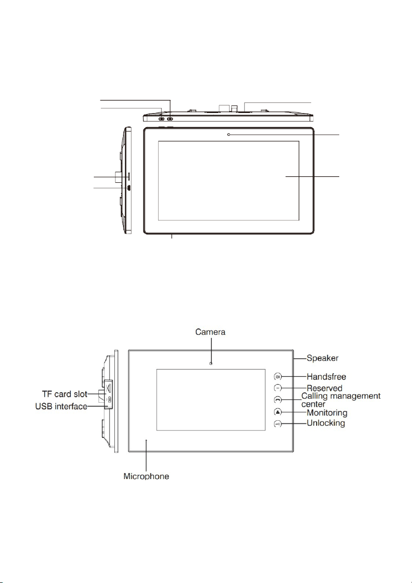
TF card slot
USB interface
Speaker
Camera
Display
screen
Microphone
Model: VT07-B23A
-4-
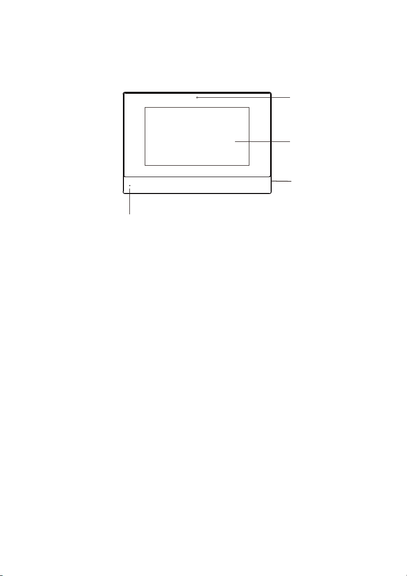
Model: VT07-B21A/VT07-B22A
Camera
Display
screen
Speaker
Microphone
-5-
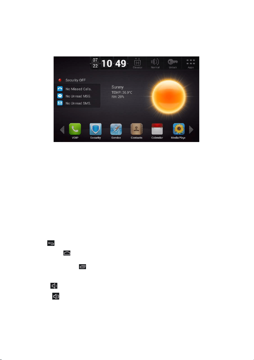
Operations
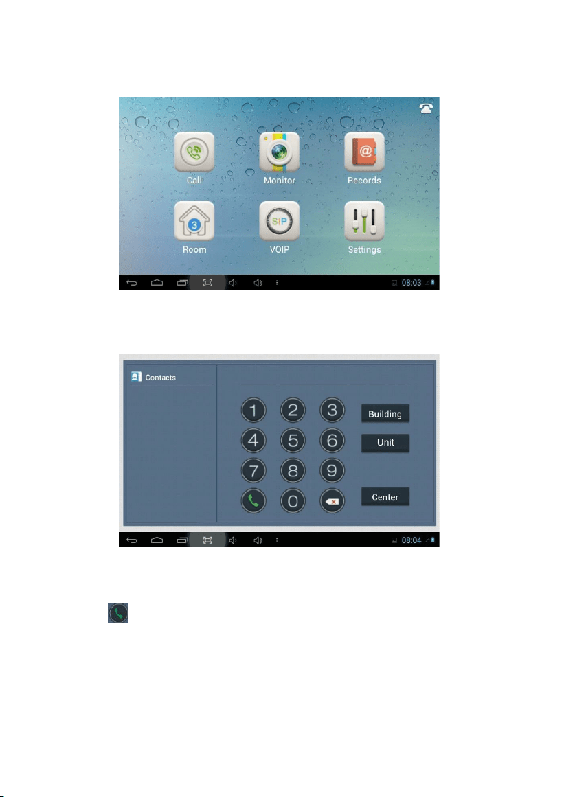
Main interface: VOIP, Security, Service, Contacts, Calendar, Media player.
Shortcut key: Elevator, Out, Unlock and Apps.
1.
The main interface will remind user when there are missed calls, unread MSG and
SMS.
2.
The state of weather is synchronously updated by NTP.
Status bar: Return, Main interface, Background program, Volume-,Volume+.
When the user enters into secondary menu, the interface displays the following icons at
the bottom of the screen.
Status bar instruction:
1.
Return : Click it to return to previous menu.
2.
Main interface : Click it to return to main interface.
3.
Background program : Click it to display the operating program running in the
background.
4.
Volume- : Click it to reduce the volume.
5.
Volume+ : Click it to increase the volume.
-6-
1.
VOIP
Clicking “VOIP” icon on the main interface, the system will enter the following interface:
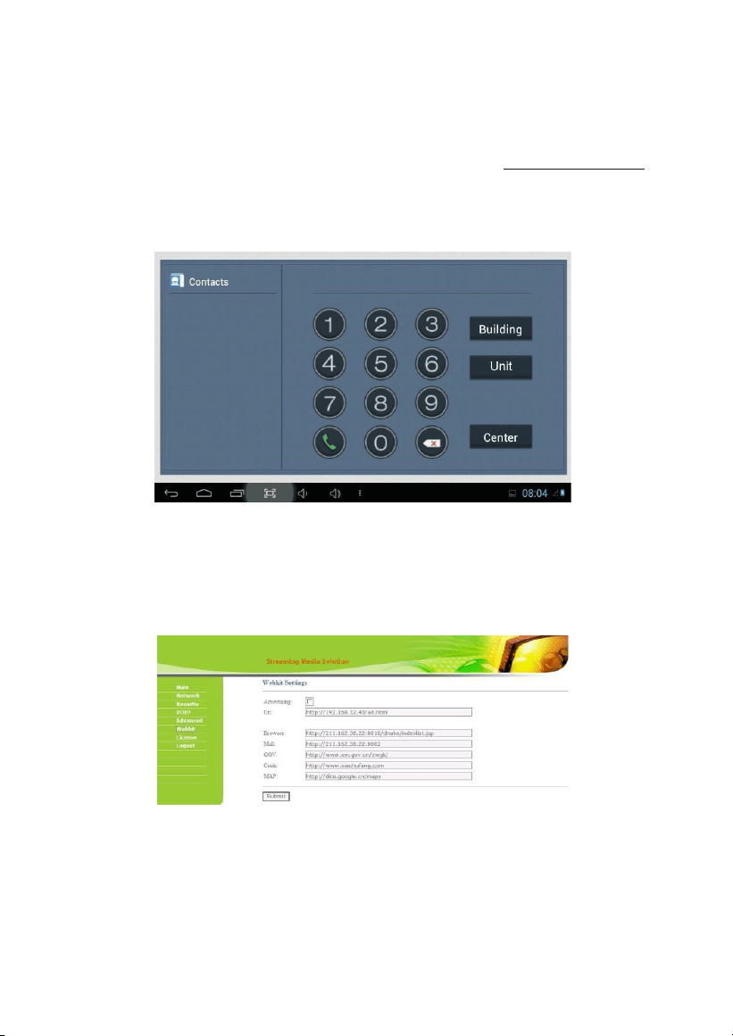
1.1 Call
Clicking “Call” icon, the system will enter the following interface:
1.1.1
Call unit resident
Input 1-3 digits building No.+ “Building” + 2-digit Unit No. + “Unit” +4-digit room No.,
then click icon to call.
The system will enter into the following interface:
-7-
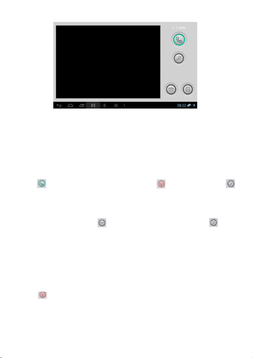
When the call is answered, the system will enter into call state:
①If there is a camera, the caller’s image will be displayed on the screen;
②When the call is answered, the video will be uploaded into the indoor monitor.
When the outdoor panel, wall panel or flat camera calls, the indoor monitor will ring;
when outdoor panel calls indoor monitor, the image from outdoor panel will be
displayed on the indoor monitor; if there is no answer within 25 seconds, the call will
be ended.
Click icon to communicate with outdoor panel; click icon to end the call; click
icon to unlock the door.
Remark: visual intercom function between households is optional.
You can make audio and video recording during communication (TF card should be
inserted into indoor monitor). icon to take a snapshot of the visitor; click icon
to save the video and image for current communication.
The system’s default call duration is 120s.
1.1.2
Call management center
Clicking “Center” icon to call management center, the system will call management
center No.1-No.5 successively. If the management center cannot be searched or call failed,
the system will automatically call next management center. When the management
center answers, it will ring and stop calling next one.
Click icon to end the communication.
1.2 Monitor
Clicking “Monitor” icon, the system will enter the following interface:
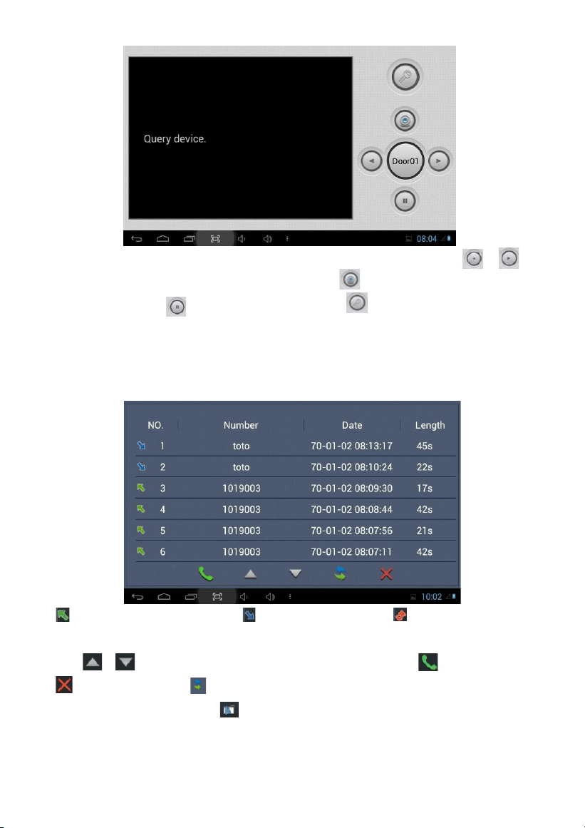
-8-
Click “Door01” icon to switch outdoor panel and flat camera mode, then click or
icon to select the area you want to monitor, and click icon to monitor the outdoor
panel or flat camera. icon to end monitoring. Click icon to unlock the door.
Remark: The system’s default monitoring time is 25s.
1.3 Records
Clicking “Records” icon, the system will enter the following interface:
refers to call-out record; refers to call-in record; refers to missed call
record. It can save up to 64 records.
Click or icon to search for records. Select one record and click icon to call; click
icon to delete it. Click icon to back-up.
If there is snapshot image, click icon to view it.
-9-
1.4 Room
Click “Room” icon, then input 1-16 digits password (the default password is 123456) to enter
into the following interface:
Warning: Please revise synchronous No.(6 digits) as soon as possible after you read
the user’s manual. The synchronous No. of all indoor monitors in one household
must be the same.
Input the 3-digit Building No. such as 001, and then click “OK” to finish the building No.
setting.
The setting method of Unit No., Floor No., Room No., Device No. and Synchronous No. is
the same as the one of Building No.. The Unit No., Floor No. and Room No. are limited to 2
digits respectively. When Device No. is set to be 0, the indoor monitor is regarded as the
main; when Device No. is set from 1 to 5, as the sub1 to sub5.
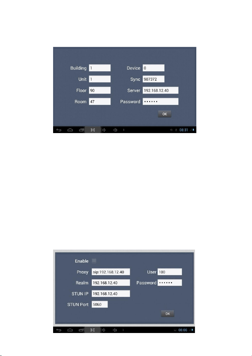
1.5 VOIP
Clicking “VOIP” icon, the system will enter the following interface:
-10-
Proxy: sip proxy server URL, the form is sip:ip or sip: realm name.
Realm: the scope for the device, is the same with IP or realm name.
Password: the password to access proxy server, offered by the administrator of sip proxy server.
Stun IP and port: the public network server IP and port crossed by audio/video NAT.
To connect with SIP phone, check “Enable” and input the registered SIP account.
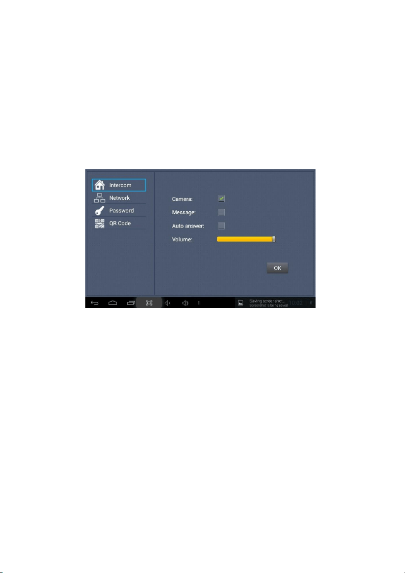
1.6 Settings
Clicking “Settings” icon, the system will enter the following interface:
1.6.1
Intercom
Check “Camera” , “Message” or “Auto answer” to enable corresponding function, then
click “OK” icon.
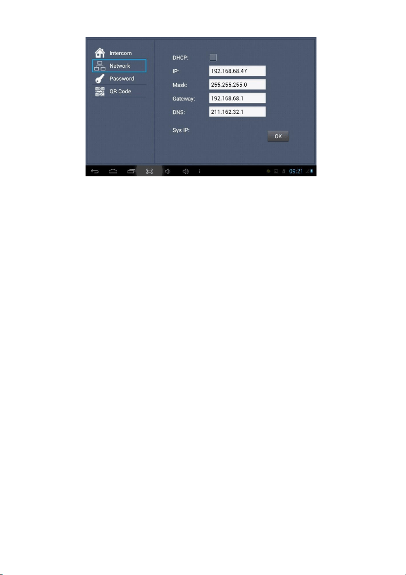
1.6.2
Network
Click “Network” icon to enter into the following interface:
-11-
After using the DHCP, the router will automatically distribute IP address.
Other settings are the same as the ones of Apps.
Sys IP: the system will automatically display IP address of the indoor monitor. IP address is
unique.
The default Mask address is 255.255.255.0. Normally, it is unnecessary to modify. If you would
like to modify it, clicking the setting box twice, a keypad will pop up. Enter your new Mask
address.
The Gateway in one system must be in the same segment.
DNS: domain name resolution address (DNS of local operator). If the indoor monitor is
used in external network, the address must be completed correctly; if it is used in
internal network, the address can be ignored.)
Click “OK” to save the settings.
Remark: the settings should be made after inputting password to enter into room No.
settings.
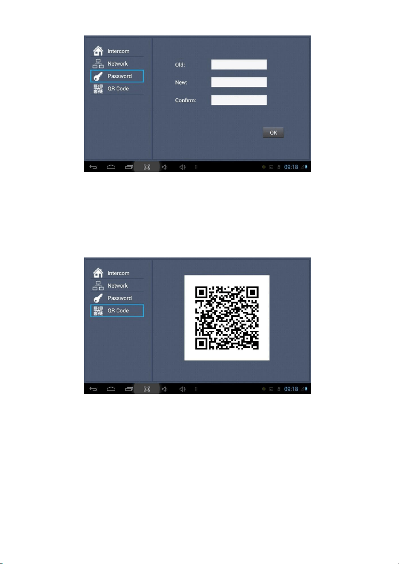
1.6.3
Password
Clicking “Password” icon to enter into the following interface:
-12-
You can set the new system password with 1-16 digits (the default password is 123456).
System password is used for system settings.
1.6.4
QR Code
Click “QR Code” icon to enter into the following interface:
Scanning the QR code with mobile APP, it will be synchronized with the indoor monitor.
2.
Security
Clicking “Security” icon on the main interface, the system will enter into the following
interface:
-13-
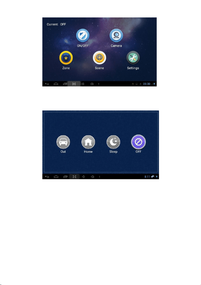
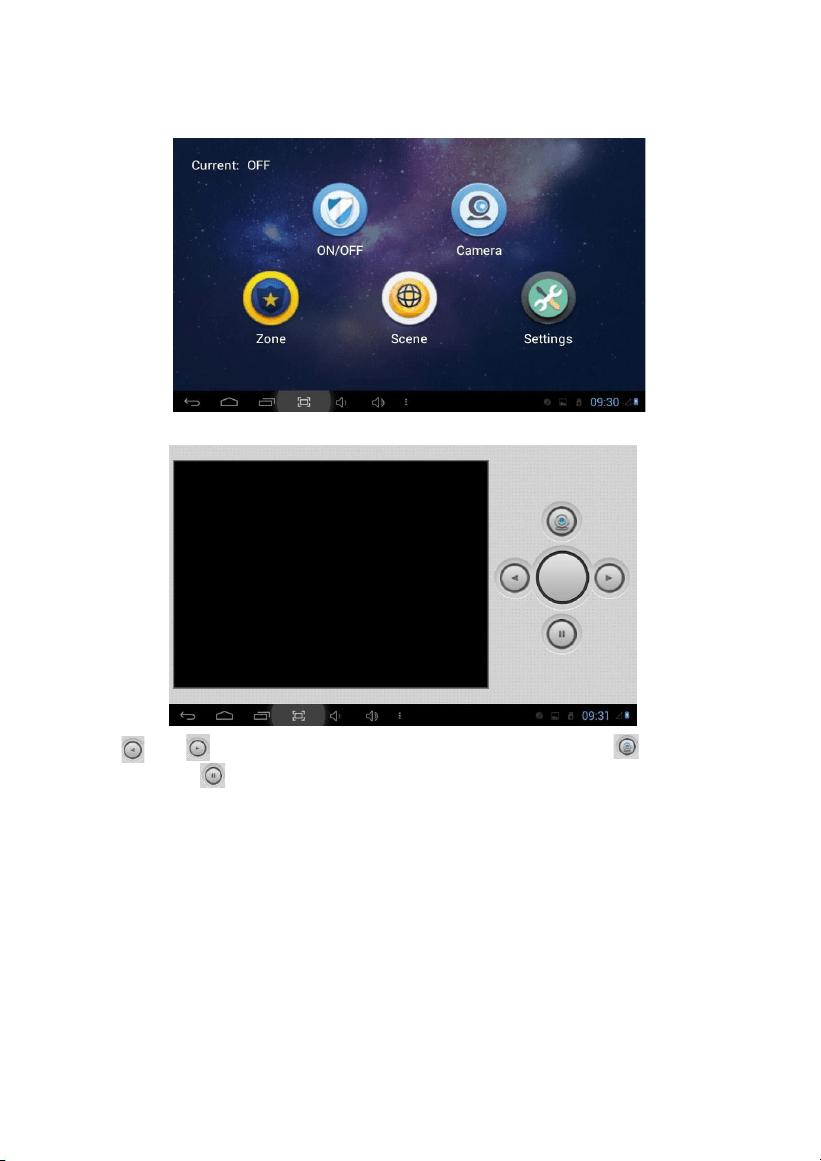
2.1 ON/OFF
Clicking “ON/OFF” icon, the system will enter the following interface:
2.1.1
ON
Clicking “Out”, “Home”, or “Sleep” icon to activate the alarm sensors, the icon on the main
interface will light with a “Di-Di” tone and this icon will always light up.
2.1.2
OFF
(1)
During the alarm delay time, clicking “OFF” icon, the system will give a tone, then the
alarm is disabled.
(2)
Input user password (the default password is 1234) to disable the alarm under alarm
ON status.
-14-
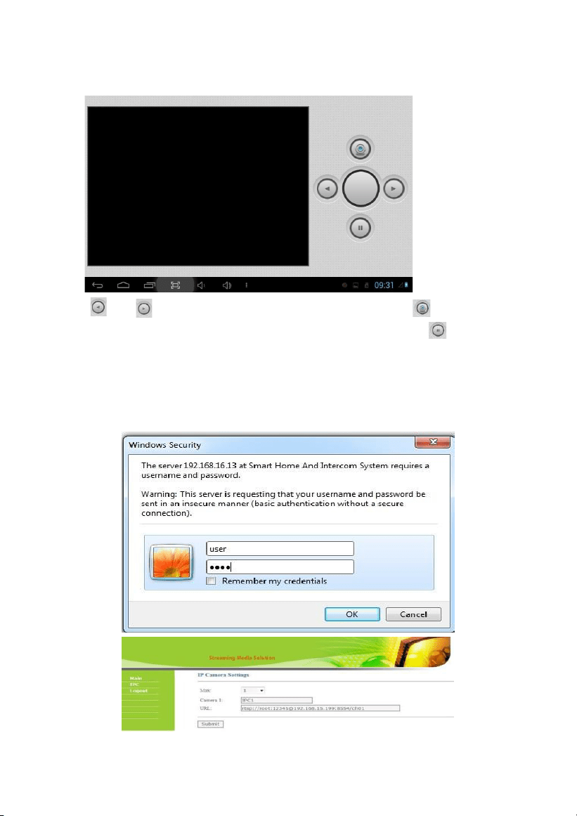
2.2 Camera
Clicking “Camera” icon, the system will enter into the following interface:
Click “ ” or ” button to select camera you want, and then click to monitor the IP
camera. During the monitoring, if you want to cancel monitoring, click to stop it.
2.2.1
IP Camera Setting
Login the webpage of indoor monitor by username: user, password:1234, then you can
access the following webpage:
-15-
Fill the RTSP format: rtsp:// user: password@ Camera IP. IP is the IP address of your IP
Camera. Then you can monitor IP Camera in Security menu on your indoor monitor:
Clicking “Camera” icon, the system will enter into the following interface:
Click ” or “ ” button to select IP Camera to monitor, and then click
icon to
monitor. Click to stop monitoring.
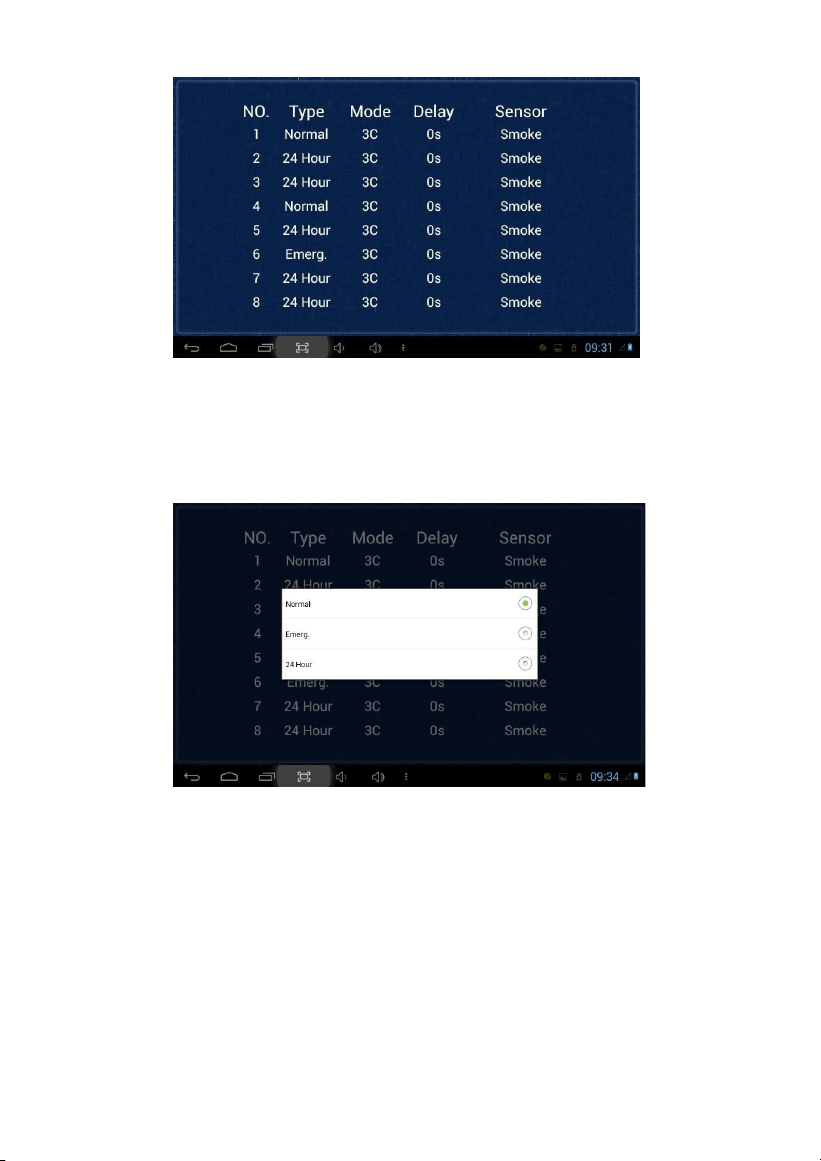
2.3 Zone
Remark: the settings should be made when alarm is OFF.
Clicking “Zone” icon and inputting 1-16 digits password (the default password is 1234),
the system will enter into the following interface:
-16-
2.3.1
Alarm Type
Clicking type input box, it will pop up a dialog box as the following. In this interface, you
can set alarm Type as: Normal, Emergency and 24H. 24H and Emergency type are always
active.
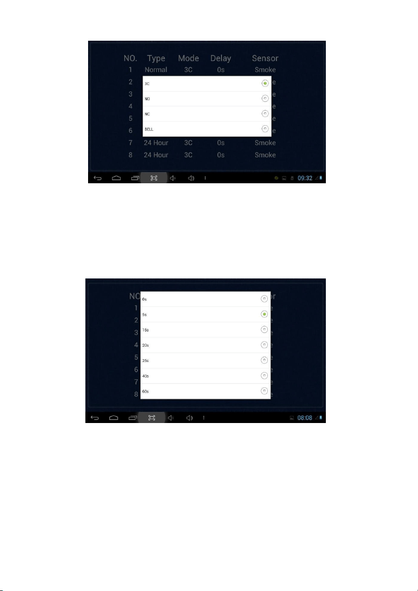
2.3.2
Mode
Clicking mode setting box, it will pop up a dialog box as the following interface.
In this interface, you can set mode as: 3C, NO, NC and BELL.
-17-
2.3.3
Delay Time
It refers to the delay time of giving an alarm. Clicking Delay setting box, it will pop up a
dialog box as the following interface with selections: 0s, 5s, 15s, 20s, 25s, 40s or 60s as the
desired delay time. For example, you select the delay time: 5s. Once the alarm sensor is
triggered, 5 seconds later, the indoor monitor will sound sirens.
2.3.4
Sensor Type
Clicking sensor type input box, it will pop up a dialog box as the following interface. Each
sensor type can be set up as: Smoke, Gas, PIR, Door, Window, Panic, Flood, Pull Cord or
Bed Mat.
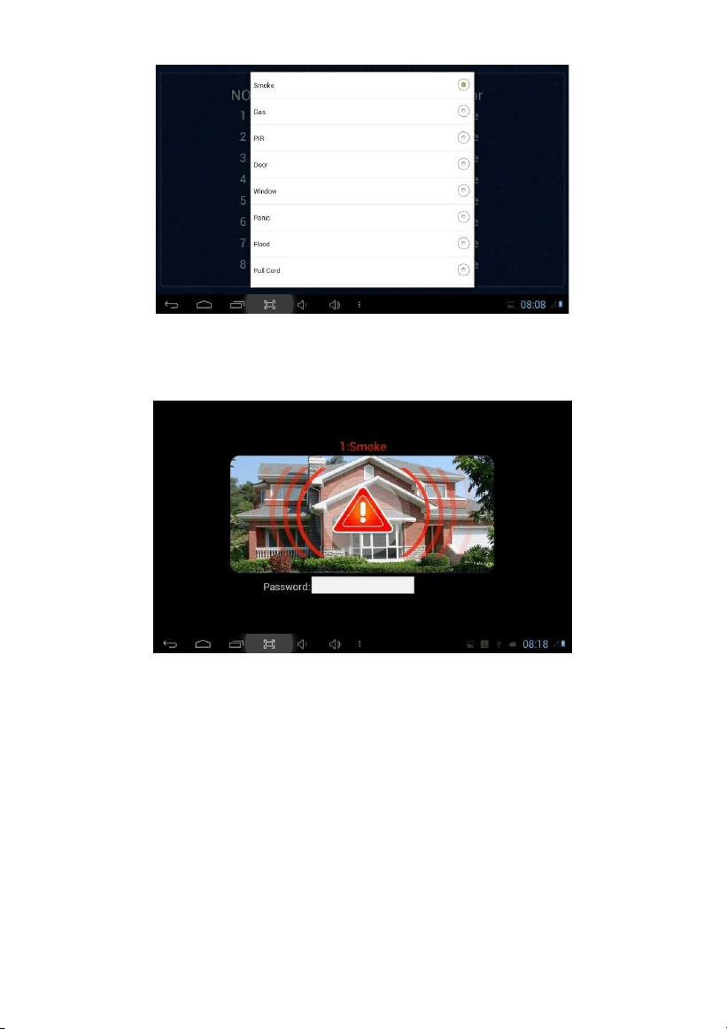
-18-
When alarm sensor is triggered, the indoor monitor will make a loud alarm sound. The
system will enter into the following interface and send alarm message to management
center (if your system is installed with management center):
You can see the No. and sensor type in red showed at the top of interface. For example:
“2:Smoke” indicates that in Zone 2 Smoke sensor is triggered.
To stop the alarm sound, input the password (the default password is 1234).
-19-
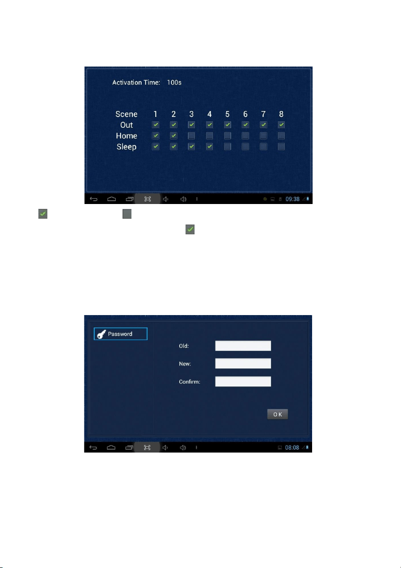
2.4 Scene
Clicking “Scene” icon, the system will enter into the following interface:
refers to Alarm ON, refers to Alarm OFF. To set the sensor of alarm
stations, you can
click the corresponding station with icon. Click activation time to choose the
corresponding time. The options of activation time include NONE, 30s, 40s, 60s, 100s and
300s.
2.5 Settings
Clicking “Settings” icon, the system will enter into the following interface:
You can set the new user password with 1-16 digits (the default password is 1234). User
password is used for security.
-20-
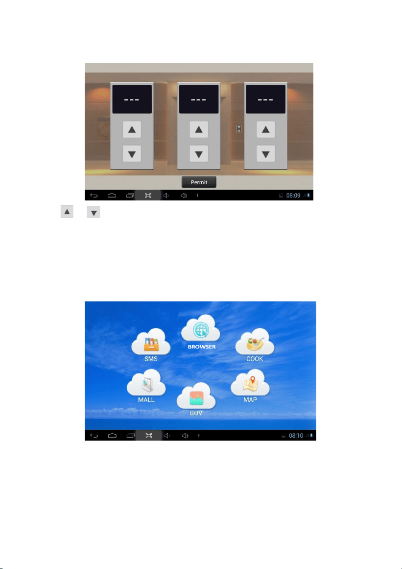
3.
Elevator
Clicking “Elevator” icon, the system will enter into the following interface:
Click or icon to control the elevator to go up and down. Click “Permit” icon to allow
access to the floor where the indoor monitor is located.
Remark: To support this interface, your system must connect with “Elevator Control” module.
Kindly check with your system provider.
4.
Service
Clicking “Service” icon on the main interface, the system will enter into the following interface:
-21-
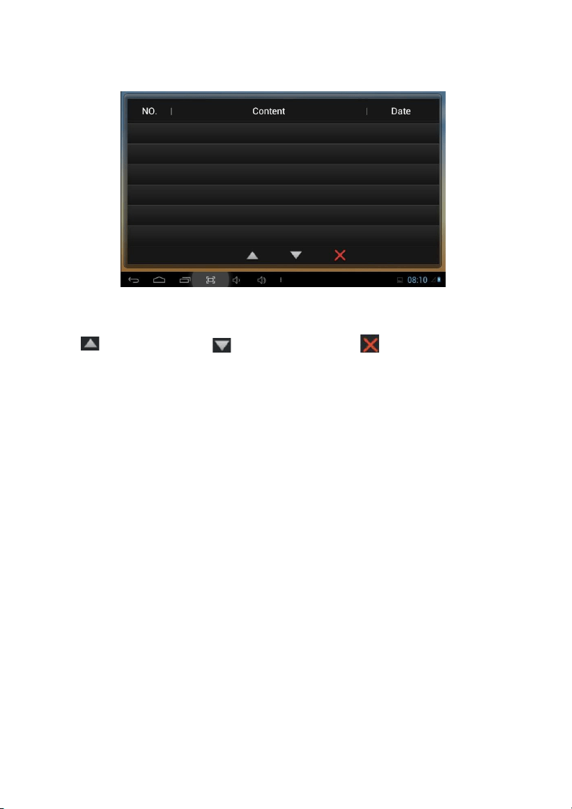
4.1 SMS
Clicking “SMS” icon, the system will enter into the following interface:
Note: only clicking the management software on PC which is usually located at guard
center, so can indoor monitor receive the message sent by PC.
Click icon to page up; click icon to page down; click icon to delete
the record.
64 records can be received in SMS at most.

-22-
4.2 BROWSER
Clicking “BROWSER” icon, the system will enter into the web page linked with the
indoor monitor (the function should be supported by external network).
You can also set the default link for “COOK”, “MAP”, “GOV” and “MALL” in the webpage
on indoor monitor.
-23-
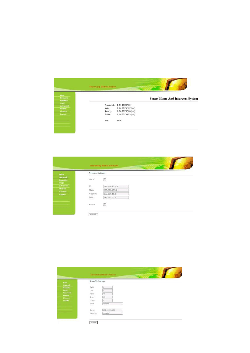
Web Settings
Please refer to 1.6.2 to view IP address.
Connect the indoor monitor and computer by network switch. Input the indoor monitor’s
IP address in the browser, then input user name and password (the default user name is
“admin”, the password is “123456") to enter into the web setting interface.
1.
Network
Click “Network” icon to enter into the following interface:
The user can change the IP address of indoor monitor here. Checking the box of the
ethwifi, wifi and wired network will work synchronously, but this is only valid for those
indoor monitors with wifi function.
2.
RoomNo
Click “RoomNo” icon to enter into the following interface:
The settings are the same as the ones of indoor monitor.
-24-
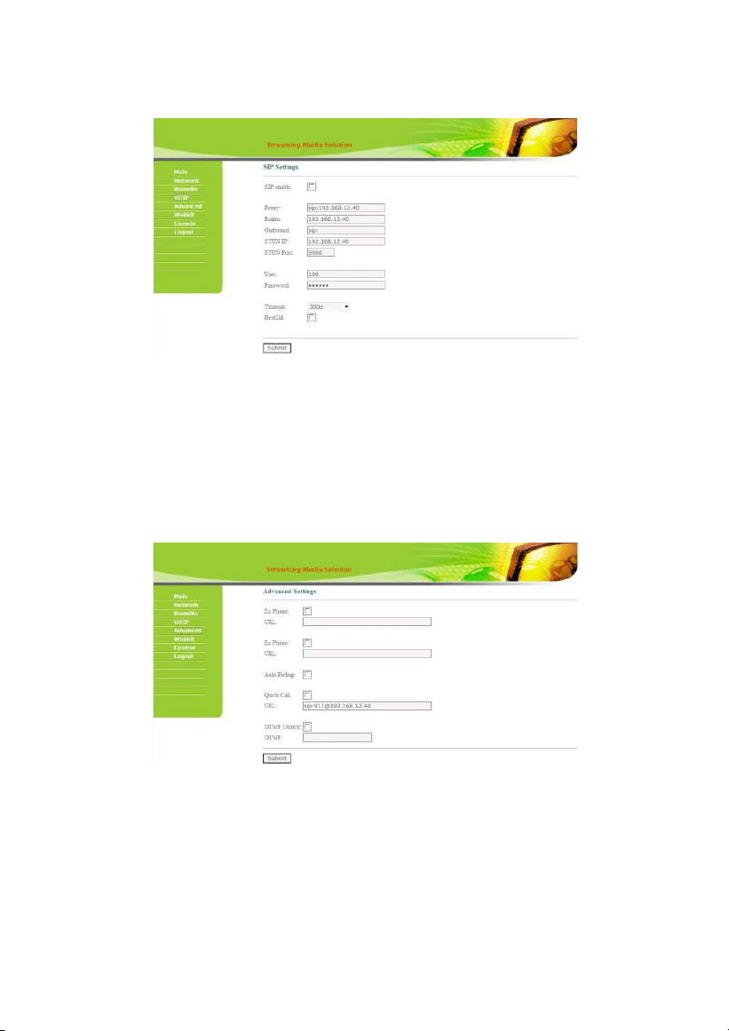
3.
VOIP
Click “VOIP” icon to enter into the following interface:
The settings are the same as the ones of indoor monitor.
To connect with SIP phone, check “SIP Enable”, and input the number registered in SIP server.
Timeout: Talking time settings.
Click “Submit” icon to save the settings.
4.
Advanced
Click “Advanced” icon to enter into the following interface:
Ex Phone: input IP address of other manufacturer’s SIP device. It refers to other factory’s
VOIP device which is used as sub indoor monitor. When outdoor panel calls indoor
monitor, SIP device will ring at the same time. Other terminals will stop ringing when one
of the indoor monitor or SIP device answeres the call.
-25-
Auto Pickup: checking the box, the indoor monitor will automatically answer the call,
when outdoor panel calls but there is no answer within 10s.
Quick Call: If you want to click Center icon to call other SIP device (for example IP address
is 192.168.15.100), you can check this option, input for example sip:[email protected]
(1
can be any number ), and then save the settings.
When you click the icon, it will call this SIP device.
Remark: the address can be the SIP address of indoor monitor or other factory’s VOIP device.
Click“Submit” icon to save the settings.
5.
Webkit
Click “Webkit” icon to enter into the following interface:
Advertising: use web page as the image. Checking the box, when there’s advertisement
pushed from management software, it will display when the indoor monitor is in standby
state.
-26-
Browser: input the linking address in the box. As there is a “BROWSER” icon on the indoor
monitor, when the user clicks the icon, it will switch into the linked web page.
Click “Submit” icon to save the settings.
6.
License
It is reserved.
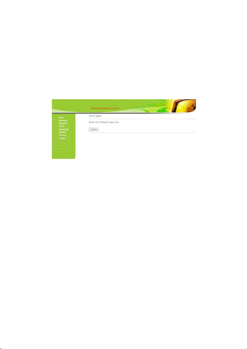
7.
Logout
Click “Logout” icon to enter into the following interface:
Clicking “Submit” icon, the user will log out of the system.
-27-
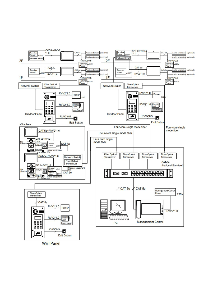
System Configuration
-28-
CAT-5e
System Diagram
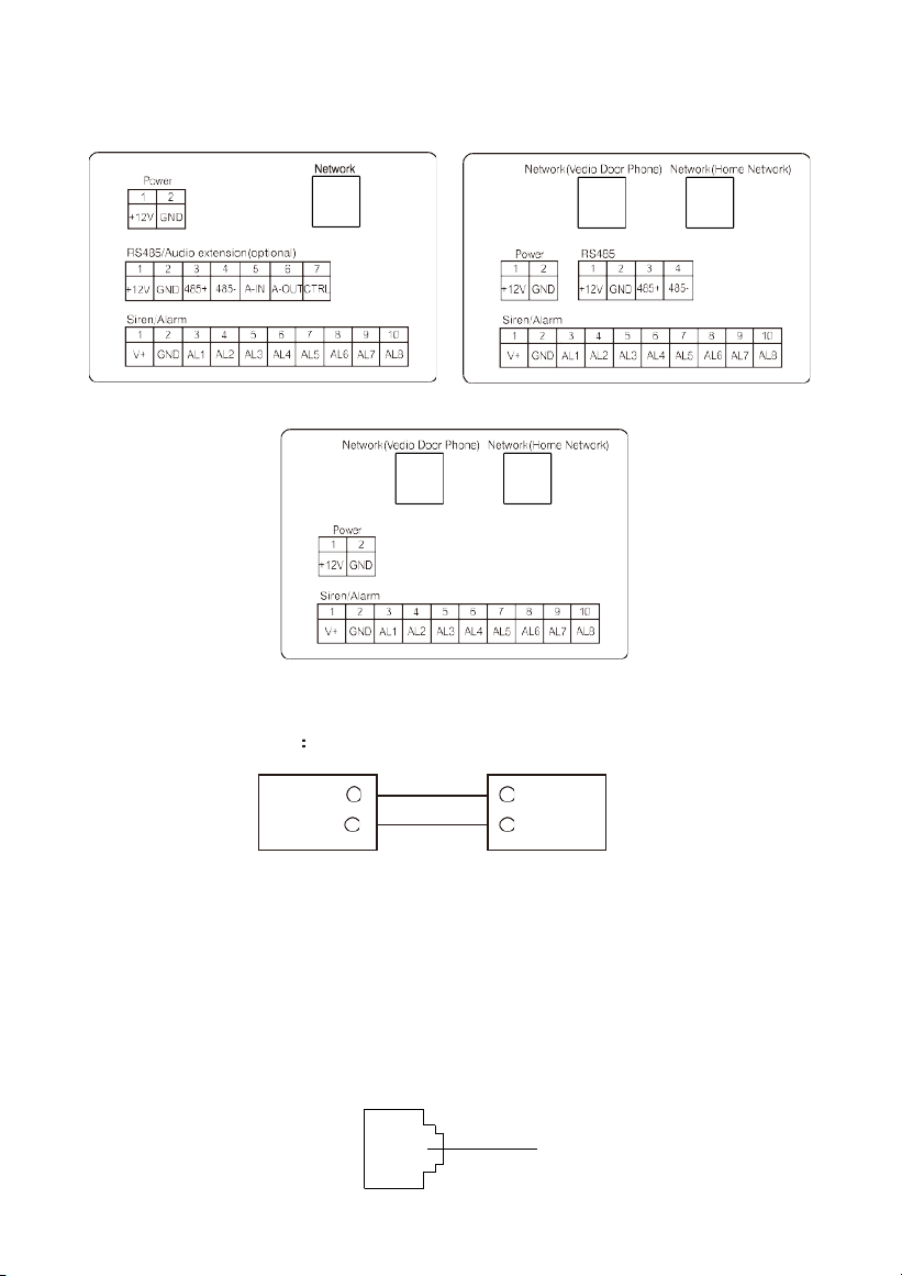
Standard Dual Ports
Dual Ports (Without RS485)
1. Power
Power input interface connect with 12V power adapter.
+12V
GND
+12V
GND
Power Interface
DC 12V
2 Network
Connect with outdoor panel, indoor monitor or other network equipment by network
switch.
When indoor monitor has POE function, the interface can supply power by connecting
with POE network switch. If network interface has 12V power supply, pin No. 4 and 5 of RJ45
interface should connect with +12V of power interface, and pin No. 7 and 8 should connect
with GND of power interface.
Network
-29-
+12V
GND
485+
485-
+12V
GND
485+
485-
+12V
GND
485+
485-
+12V
GND
485+
485-
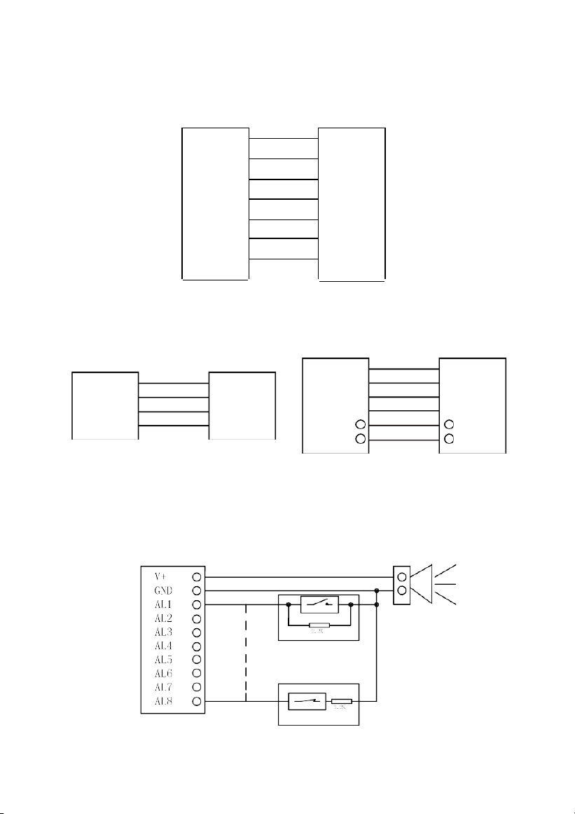
3. RS485/Audio extension
When there is audio extension, the audio extension interface and RS485 interface can be
connected to the audio extension.
+12V
+12V
GND
485+
485-
A_INT
A_OUT
CTRL
GND
485+
485-
A_INT
A_OUT
CTRL
RS485/Audio extension
Audio extension
4. RS485
5. Alarm interface
Interface of alarm zones connects with normally-open or normally-closed switch.
When the alarm zone is triggered, it will output 12V/100mA power.
Siren equipment
Normally-open sensor
Alarm
Normally-closed sensor
-30-
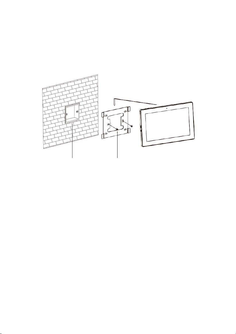
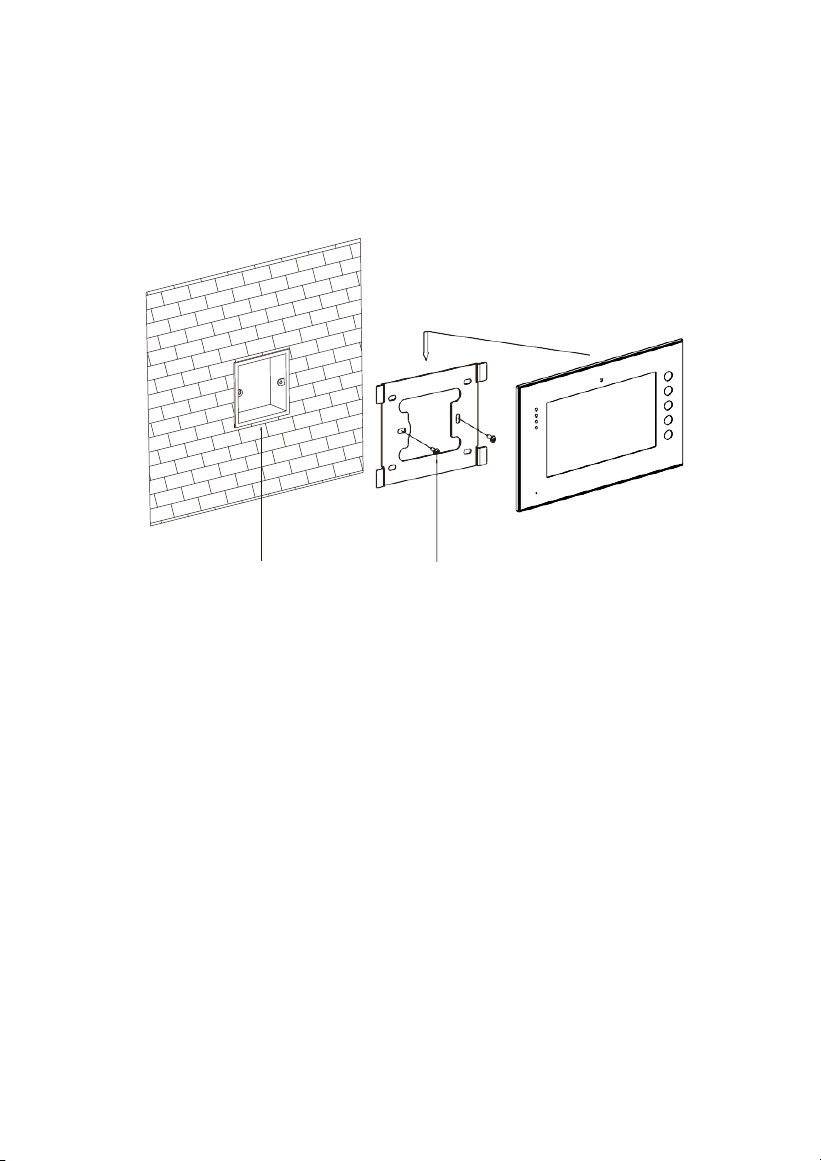
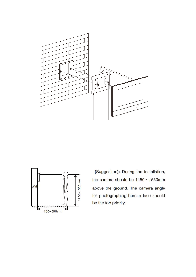
Installation
Model: VT10-B21A
Built-in box Screws
Size: 270*168*15mm
-31-
Model: VT07-B23A
Built-in box Screws
Size: 235*145*19.5mm
-32-
Built-in box Bracket
Screws
Model: VT07-B21A/VT07-B22A
Size: 221.4*151.4*16.5mm

-33-
Troubleshooting
The indoor monitor cannot start up or power off automatically.
Check whether it has power-failure, and power it on again.
The indoor monitor display screen is too dim.
Check whether the brightness and contrast settings of screen are
correct.
No sound during the communication.
Check whether the indoor monitor is set as mute mode, or the
volume is set to the lowest.
The indoor monitor cannot monitor the outdoor panel.
Other user is using the system, so you can use it once he/she
finished the operation.
Multimedia files cannot be played normally.
Check whether the system supports the file format. Please refer to
multimedia setting for details.
No response when clicking indoor monitor display screen.
Press “Unlock” button for 5s, or slowly slide horizontally or vertically on
the LCD to make touchscreen calibnation. It needs to be calibrated twice.
Touchscreen responses slowly or cannot make calibnation.
Take down any protective paster, since it may affect identification
and input for device;
Ensure the finger is dry and clean when clicking touchscreen;
Restart the device to clear any temporary software error.
The temperature of device is too high.
Long-term use leads to high temperature. It’s normal and will not
affect the device’s use life and performance.

-34-
Safety Precaution
In order to protect you and others from harm or your device from damage, please
read the following information before using the device.
Do not install the device in the following places:
Do not install the device in high-temperature and moist environment or the
area close to magnetic field, such as the electric generator, transformer or
magnet.
Do not place the device near the heating products such as electric heater or the
fluid container.
Do not place the device in the sunshine or near the heat source. This
might cause discoloration or deformation of the device.
Do not install the device in an unstable position to avoid the property losses or
personal injury caused by the falling of device.
Guard against electric shock, fire and explosion
Do not use damaged power cord, plug or loose outlet.
Do not touch the power cord with wet hands or unplug the power cord
by pulling.
Do not bend or damage the power
cord.
Do not touch the device with wet
hands.
Do not make the power supply slip or cause the impact.
Do not use the power supply without the manufacturer's
approval.
Do not have the liquids such as water go into the device.
Clean Device Surface
Clean the device surfaces with soft cloth dipped in some water, and then rub
the surface with dry cloth.
Other Tips
In order to prevent damage to the paint layer or the case, please do not
expose the device to chemical products, such as the diluent, gasoline,
alcohol, insect-resist agents, opacifying agent and insecticide.
Do not knock on the device with hard objects.
Do not press the screen surface. Overexertion might cause flopover or
damage to the device.
Please be careful when standing up from under the device.
Do not disassemble, repair or modify the device at your own discretion. The
arbitrary modification is not covered under warranty. When any repair
required, please contact the customer service center.
If there is abnormal sound, smell or fume in the device, please unplug
the power cord immediately and contact the customer service center.
When the device isn’t used for a long time, the adaptor and memory card can
be removed and placed in dry environment.
When moving, please hand over the manual to new tenant for proper usage
of the device.

-35-
Other notes
In order to prevent paintcoat or outer skin from damage, don’t make the device
contact with chemicals, such as diluent, gasoline, alcohol, insect-resist agents,
opacifier, insecticide, etc.
Don’t knock or beat the device with hard materials.
Don’t put pressure on display screen. Pressing too hard may lead to frame
stoppage or damage for the device.
If you are sitting under the device, please pay more attention when standing up.
Don’t disassemble, configure or fix the device by yourself. The manufacturer will
not guarantee for such change or configuration of device. To repair, please contact
customer service center.
If the device makes strange sound, taste or smoke, please unplug the power
supply immediately and contact customer service center in time.
If the device isn’t used for a long time, we suggest to unplug the power adapter and SD
card, and place it on the dry environment.
Please hand over the instruction to new owner for proper usage of the device.

-36-
ZKTeco Industrial Park, No. 32, Industrial Road,
Tangxia Town, Dongguan, China.
Phone : +86 769 - 82109991
Fax : +86 755 - 89602394
www.zkteco.com
Copyright © 2024 ZKTECO CO., LTD. All Rights Reserved.


