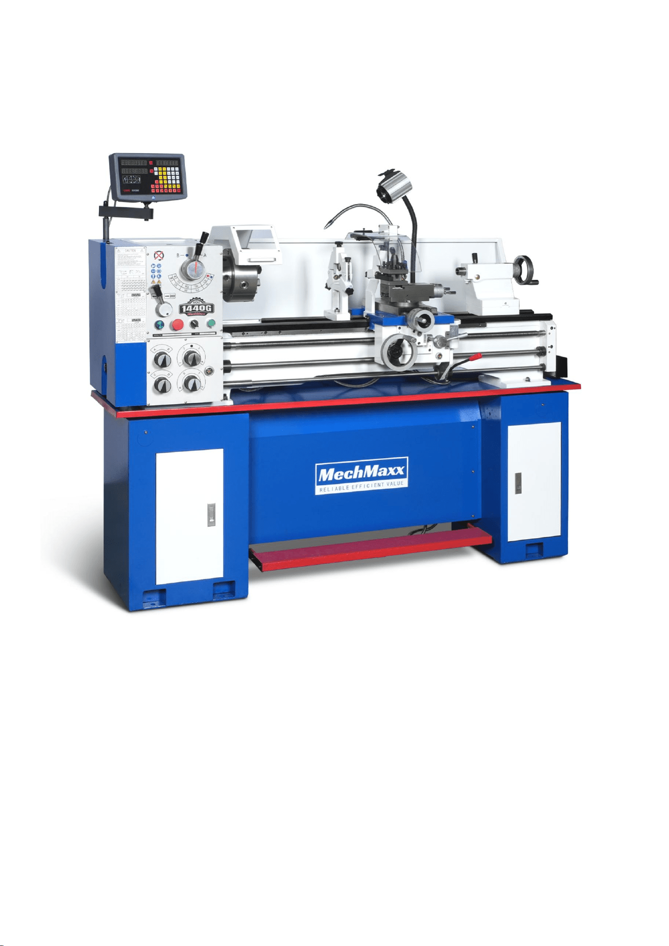
1340G METAL LATHE MACHINE
SKU:500013
MODEL:1340G

TABLE OF CONTENTS
1. SPECIFICATIONS
2. WARNING
3. INTRODUCTION
4. OPERATIONS
5. MAINTENANCE
6.
TROUBLESHOOTING
7.
COMPONENTS
8.
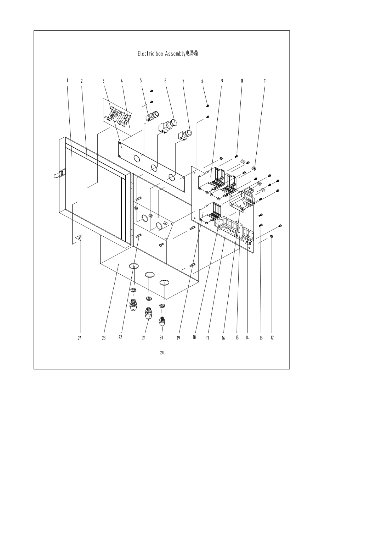
ELECTRICAL SCHEMATIC

1. SPECIFICATIONS
Item
Specification
Machine Model
1340G
Type
Metal Lathe
Swing Over Bed
13" (330 mm)
Swing Over Cross Slide
8-33/50" (220 mm)
Swing Through Gap
19-17/25" (500 mm)
Useful Gap Length
4-1/2" (115 mm)
Center Height
7" (178 mm)
Distance Between Centers
39-1/3" (1000 mm)
Bed Width
7-3/8" (187 mm)
Bed Length
65-1/3" (1658 mm)
Bed Height
11-13/32" (290 mm)
Main Motor
2 HP, 220V Single-Phase, 60Hz
Spindle Bore
1-1/4" (40 mm)
Spindle Nose
D1-4" ASA Standard (ISO)
Spindle Taper (in nose)
MT4
Number of Spindle Speeds
8 speeds
Spindle Speed Range
70–2000 RPM
Cross Slide Width
4-5/8" (118 mm)
Cross Slide Travel
6-5/16" (160 mm)
Toolpost Width
3" (76 mm)
Toolpost Travel
2-3/4" (70 mm)
Leadscrew Diameter
7/8" (22 mm)
Leadscrew Pitch
8 TPI or 3 mm
Feed Rod Diameter
3/4" (19 mm)
Max Cutting Tool Section
5/8" × 5/8" (16 × 16 mm)
Imperial Threads
34 pitches (4–56 TPI)
Metric Threads
26 pitches (0.25–7 mm)
Longitudinal Feed (Imperial)
32 choices (0.0020–0.0548 in./rev)
Longitudinal Feed (Metric)
32 choices (0.051–1.392 mm/rev)
Cross Feed (Imperial)
32 choices (0.0007–0.0187 in./rev)
Cross Feed (Metric)
32 choices (0.018–0.475 mm/rev)
Tailstock Quill Diameter
1-1/4" (32 mm)
Tailstock Quill Travel
3-3/4" (95 mm)
Tailstock Taper
MT3
Net Weight (with stand)
1276 lbs (580 kg)
Gross Weight (with stand)
1386 lbs (630 kg)

Item
Specification
Packing Size
75.6" × 29.9" × 29.9" (1920 × 760 × 760 mm)
2. WARNING
2.1 General Safety Rules for Power Tools
⚠ Important Notice
Operating the 1440G Lathe without adhering to the following safety rules may result in serious personal injury,
property damage, or death.
Before using the machine, carefully read and understand this manual. Retain this manual for future reference
and training of subsequent users.
Read and Understand the Manual: Familiarize yourself with all functions, controls, and potential
hazards before operating the lathe.
Work Area Safety:
o Keep the work area clean and well-lit.
o Do not operate power tools in explosive atmospheres (e.g., in the presence of flammable liquids,
gases, or dust).
o Keep children and unauthorized persons away from the work area.
Personal Safety:
o Always wear ANSI-approved safety glasses and a face shield.
o Avoid loose clothing, jewelry, gloves, and long hair that could be caught in moving parts.
o Maintain proper footing and balance at all times.
o Stay alert and operate the machine only when in proper physical and mental condition.
Tool and Machine Safety:
o Keep machine guards in place and in working condition.
o Remove all adjustment tools (such as chuck keys and wrenches) before starting the machine.
o Use clamps or a vise to secure workpieces whenever possible.
o Never force the machine; use it only for its intended purpose.
o Inspect the machine regularly for damaged parts. Repair or replace any damaged components
before use.
Electrical Safety:
o Use the machine only with a properly grounded 220V Single-Phase 60Hz electrical supply.

o Do not expose electrical components to moisture.
o Disconnect the machine from the power source before servicing or making adjustments.
o Ensure emergency stop buttons and main power switches are functional and easily accessible.
Preventative Measures:
o Use only accessories recommended by the manufacturer.
o Avoid accidental starting by ensuring the switch is OFF before plugging in.
o Never stand on the machine or use it as a platform.
o Never leave the machine running unattended. Always power off and wait for the spindle to
come to a complete stop.
2.2 Specific Safety Rules for 1440G Lathe
The 1440G Lathe incorporates moving mechanical components that can cause injury if used improperly. Special
attention must be given to the following areas:
2.2.1 General Safety Guidance
Always wear appropriate personal protective equipment (PPE), including safety glasses and hearing
protection.
Never operate the lathe if you are tired, distracted, or under the influence of drugs or alcohol.
Make sure all guards and covers are installed correctly before starting the lathe.
Secure the workpiece properly using the chuck, faceplate, or centers before beginning machining
operations.
2.2.2 Machine Safety
Never operate the lathe with missing or damaged guards.
Always remove the chuck key immediately after setting up a workpiece.
Feed workpieces against the spindle rotation direction.
Always allow the spindle to come to a full stop before changing speeds, adjusting the tool, or measuring
the workpiece.
When turning long workpieces, use the steady rest or follow rest for support.
Inspect cutting tools regularly; replace worn or damaged tools promptly.
2.2.3 Electrical Safety
Connect the machine only to a 220V Single-Phase 60Hz properly grounded power supply.
Use a dedicated electrical circuit protected by appropriate fuses or circuit breakers.
Ensure emergency stop devices are functional and tested regularly.
Disconnect power before performing any maintenance, adjustments, or when changing accessories.
Do not modify electrical components without authorization from a qualified technician.
2.2.4 Operational Safety
Inspect the lathe daily for signs of loose bolts, unusual wear, or misalignment.
Change spindle speeds only when the lathe is completely stopped.
Do not adjust the workpiece, tooling, or guards while the machine is running.
Use recommended cutting speeds and feeds appropriate for the material being machined.
After completing operations, clean the machine, disconnect the power supply, and return all controls to
their neutral positions
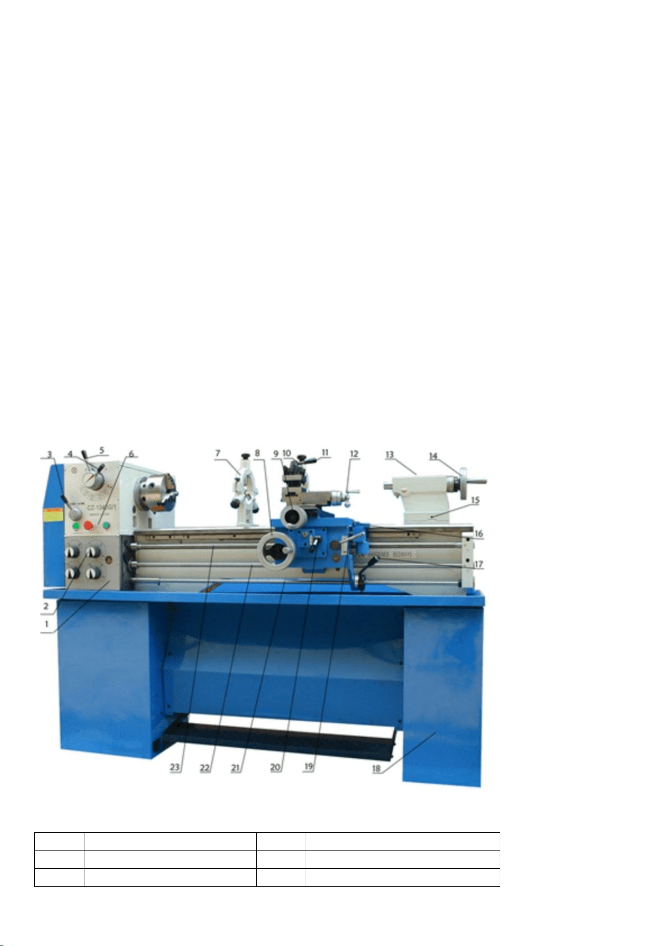
3. INTRODUCTION
3.1 Product Overview
The 1340G Bench Lathe is a versatile, high-performance machine designed for precision turning and threading
applications in a variety of settings, including machine shops, industrial environments, and hobbyist workshops.
This lathe is capable of handling a wide range of tasks, from basic turning operations to more complex
threading and cutting operations, making it an essential tool for machining metal parts.
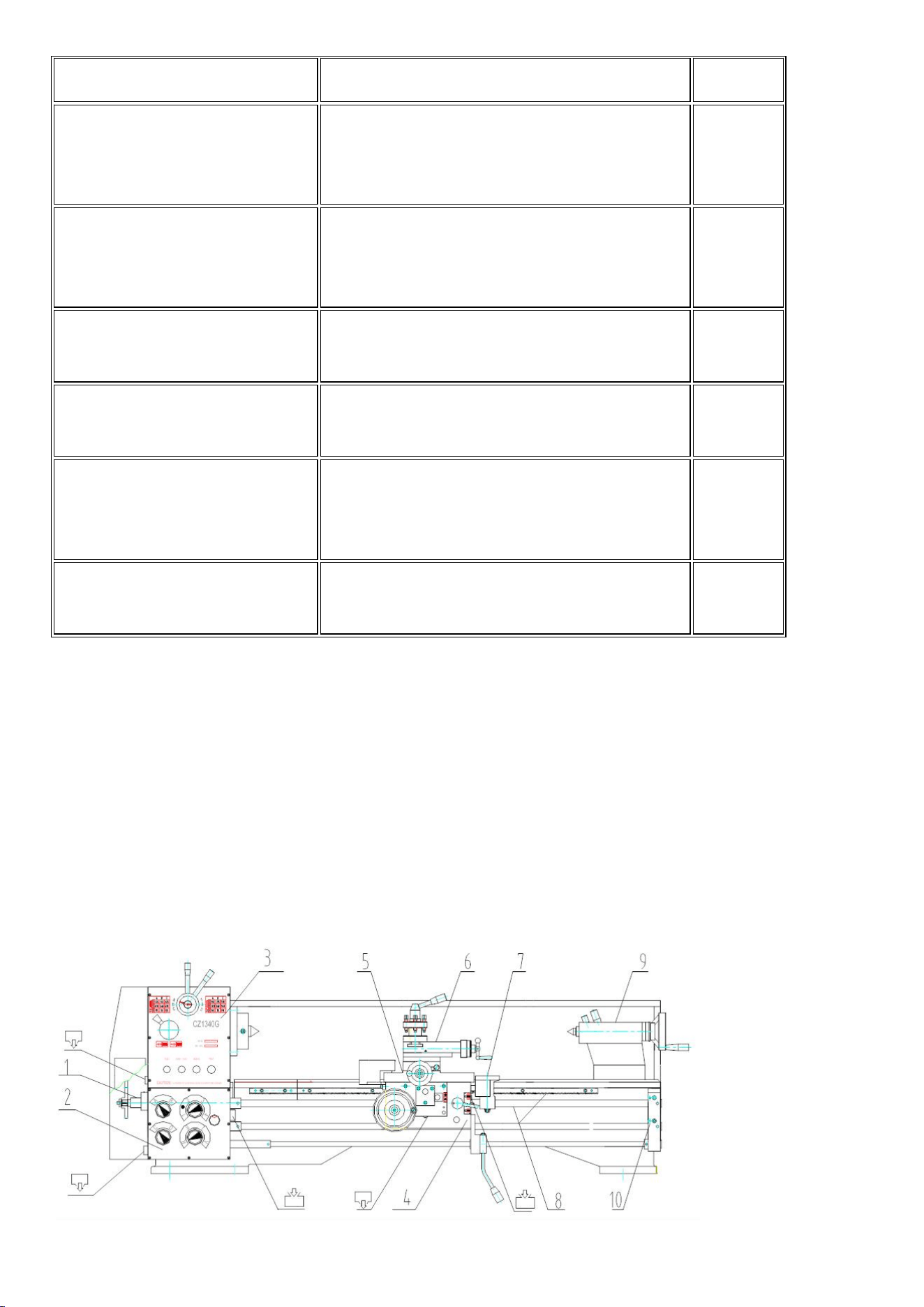
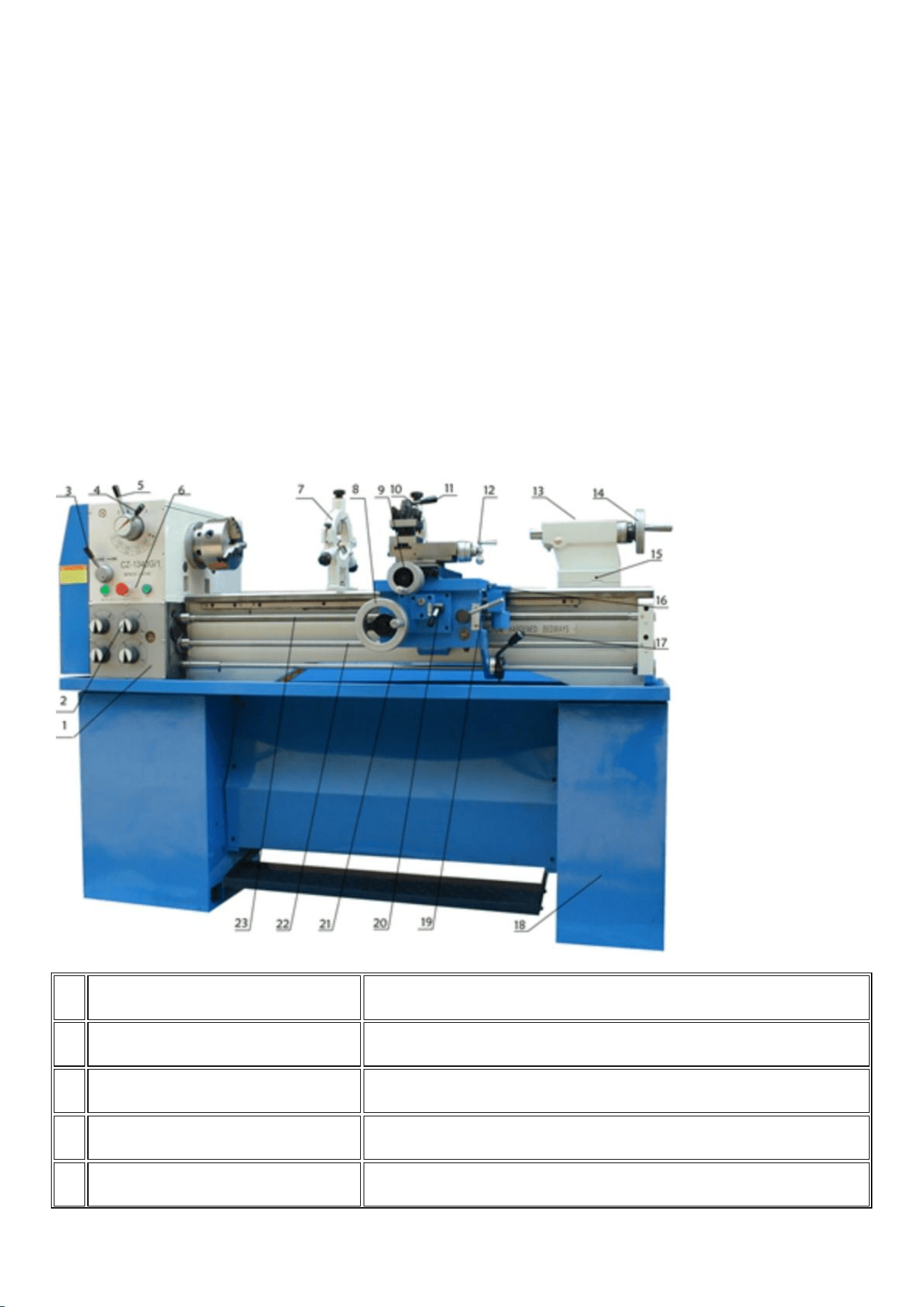
No.1
Component1
No.2
Component2
1
Forward/Reverse Switch
2
Handle
3
Feed Direction Selector
4
Four Steps Speed Selector

5
Low/High Speed Selector
6
Knob Component
7
Steady Rest
8
Longitudinal Traverse Hand
Wheel
9
Cross Traverse Hand Wheel
10
Follow Rest
11
Toolpost Handle
12
Toolpost Traverse Handle
13
Tailstock Quill Clamping
Lever
14
Tailstock Quill Traverse Hand
Wheel
15
Tailstock Set-Over Screw
16
Thread Dial Indicator
17
Controlling Lever
18
Machine Stand
19
Thread Cutting Engagement
Lever
20
Feed Axis Selector
21
Controlling Rod
22
Feed Rod
23
Lead Screw
3.2 Key Features
Heavy-duty Construction: Built with high-quality cast iron, the 1340G offers excellent rigidity and
stability, ensuring minimal vibration and high accuracy during operation.
Powerful Spindle: Equipped with an 8-speed spindle system, the lathe offers a wide range of speeds
from 70 to 2000 RPM, allowing it to handle a variety of materials and cutting operations with ease.
Versatile Threading: Capable of cutting both Inch and Metric threads, the 1340G provides a broad
range of threading options for different applications. The threading range spans from 4 to 56 TPI in
inch threads and 0.4 to 7 mm in metric threads.
Longitudinal and Cross Feed: The machine provides precise feed control, offering options for both
longitudinal and cross feed to meet the demands of turning, facing, and other operations.
Tailstock and Tool Post: The tailstock features a quill travel of up to 100 mm, while the tool post is
designed for secure and precise tool holding, ensuring optimal cutting performance.
3. INTRODUCTION
3.1 Product Overview
The 1340G Bench Lathe is a precision-engineered, heavy-duty machine tool designed for a wide range of
general-purpose metalworking tasks.
Built with a robust cast iron frame, precision-ground bedways, and versatile threading and feed capabilities, the
1440G offers the accuracy, strength, and reliability demanded by workshops, maintenance departments, and
small production facilities.
Its well-balanced design and ease of operation make it suitable for turning, facing, drilling, boring, and
threading a wide variety of workpieces, ranging from small precision parts to larger diameter shafts.
3.2 Key Features
Heavy-Duty Construction: The cast iron bed, headstock, and carriage components provide excellent

rigidity and vibration damping for precise machining.
Versatile Thread Cutting: Capable of cutting a wide range of both imperial and metric threads without
the need for additional conversion gears.
Large Capacity: Generous swing over bed and gap clearance allow machining of larger and longer
workpieces.
Wide Speed Range: Eight spindle speeds, easily selectable, offer flexibility for roughing, finishing, and
threading operations across different materials.
Smooth Power Feed: Consistent longitudinal and cross feeds provide better surface finishes and
reduce operator fatigue during extended operations.
Operator-Friendly Controls: Clear feed/threading charts, straightforward speed change mechanisms,
and ergonomic handwheels ensure intuitive machine operation.
Comprehensive Safety Features: Equipped with an emergency stop button, magnetic contactor, chuck
guard, and other built-in protections to enhance operator safety.
Centralized Lubrication Points: Simplified daily maintenance helps ensure long-term performance and
reduces machine wear.
3.3 Applications
The 1340G Lathe is suitable for a wide range of machining tasks, including:
Turning external and internal cylindrical surfaces.
Facing the ends of shafts, bushings, and sleeves.
Drilling and boring using the tailstock and appropriate attachments.
Cutting both imperial and metric threads with high precision.
Producing prototypes, repairing parts, and conducting small-batch production runs.
3.4 Advantages
Precision and Accuracy: Hardened and precision-ground bedways maintain high machining tolerances
over years of use.
Durability and Rigidity: Heavy-duty construction minimizes deformation under heavy cutting loads.
Operational Flexibility: A wide range of speeds, feeds, and threading options accommodate diverse
machining needs.
Ease of Use: Logical control layout, quick-change features, and comprehensive instructional labeling
make the lathe accessible to operators of varying skill levels.
Safety and Reliability: Built-in safeguards and dependable mechanical systems ensure a safer working
environment and reduce maintenance downtime.
4. OPERATIONS
4.1 Unpacking, Lifting, and Placement
4.1.1 Unpacking
Carefully remove the wooden crate and all packing materials.
Inspect the machine immediately after unpacking.
o Check for any visible damage during transport.
o If damage is found, report it to the carrier immediately and retain all packing materials for
inspection.
Locate the lathe using the lifting eyebolts attached to the machine bed. Ensure lifting is balanced to
avoid tilting.
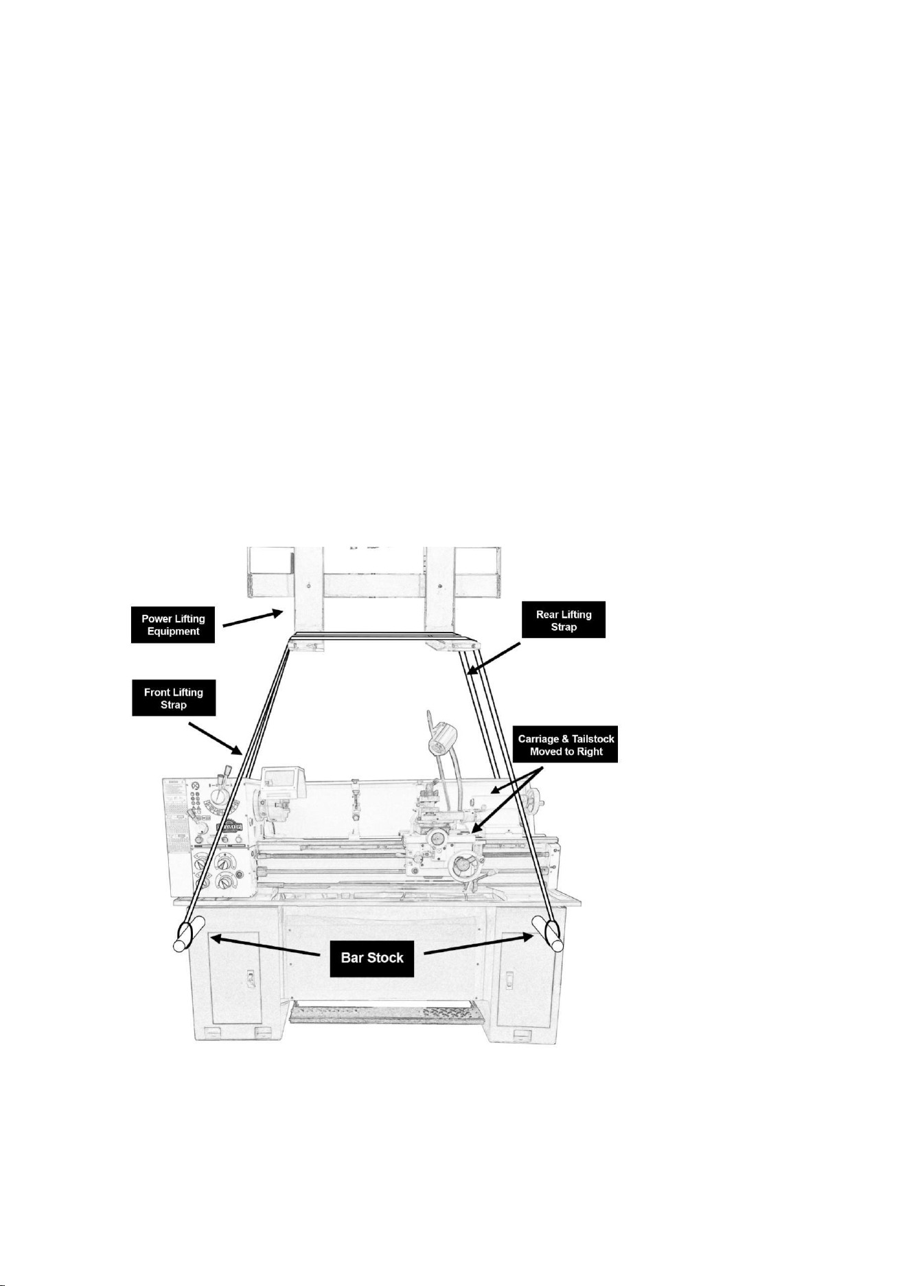
4.1.2 Lifting
Always use lifting straps or chains rated for the weight of the lathe (approximately 871 lbs / 395 kg net).
Position lifting devices carefully to avoid contacting the leadscrew, feed rod, spindle, or handwheels.
Maintain machine balance while lifting by adjusting the carriage and tailstock position as needed.
⚠ WARNING:
Do not lift the machine by chuck, spindle, feed rods, or any control levers.
Always ensure lifting points are properly secured before hoisting.

4.1.3 Placement
Install the lathe on a level, solid surface. A reinforced concrete floor is preferred.
Allow sufficient clearance around the machine for operation and maintenance. Recommended
minimum clearance:
o Rear: 18 inches (457 mm)
o Front: 24 inches (610 mm)
o Left/Right sides: 24 inches (610 mm)
If maximum precision is required, bolt the machine to the floor using four M12 anchor bolts through the
provided mounting holes.
After positioning, use a precision machinist's level placed across the bedways to ensure proper leveling.
Shim under the feet as needed to achieve perfect bed leveling. Improper leveling can lead to machining
inaccuracies.
4.2 Test Run Procedure
Before placing the 1440G lathe into regular service, it is critical to perform a complete test run to verify that the
machine has been installed correctly, is functioning properly, and is safe to operate.
The following procedure must be followed before cutting any materials:
4.2.1 Pre-Test Checklist
Ensure the machine is securely placed and leveled properly.
Verify that the machine is connected to a 220V Single-Phase 60Hz grounded power supply.
Confirm that all safety guards (chuck guard, belt cover, etc.) are installed and properly secured.
Check the lubrication oil levels in the headstock, apron, and other reservoirs.
Ensure that the emergency stop button and main power switch are functional.
4.2.2 Test Run Steps
Turn ON the main power switch.
Release the emergency stop button (if engaged).
Confirm that the Forward/Reverse Switch is in the neutral (OFF) position.
Start the spindle at the lowest speed setting.
Observe the spindle rotation for smoothness, vibration, or abnormal noises.
Switch the Feed Direction Selector and verify the feed axis changes appropriately without forcing.
Gradually increase spindle speeds through the gear ranges (low and high), pausing at each gear change

to:
o Listen for unusual sounds.
o Observe for excessive vibrations.
Test Forward and Reverse spindle rotation:
o Engage Forward rotation and verify smooth operation.
o Stop the spindle completely before engaging Reverse rotation.
Engage Manual Longitudinal Feed and Manual Cross Feed by rotating the respective handwheels.
Verify smooth movement.
Engage Power Feed using the feed rod:
o Select feed direction.
o Activate feed.
o Confirm feed movement is consistent and free from binding.
Test the Coolant Pump (if equipped):
o Turn ON the coolant switch and observe fluid flow from the nozzle.
o Turn OFF the coolant pump after checking.
4.2.3 Final Inspection
Verify that all handwheels and levers return to neutral positions smoothly.
Inspect the machine bedways and slides for any unusual signs of lubricant leakage or overheating.
Confirm that the emergency stop button will stop all operations immediately when pressed.
Power OFF the lathe after testing.
⚠ WARNING:
If any abnormal vibration, excessive noise, electrical failure, or mechanical binding is detected during the test
run, discontinue operation immediately. Investigate the cause and resolve the issue before continuing.
4.3 Spindle Operation
4.3.1 Starting the Spindle
Ensure that the Forward/Reverse Switch is in the neutral (OFF) position.
Confirm that the desired spindle speed is selected using the Four Steps Speed Selector and Low/High
Speed Selector (refer to Section 4.4).
Verify that the workpiece is securely mounted in the chuck or on the faceplate.

Release the emergency stop button if engaged.
Turn ON the main power switch.
Move the Forward/Reverse Switch to the Forward position for normal spindle rotation.
⚠ CAUTION:
Always make sure the spindle is at a complete stop before changing spindle speed or rotation direction.
4.3.2 Reversing the Spindle
Bring the spindle to a complete stop.
Move the Forward/Reverse Switch to the Reverse position.
Start the spindle in the reverse direction.
⚠ WARNING:
Reversing the spindle while rotating can cause mechanical damage or personal injury. Always stop the spindle
first.
4.3.3 Stopping the Spindle
Move the Forward/Reverse Switch back to the neutral (OFF) position.
The spindle will decelerate and come to a complete stop.
Always allow the spindle to stop naturally. Do not attempt to slow the spindle by hand.
4.3.4 Spindle Operation Safety Tips
Never leave the machine running unattended.
Avoid adjusting tooling or workpieces while the spindle is rotating.
Always use the emergency stop button in case of a malfunction.
Monitor spindle behavior during operation. If abnormal noise, vibration, or excessive heat is observed,
stop the machine immediately and investigate the cause.
4.4 Spindle Speed Selection
Proper spindle speed selection is essential for achieving the best machining results and prolonging tool life.
The 1440G lathe is equipped with a gearbox that provides 8 discrete spindle speeds, selectable through two
control levers: the Four Steps Speed Selector and the Low/High Speed Selector.
4.4.1 Speed Control Components
Four Steps Speed Selector:

o Used to select one of four basic speed settings within either the Low or High range.
Low/High Speed Selector:
o Used to toggle between the Low and High speed ranges.
Together, these selectors allow the operator to choose from eight spindle speed options between 70 and 2000
RPM.
4.4.2 Spindle Speed Selection Procedure
Ensure the spindle is completely stopped before changing speed settings.
Move the Four Steps Speed Selector to the desired setting (I, II, III, or IV) corresponding to the spindle
speed chart located on the machine.
Move the Low/High Speed Selector to either Low or High range as needed.
After selecting the desired speed, restart the spindle.
⚠ WARNING:
Changing speed while the spindle is rotating can cause severe damage to the gearbox.
4.4.3 Recommended Spindle Speeds
The optimal spindle speed depends on the material, tool type, and desired finish.
General guidelines include:
Material
Roughing Speed (RPM)
Finishing Speed (RPM)
Mild Steel
200–400
400–700
Aluminum
500–1000
800–1500
Brass
500–800
800–1400
Stainless Steel
100–300
300–500
Cast Iron
150–300
300–500
✅ Always refer to material machining handbooks for specific cutting speed recommendations based on tool
material (HSS, carbide, etc.)
4.4.4 Notes on Speed Adjustment
Select a lower spindle speed for roughing cuts and harder materials.
Use higher spindle speeds for finishing cuts and softer materials.
Monitor the workpiece and tool temperature during operation. Excessive heat may indicate an incorrect
spindle speed or feed rate.

Always verify that gear shifting levers are fully engaged to prevent gear damage.
4.5 Chuck Installation and Removal
Proper installation and removal of the chuck are essential for safe and accurate machining.
The 1440G lathe spindle is equipped with a D1-4 Camlock system, allowing for quick and secure mounting of
chucks and faceplates.
4.5.1 Chuck Installation
Ensure the spindle is completely stopped and the lathe is disconnected from the power source.
Thoroughly clean the spindle nose and the rear mounting surface of the chuck. Remove all dirt, grease,
or metal chips.
Align the chuck cam pins with the corresponding holes in the spindle nose.
Slide the chuck onto the spindle nose carefully. Support the weight of the chuck to prevent damage to
the spindle or cam pins.
Using the chuck wrench, rotate each camlock stud approximately 90 degrees clockwise to engage the
cams.
Check that all camlocks are engaged within the “locked” position marks (usually between 3 o’clock and
6 o’clock).
Confirm that the chuck is securely mounted by gently tapping around the circumference of the chuck
and verifying there is no movement.
⚠ CAUTION:
Never overtighten the camlock studs. Only tighten until firm locking is achieved. Excessive force can damage
the cam studs or the spindle.
4.5.2 Chuck Removal
Ensure the spindle is completely stopped and the lathe is disconnected from the power source.
Support the chuck securely to prevent it from falling during removal.
Rotate each camlock stud approximately 90 degrees counterclockwise to disengage the cams.
Carefully slide the chuck straight off the spindle nose. Avoid tilting or forcing the chuck to prevent
damage.
⚠ WARNING:
The chuck is heavy and may cause serious injury if dropped. Use appropriate lifting techniques or assistance
when handling large or heavy chucks.
4.5.3 Chuck Handling Tips
Always use two hands when mounting or removing the chuck.
If the chuck is too heavy, use an overhead hoist or lifting device with appropriate fixtures.

Inspect camlock studs regularly for wear or damage.
Keep all mating surfaces clean and lightly oiled to prevent rust and ensure proper seating.
4.6 Manual and Automatic Feed Operation
The 1440G lathe provides two methods for moving the cutting tool during machining:
Manual Feed — Controlled directly by the operator using handwheels.
Automatic Feed — Mechanically driven by the feed rod or leadscrew through the headstock gear
system.
Proper use of feed operations ensures machining efficiency, accuracy, and operator safety.
4.6.1 Manual Feed Operation
Manual feed is controlled directly by the operator using the handwheels:
Longitudinal Manual Feed (Carriage Movement Along Bed):
o Rotate the Longitudinal Traverse Handwheel to move the carriage left or right along the
bed.
Cross Manual Feed (Cross Slide Movement):
o Rotate the Cross Traverse Handwheel to move the cross slide toward or away from the
spindle centerline.
Manual feed is typically used during setup, fine adjustments, or when performing finishing passes.
4.6.2 Automatic Feed Operation
Automatic feed uses mechanical power transmitted through the feed rod or leadscrew to move the carriage or
cross-slide without manual handwheel input.
4.6.2.1 Longitudinal Automatic Feed (Using Feed Rod)
Start the spindle rotation.
Set the Feed Direction Selector to longitudinal feed.
Verify that the machine is set to use the feed rod for automatic feed.
Select the desired feed rate by adjusting the gearbox levers according to the feed chart.
Engage the Controlling Lever to begin automatic carriage movement along the bed.
This method is used for external cylindrical turning operations.
4.6.2.2 Cross Automatic Feed (Using Feed Rod)
Start the spindle.

Set the Feed Direction Selector to cross feed.
Confirm that the feed rod is selected, not the leadscrew.
Engage the Controlling Lever to start automatic cross-slide movement.
This method is used for facing operations.
4.6.3 Switching Between Longitudinal and Cross Automatic Feed
The Feed Axis Selector Lever located on the carriage apron allows the operator to switch between
longitudinal and cross feed modes.
Always disengage automatic feed before operating the selector lever.
Feed Axis Selector Positions:
Cross Feed Engaged (Lever Up):
Cross-slide automatically moves toward or away from the spindle axis.
Feed Disengaged (Neutral Position):
No automatic feed movement is engaged.
Longitudinal Feed Engaged (Lever Down):
Carriage automatically moves left or right along the bed.
⚠ WARNING:
Switching feed direction while the automatic feed is engaged can cause internal gear damage.
4.6.4 Feed Mechanism Selection Overview
The 1440G lathe uses two mechanical systems for feeding:
Feeding (Automatic Feed via Feed Rod):
Standard turning, facing, and general operations.
Powered by the feed rod.
Carriage or cross-slide moves automatically without manual handwheel rotation.
Threading (Lead Screw Feed):
Dedicated to synchronized thread cutting.
Powered by the leadscrew.
Requires engagement of the half-nut lever to synchronize carriage movement with spindle
rotation.
Feed and Threading Mechanism Illustration
Feeding (left figure)
Threading (right figure)
4.6.5 Safety Considerations During Feed Operations
Never operate handwheels manually while automatic feed is engaged.
Always start spindle rotation before engaging automatic feed.
Disengage automatic feed before changing feed direction.
Monitor tool movement carefully to prevent collisions with the chuck or workpiece ends.
When performing thread cutting, follow proper half-nut engagement procedures and synchronize
using the thread dial indicator (for imperial threads).
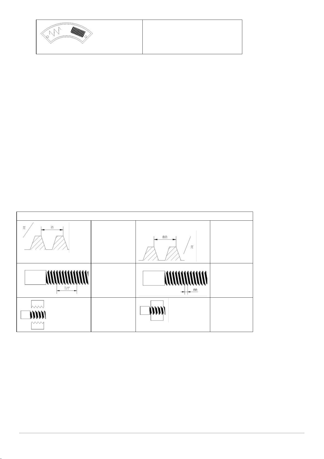
4.7 Thread Cutting Operation
The 1340G lathe is equipped to cut a wide variety of imperial (inch) and metric threads.
Proper setup and execution are critical to producing accurate, high-quality threads.
Thread Type Symbols
Diametral
pitch thread
item
Module pitch
thread
Imperial
thread
Metric thread
Half nut
opened
Half nut
closed
4.7.1 General Thread Cutting Principles
Threads are cut by synchronizing the movement of the carriage with the rotation of the spindle using
the leadscrew.
The carriage advances in exact proportion to the spindle's rotation, allowing the cutting tool to trace a
helical path along the workpiece.
During threading operations, manual feed and automatic feed (via feed rod) are disabled; only
leadscrew-driven movement is used.

4.7.2 Setup for Thread Cutting
Select the Desired Thread Type:
o Imperial threads (4–56 TPI) or Metric threads (0.25–7 mm).
Adjust the Gearbox Levers:
o Refer to the Thread Chart on the machine to set the correct combinations of levers (A, B, C, D)
for the selected thread pitch.
Engage the Leadscrew:
o Shift the transmission lever to select leadscrew drive instead of feed rod.
4.7.3 Preparing the Machine
Mount the workpiece securely in the chuck or between centers.
Install a sharp threading tool in the toolpost and align it square to the workpiece axis using a thread
gauge or machinist's square.
Set the compound rest at a 29° angle (for imperial 60° threads) to facilitate proper cutting and chip flow.
Adjust spindle speed:
o Use lower speeds (typically 70–200 RPM) to allow better control during threading.
4.7.4 Threading Procedure
Start the spindle.
Set the carriage close to the starting point of the thread.
Observe the Thread Dial Indicator for imperial threads:
o Engage the Half-Nut Lever at appropriate marks (typically numbered or evenly spaced) when
the dial aligns.
For metric threads:
o Keep the half-nuts engaged throughout the entire threading operation. Do not disengage
between passes.
The carriage will now move in synchronization with spindle rotation, cutting the thread.
After completing a pass:
o Disengage the spindle, back the tool out slightly using the cross-slide handwheel.
o Return the carriage to the starting point without disengaging half-nuts (for metric threads) or by
retracting for imperial threads.
o Adjust the compound rest inward slightly to increase cutting depth for the next pass.
Repeat the process until the desired thread depth is achieved.
4.7.5 Important Notes
Use cutting fluid as needed to improve finish and tool life, especially on difficult materials like stainless
steel.
Keep hands clear of moving parts at all times.
Always verify thread pitch and thread form after cutting by using thread gauges or fitting the mating
part.
Never change spindle speed or engage/disengage half-nuts while the spindle is rotating.
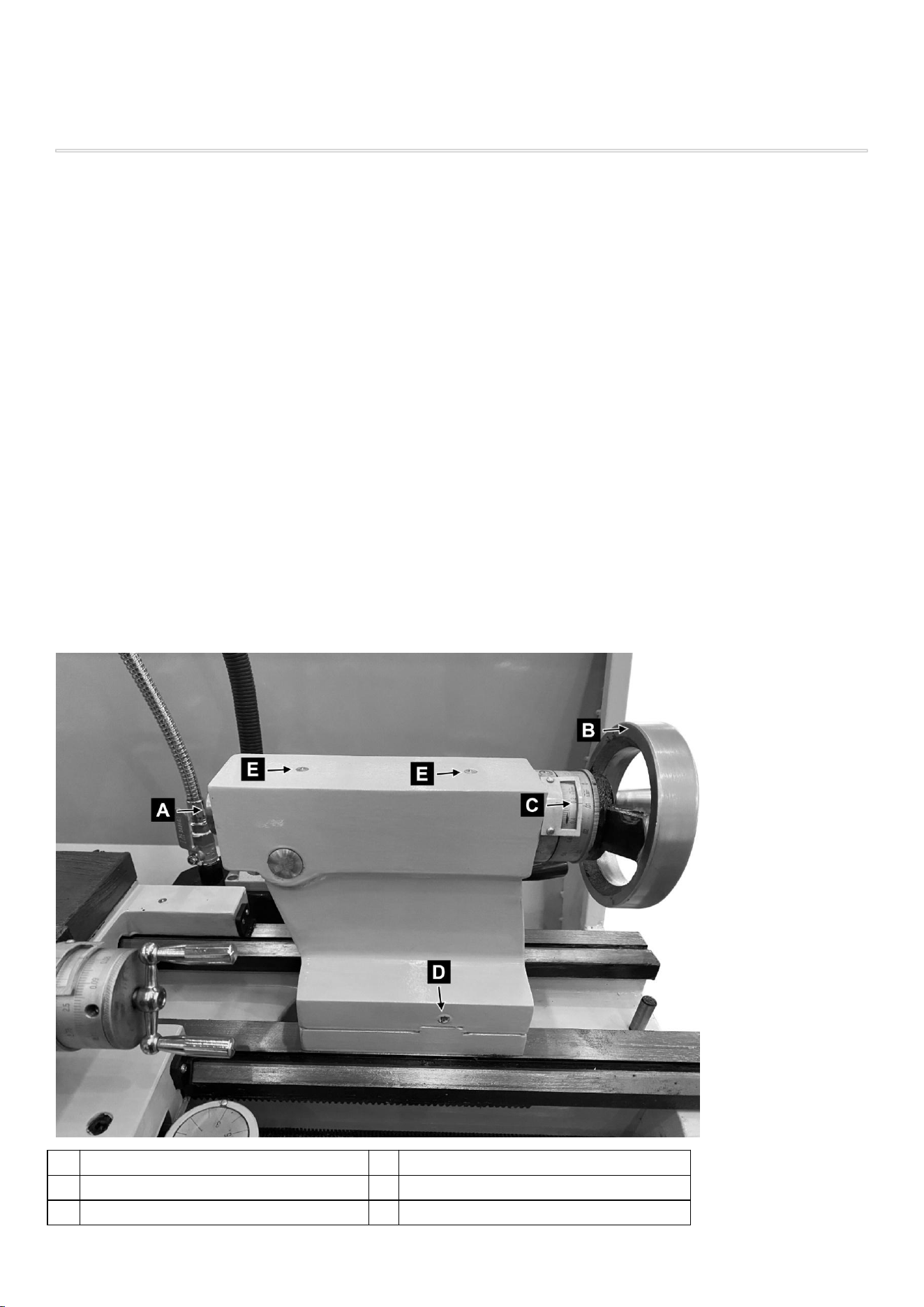
4.8 Tailstock Operation
The tailstock is an essential component of the lathe, designed to support long workpieces, hold tooling for
drilling and reaming, and enable taper turning through lateral adjustment.
Proper use of the tailstock increases machining accuracy, stability, and versatility.
4.8.1 Tailstock Components
A
Drift Slot
B
Quill Handwheel
C
Graduated Scale
D
Tailstock Offset Screws:
E
Tailstock ball oilers

Key components of the 1340G lathe tailstock include:
Tailstock Body: Slides along the lathe bed and houses all tailstock mechanisms.
Tailstock Quill (Ram): Moves forward and backward to engage tools like drill chucks or live centers.
Tailstock Quill Handwheel: Controls extension and retraction of the quill.
Tailstock Quill Clamping Lever: Locks the quill at a desired extended position.
Tailstock Base Clamp: Locks the entire tailstock body to the lathe bed.
Tailstock Set-Over Screws: Allow minor lateral offset of the tailstock for taper turning.
4.8.2 Moving and Locking the Tailstock
Loosen the Tailstock Base Clamp to slide the tailstock along the bed to the desired position.
Position the tailstock close to the workpiece or drilling point.
Re-tighten the base clamp to secure the tailstock firmly before machining.
⚠ WARNING:
Never operate the lathe while the tailstock is unlocked. Movement during operation can cause serious damage
or misalignment.
4.8.3 Extending and Retracting the Quill
Rotate the Tailstock Quill Handwheel clockwise to extend the quill forward.
Rotate it counterclockwise to retract the quill.
Use the Tailstock Quill Clamping Lever to lock the quill once it's in the proper position.
The quill travel should be sufficient for most drilling and reaming operations. When more travel is needed,
reposition the entire tailstock.
4.8.4 Installing Tailstock Tooling
The tailstock quill accepts standard MT3 taper-shank tools, including:
Live centers
Drill chucks with MT3 arbors
Reamers
Boring bars
To install:

Clean the tool shank and quill taper bore.
Insert the tool into the quill with a firm push to seat the taper.
No additional locking is needed due to the self-holding Morse taper fit.
To remove:
Fully retract the quill by turning the handwheel counterclockwise.
The internal ejector will automatically push out the tool.
4.8.5 Tailstock Set-Over for Taper Turning
The tailstock can be laterally offset to allow taper turning between centers.
To perform set-over adjustment:
Loosen the tailstock mounting bolts.
Turn the Tailstock Set-Over Screws (Item 15) left or right to shift the tailstock body slightly.
Use a dial indicator to measure taper offset, or refer to the desired taper per unit length.
After adjusting, tighten all mounting bolts securely.
NOTE:
Tailstock set-over is ideal for long, shallow tapers. For short or steep tapers, use the compound rest at an angle.
4.8.6 Typical Tailstock Applications
Application
Description
Center Drilling
Holding a drill chuck in the tailstock to start holes at the end of shafts.
Drilling/Reaming
Machining internal features using tailstock-mounted tools.
Taper Turning
Producing shallow tapers between centers via tailstock offset.
Work Support
Supporting long workpieces with a live or dead center to reduce deflection.
Boring
Using a boring bar in the tailstock for axial internal cuts (limited cases).
4.9 Coolant System Operation
The 1340G lathe is equipped with a recirculating coolant system to improve cutting performance, extend tool
life, and enhance surface finish.
Proper use of the coolant system is important during prolonged cutting operations, especially when working
with hard materials or deep cuts.

4.9.1 Coolant System Components
Coolant Pump: Electric pump located in the base or cabinet of the lathe, supplies cutting fluid to the
work area.
Coolant Reservoir: Integrated tank that holds coolant fluid, typically located beneath the machine.
Flexible Coolant Hose / Nozzle: Directs the coolant flow to the cutting area.
Coolant Control Valve: Located near the nozzle; allows manual control of flow volume or shutoff.
Coolant Switch: On/off switch mounted on the control panel or lathe apron to activate the pump.
4.9.2 Operating the Coolant System
1. Fill the Reservoir
o Open the access panel and fill the reservoir with the appropriate cutting fluid.
o Ensure the coolant level is above the pump intake.
2. Start the Coolant Pump
o Turn ON the Coolant Switch.
o Open the Coolant Control Valve to direct coolant to the cutting zone.
3. Adjust Coolant Flow
o Use the control valve or nozzle position to aim coolant toward the tool tip and cutting edge.
o Adjust the volume to ensure adequate coverage without excessive spray.
4. Stop the Coolant System
o Close the control valve.
o Turn OFF the coolant pump switch.
4.9.3 Coolant Maintenance
Check coolant level regularly and top off as needed.
Clean the reservoir and filter screens periodically to prevent clogging or pump damage.
Replace contaminated coolant if it becomes foul-smelling, discolored, or foamy.
4.9.4 Safety Precautions
Use only approved water-soluble coolant or cutting oil recommended by the manufacturer.
Always wear protective eyewear to avoid coolant spray.
Do not operate the coolant pump without sufficient fluid in the tank — running dry may damage the pump.

Disconnect power before cleaning or servicing coolant components.
4.10 Emergency Stop and Shutdown Procedure
4.10.1 Emergency Stop Procedure
The Emergency Stop Button is a large red pushbutton typically located on the lathe’s control panel or
apron.
It is designed to immediately cut off all power to the machine in case of danger or malfunction.
To perform an emergency stop:
1. Press the Emergency Stop Button firmly.
o This will instantly shut off spindle rotation, feed movement, and coolant flow.
2. Step away from the machine if needed.
o Ensure the operator and others are safe.
3. Investigate the cause of the emergency.
o Do not reset or restart the lathe until the issue has been clearly identified and resolved.
⚠ WARNING:
Do not use the emergency stop as a substitute for normal shut-off procedures.
4.10.2 Restarting After Emergency Stop
To resume operation after an emergency stop:
1. Clear any obstructions and verify safety.
2. Release the Emergency Stop Button by rotating it (typically clockwise) until it pops out.
3. Recheck spindle switch, feed direction selector, and coolant settings.
4. Power on the machine using the main power switch.
5. Resume normal operation cautiously.
4.10.3 Normal Shutdown Procedure
At the end of each machining session, follow these steps to shut down the lathe safely:
1. Turn off spindle rotation using the spindle switch or power button.
2. Disengage automatic feed by returning the Controlling Lever (Item 17) to neutral.
3. Turn off the coolant system, if used.
4. Return the carriage and cross-slide to a neutral or parked position.
5. Retract the tailstock quill and lock all moving parts.

6. Turn off the main power switch.
7. Clean the lathe bed and work area of chips, coolant, and oil.
4.10.4 Power Disconnection
If the machine will not be used for an extended period:
o Turn off the main circuit breaker or unplug the machine (if applicable).
o Lockout/tagout procedures should be followed in commercial or educational
environments.
4.10.5 Safety Reminders
· Never leave the lathe running unattended.
· Always remove the chuck key immediately after use.
· Ensure all guards are closed before restart.
· After emergency stops or abnormal conditions, perform a full machine check before resuming work.
5. MAINTENANCE
- Perform Maintenance Regularly
Establish a routine maintenance schedule. Frequent light maintenance is more effective than infrequent
major repairs.
- Always Disconnect Power Before Maintenance
To prevent accidental startup, turn off and unplug the machine (or disconnect from main power) before
performing any maintenance or inspection tasks.
- Use Appropriate Cleaning and Lubrication Products
Only use cleaners, lubricants, and coolants recommended for machine tools. Avoid using solvents that
may damage painted surfaces, electrical components, or seals.
- Keep the Machine Clean and Free of Chips
Metal shavings and debris can accelerate wear and interfere with moving parts. Brush or vacuum chips
regularly, especially from the ways, lead screw, and feed rod.
- Inspect Key Components Periodically
Regularly check belts, lead screws, feed rods, coolant system, wiring, and safety guards for wear or
damage.
- Monitor Lubrication Levels
Ensure that all lubrication points receive sufficient oil or grease according to the lubrication schedule.
Lack of lubrication is a major cause of machine wear and premature failure.
- Operate the Machine Correctly

Avoid abusive operation such as forcing cuts beyond machine capacity, operating without lubrication, or
overloading spindle bearings.
- Address Problems Promptly
If abnormal noise, vibration, oil leakage, or operational difficulties are detected, stop the machine
immediately and correct the issue before resuming operation.
5.2 Daily Maintenance Checklist
Performing a quick but thorough inspection and cleaning at the beginning and end of each workday will
significantly extend the life of the lathe and maintain safe operation.
Check Item
Task
Yes/No
1. Machine Exterior
Wipe down all accessible surfaces to remove
dust, chips, coolant residue, and oil.
2. Bedways and Slides
Remove metal shavings and apply a light coating
of way oil to prevent corrosion and ensure
smooth movement.
3. Lead Screw and Feed Rod
Clean off chips and apply a light coating of
lubrication if necessary.
4. Tailstock and Toolpost
Inspect for proper clamping and locking; check
for debris between mating surfaces.
5. Coolant System (if equipped)
Check coolant level; top off if needed. Check for
leaks.
6. Electrical Controls
Visually inspect switches, cables, and emergency
stop for any signs of damage or wear.
7. Safety Guards
Ensure all guards and shields are in place,
functional, and properly secured.
8. Lubrication Points
Verify lubrication in headstock, carriage,
leadscrew (if equipped with oil reservoirs). Top
up if low.
9. Chucks and Workholding Devices
Clean jaws, remove chips, and verify secure
mounting.
10. General Area
Sweep or vacuum around the lathe. Remove
excess oil or coolant spills from the floor to
prevent slipping.

· Time Requirement:
A full daily inspection should take approximately 10–15 minutes.
· Tools Needed:
Clean rags, chip brush, way oil, general-purpose lubricant, flashlight.
· Benefits:
Regular daily maintenance helps detect small problems before they become major failures, maintains
cutting accuracy, and ensures workplace safety.
5.3.1 Weekly Maintenance Tasks
Perform the following once every week (or approximately every 40 operating hours):
Check Item
Task
1. Carriage
Movement
Check for smooth travel. Clean ways, leadscrew, and feed rod thoroughly. Re-oil
bedways.
2. Gearbox Oil Check
Inspect oil level (if applicable) and top up using recommended oil.
3. Tailstock
Clamping
Check and adjust tailstock clamp tension if necessary.
4. Chuck Inspection
Remove the chuck if necessary; clean mounting surfaces and camlock studs (for
D1-4 spindle).
5. Coolant System
Inspect hoses, pump, and fittings for leaks or clogging. Flush if necessary.
6. Toolpost
Inspection
Inspect toolpost and tool holder for wear, proper locking, and debris under contact
areas.
7. Safety Features
Test emergency stop function, door interlocks (if equipped), and coolant shut-off.
5.3.2 Monthly Maintenance Tasks
Perform the following once every month (or approximately every 160 operating hours):
Check Item
Task
Yes/No
1. Headstock Oil Change
Drain and replace headstock oil according to
lubrication schedule.
2. Apron and Gearbox Oil Change
If applicable, change apron and/or gearbox oil.
Check Item
Task
Yes/No
3. Lead Screw Inspection
Inspect the entire lead screw for signs of wear,
misalignment, or damage. Lubricate
thoroughly.
4. Electrical Connections
Inspect and tighten all visible electrical
connections inside control panels. Check for
burnt smells or discoloration.
5. Drive Belts and Pulleys
Inspect for cracks, fraying, or slack. Adjust belt
tension if necessary.
6. Way Wipers
Inspect and replace worn way wipers on
carriage and cross-slide.
7. Gibs Adjustment
Check and adjust gibs (on carriage, cross slide,
compound rest) for smooth, backlash-free
movement.
8. Clean Coolant Tank
Drain and clean the coolant reservoir; replace
old coolant if dirty or contaminated.
Log all maintenance activities if operating in a commercial shop or educational facility.
Use a proper maintenance logbook for audits and long-term record keeping.
5.4 Lubrication Points and Schedule
Proper lubrication is essential to minimize wear, maintain machining accuracy, and extend the service life
of the lathe.
The following guidelines specify the recommended lubrication points, oil types, and service intervals for
the 1440G lathe.
5.4.1 Recommended Lubricants

No.
Lubrication Part
Number of
Lubricating Points
Oil Type
Frequency of
Lubrication
Oil Change Interval
1
Input Shaft of
Gearbox
1
ISO 68
Machine Oil
Daily
—
2
Gearbox
1
ISO 68
Machine Oil
—
First change after 3
months, then once per year
3
Headstock
1
ISO 68
Machine Oil
Weekly
Inspection
—
4
Apron
1
ISO 32
Machine Oil
Weekly
Inspection
—
5
Carriage
5
ISO 32
Machine Oil
Daily
—
6
Tool Post
3
ISO 32
Machine Oil
Daily
—
7
Thread Dial
Indicator
1
ISO 32
Machine Oil
Daily (Light
application)
—
8
Leadscrew and
Feed Rod
2
ISO 32
Machine Oil
Daily
—
9
Tailstock
3
ISO 32
Machine Oil
Daily
—
10
Support Seat
2
ISO 32
Machine Oil
Daily
—
5.4.2 Lubrication Tips
Do not over-lubricate.
Excess oil can attract dust and chips, leading to premature wear.
Always clean before lubricating.
Remove old grease, chips, and metal debris from surfaces.
Use proper oiling equipment.
Apply with precision oilers or grease guns designed for machine tools.
Monitor oil quality.
Change oils if they appear dirty, milky, or contaminated.

5.5 Coolant System Maintenance
The coolant system must be properly maintained to ensure efficient cutting performance, extend tool life,
and prevent contamination that could damage the machine or create health hazards.
5.5.1 Daily Coolant System Checks
At the start and end of each workday:
Check Coolant Level
Ensure the coolant reservoir contains an adequate amount of clean coolant. Top off if necessary.
Inspect Coolant Quality
Look for signs of coolant degradation, such as odor, discoloration, or excessive foaming.
Check Hoses and Connections
Inspect for leaks, cracks, or loose fittings in hoses and nozzles.
Ensure Proper Flow
Verify that the coolant flows properly from the nozzle when activated. Adjust nozzle aim if
needed.
5.5.2 Weekly Coolant Maintenance
Once per week:
Flush Nozzle and Lines
Spray clean water (if appropriate) or fresh coolant through the lines to prevent clogging.
Clean Nozzles and Filters
Remove any chips, debris, or dried coolant from nozzle tips and screen filters.
Inspect Coolant Pump
Listen for unusual noises indicating pump wear. Check that the pump delivers a steady flow.
5.5.3 Monthly Coolant System Service
Once per month or as needed:
Drain and Clean the Coolant Tank
Completely drain the coolant reservoir. Remove sludge, metal chips, and biological growth from
the tank walls and bottom.
Refill with Fresh Coolant
Mix new coolant according to manufacturer instructions. Do not reuse old contaminated coolant.
Inspect Pump and Electrical Connections
Ensure the coolant pump is secure, the power wiring is intact, and all connections are free from
corrosion.

5.5.4 Coolant Fluid Management Tips
Use Only Approved Coolants
Water-soluble coolants specifically designed for machine tools are recommended. Follow mixture
ratios provided by the coolant manufacturer.
Maintain Correct Concentration
Use a refractometer to monitor coolant concentration and adjust as necessary.
Prevent Biological Growth
Avoid stagnation by circulating coolant regularly. Add biocides if needed according to coolant
supplier recommendations.
Dispose of Waste Coolant Properly
Follow local regulations for disposal. Never pour used coolant into drains without proper
treatment.
5.6 Cleaning Instructions
Regular cleaning of the lathe is critical to maintaining machining precision, reducing wear, and ensuring
safe operation.
Accumulated chips, coolant residue, and oil buildup can cause mechanical issues and hazardous working
conditions if not removed properly.
5.6.1 Daily Cleaning Tasks
At the end of each workday or machining session:
Remove Chips and Debris
o Use a chip brush or vacuum to remove chips from the bedways, cross-slide, carriage, and
leadscrew.
o Never use compressed air to blow chips near bearings or electrical components — it can
force debris into sensitive areas.
Wipe Down Surfaces
o Use clean, dry rags to wipe down exposed metal surfaces.
o Apply a thin coat of way oil to bedways and other sliding surfaces to prevent rust.
Clean the Toolpost and Tailstock
o Remove accumulated debris from under the tool holders and tailstock base.
Clean Around the Chuck
o Brush away chips around the chuck and faceplate.
o Inspect jaws for chips trapped between workpieces and chuck faces.
5.6.2 Weekly Cleaning Tasks
Clean and Inspect the Chuck or Faceplate

o Remove the chuck if necessary and clean mounting surfaces and camlock studs.
o Lightly oil the contact surfaces to prevent rust.
Inspect and Clean Coolant System Components
o Clean coolant nozzles, hoses, and filters.
o Wipe down the coolant tank surface if accessible without full draining.
Check for Oil Leaks or Coolant Drips
o Wipe up any standing oil or coolant from the machine and floor area.
5.6.3 Monthly Deep Cleaning
Full Coolant Tank Service
o Drain, scrub, and refill the coolant tank (see Section 5.5).
Lead Screw and Feed Rod Cleaning
o Wipe clean the full length of the lead screw and feed rod.
o Reapply light machine oil after cleaning.
Electrical Enclosure Cleaning
o If accessible and safe, gently wipe dust buildup on control panel exteriors using a dry cloth.
o Do not open or tamper with internal electrical components unless qualified.
6.
TROUBLESHOOTING
Accurate diagnosis and timely corrective action can prevent machine damage and reduce downtime.
6.1 General Troubleshooting Guidelines
Step 1: Ensure Power is Properly Connected
Verify that the machine is plugged in or connected to the facility's power source.
Check that the main power switch, emergency stop button, and control switches are in their
correct positions.
Cleaning Tips
Use only non-abrasive brushes to avoid scratching precision surfaces.
Do not flood electrical components with water or coolant.
Immediately clean up spills to prevent slips and corrosion.
Apply anti-rust oil or way oil after cleaning all bare metal surfaces.

Reset the emergency stop button if it was previously engaged.
Step 2: Check for Loose or Improper Settings
Confirm that all clamps, knobs, and levers are securely engaged.
Inspect the gearbox levers, feed direction selector, and feed axis selector for correct positions.
Ensure that the chuck is properly tightened and the tailstock is locked if in use.
Step 3: Look for Obstructions or Debris
Remove any chips, swarf, or coolant buildup that may block moving parts.
Clear the bedways, leadscrew, cross-slide, and tailstock area.
Step 4: Lubrication and Coolant
Make sure all lubrication points have been serviced according to the lubrication schedule.
Verify that coolant levels are adequate and that the coolant pump is functioning properly.
Step 5: Observe and Listen During Startup
Start the machine at low spindle speed and observe:
o Unusual noises
o Vibration
o Inconsistent movement
If anything seems off, stop the machine immediately and investigate further.
Step 6: Isolate the Problem
Determine if the issue is mechanical, electrical, or operator-related.
Check for tripped breakers, blown fuses, or worn belts if the motor does not engage.
Step 7: Refer to the Troubleshooting Table
If a specific symptom is identified, go to Section 6.2 Troubleshooting Table for a quick reference guide to
symptoms, causes, and solutions.
6.2 Troubleshooting Table
Problem
Possible Cause
Corrective Action
Machine
does not
start
Emergency stop
button engaged
Release/reset the emergency stop button

Power not connected
or main switch off
Check power cord and turn on main switch
Tripped breaker or
blown fuse
Inspect and reset breaker or replace fuse
Spindle
does not
rotate
Gearbox levers not
engaged properly
Reposition and fully engage speed selector
levers
Safety interlock not
satisfied (if equipped)
Close guard, reset switch, or check safety
sensor
Abnormal
vibration
during
cutting
Workpiece not
secured properly
Re-chuck workpiece; verify it is centered
Cutting tool loose or
dull
Tighten toolpost and replace or sharpen tool
Lathe not anchored or
on uneven surface
Check mounting stability and level machine
Poor
surface
finish
Incorrect spindle
speed or feed rate
Adjust speed/feed to match material and
operation

Worn or improperly
ground tool
Replace or regrind cutting tool
Bedways dry or dirty
Clean and re-oil guideways
Irregular
thread
profile
Gearbox settings
incorrect
Recheck thread chart and adjust gear levers
Half-nut engaged at
wrong dial mark
Re-engage at proper timing using thread
dial indicator
Carriage
does not
move
under
automatic
feed
Controlling lever not
engaged
Push controlling lever (Item 17) into
engaged position
Feed rod not rotating
Check gear settings and feed direction
selector
Coolant
does not
flow
Pump not running
Check pump power switch and wiring
Coolant nozzle
clogged
Clean nozzle and hose
Reservoir empty or
contaminated
Refill or replace coolant fluid

Chuck
slips
under
load
Workpiece not
properly clamped
Tighten jaws securely; verify grip length
Camlock studs not
seated correctly
Reinstall and retighten chuck using proper
D1-4 cam angle
6.3 Electrical Troubleshooting Overview
This section provides general guidance for identifying and resolving basic electrical issues commonly
encountered with the lathe.
For any complex repairs involving internal wiring, motor controls, or circuit boards, a qualified technician
should be consulted.
Common
Electrical
Problems and
Actions
Problem
Possible Cause
Corrective Action
Machine
does not
start
Emergency stop button
engaged
Release/reset the emergency stop button
Power not connected or
main switch off
Check power cord and turn on main switch
WARNING:
Always disconnect the machine from the main power supply before opening
any electrical panels or enclosures.
Never test live circuits unless you are qualified and using appropriate safety
equipment.
Do not bypass or disable safety switches or interlocks.

Tripped breaker or
blown fuse
Inspect and reset breaker or replace fuse
Spindle
does not
rotate
Gearbox levers not
engaged properly
Reposition and fully engage speed selector
levers
Safety interlock not
satisfied (if equipped)
Close guard, reset switch, or check safety
sensor
Abnormal
vibration
during
cutting
Workpiece not secured
properly
Re-chuck workpiece; verify it is centered
Cutting tool loose or
dull
Tighten toolpost and replace or sharpen
tool
Lathe not anchored or
on uneven surface
Check mounting stability and level
machine
Poor
surface
finish
Incorrect spindle speed
or feed rate
Adjust speed/feed to match material and
operation
Worn or improperly
ground tool
Replace or regrind cutting tool
Bedways dry or dirty
Clean and re-oil guideways

Irregular
thread
profile
Gearbox settings
incorrect
Recheck thread chart and adjust gear levers
Half-nut engaged at
wrong dial mark
Re-engage at proper timing using thread
dial indicator
Carriage
does not
move
under
automatic
feed
Controlling lever not
engaged
Push controlling lever (Item 17) into
engaged position
Feed rod not rotating
Check gear settings and feed direction
selector
Coolant
does not
flow
Pump not running
Check pump power switch and wiring
Coolant nozzle clogged
Clean nozzle and hose
Reservoir empty or
contaminated
Refill or replace coolant fluid
Chuck
slips
under
load
Workpiece not properly
clamped
Tighten jaws securely; verify grip length
Camlock studs not
seated correctly
Reinstall and retighten chuck using proper
D1-4 cam angle
When to Contact a Technician
Seek qualified service assistance if you observe:
Frequent tripping of breakers or fuses
Burnt smell or visible smoke
Arcing, sparks, or electrical buzzing
Control panel does not respond after power is verified
Need to diagnose or replace internal control boards, contactors, or motor wiring
7. COMPONENTS
7.1 Machine Overview
The 1340G lathe consists of the following major assemblies:
No.
Component Name
Description
1
Forward/Reverse Switch
Selects the spindle rotation direction.
2
Handle
Opens the electrical/control cabinet.
3
Feed Direction Selector
Changes direction of automatic feed (longitudinal or cross).
4
Four-Step Speed Selector
Gear selector for spindle speed range (steps A–D).

No.
Component Name
Description
5
Low/High Speed Selector
Toggles between high and low spindle gear ranges.
6
Knob Component
May control power, light, or coolant (depends on configuration).
7
Steady Rest
Supports long, slender workpieces during turning.
8
Longitudinal Traverse Hand Wheel
Manually moves the carriage along the bed.
9
Cross Traverse Hand Wheel
Manually moves the cross slide toward/away from the spindle.
10
Follow Rest
Supports the workpiece near the cutting zone; mounted to
carriage.
11
Toolpost Handle
Locks the tool post in position or allows tool angle adjustment.
12
Toolpost Traverse Handle
Moves the compound rest along its axis (typically for taper
turning).
13
Tailstock Quill Clamping Lever
Locks the quill position during drilling or support.
14
Tailstock Quill Traverse Hand
Wheel
Extends/retracts the quill (MT taper tooling).
15
Tailstock Set-Over Screw
Allows lateral adjustment of the tailstock for taper turning.
16
Thread Dial Indicator
Assists with half-nut engagement timing for thread cutting.
17
Controlling Lever
Starts/stops automatic feed transmission to carriage or slide.
18
Machine Stand
Heavy-duty base that supports the lathe and absorbs vibration.
19
Thread Cutting Engagement Lever
Engages the half-nut for threading via lead screw.
20
Feed Axis Selector
Switches feed between longitudinal and cross directions.
21
Controlling Rod
Links gearbox movement to apron mechanism.
22
Feed Rod
Rotating rod transmitting power for automatic feed.
23
Lead Screw
Drives the carriage for threading when half-nut is engaged.
7.2 Control Locations
The controls of the 1440G lathe are strategically positioned for convenient and safe operation.
Understanding the function and location of each control helps ensure efficient and error-free machining.

Control Elements Overview
No.
Control Name
Function
1
Main Power Switch
Turns the machine power ON or OFF.
2
Emergency Stop Button
Immediately cuts all power in case of an emergency. Must be reset
before restarting.
3
Spindle Forward/Reverse
Switch
Selects the rotation direction of the spindle
(clockwise/counterclockwise).
4
Spindle Speed Selector
Levers (A–D)
Adjust spindle speed by changing internal gear configurations.
5
Low/High Speed Selector
Lever
Shifts the spindle drive between low and high gear ranges.
6
Feed Direction Selector
Chooses whether the automatic feed moves longitudinally (along the
bed) or transversely (across the bed).
7
Feed Axis Selector
Switches feed to carriage (longitudinal) or cross-slide (cross feed).
8
Controlling Lever
Engages or disengages the automatic feed system.
9
Half-Nut Lever
Engages the lead screw with the carriage for threading operations.
10
Coolant Pump Switch
Turns coolant circulation ON or OFF (if equipped).
11
Tailstock Handwheel
Advances or retracts the tailstock quill for drilling or support.
12
Cross Slide Handwheel
Manually moves the cross slide toward or away from the spindle center.
13
Compound Rest
Handwheel
Manually moves the compound rest for taper turning or fine
adjustments.
14
Carriage Handwheel
Moves the carriage manually along the lathe bed.
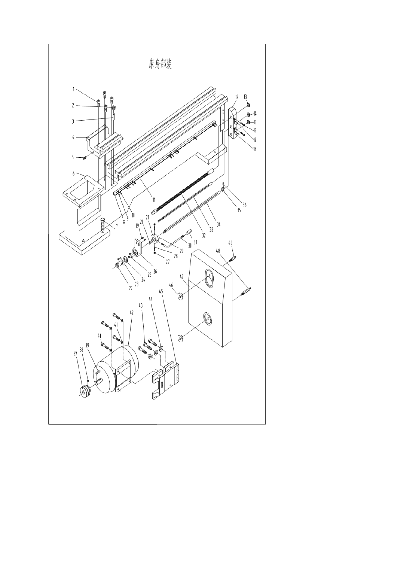
7.3 Bed Assembly
Inde
x
No.
Part
No.
Description
Size
Qt
y

1
GB/T70
Hex Socket Cap Screw
M10×40
4
2
GB/T41
Hex Nut
M8
2
3
GB/T881
Pin
8×75
2
4
CZ1340G-01-015
Gap
1
5
GB/T77
Set Screw
M10×16
1
6
CZ1340G-07-028
Bed
1
7
GB/T5780
Hex Cap Bolt
M12×50
6
8
CZ1340G-01-016
Rack
1
9
GB/T117
Pin
5×25
6
10
GB/T70
Hex Socket Cap Screw
M6×20
8
11
CZ1340G-01-017
Rack
2
12
CZ1340G-07-058
Bracket
1
13
CZ1340G-01-024
Plug
1
14
CZ1340G-01-024
Plug
1
15
CZ1340G-01-024
Plug
1
16
GB/T70
Hex Socket Cap Screw
M8×55
2
17
GB/T117
Pin
6×70
2
18
GB/T1155
Oil Ball
8
2
19
GB/T70
Hex Socket Cap Screw
M6×16
2
20
GB/T119
Pin
8×25
1
21
CZ1340G-01-025
Handle
1
22
CZ1340G-01-030
Collar
1
23
CZ1340G-01-028
Key
1
24
CZ1340G-01-029
Brake Ring
1
25
GB/T2089
Spring
1×6×25
3
26
CZ1340G-07-057
Bracket
1
27
GB/T6172
Hex Nut
M8
2

28
GB/T79
Screw
M8×28
2
29
GB/T879
Pin
3×16
1
30
CZ1340G-01-026
Handle
1
31
JB/T7271.5
Knob
AM10×50
1
32
CZ1340G-01-018
Lead screw
1
33
CZ1340G-01-019
Feed Rod
1
34
CZ1340G-01-020
Shaft
1
35
CZ1340G-01-021
Collar
1
36
GB/T78
Set Screw
M6×10
1
37
CZ1340G-01-006
Pulley
1
38
GB/T77
Screw
1
39
GB/T1096
Key
8×40
1
40
GB/T5780
Hex Cap Bolt
M8×25
4
41
GB/T97
Washer
10
4
42
Motor
2HP(1.5KW)
1
43
GB/T5780
Hex Cap Bolt
M10×35
3
44
GB/T96
Washer
10
3
45
CZ1340G-01-005
Motor Mounting Plate
1
46
CZ1340G-02-001
Lock Nut
2
47
CZ1340G-00-005
Cover
1
48
CZ1340G-02-002
Screw
1
49
CZ1340G-02-002
Screw
1

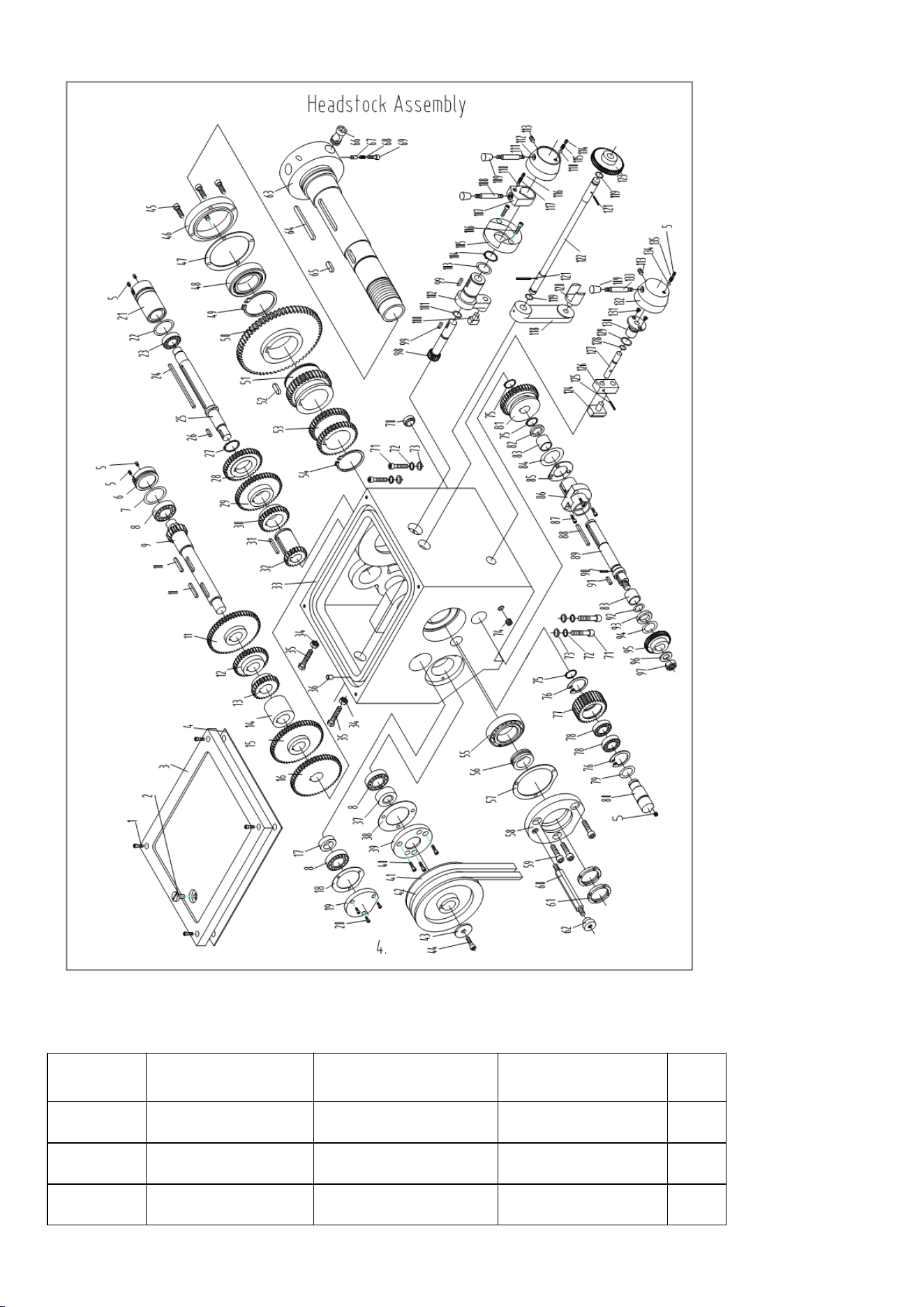
7.4 Headstock Assembly
Index No.
Part No.
Description
Size
Qty.
1
GB/T70
Screw
M6×16
6
2
CZ1340G-02-009
Screw
1
3
CZ1340G-02-007
Cover
1
4
CZ1340G-02-008
Gasket
1
5
GB/T77
Screw
M6×8
6
6
CZ1340G-02-031
Plug
1
7
GB/T7757.2
O-Ring
41.3×3.1
1
8
GB/T276
Bearing
6204/P6
3
9
CZ1340G-02-030
Gear Shaft
1
10
GB/T1096
Key
6×56
2
11
CZ1340G-02-032
Gear
53T
1
12
CZ1340G-02-029
Gear
34T
1
13
CZ1340G-02-028
Gear
26T
1
14
CZ1340G-02-027
Collar
1
15
CZ1340G-02-067
Gear
43T
1
16
CZ1340G-02-065
Gear
51T
1
17
CZ1340G-02-066
Washer
1
18
CZ1340G-02-064
Gasket
1
19
CZ1340G-02-063
Rear Cover
1
20
GB/T70
Screw
M4×12
3
21
CZ1340G-02-026
Plug
1
22
GB/T7757.2
Bearing
34.7×3.1
1
23
GB/T276
Bearing
6203/P6
1
24
GB/T1096
Key
6×120
1
25
CZ1340G-02-025
Shaft
1
26
GB/T1096
Key
5×20
1

27
GB/T894.1
C-Clip
35
1
28
CZ1340G-02-022
Gear
38T
1
29
CZ1340G-02-021
Gear
46T
1
30
CZ1340G-02-019
Gear
29T
1
31
GB/T1096
Key
5×50
1
32
CZ1340G-02-018
Gear
21T
1
33
CZ1340G-02-006
Main Casting
1
34
GB/T41
Hex Nut
M8
2
35
GB/T5781
Screw
M8×50
2
36
CZ1340G-02-010
Oil Pipe
2
37
GB/T9877.1
Oil Seal
B20408B
1
38
CZ1340G-02-017
Gasket
1
39
CZ1340G-02-016
Cover
1
40
GB/T70
Screw
M6×16
3
41
GB/T1171.1
V-Belt
A787
2
42
CZ1340G-02-015
Pulley
1
43
CZ1340G-02-013
Washer
1
44
GB/T70
Screw
M8×20
1
45
GB/T70
Screw
M6×25
4
46
CZ1340G-02-011
Front Cover
1
47
CZ1340G-02-012
Gasket
1
48
GB/T279
Bearing
30212/P5
1
49
Gb/T894.1
C-Clip
72
1
50
CZ1340G-02-036
Gear
74T
1
51
CZ1340G-02-033
Gear
37T
1
52
GB/T1096
Key
8×18
1
53
CZ1340G-02-037
Gear
37T
1
54
GB/T894.1
C-Clip
50
1

55
GB/T297
Bearing
30210/P5
1
56
CZ1340G-02-062
Collar
1
57
CZ1340G-02-005
Gasket
1
58
CZ1340G-02-004
Rear Cover
1
59
GB/T70
Screw
M6×25
3
60
CZ1340G-02-002
Screw
1
61
GB/T810
Lock Nut
M50
2
62
CZ1340G-02-001
Lock Nut
1
63
CZ1340G-02-003
Spindle
1
64
GB/T1096
Key
8×90
1
65
GB/T1096
Key
6×40
1
66
CZ1340G-02-034
Cam
3
67
CZ1340G-02-035
Pin
3
68
GB/T2089
Spring
0.6×3×10
3
69
GB/T70
Screw
M8×20
3
70
JB/T7941.1
Oil Sight
A20
1
71
GB/T70
Screw
M10×40
4
72
GB/T97.1
Washer
10
4
73
GB/T93
Washer
10
4
74
GB/T77
Screw
M12×12
1
75
GB/T894.1
C-Clip
20
3
76
GB/T893.1
C-Clip
42
2
77
CZ1340G-02-059
Gear
30T
78
GB/T276
Bearing
16004/P6
2
79
GB/T7757.2
O-Ring
19.8×2.65
1
80
CZ1340G-02-061
Shaft
1
81
CZ1340G-02-045
Gear
37T
1
82
CZ1340G-02-051
Washer
1

83
CZ1340G-02-055
Collar
2
84
GB/T7757.2
O-Ring
26.3×3.1
1
85
CZ1340G-02-053
Gasket
1
86
CZ1340G-02-052
Collar
1
87
GB/T70
Screw
M5×16
3
88
GB/T1096
Key
6×50
1
89
CZ1340G-02-054
Shaft
1
90
GB/T879
Pin
3×10
1
91
GB/T1096
Key
×18
1
92
GB/T7757.2
O-Ring
13.8×3.1
1
93
CZ1340G-02-056
Washer
1
94
GB/T10708.3
Oil Seal
24×32×5
1
95
CZ1340G-02-057
Gear
40T
1
96
GB/T97.1
Washer
12
1
97
GB/T41
Nut
M12
1
98
CZ1340G-02-041
Gear Shaft
1
99
GB/T1096
Key
5×16
2
100
CZ1340G-02-038
Shift Fort
1
101
GB/T7757.2
O-Ring
13.8×1.8
1
102
CZ1340G-02-039
Shaft Collar
1
103
GB/T7757.2
O-Ring
25.7×2.65
1
104
GB/T894.1
C-Clip
30
1
105
CZ1340G-02-042
Hub
1
106
GB/T70
Screw
M6×20
2
107
CZ1340G-02-044
Handle Block
1
108
CZ1340G-02-060
Handle
1
109
JB/T7271.5
Lever Sleeve
BM8×40
3
110
GB/T308
Steel Ball
6
2

111
CZ1340G-02-058
Handle
1
112
CZ1340G-02-043
Handle Body
1
113
GB/T71
Screw
M6×12
1
114
GB/T77
Screw
M8×10
1
115
GB/T2089
Spring
0.9×4×20
1
116
GB/T77
Screw
M8×8
1
117
GB/T2089
Spring
0.9×4×7
1
118
CZ1340G-02-024
Shift Lever
1
119
GB/T7757.2
O-Ring
11.8×1.8
2
120
CZ1340G-02-020
Shift Fort
1
121
GB/T879
Pin
5×32
2
122
CZ1340G-02-023
Shaft
1
123
CZ1340G-02-040
Gear
51T
1
124
CZ1340G-02-049
Shift Fork
1
125
GB/T879
Pin
4×18
1
126
CZ1340G-02-050
Shaft Housing
1
127
CZ1340G-02-048
Shaft
1
128
GB/T7757.2
O-Ring
7×1.8
1
129
GB/T7757.2
O-Ring
16×2.65
1
130
CZ1340G-02-047
Shift Hub
1
131
GB/T819
Screw
M4×8
2
132
CZ1340G-02-046
Handle Body
1
133
CZ1340G-02-068
Handle
1
134
GB/T308
Steel Ball
5
1
135
GB/T2089
Spring
0.6×3×18
1
7.5 Gearbox Assembly
Index No.
Part No.
Description
Size
Qty.
3
GB/T70
Screw
M6×16
1
4
CZ1340G-03-007
Shaft Cover
1
5
CZ1340G-07-008
Gear(30T,54T,56T,57
60T,63T,66T,69T,78
9

T,
T)
6
CZ1340G-07-013
Shaft
1
7
GB/T1096
Key
5×18
1
8
GB/T1096
Key
5×45
1
9
GB/T894
C-Clip
20
5
10
GB/T276
Bearing
6004
2
11
CZ1340G-07-018
Gasket
1
12
CZ1340G-07-021
Cover
1
13
GB/T70
Screw
M5×12
18
14
CZ1340G-07-022
Shaft
1
15
GB/T117
Pin
3×32
2
16
GB/T70
Screw
M6×20
3
17
CZ1340G-07-009
Cover
1
18
GB/T1155
Oil Ball
6
1
19
CZ1340G-07-010
Gasket
1
20
GB/T276
Bearing
6203
1
21
CZ1340G-07-012
Cover
1
22
GB/T894
C-Clip
16
2
23
CZ1340G-07-011
Gear
24T,16T
1
24
GB/T276
Bearing
6202
9
25
CZ1340G-07-001
Casting
1
26
GB/T879
Pin
5×20
2
27
GB/T70
Screw
M8×65
2
28
CZ1340G-07-049
Collar
3
29
CM1224C-03-034
Oil Cover
1
30
GB/T894
C-Clip
26
2
31
CZ1340G-07-053
Gear
24T
2
32
CZ1340G-07-052
Gear
28T
2

33
CZ1340G-07-051
Gear
2
34
GB/T1096
Key
4×22
2
35
CZ1340G-07-005
Cover
3
36
CZ1340G-07-004
Gasket
3
37
CZ1340G-07-015
Shaft
1
38
GB/T1096
Key
4×55
1
39
CZ1340G-07-006
Gear
24T
1
40
CZ1340G-07-007
Gear
16T
1
41
CZ1340G-07-014
Gear
32T
1
42
GB/T77
Screw
M5×16
2
43
CZ1340G-07-059
Cover
1
44
CZ1340G-07-047
Gear
32T
1
45
CZ1340G-07-045
Gasket
1
46
CZ1340G-07-044
Cover
1
47
CZ1340G-07-002
Gear
16T
1
48
CZ1340G-07-003
Shaft
1
49
GB/T70
Screw
M10×16
1
50
GB/T3452.1
O-Ring
9.5×1.8
5
51
D97-4-20
Locking Connector of
Tube
1
Index No.
Part No.
Description
Size
Qty.
52
GB/T70
Screw
M8×25
2
53
GB/T117
Pin
6×25
2
54
GB/T9877.1
Oil Seal
28×40×7
1
55
GB/T1096
Key
5×20
1
56
CZ1340G-07-043
Shaft
1
57
CZ1340G-07-056
Gear
32T
1
58
CZ1340G-07-055
Cover
1

59
CZ1340G-07-054
Gear
30T
1
60
CZ1340G-07-016
Gear
28T
1
61
CZ1340G-07-027
Shaft
2
62
GB/T41
Nut
M5
4
63
GB/T75
Screw
M5×16
4
64
CZ1340G-07-024
Slip Fitting
1
65
CZ1340G-07-026
Rack
1
66
CZ1340G-07-023
Slip Fitting
1
67
CZ1340G-07-029
Slip Fitting
2
68
CZ1340G-07-025
Rack
1
69
CZ1340G-07-030
Rack
1
70
CZ1340G-07-037
Gear Shaft
4
71
CZ1340G-07-034
Rack
1
72
CZ1340G-07-033
Gasket
1
73
GB/T77
Screw
M6×10
4
74
CZ1340G-07-038
Engaging Arm
1
75
GB/T65
Screw
M4×55
2
76
LXW5-11G2
Switch
2
77
CZ1340G-07-048
Lid
1
78
CZ1340G-07-017
Gear
30T
1
79
CZ1340G-07-019
Cover
1
80
CZ1340G-07-050
Shaft
1
81
GB/T1096
Key
4×145
1
82
CZ1340G-07-020
Gear
16T
1
83
CZ1340G-07-046
Shaft
1
84
GB/T117
Pin
3×25
1
85
CZ1340G-07-039
Cover
1
86
GB/T70
Screw
M5×25
8

87
GB/T3452.1
O-Ring
6.9*1.8
4
88
CZ1340G-07-035
Washer
4
89
GB/T879
Pin
4×40
4
90
GB/T879
Pin
4×25
2
91
GB/T1160.1
Oil Sight Glass
20
1
92
CZ1340G-07-036
Handle Body
4
93
GB/T308
Steel Ball
6.5
4
94
GB/T2089
Spring
1×5×20
4
95
GB/T77
Screw
M8×10
4
96
CZ1340G-07-041
Panel
4
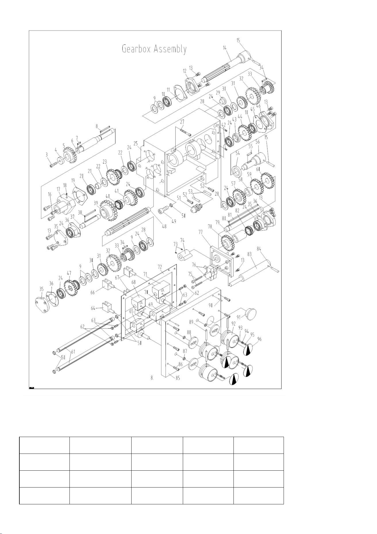
7.6 Saddle and Cross Slide Assembly
NO
Part NO
Description
Size
QTY
1
JB/T4141.5
Handle
M8H63
1
2
CZ1340G-05-023
Screw
1
3
CZ1340G-05-022
Washer
1

4
CZ1340G-05-021
Handle Wheel
1
5
CZ1340G-05-038
Dial Ring
1
6
GB/T77
Screw
M6H8
1
7
GB/T70
Screw
M6H25
2
8
GB/T301
Bearing
51104
1
9
CZ1340G-05-020
Hub
1
10
JB/T7940.4
Oil Ball
6
1
11
GB/T5781
Screw
M8H20
4
12
CZ1340G-05-013
Strip
2
13
CZ1340G-05-039
Saddle
1
14
GB/T823
Screw
M4H12
8
15
CZ1340G-05-013
Plate
2
16
CZ1340G-05-014
Plate
2
17
GB/T70
Screw
M8H30
4
18
GB/T118
Taper Pin
A8H40
2
19
CZ1340G-05-006
Plate
2
20
CZ1340G-05-007
Plate
2
21
GB/T6170
Nut
M6
4
22
GB/T71
Screw
M6H16
4
23
GB/T5781
Screw
M8H25
3
24
JB/T7940.4
Oil Ball
8
2
25
CZ1340G-05-019
Sleeve
1
26
GB/T1096
Key
4H4H20
1
27
CZ1340G-05-018
Gear Shaft
1
28
GB/T68
Screw
M3H6
1
29
GB/T1096
Key
5H5H30
1
30
CZ1340G-05-008
Lead Screw
1
31
CZ1340G-05-010
Lead Nut
1

32
GB/T70
Screw
M6H16
1
33
GB/T301
Bearing
51101
2
34
CZ1340G-05-003
Bearing
Housing
1
35
GB/T93
Spring
Washer
8
2
36
GB/T70
Screw
M8H25
2
37
CZ1340G-05-002
Anti-dust
Cover
1
38
CZ1340G-05-001
Sleeve
1
39
GB/T858
Washer
12
1
40
GB/T810
Nut
M12
1
41
CZ1340G-05-032
Set Screw
2
42
CZ1340G-05-031
Gib
1
43
CZ1340G-05-039
Cross Slide
1
44
CZ1340G-05-017
T-Bolt
2
45
GB/T70
Screw
M8H16
1
46
CZ1340G-05-011
Sleeve
1
47
JB/T7940.4
Oil Ball
8
3
48
GB/T78
Screw
M8H10
1
49
CZ1340G-05-004
Bead
1
50
CZ1340G-05-005
Gib
2
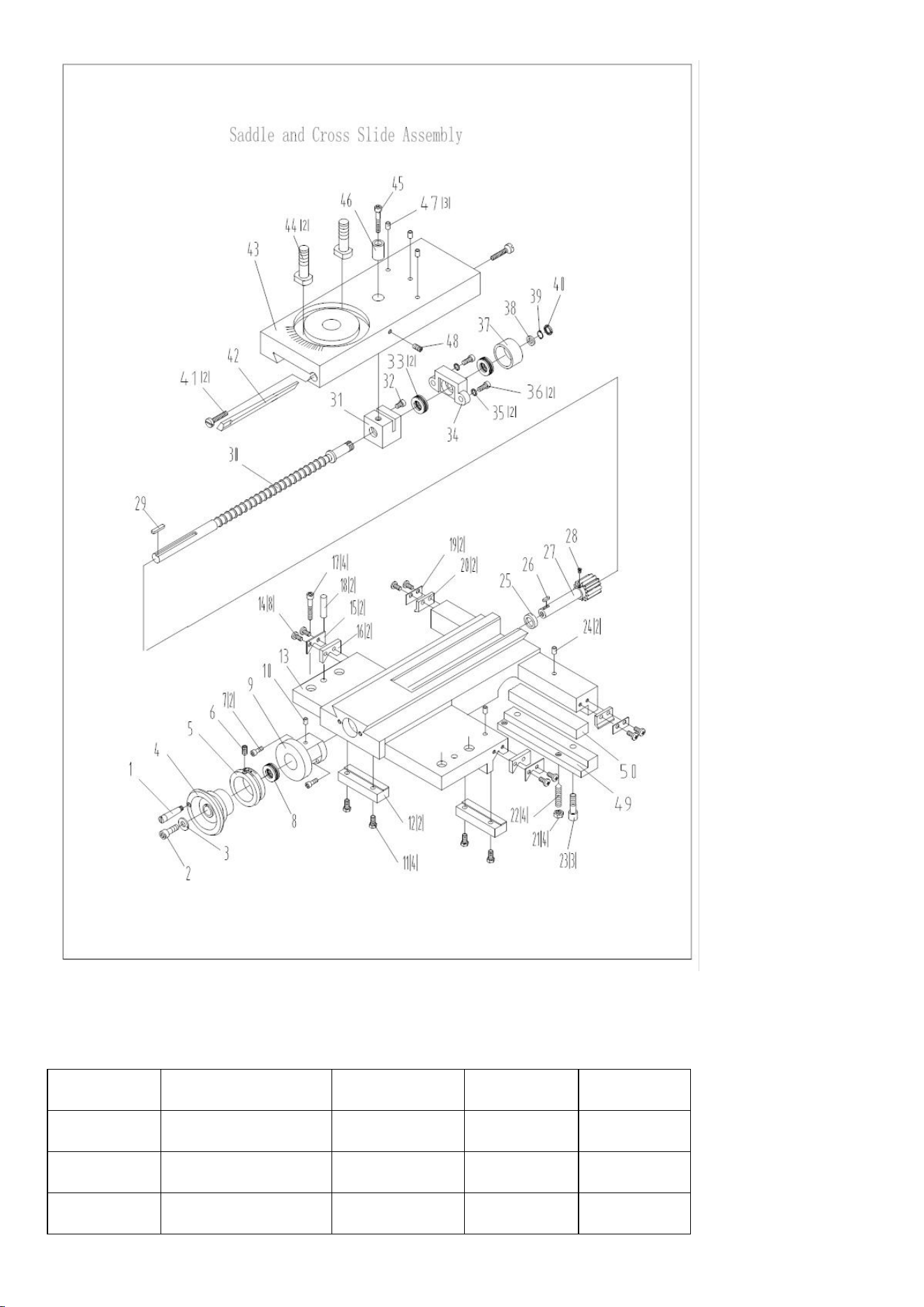
7.7 Tool Post Assembly
Index NO
Part NO
Description
Size
QTY
1
JB/T7271.5
Knob
M10H50
1
2
JB/T7271.6
Handle Rod
1
3
CZ1340G-05-026
Lock Nut
1

4
CZ1340G-05-024
Washer
1
5
GB/T83
Screw
M10H40
8
6
CZ1340G-05-029
Post Base
1
7
CZ1340G-05-025
Screw
1
8
GB/T78
Screw
M6H10
2
9
CZ1340G-05-030
Stop
1
10
GB/T2089
Spring
0.4H4H18
1
11
CZ1340G-05-028
Top Slide
1
12
JB/T7940.4
Oil Ball
6
3
13
GB/T78-85
Screw
M6H10
1
14
GB/T301
Bearing
51101
2
5
CZ1340G-05-034
Collar
1
16
GB/T70
Screw
M6H20
2
17
GB/T6173
Nut
M12H1
2
18
GB/T78
Screw
M6H6
1
19
CZ1340G-05-036
Dial Ring
1
20
GB/T117
Pin
A3H16
1
21
GB/T72701.9
Handle
8H25
1
22
CZ1340G-05-035
Lead Screw
1
23
CZ1340G-05-033
Lead Nut
1
24
GB/T6170
Nut
M8
2
25
GB/T97.2
Washer
2
26
CZ1340G-05-016
Set Screw
2
27
CZ1340G-05-015
Gib
1
28
CZ1340G-05-027
Swivel Slide
1
29
GB/T73
Screw
M8H8
1
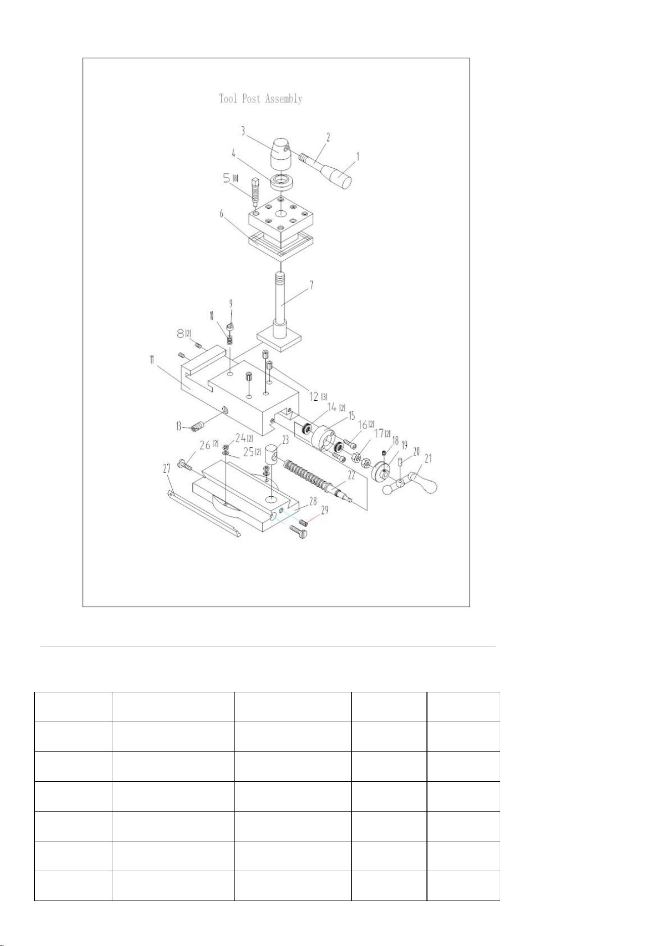
7.8 Apron Assemly
Index NO.
Part NO.
Description
Size
QTY
1
GB/T5780
M6H10
1
2
CZ1340G-04-030
Screw
1
3
CZ1340G-04-016
Washer
22T
1
4
GB/T1096
Gear
5H12
1
5
CZ1340G-04-015
Key
1
6
GB/T3452.1
Shaft
20H2.4
1

7
CZ1340G-04-013
O-Ring
40T
1
8
GB/T879
Gear
5H30
1
9
CZ1340G-04-004
Pin
13T
1
10
GB/T879
Gear Shaft
5H30
1
11
CZ1340G-04-005
Pin
60T
1
12
CZ1340G-04-047
Gear
1
13
GB/T70
Bracket
M6H16
1
14
CZ1340G-04-001
Screw
1
15
GB/T3452.1
Apron box
12H2.4
1
16
GB/T5781
O-Ring
M12H25
1
17
CZ1340G-04-029
Screw
1
18
CZ1340G-04-002
Cover
14T
1
19
GB/T1096
Gear shaft
A5H18
1
20
JB/T7940.4
Key
8
1
21
CZ1340G-04-003
Oil Ball
1
22
GB/T70
Dial Seat
M6H25
3
23
GB/T78
Screw
M5H6
1
24
CZ1340G-04-048
Screw
1
25
CZ1340G-04-045
Dial
1
26
CZ1340G-04-046
Hand wheel
1
27
GB/T70
Washer
M6H16
1
28
CZ1340G-04-043
Screw
1
29
CZ1340G-04-044
Screw
1
30
GB/T4141.14
Handle
M8H16
1
31
CZ1340G-04-009
Handle
1
32
CZ1340G-04-008
Handle Rod
1
33
GB/T70
Shift lever
M6H25
3
34
CZ1340G-04-007
Screw
1

35
GB/T308
Box
5
2
36
GB/T1239.2-89
Steal Ball
0.8H4H20
2
37
GB/T77
Spring
M6H6
2
38
CZ1340G-04-022
Screw
1
39
GB/T70
Cover
M6H12
4
40
GB/T879
Spring
5H20
1
41
CZ1340G-04-006
Cover
1
42
CZ1340G-04-028
Gear
63T
1
43
GB/T119
Pin
B8H25
3
44
CZ1340G-04-024
Bushing
1
45
GB/T119
Pin
A3H25
1
46
CZ1340G-04-027
Gear
40T
1
47
GB/T77
Screw
M5H12
2
48
CZ1340G-04-023
Gear
30T
1
49
JB/T7941.1
Oil Sight
12
1
50
CZ1340G-04-041
Oil Plug
1
51
CZ1340G-04-033
Bushing
1
52
CZ1340G-04-026
Shaft
1
53
GB/T70
Screw
M5H12
2
54
CZ1340G-04-012
Shaft
1
55
CZ1340G-04-011
Gear
18T
1
56
CZ1340G-04-010
Washer
1
57
GB/T70
Screw
M6H10
1
58
GB/T83
Screw
M5H5
1
59
GB/T77
Screw
M6H10
1
60
CZ1340G-04-034
Bar
1
61
CZ1340G-04-018
Half Nut
1
62
GB/T5781
Bolt
M6H12
2

63
GB/T79
Screw
M6H35
2
64
GB/T6170
Nut
M6
2
65
GB/T5781
Screw
M5H16
3
66
CZ1340G-04-019
Nut seat
1
67
GB/T6170
Nut
M5
3
68
GB/T77
Screw
M5H16
3
69
CZ1340G-04-021
Gib
1
70
GB/T119
Pin
6H12
2
71
CZ1340G-04-017
Shaft
1
72
CZ1340G-04-020
Handle Seat
1
73
CZ1340G-04-042
Handle Rod
1
74
GB/T4141.14
Knob
M8H40
1
75
GB/T6170
Nut
M8
1
76
GB/T93
Washer
8
1
77
CZ1340G-04-035
Bushing
1
78
CZ1340G-04-036
Gear
1
79
CZ1340G-04-037
Bushing
1
80
CZ1340G-04-040
Bushing
1
81
CZ1340G-04-039
Theading dial
body
1
82
GB/T70-85
Screw
M8×50
1
83
CZ1340G-04-038
Theading dial
shaft
1
84
GB/T827-86
Rivet
3×8
1
85
JB/T7940.4
Oil cup
6
1
86
CZ1340G-04-014
Worm
1
87
CZ1340G-04-031
Key
1
88
CZ1340G-04-032
Pin
1
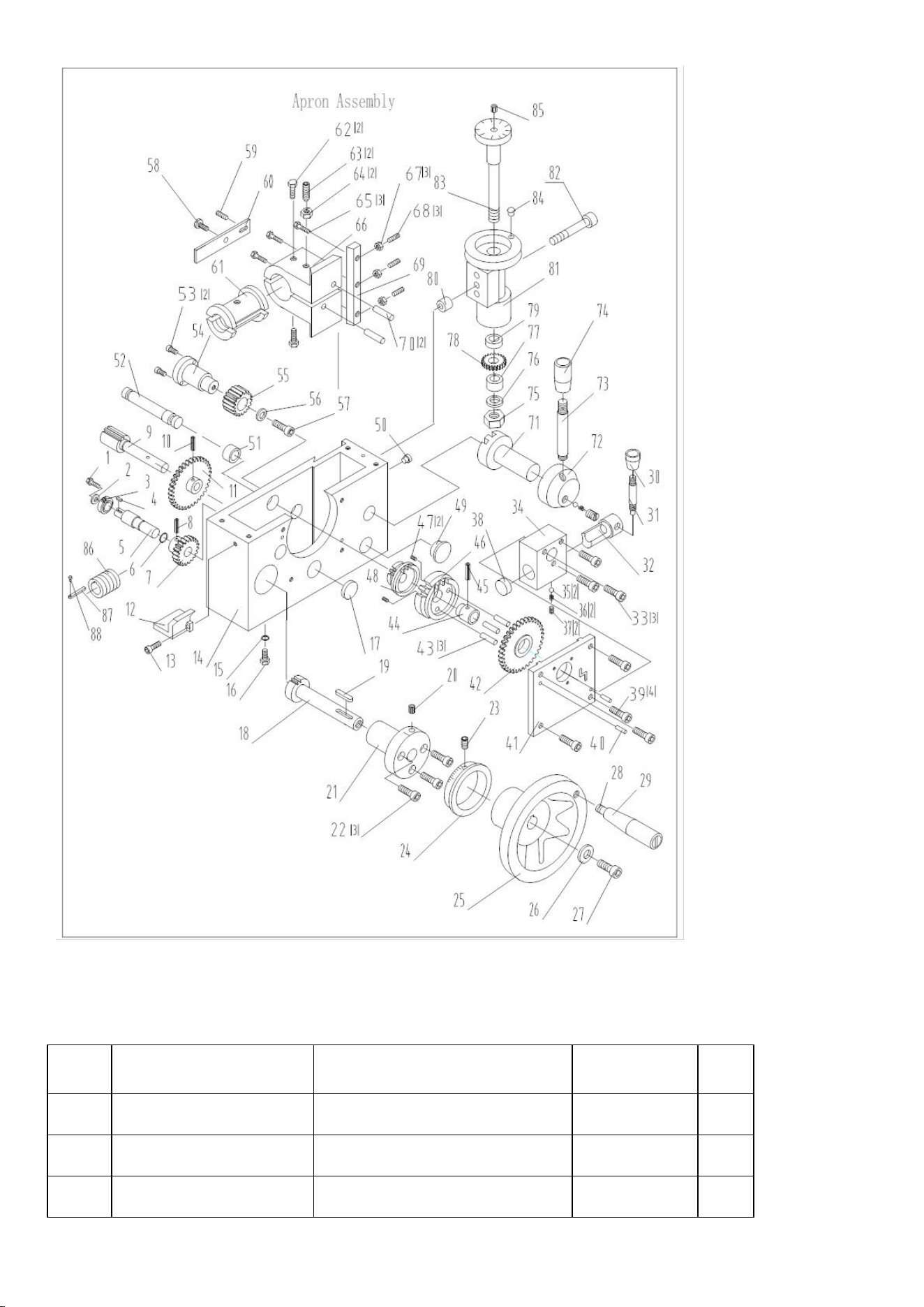
7.9 Tailstock Assembly
No.
Part No.
Description
Size
Qty.
1
CZ1340G-06-020
Base
1
2
CZ1340G-06-017
Screw
1
3
CZ1340G-06-018
Collar
1

4
GB/T879
Pin
5×26
1
5
GB/T41
Nut
M8
1
6
GB/T79
Screw
M8×35
1
7
CZ1340G-06-019
Shaft
1
8
JB/T7271.5
Knob
BM10×50
1
9
CZ1340G-06-012
Lever
1
10
JB/T7271.5
Knob
BM8×40
1
11
CZ1340G-06-013
Screw
1
12
CZ1340G-06-015
Shaft
1
13
CZ1340G-06-014
Screw
2
14
JB/T7940.4
Oiler
8
2
15
CZ1340G-06-004
Nut
1
16
GB/T70-85
Screw
M4×12
3
17
CZ1340G-06-006
Index ring
1
18
CZ1340G-06-003
Screw
1
19
GB/T1096
Key
4×16
1
20
CZ1340G-06-010
Handle
4
21
GB/T301
Bearing
51102
1
22
CZ1340G-06-005
Flange cover
1
23
JB/T7940.4
Oiler
8
1
24
GB/T78
Screw
M5×20
1
25
CZ1340G-06-011
Screw
1
26
GB/T70
Screw
M6×16
4
27
CZ1340G-06-009
Screw
1
28
CZ1340G-06-008
Washer
1
29
CZ1340G-06-007
Hand wheel
1
30
GB/T75
Screw
M610
1
31
CZ1340G-06-016
Pivot block
1
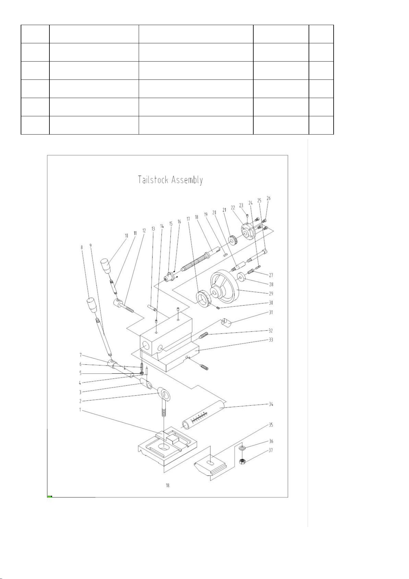
32
GB/T78
Screw
M1045
3
33
CZ1340G-06-001
Casting
1
34
CZ1340G-06-002
Quill
M.T3
1
35
CZ1340G-06-021
Clamp plate
1
36
GB/T95
Washer
12
1
37
GB/T41
Nut
M12
1
7.10 Brake Part

Index No.
Part No.
Description
Size
Qty.
1
CZ1340G-01T02-017
Limiting pin
2
2
CZ1340G-01T02-009
Extension spring
2
3
GB/T70-85
Screw
M8×20
8
4
CZ1340G-01T02-012
Left oscillator arm
1
5
CZ1340G-01T02-018
Shaft
2
6
CZ1340G-01T02-013
Pin
1
7
GB/T41-86
Nut
M10
2
8
CZ1340G-01T02-008
Adjusting bolt
1
9
GB/T91
Placket pin
1
10
GB/T41-86
Nut
M8
1
11
GB/T5783-86
Screw
M8×40
1
12
Limiting switch
JLXK1-311
1
13
GB/T822-85
Screw
M3×8
4
14
GB/T41-86
Nut
M12
10
15
CZ1340G-01T02-007
Mount seat
1
16
GB/T70-85
Screw
M6×14
3
17
GB/T95-85
Washer
6
2
18
CZ1340G-01T02-006
Pressure plate
1
19
GB/T70-85
Screw
M5×10
2
20
CZ1340G-01T02-011
Shaft
2
21
CM1224C-00-015
Cable gripe
1
22
Brake wire
Ø5×1120
1
23
GB/T95-85
Washer
8
2
24
CZ1340G-01T02-005A
Limiting block
1
25
CZ1340G-01T02-004
Spring
1
26
CZ1340G-01T02-002
Pin
1
27
CZ1340G-01T02-001
Adjusting nut
1

28
GB/T70-85
Screw
M6×25
1
29
CZ1340G-02-013
Washer
1
30
CZ1237G-02-060A
Pulley
1
31
Gripe piece
1
32
CZ1340G-01T02-023
Pin
1
33
CZ1340G-01T02-003
Arm
1
34
GB/T879-86
Spring pin
4×16
1
35
CZ1340G-01T02-022
Cover
1
36
CZ1340G-01T02-025
Bolt
1
37
GB/T70-85
Screw
M6×12
3
38
CZ1340G-01T02-019
Right oscillator arm
1
39
CZ1340G-01T02-016
Brake pedal
1
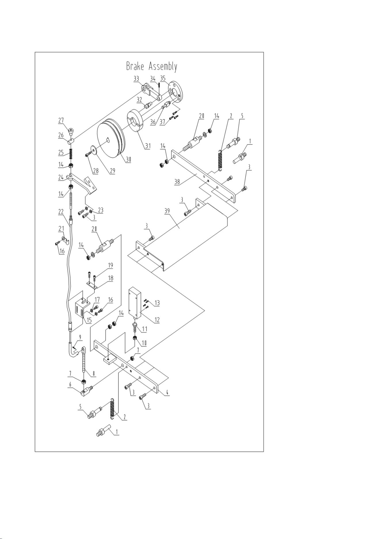
7.11 Follow Rest

Inde
x
No.
Part
No.
Description
Size
Qt
y
1
JB/T7274.4
Knob
8×40
2
2
GB/T879
Pin
3×18
2
3
CZ1340G-05T03-010
Bushing
2
4
CZ1340G-05T2-003
Screw
2
5
CZ1340G-05T03-008
Brass Finger
2
6
CZ1340G-05T02-002
Sleeve
2
7
GB/T77
Set Screw
M6×8
2
8
GB/T79
Set Screw
M6×16
2
9
GB/T6170
Nut
M6
2
10
GB/T70
Hex Socket Cap Screw
M8×45
1
11
CZ1340G-05T02-001
Base Casting
1
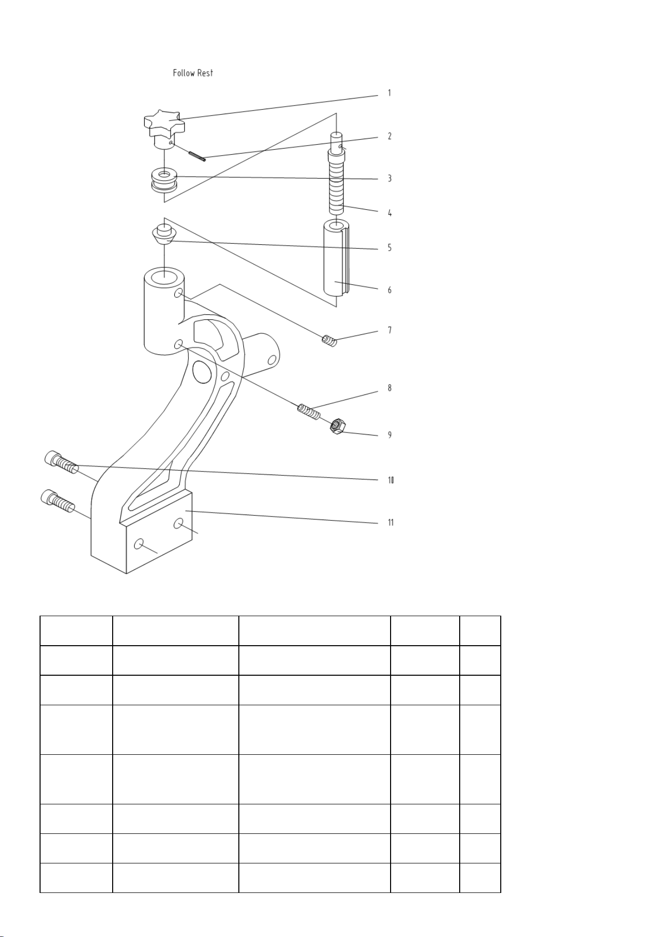
7.12 Steady Rest
Index No.
Part No.
Description
Size
Qty
1
JB/T7274.4
Knob
8×40
3
2
GB/T879
Pin
3×18
3
3
CZ1340G-05T03-00
9
Screw
3
4
CZ1340G-05T03-01
1
Sleeve
3
5
GB/T78
Set Screw
M6×8
3
6
GB/T6170
Nut
M6
4
7
CZ1340G-05T03-00
Bolt
M6×30
1

7
8
GB/T79
Set Screw
M6×16
3
9
CZ1340G-05T03-00
3
Base Casting
1
10
CZ1340G-05T03-00
2
Clamp Screw
1
11
CZ1340G-05T03-00
1
Clamp Pad
1
12
GB/T96
Flat Washer
12
1
13
GB/T6170
Nut
M12
1
14
GB/T119
Pin
A5×25
1
15
CZ1340G-05T03-00
4
Pivot Bolt
1
16
CZ1340G-05T03-00
5
Lock Knob
1
17
CZ1340G-05T03-00
6
Top Casting
1
18
CZ1340G-05T03-00
8
Brass Finger
3
19
CZ1340G-05T03-01
0
Bushing
3
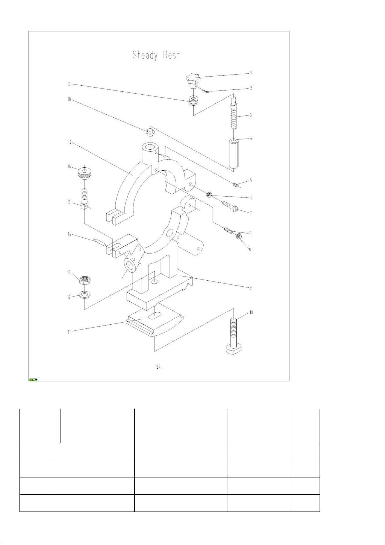
7.13 Electric Box Assembly
Index
No
Part No
Description
Size
Qty
1
CZ1340G-09-001
Door of electrical box
1
2
CZ1340G-09-007
Pad
1
3
CZ1340G-09-005
Panel
1
4
CZ1340G-09-011(1)
Wiring diagram
1

5
XB7-EA.1
Green button
1
6
XB2-ES542
Emergency switch
1
7
XB7-EV6
Indicator
1
8
GB/T818
Screw
M4×8
10
9
LC1-D259
Contactor
2
10
GB/T818
Screw
M4×12
6
11
CZ1340G-09-006
Label
7
12
GB/T41
Nut
M6
4
13
GB/T818
Screw
M4×16
2
14
JH9-1.5ZG
Terminal plate
1
15
CZ1340G-09-009
Earth terminal
1
16
JBK3-63
Transformer
1
17
CZ1340G-09-003
Wiring plate
1
18
JH9-6ZG
Terminal plate
1
19
CA2-DN140
Relay
1
20
D97-4-20
Tube connector
1
21
D97-4-24
Tube connector
2
22
GB/T818
Screw
M6×10
4
23
CZ1340G-09-002
Electric box
1
24
CZ1340G-09-004
Warning sign
1