
1. INTRODUCTION
Thank you for purchasing the MechMaxx 1337GN Bench Lathe. This manual is designed to guide you through the
setup, operation, maintenance, and safety procedures for your lathe. Please read this manual thoroughly before using
the machine to ensure proper operation and optimal performance.
The MechMaxx 1337GN is a high-precision engine lathe built for both professional and advanced hobbyist use. It
features a robust construction, precision-ground bedways, and a powerful 3 HP motor. The machine is equipped with a
Norton-style quick-change gearbox for easy feed and thread selection, a dedicated leadscrew for threading operations,
and a separate feed rod for power feed.
With a spindle bore of 40 mm and a full range of inch and metric threading capabilities, the 1337GN is suitable for a
wide range of turning applications, from small parts to larger workpieces. Its reliable performance, smooth controls,
and safety features make it an excellent addition to any workshop.
We recommend familiarizing yourself with all operating procedures and safety precautions outlined in this manual
before attempting any machining tasks. Proper usage and regular maintenance will ensure many years of trouble-free
service from your MechMaxx lathe.

2. SPECIFICATIONS
Specification
Value
Swing over bed
13" (330 mm)
Swing over cross slide
8-1/2" (215 mm)
Swing over gap
19" (485 mm)
Distance between centers
37" (940 mm)
Bed width
7-1/8" (182 mm)
Spindle bore
1.57" (40 mm)
Spindle taper
MT#5
Tailstock taper
MT#3
Tailstock quill travel
3-3/4" (95 mm)
Cross slide travel
5-7/8" (150 mm)
Compound slide travel
3-3/8" (85 mm)
Carriage (saddle) travel
31-7/8" (810 mm)
Spindle speed range
9 speeds: 64 – 1500 RPM
Leadscrew diameter & pitch
Ø22 mm, 8 TPI
Feed rod diameter
Ø19 mm
Threading range – Inch
14 kinds: 7 – 48 TPI
Threading range – Metric
11 kinds: 0.5 – 3.0 mm pitch
Power feed – Longitudinal
0.002 – 0.012 in./rev.
Power feed – Cross
0.004 – 0.010 in./rev.
Spindle speed change method
Gear change via 2 lever + 1 feed selector
Motor
1.5 HP (1.1 kW), 220V, single-phase
Net weight (w/o stand)
727 lbs (330 kg)
Net weight (with stand)
860 lbs (390 kg)
Shipping dimensions (lathe only)
70" × 29" × 30" (1780 × 740 × 750 mm)

3. SAFETY INSTRUCTIONS
Before operating the 1337GN lathe, please read and follow all safety precautions below to prevent injury and ensure
safe machine operation.
WARNING! Serious Injury or Death Can Occur if Safety Instructions Are Ignored.
Disconnect power before servicing, cleaning, or changing any accessories.
Do not operate the lathe without all guards in place (e.g., chuck guard, belt cover).
Never wear gloves, neckties, jewelry, or loose clothing when operating the machine.
Keep hands, hair, and tools away from rotating parts.
Use appropriate work-holding devices to secure the workpiece. Never hold workpieces by hand.
Use a brush or tool to remove chips—never your hands.
Always stop the lathe completely before making speed or gear changes.
Do not exceed recommended cutting speeds or feed rates.
Maintain a safe distance while the machine is running.
Personal Protective Equipment (PPE) Required
ANSI-approved safety glasses or face shield
Protective footwear (steel-toe boots recommended)
Hearing protection if operating in noisy environments
Avoid long sleeves or tie them securely
Electrical Safety
Ensure the lathe is properly grounded before connecting to power.
Do not operate in wet or damp conditions.
Never bypass or modify electrical components (e.g., limit switches, emergency stop).
Use a properly rated circuit breaker or fuse according to the motor specifications.

Emergency Stop & Power Down
Familiarize yourself with the Emergency Stop Button before use.
In case of any unusual noise, vibration, or unsafe condition, press the E-Stop immediately and disconnect power.
Do not restart the lathe until the issue has been properly identified and corrected.
Fire Prevention & Ventilation
Do not use flammable coolants or solvents near the machine.
Ensure the workspace is well ventilated to prevent overheating or smoke buildup.
Keep a fire extinguisher rated for electrical and metal fires nearby.
Training & Supervision
This lathe should only be operated by trained personnel or under qualified supervision.
New users must review all safety instructions and perform trial runs before actual cutting.

4. INSTALLATION & SETUP
Proper installation is essential to ensure the accuracy, safety, and long-term reliability of your 1337GN bench lathe.
Please follow the guidelines below before operating the machine.
4.1 Unpacking and Handling
Carefully remove the lathe and all accessories from the shipping crate.
Inspect the machine for damage that may have occurred during shipping. Report any issues immediately.
Do not discard the packaging materials until installation is complete and the lathe is fully tested.
Use a hoist or forklift rated for at least 1000 lbs (450 kg) to lift the machine.
Lifting Note: Use nylon straps or chains through the lifting eye bolts (if equipped), or position under the bed
casting. Do not lift using the chuck, leadscrew, or motor as contact points.
4.2 Site Requirements
Install the lathe on a solid, level concrete floor free of vibration.
Ambient temperature should remain between 41–95°F (5–35°C).
Allow at least 24" (600 mm) of clearance on all sides for access and maintenance.
4.3 Mounting the Lathe
If using a factory stand or cabinet base, align the lathe mounting holes with the stand, and secure using the
supplied hardware.
If mounting directly to a bench, ensure it can support at least 860 lbs (390 kg).
Level the lathe using leveling feet or shims under the stand/base.
4.4 Leveling the Machine
Accurate leveling ensures proper carriage travel and prevents twisting of the bed.
Tools required: 6" machinist’s precision level
1. Place the level directly on the bedways, parallel to the spindle axis (longitudinal direction).
2. Adjust the leveling feet or shim points until the bubble is centered.
3. Repeat the process across the bed (crosswise direction).
4. Recheck after 24–48 hours of use and adjust if necessary.
Do not use a carpenter’s level. Use only a precision level with sensitivity of at least 0.0005"/10".

4.5 Electrical Requirements
Voltage: 220V, 1-phase, 60 Hz
Minimum Circuit: 15A
Power Cord: Use a properly grounded plug and outlet; grounding is required.
Extension cords are not recommended.
Before powering the machine:
Ensure all switches are in the OFF position.
Confirm correct spindle rotation (clockwise facing the chuck).
If the spindle runs in reverse, switch two input wires (for models with reversible polarity).
Do not modify the electrical system. All wiring changes should be done by a qualified electrician.

5. OPERATIONS
This chapter explains the main operating procedures of the MechMaxx 1337GN lathe, which features a Norton-style
quick-change gearbox, a dedicated feed rod and leadscrew, and a dual-lever spindle speed system. Read carefully to
ensure correct and safe usage.
5.1 Control Panel Overview
The 1337GN lathe is equipped with the following control elements:
Control Element
Description
Main Power Switch (Finger Guard Type)
Turns machine ON/OFF; includes safety interlock.
Emergency Stop Button
Instantly cuts all power to the machine.
Power Indicator Light
Lights up when the machine is powered ON.
Inching Button (Jog)
Briefly turns the spindle for precise alignment or setup.
Spindle Direction Lever
Selects spindle rotation: FORWARD / STOP / REVERSE.
Gear Lever A (Speed Range Selector)
Sets the main spindle speed range (A, B, C).
Gear Lever B (Speed Step Selector)
Sets the spindle speed step (1, 2, 3).
Feed/Threading Selector Lever
Switches between feed rod (power feed) and leadscrew (threading).
Feed Direction Lever
Changes direction of automatic feed (FORWARD / REVERSE).
The Norton gearbox handwheels are located on the apron and are not part of the control panel. They are used
to select feed rate and thread pitch.
5.2 Spindle Speed Selection
Spindle speeds are selected using two mechanical gear levers on the headstock: Lever A selects the range (A–C), and
Lever B selects the speed step (1–3), for a total of 9 spindle speeds.
Lever A
Lever B
RPM
A
1
64
A
2
460
A
3
380
B
1
210

Lever A
Lever B
RPM
B
2
1500
B
3
1300
C
1
130
C
2
940
C
3
790
Speed Change Instructions:
1. Stop the spindle completely.
2. Set Lever A to the desired range (A, B, or C).
3. Set Lever B to the desired gear step (1, 2, or 3).
4. If shifting is difficult, rotate the chuck slightly by hand.
Never change gear levers while the spindle is running.
5.3 Feed System and Carriage Travel
The 1337GN lathe uses a dedicated feed rod for power feed and a leadscrew for thread cutting, controlled via a
selector lever.
Carriage Controls:
• Longitudinal Feed (Z-axis): Powered by the feed rod. Engage using the apron’s feed lever.
• Cross Feed (X-axis): Manual control using cross-slide handwheel.
• Compound Slide: Manual feed for taper or angle cuts.
Feed / Thread Selector Lever:
• Switches drive between feed rod and leadscrew.
• Only shift with spindle OFF.
Feed Direction Lever:
• Selects feed direction (Forward / Reverse).
• Always disengage power feed before switching.
Feed Rate Selection:
• Use the two Norton gearbox selector levers to choose feed rate.
• Refer to the feed chart on the machine face.

Do not engage the half-nut lever while feed rod is in use.
5.4 Thread Cutting
The 1337GN supports both inch and metric threading using the leadscrew and Norton gearbox.
Steps for Threading:
1. Check the threading chart for pitch settings.
2. Install change gears if required.
3. Set the feed/thread selector to Threading (leadscrew).
4. Adjust Norton levers to match desired thread pitch.
5. Start the spindle in FORWARD.
6. Engage half-nut at matching indicator point.
7. Disengage half-nut to stop threading travel.
Always stop the spindle before changing pitch or gear settings.
Threading Dial:
• For inch threads, use the threading dial to sync half-nut engagement on each pass.
5.5 Tailstock Operation
Use the tailstock to support long parts or mount drill chucks.
1. Loosen clamping lever and slide tailstock to position.
2. Lock it to the bed.
3. Advance or retract the quill with the handwheel.
4. Lock the quill as needed during cutting or drilling.
5.6 Tool Post Setup
The 1337GN comes with a 4-way turret tool post:
1. Insert the tool bit and set the proper height using shims.
2. Lock the tool holder in place.
3. Rotate the turret to the desired station.
4. Secure with locking handle.

6. MAINTENANCE AND LUBRICATION
Routine maintenance and proper lubrication are essential for the safe operation, accuracy, and extended life
of your 1337GN lathe. This section outlines recommended cleaning, adjustment, inspection, and lubrication
procedures.
6.1 Daily Maintenance Checklist
Perform the following tasks before and after each use:
• Wipe all exposed surfaces clean of chips, dust, and moisture.
• Lightly oil the bedways, lead screw, cross slide, and compound slide.
• Inspect chuck jaws and work-holding areas for chips or burrs.
• Check that all guards and covers are secure.
• Visually inspect power cord and switches for damage.
Use a chip brush or vacuum — never use bare hands to remove metal chips.
6.2 Weekly Maintenance
• Check tightness of gibs on cross slide and compound rest; adjust if necessary.
• Inspect tailstock clamping mechanism and leadscrew tension.
• Grease chuck scroll and jaw contact surfaces lightly (NLGI #2 grease).
• Inspect change gears for wear and proper alignment.
6.3 Monthly Maintenance
• Clean leadscrew and feed rod thoroughly and reapply fresh oil.
• Check motor belt (if applicable) for tension and cracks.
• Check all mounting bolts on stand and motor plate.
• Confirm function of limit switches and E-stop.
• Inspect backlash in handwheels and adjust gibs or nuts if needed.
6.4 Annual Maintenance
• Re-level the machine using a machinist’s precision level.
• Replace headstock gear oil with fresh ISO 220 gear oil.

• Inspect spindle bearings for signs of noise or play.
• Check all electrical connections inside control box (qualified personnel only).
• Inspect and clean contact surfaces of chuck, tool post, and tailstock.
6.5 Lubrication Schedule
Component
Lubricant Type
Frequency
Application Method
Headstock gearbox
ISO 220 Gear Oil
After 15 days, then every 6–12 months
Drain & refill
Bedways, slides
Way Oil (ISO 68)
Daily before use
Wipe or oil gun
Cross slide & compound rest
Way Oil
Daily before use
Oil port
Lead screw & feed rod
Way Oil
Daily before use
Brush or cloth
Chuck (scroll & jaws)
NLGI #2 Grease
Weekly
Small brush / fingertip
Change gears
ISO 220 Oil
Monthly
Brush-on
Tailstock quill & screw
Way Oil
Weekly
Oil port / exposed area
6.6 Safety During Maintenance
• Always turn off the machine and disconnect power before maintenance.
• Do not operate the lathe with covers removed or interlocks bypassed.
• If unsure, consult a qualified technician or the distributor.

7. PARTS LIST & DIAGRAM
This section contains exploded diagrams and associated parts lists for the 1337GN lathe. Use these diagrams to
identify components during maintenance, disassembly, or when ordering replacement parts.
Always disconnect the machine from power before performing any repairs or part replacements.
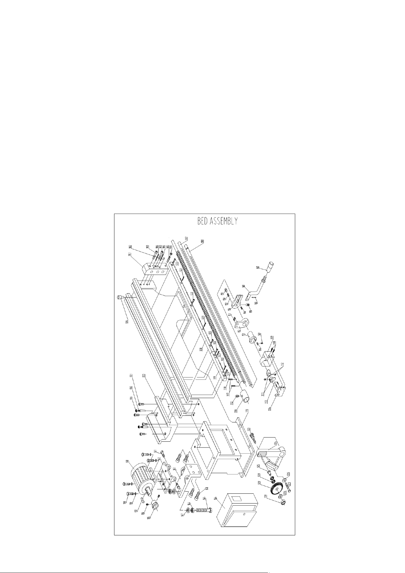
7.1 Bed Assembly
Index No.
Part No.
Description
QTY.
101
CM1224C-01-011
Fixing block
1
102
JB/T7940.4
Oil cup 6
2
103
GB/T70
Screw M8×25
2
104
GB/T879
Spring pin 5×25
2
105
GB/T77
Screw M8×20
1
106
GB/T41
Nut M8
1
107
CM1237CHG-01-009
Feeding rod
1
108
CM1237CHG-01-013
Switch lever
1
109
CM1224C-01-015
Switch cover
1
110
GB/T65
Screw M6×12
2
111
CM1224C-01-014
Eccentric block
2
112
GB/T77
Screw M6×6
3
113
GB/T70
Screw M6×12
2
114
CM1224C-01-016
Switch board
1
115
CM1237CHG-01-010
Bed
1
116
CM1224C-01-005
Sleeve
1
117
GB/T879
Spring pin 5×30
2
118
CM1237CHG-01-006
Longitudinal lead screw
1
119
CM1237CHG-01-007(2)
Rack (left)
1
120
CM1237CHG-01-007(1)
Rack (right)
1
121
GB/T70
Screw M6×20
5
122
GB/T879
Spring pin 5×30
4
123
CM1224C-01-002
Change gear shaft
1

124
CM1224C-01-001
Change gear bracket
1
125
CM1224C-01-003
Bearing sleeve
1
126
GB/T95
Washer 10
2
127
GB/T5780
Bolt M10×40
1
128
GB/T276
Bearing 6003-Z
2
129
CM1224C-01-004
Change gear
1
130
GB/T41
Nut M10
1
131
GB/T70
Screw M10×34
4
132
GB/T881
Taper pin with thread 8×75
2
133
CM1237CHG-01-010(1)
Gap
1
134
CM1224C-01-017
Stop pin
1
135
CZ1237G-02-059
Motor pulley
1
136
GB/T77-85
Screw M6×8
2
137
GB/T1096-79
Key 8×25
1
138
GB/T5780
Bolt M8×25
4
139
GB/T96
Washer 8
4
140
Y90L-4
Motor 1.5kw
1
141
CM1224C-02-042
Bolt
2
142
CM1224C-02-005
Motor seat
1
143
CM1224C-02-006
Motor rest
1
144
CZ1237A-00-001
Puller cover
1
145
GB/T5783
Bolt M12×90
1
146
GB/T6172
Nut M12
2
147
GB/T96
Washer 12
2
148
GB/T70-85
Screw M8×30
4
149
GB/T879
Spring pin 3×5
1
150
GB/T1096
Key B5×18
1
151
CM1224-06-005
Sleeve
1
152
CM1224-02-002
Arm
1
153
GB/T70
Screw M6×12
2
154
CM1224-07-004
Spring 1×6×22
1
155
GB/T78
Screw M8×12
1
156
CM1224-07-003
Cover
1
157
GB/T308
Steel ball 6
1
158
CM1224-07-006
Spring 1×6×9
1
159
GB/T77
Screw M8×10
1
160
CM1224-07-001
Lever
1
161
GB/T119
Pin B5×35
1
162
GB/T4141.14
Grip
1

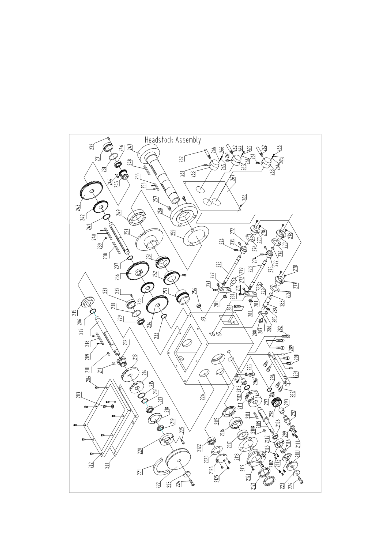
7.2 Headstock Assembly
Index No.
Part No.
Description
QTY.
201
CZ1237G-02-055
Gasket
1
202
CZ1237A-02T01-001
Cover
1
203
CM1224C-03-034
Oil fill plug
1
204
GB/T70
Screw M6×25
8
205
CZ1237G-02-024
Round fork
1
206
GB/T894.2
Retaining ring (external) 25
1
207
CZ1237G-02-025
Input shaft
1
208
GB/T1096
Key 8×80
209
GB/T65
Screw M3×8
2
210
GB/T1096
Key 5×14
1
211
GB/T1096
Key 8×20
1
212
CZ1237G-02-022
Gear
1
213
CZ1237G-02-021
Gear
1
214
CZ1237G-02-020
Gear
1
215
GB/T894.2
Retaining ring (external) 38
1
216
GB/T894.2
Retaining ring (external) 25
1
217
GB/T276
Bearing 6205P6
1
218
CZ1237G-02-017
Gasket
1
219
GB/T9877.1
Oil seal B25×40×7
1
220
CZ1237G-02-015
Cover
1
221
GB/T1174
B-Belt B914
1
222
CZ1237G-02-060
Pulley
1
223
CM1224C-03-008
Washer
2
224
GB/T70
Screw M6×14
2
225
GB/T70
Screw M6×20
3
226
CZ1237G-02-002
Headstock
1
229
GB/T276
Bearing 6204P6
1

230
GB/T7757.2
O-Ring gasket 43.7×1.8
2
231
CZ1237G-02-026
Plug
2
232
GB/T71
Screw M6×10
2
233
GB/T894.2
Retaining ring (external) 25
1
234
CZ1237G-02-013
Gear
1
235
CZ1237G-02-014
Gear
1
236
CZ1237G-02-23
Gear
1
237
GB/T894.2
Retaining ring (external) 25
1
238
GB/T1096
Key 8×80
1
239
GB/T65
Screw M3×8
2
240
GB/T1097
Key 8×80
1
241
Gb/t894.2
Retaining ring (external) 38
1
242
CZ1237G-02-028
Gear
1
243
CZ1237G-02-027
Gear
1
244
GB/T1096
Key 8×20
1
245
CZ1237G-02-029
Gear
1
246
GB/T276
Bearing 6204P6
1
247
CZ1237G-02-034
Spindle
1
248
GB/T1096
Key 8×80
1
249
GB/T297
Bearing 30211P5
1
250
CZ1237G-02-031
Gear
1
251
CZ1237G-02-033
Gear
1
252
CZ1237G-02-032
Gear
1
253
CZ1237G-02-037
Gear
1
254
GB/T1160
Oil level indicator
1
255
GB/T1096
Key 8×70
1
256
GB/T65
Screw M6×8
1
257
GB/T70
Screw M8×30
3
258
CZ1237G-02-035
Cover
1

259
CZ1237G-02-030
Gasket
1
261
GB/T78
Screw M8×14
3
262
CZ1237G-02-046
Handle
3
263
CZ1237G-02-045
Handle seat
3
264
GB/T308
Steel ball
3
265
GB/T2089
Spring 1×5×20
3
266
GB/T73
Screw M8×5
3
267
CZ1237G-02T01-006
Name plate
1
268
GB/T818
Screw M4×8
4
271
GB/T71
Screw M6×10
4
272
GB/T7757.2
O-Ring gasket
4
273
CZ1237G-02T01-005
Shaft
2
274
GB/T71
Screw M6×10
4
275
CZ1237G-02-054
Collar
2
276
CZ1237G-02-047
Gasket
3
277
CZ1237G-02-044
Fixing seat
3
278
GB/T819
Screw M5×10
6
279
CZ1237G-02-040
Fork
2
280
CZ1237G-02-039
Arm
2
281
GB/T894.2
Retaining ring (external) 15
2
282
GB/T70
Screw M10×35
6
283
GB/T7757.2
O-Ring gasket
1
284
CZ1237G-02T01-003
Shaft
1
285
GB/T894.2
Retaining ring (external) 10
1
286
CZ1237G-02-049
Arm
1
287
GB/T879
Spring pin 4×20
1
288
CZ1237G-02-050
Fork
1
289
GB/T119
Pin 8×26
2
290
GB/T70
Screw M10×30
4

291
CZ1237G-02-001
Adjusting bar
1
292
CZ1237G-02-005
Shaft
1
293
CZ1237G-02-007
Collar
1
294
GB/T894.2
Retaining ring (external) 20
1
295
GB/T70
Screw M10×16
1
296
GB/T7757.2
O-Ring gasket 10×1.8
1
297
CZ1237G-02-008
Washer
1
298
CZ1237G-02-006
Gear
1
299
CZ1237G-02-038
Cover
1
2100
GB/T819
Screw M5×10
3
2101
CZ1237G-02-042
Gear
1
2102
GB/T822
Screw M3×10
3
2103
CZ1237G-02-038
Cover
1
2104
GB/T9877.1
Oil seal FB20×35×7
1
2105
GB/T70
Screw M5×16
3
2106
GB/T276
Bearing 61804P6
1
2107
CZ1237G-02-056
Cover
1
2108
GB/T1096
Key 5×14
2
2109
CZ1237G-02-004
Shaft
1
2110
GB/T1096
Key 8×40
1
2111
CZ1237G-02-003
Gear
1
2112
GB/T894.2
Retain ring (external) 26
1
2113
CZ1237G-02-036
Sleeve
1
2114
GB/T71
Screw M6×10
1
2115
CZ1237G-02-009
Flashing ring
1
2116
GB/T297
Bearing 32010P6
1
2117
CZ1237G-02-053
Spacer
1
2118
CZ1237G-02-016
Gasket
1
2119
CZ1237G-02-010
Cover
1
2120
GB/T70
Screw M6×14
3
2121
GB/T812
Round nut M50×1.5
2
2122
GB/T276
Bearing 6205P6
1
2123
CZ1237G-02-019
Gasket
1
2124
CZ1237G-02-011
Cover
1
2125
GB/T819
Screw M5×10
3

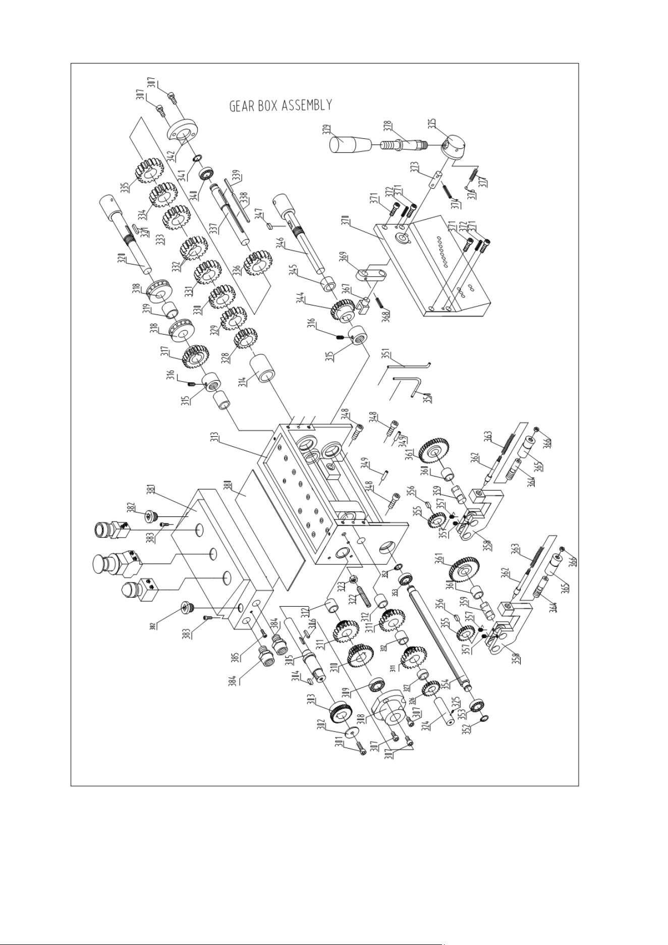
7.3 Gear Box Assembly
Index No.
Part No.
Description
Qty.
301
GB/T70
Screw M6×12
1
302
CM1224C-03-008
Washer
1
303
CM1224C-03-009
Gear
1
304
GB/T1096
Key 5×14
1
305
CM1224C-03-007
Shaft
1
306
GB/T1567
5×3×6
1
307
GB/T70
Screw M6×10
5
308
CM1224C-03-010
Bearing cover
1
309
GB/T276
Bearing 6003
1
310
CM1224C-03-013
Duplex gear
1
311
CM1224C-03-014
Duplex gear
3
312
CM1224C-03-012
Gear sleeve
3
313
CM1224C-03-033
Gear box
1
314
CM1224C-03-011
Sleeve
2
315
CM1224C-03-049
Nut
2
316
GB/T78
Screw M6×6
2
317
CM1224C-03-025
Gear
1
318
GB/T301
Bearing 51104
2
319
CM1224C-03-026
Sleeve
1
320
CM1224C-03-027
Shaft
1
321
GB/T1096
Key 6×16
2
322
GB/T73
Screw M8×35
1
323
GB/T41
Nut M8
1
324
CM1224C-03-041
Shaft
1
325
GB/T78
Screw M6×6
1
326
CM1224C-03-015
Gear
1
327
CM1224C-03-016
Gear sleeve
1

328
CM1224C-03-017
Gear
1
329
CM1224C-03-018
Gear
1
330
CM1224C-03-019
Gear
1
331
CM1224C-03-020
Gear
1
332
CM1224C-03-021
Gear
333
CM1224C-03-022
Gear
334
CM1224C-03-023
Gear
335
CM1224C-03-024
Gear
336
CM1224C-03-025
Gear
337
CM1224C-03-029
Shaft
1
338
CM1224C-03-051
Key 5×74
339
GB/T1096
Key 6×32
1
340
GB/T276
Bearing 6002-z
1
341
GB/T894.1
Retain ring (external) 15
1
342
CM1224C-03-050
Cover
1
344
CM1224C-03-032
Gear
1
345
CM1224C-03-031
Sleeve
1
346
CM1224C-03-030
Shaft
3
348
GB/T70
Screw M8×25
4
349
GB/T879
Pin 5×20
1
350
CM1224C-03-042
Oil pipe
1
351
CM1224C-03-043
Oil pipe
2
352
GB/T894.1
Retain ring
2
353
GB/T276
Bearing 6201-z
1
354
CM1224C-03-005
Shaft
2
355
CM1224C-03-006
Gear
2
356
GB/T1096
Key 5×14
4
357
GB/T77
Screw M6×6
2
358
CM1224C-03-001
Handle seat
2

359
CM1224C-03-003
Shaft
2
360
CM1224C-03-004
Gear sleeve
2
361
CM1224C-03-002
Gear
2
362
CM1224C-03-045
Axle of gripper
2
363
CM1224C-03-046
Spring
2
364
CM1224C-03-047
Sleeve of gripper
2
365
CM1224C-03-044
Lever
2
366
GB/T923
Nut M6
1
367
CM1224C-03-036
Fork
1
368
GB/T879
Pin 5×24
1
369
CM1224C-03-038
Arm
1
370
CM1224C-03-040
Front cover of gear box
4
371
GB/T70
Screw M6×16
1
272
GB/T879
Pin 5×20
2
373
CM1224C-03-039
Shaft
1
374
GB/T879
Pin 5×40
1
375
CM1224C-03-048
Knob
1
376
GB/T308
Steel ball 6
1
377
GB/T2089
Spring 1×4.5×16
1
378
CM1224C-04-003
Lever
1
379
GB/T4141.14
Lever grip BM10×50
1
380
CM1224C-03-037
Gasket
1
381
CM1224C-03-035
Knob seat
2
382
CM12224C-03-034
Plug
2
383
GB/T70
Screw M6×8
2
384
Pipe connecter 8
2

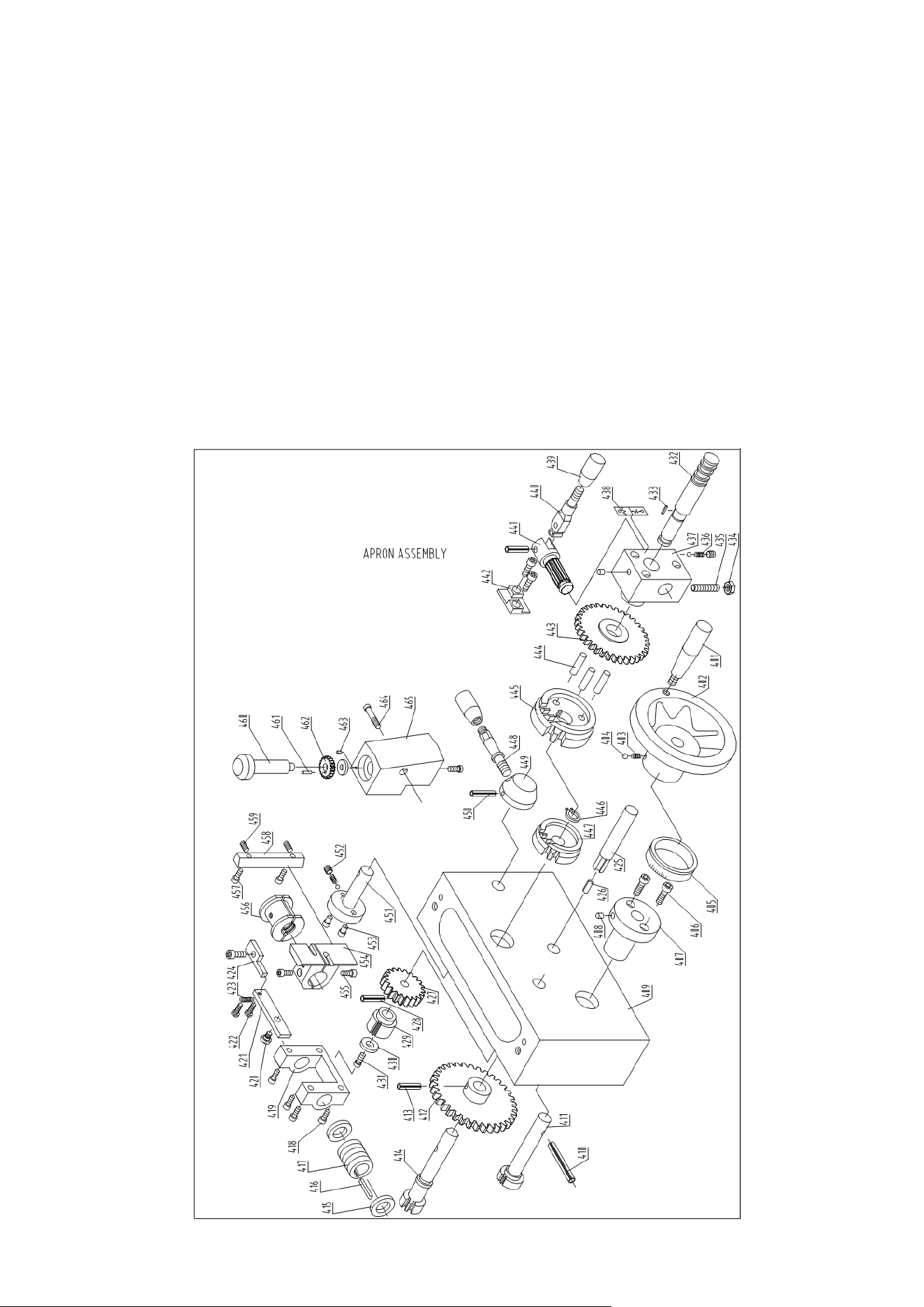
7.4 Apron Assembly
NO.
PART NO.
DESCRIPTION
QTY.
401
GB/T4141.1
Handle BM8×63
1
402
CM1224C-04-011
Handwheel
1
403
CM1224C-06-007
Spring
2
404
GB/T308
Steel ball 6
3
405
CM1224C-04-013
Dial ring
1
406
GB/T70
Screw M6×16
3
407
CM1224C-04-014
Handwheel seat
1
408
GB/T7940.4
Oiler 6
2
409
CM1224C-04-015
Apron
1
410
GB/T879
Spring Pin 5×60
1
411
CM1224C-04-012
Gear
1
412
CM1224C-04-016
Gear
1
413
GB/879
Spring pin 5×30
1
414
CM1224C-04-010
Gear shaft
1
415
CM1224C-04-037
Washer
2
416
GB/T1096
Key 5×32
1
417
CM1224C-04-022
Worm
1
418
GB/T70
Screw M6×25
4
419
CM1224C-04-021
Nut seat
1
420
GB/T830
Screw M6×6
1
421
CM1224C-04-035
Safety piece
1
422
GB/T65
Screw M4×14
2
423
CM1224C-04-034
Spring
1
424
CM1224C-04-032
Arm
1
425
CM1224C-04-007
Axle
1
426
GB/T1096
Key 4×20
1
427
CM1224C-04-006
Gear
1

428
GB/T879
Spring pin 5×24
2
429
CM1224C-04-023
Worm
1
430
CM1224C-04-031
Washer
2
431
GB/T70
Screw M6×12
4
432
CM1224C-04-020
Shaft
1
433
GB/T1096
Key 4×8
1
434
GB/T6170
Nut M8
1
435
GB/T75
Screw M8×35
1
436
CM1224C-04-038
Spring
2
437
CM1224C-04-017
Change lever seat
1
438
CM1224C-00-011
Feed plate
1
439
Gb/t4141.14
Lever grip BM10×50
1
440
CM1224C-04-001
Change lever
1
441
CM1224C-04-018
Rod
1
442
CM1224C-04-002
Safety stopper
1
443
CM1224C-04-008
Clutch gear
1
444
GB/T119
Pin A6×30
3
445
CM1224C-04-009
Clutch
1
446
GB/T894.1
Contain ring
1
447
CM1224C-04-019
Clutch gear
1
448
CM1224C-04-003
Handle
1
449
CM1224C-04-036
Knob
1
450
GB/T879
Spring pin 5×40
1
451
CM1224C-04-004
Rod
1
452
GB/T77
Screw M8×8
2
453
CM1224C-04-024
Pin
2
454
CM1224C-04-026
Half nut seat
1
455
GB/70
Screw M6×8
2
456
CM1224C-04-025
Half nut
1
457
GB/T70
Screw M5×16
2
458
CM1224C-04-029
Guide plate
1
459
GB/T78
Screw M6×12
2
460
CM1224C-04-028
Axle
1
461
GB/T119
Pin 3×12
1
462
CM1224C-04-030
Gear
1
463
GB/T827
Rivet 2.5×5
1
464
GB/T70
Screw M6×45
1
465
CM1224C-04-027
Threading dial
1

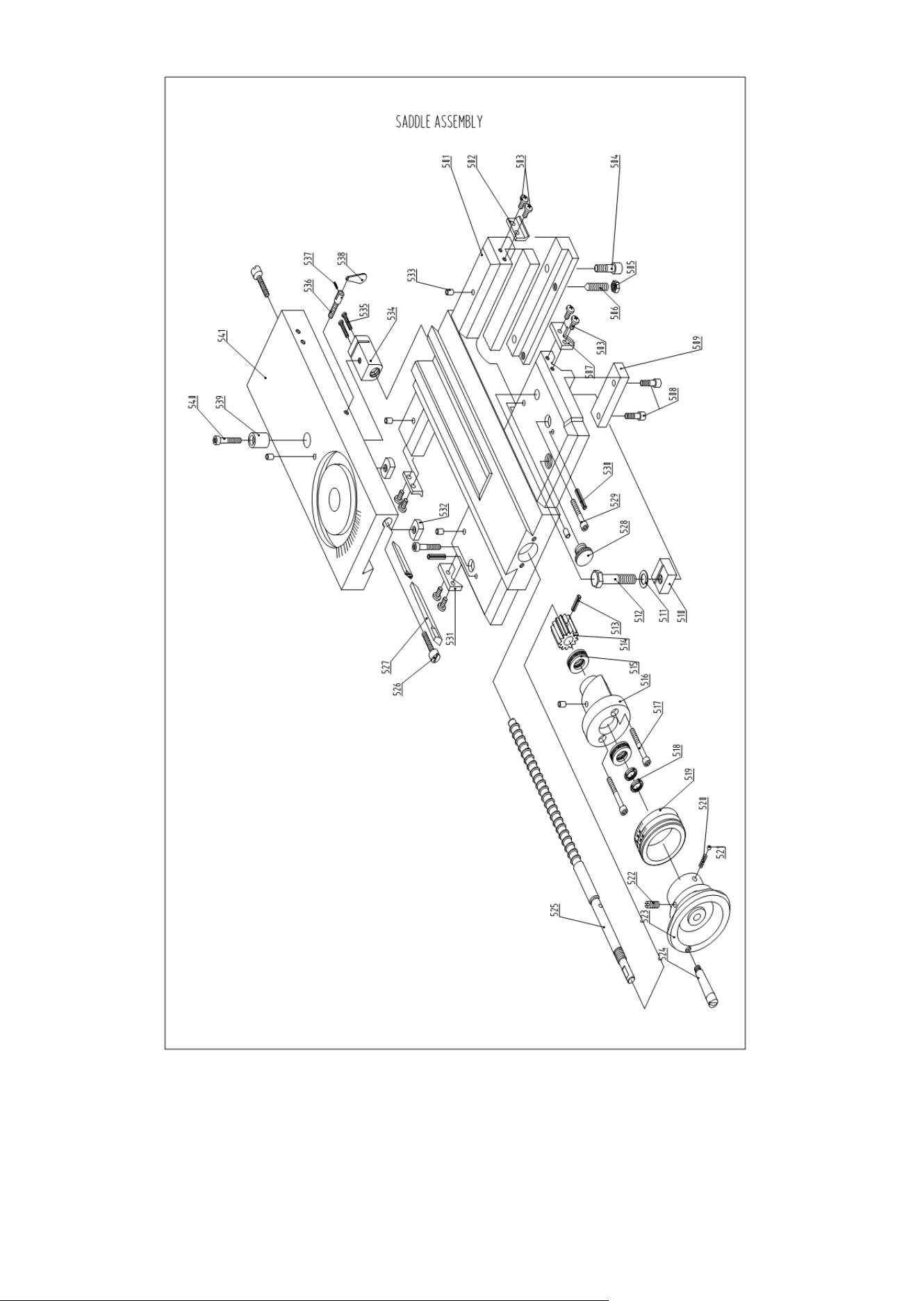
7.5 Saddle Assembly
Index No.
Part No.
Description
QTY.
501
CM1224C-05-003
Saddle
1
502
CM1224C-05-044
Wiper
2
503
GB/T818
Screw M5×12
8
504
GB/T70
Screw M8×25
3
505
GB/T41
Nut M8
3
506
GB/T78
Screw M8×22
3
507
CM1224C-05-041
Wiper
1
508
GB/T70
Screw M6×16
4
509
CM12224C-05-040
Block slide
2
510
CM1224C-05-032
Locking block
1
511
GB/T95
Washer 10
1
512
GB/T5780
Bolt M10×60
1
513
GB/T879
Pin 5×20
1
514
CM1224C-05-039
Gear
1
515
GB/T301
Bearing 51101
2
516
CM1224C-05-038
Lead screw seat
1
517
GB/T70
Screw M6×45
2
518
GB/T810
Nut M12×1.25
2
519
CM1224C-05-037
Graduation collar
1
520
CM1224C-06-007
Compressing spring
2
521
GB/T308
Steel ball 6
1
522
GB/T77
Screw M6×16
1
523
CM1224C-05-023
Handwheel
1
524
CM1224C-05-024
Handle
1
525
CM1224C-05-004
Lead screw of saddle
1
526
CM1224C-05-034
Adjusting screw
2
527
CM1224C-05-035
Gib
1

528
CM1224C-03-034
Plug
1
529
GB/T70
Screw M8×30
2
530
GB/T879
Pin 5×35
2
531
CM1224C-05-042
Wiper
1
532
CM1224C-05-008
Fixing block
2
533
JB/T7940.1
Oil cup 6
6
534
CM1224C-05-006
Lead screw nut
1
535
GB/T818
Screw M4×20
2
536
CM1224C-05-022A
Locking screw
2
537
GB/T879
Pin 2×8
2
538
CM1224C-05-022B
Locking lever
2
539
CM1224C-05-007
Fixing seat
1
540
GB/T70
Screw M6×20
1
541
CM12224C-05-005
Cross slide
1

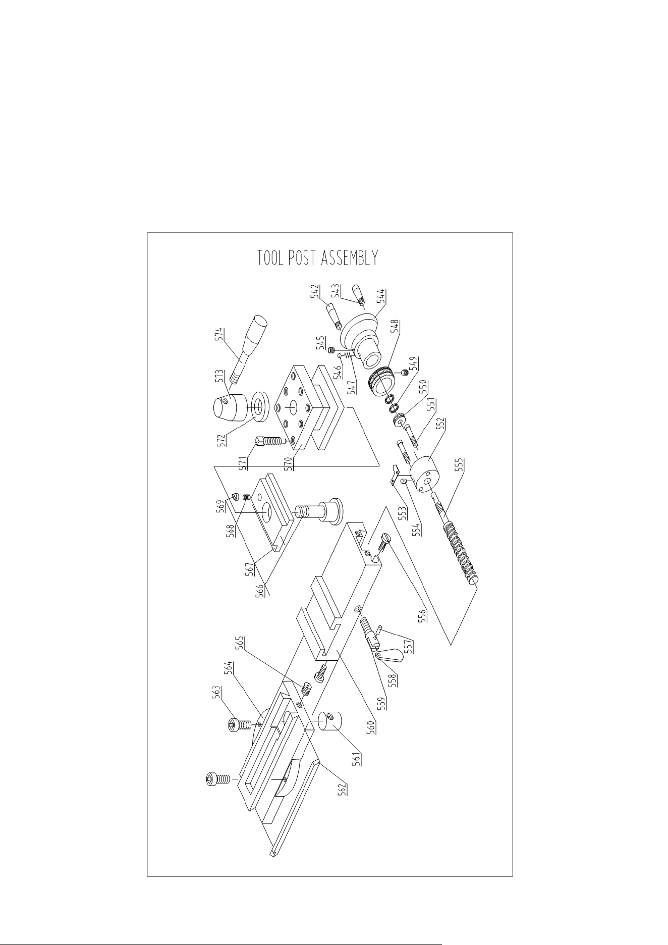
7.6 Tool post assembly
Index No.
Part No.
Description
QTY.
542
CM1224C-05-031
Handle
1
543
CM1224C-05-030
Handle
1
544
CM1224C-05-029
Handwheel
1
545
GB/T77
Screw M6×16
2
546
GB/T308
Steel ball6
1
547
CM1224C-06-007
Pressure spring
1
548
CM1224C-05-028
Graduation collar
1
549
GB/T810
Nut M10×1
2
550
GB/T301
Bearing 51100
1
551
GB/T70
Screw M4×30
2
552
CM1224C-05-027
Leadscrew seat
1
553
CM1224C-00-006
Indicator plate
1
554
JB/T7940.4
Oil cup 6
1
555
CM1224C-05-025
Leadscrew
1
556
CM1224C-05-020
Adjusting screw
2
557
GB/T879
Pin 2×8
2
558
CM1224C-05-022(B)
Clamping knob
1
559
CM1224C-05-022(A)
Clamping screw
1
560
CM1224C-05-010
Base of tool post
1
561
CM1224C-05-026
Leadscrew nut
1
562
CM1224C-05-019
Gib
1
563
GB/T70
Screw M8×24
2
564
CM1224C-05-009
Swivel base
1
565
GB/T78
Screw M6×12
1
566
CM1224C-05-016
Locking screw
1
567
CM1224C-05-043
T-block
1
568
CM1224C-05-011
Compressing spring
1
569
CM1224C-05-012
Locating block
1
570
CM1224C-05-014
Tool post
1
571
CM1224C-05-013
Screw
8
572
CM1224C-05-015
Washer
1
573
CM1224C-05-017
Lever
1
574
CM1224C-05-018
Handle
1

7.7 Follow rest assembly
Index No.
Part No.
Description
QTY.
T101
JB/T727404
Star handle M8×30
2
T102
GB/T879
Pin 3×16
2
T103
CM1224C-05T02-003
Collar
2
T104
CM1224C-05T02-002
Adjusting screw
2
T105
CM1224C-05T02-004
Sleeve
2
T106
CM1224C-05T02-005
Clamping block
2
T107
GB/T78
Screw M6×8
2
T108
GB/T71
Screw M6×16
2
T109
GB/T6170
Nut M6
2
T110
GB/T70
Screw M8×35
2
T111
CM1224C-05T02-002
Follow rest
1

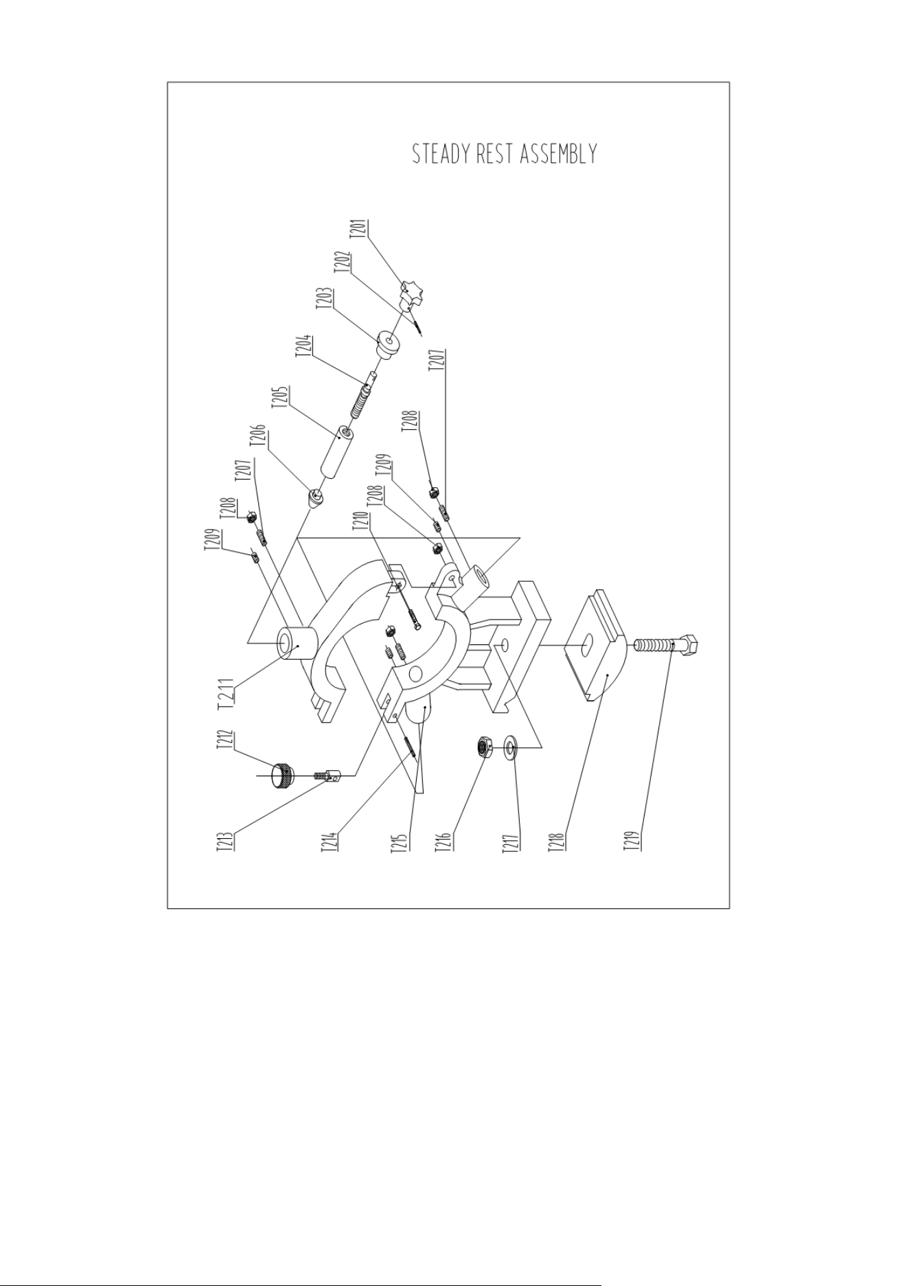
7.8 Steady rest assembly
Index No.
Part No.
Description
QTY.
T201
JB/T7274.4
Star handle M8×30
3
T202
GB/T879
Pin 3×16
3
T203
CM1224C-05T02-003
Collar
3
T204
CM1224C-05T02-002
Adjusting screw
3
T205
CM1224C-05T02-004
Sleeve
3
T206
CM1224C-05T02-005
Clamping block
3
T207
GB/T71
Screw M6×16
3
T208
GB/T6170
Nut M6
4
T209
GB/T78
Screw M6×8
3
T210
GB/T27
Bolt M6×25
3
T211
CM1224C-05T03-003
Cover of steady rest
1
T212
CM1224C-05T03-002
Knob
1
T213
CM1224C-05T03-001
Lever
T214
GB/T879
Pin 5×30
1
T215
CM1224C-05T03-004
Base of steady rest
1
T216
GB/T41
Nut M12
1
T217
GB/T95
Washer 12
1
T218
CM1224C-06-018
Fixing plate
1
T219
GB/T5780
Bolt M12×70
1
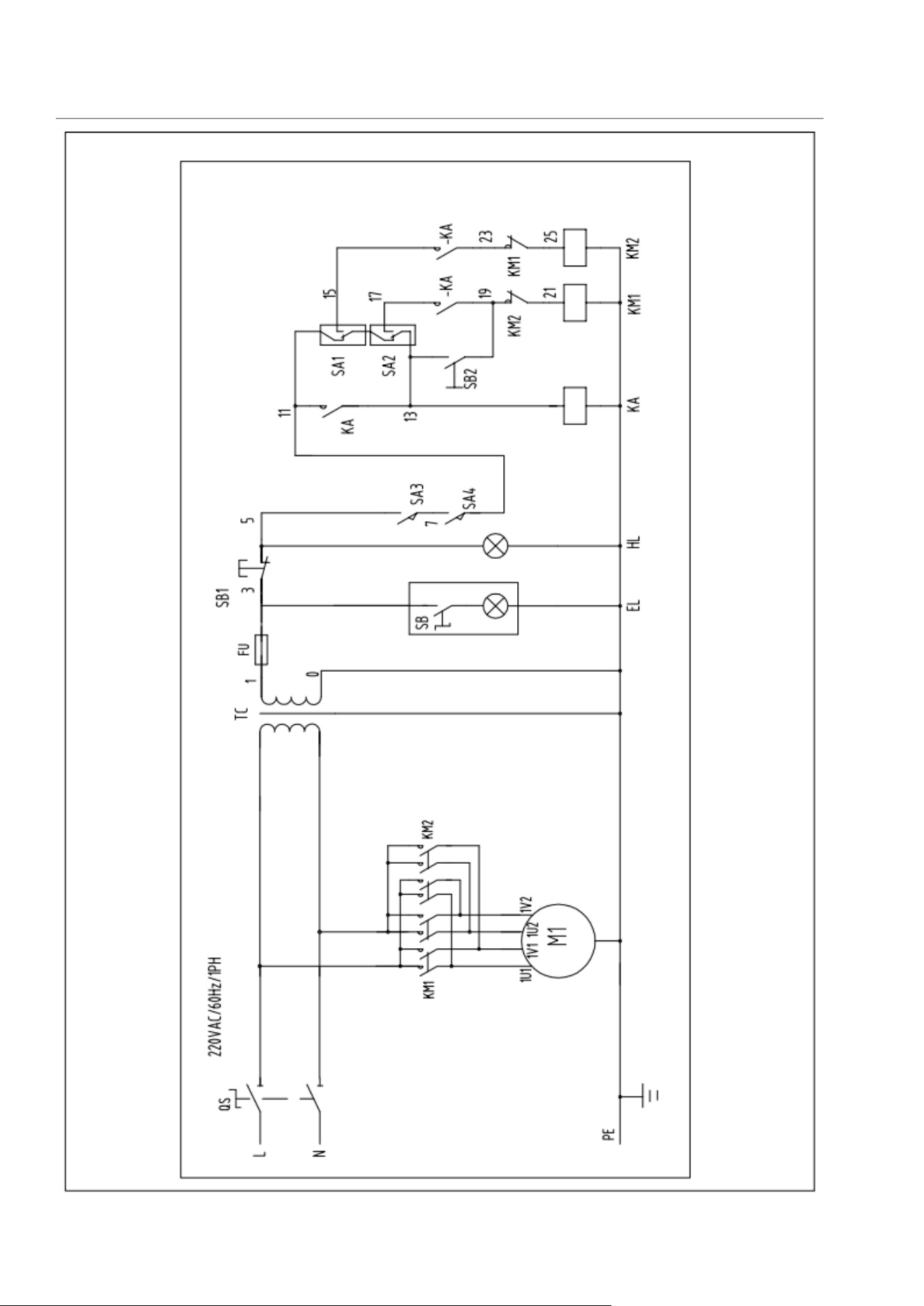
8. ELECTRICAL SCHEMATIC
