
2200 PSI / 1.2 GPM
ELECTRIC PRESSURE WASHER
GPW 2200
Read all safety rules and instructions carefully before operating this tool.
www.greenworkstools.com
OPERATOR’S MANUAL
TOLL-FREE HELPLINE:
1-855-345-3934

EN - 2
INSTRUCTION
Important Safety Instructions………………………………………………………........................................3
Specific Safety Rules……………………………………………………………….........................................5
Symbols……………………………………………………………………………….........................................7
Electrical………………………………………………………………………………........................................9
Know Your Pressure Washer…………………………………………………………......................................10
Packing List..............................................................................................................................................11
Assembly……………………………………………………………………………….....................................12
Operation……………………………………………………………………………….....................................17
Maintenance………………………………………………………………………….......................................22
Troubleshooting………………………………………………………………………......................................25
Warranty……………………………………………………………………………………...............................28
Exploded View…………………………………………………………………………................................….29
Parts List………………………………………………………………………………......................................30
PRODUCT SPECIFICATION
Induction Motor………………………………………………………........................................Brushless motor
Power Cord with In-Line GFCI................................................................................................................35ft
Max. Pounds Per Square Inch Pressure…………………………………….......................................2200psi
Rated Gallons Per Minute………………………………………….....……….....................................1.2 GPM
Max Gallons Per Minute at 100PSI…………………………………….....………..............................2.3 GPM
Maximum Inlet Water Temperature……………………………………………..……................104°F(40℃)
Cleaning Units...............................................................................................................................2640 C.U
Net Weight……………………………………………………………...................................................19.82 Kg

EN - 3
IMPORTANT SAFETY INSTRUCTIONS
W A R N I N G
Read and understand all instructions. Failure to follow all instructions listed below may result. in electric
shock, re, and/or serious personal injury.
W A R N I N G
When using this product, basic precautions should always be followed.
READ ALL INSTRUCTIONS BEFORE USING THIS PRODUCT
■ To reduce the risk of injury, close supervision is necessary when a product is used near children.
■ Be thoroughly familiar with controls. Know how to stop the product and release pressure quickly.
■ Stay alert and exercise control. Watch what you are doing and use common sense. Do not operate
product when you are tired. Do not rush.
■ Do not operate the product while under the influence of drugs, alcohol, or any medication.
■ Keep the area of operation clear of all people, particularly small children, and pets.
■ Don’t overreach or stand on unstable support. Keep proper footing and balance at all times.
■ Follow the maintenance instructions specified in this manual.
W A R N I N G
Risk of injection or injury – Do not direct discharge stream at people or animals.
GROUND FAULT CIRCUIT INTERRUPTER PROTECTION
This pressure washer is provided with a ground fault circuit interrupter (GFCI) built into the plug of the
power supply cord. This device provides additional protection from the risk of electric shock. Should
replacement of the plug or cord become necessary, use only identical replacement parts that include
GFCI protection.
W A R N I N G
To reduce the risk of electrocution, keep all connections dry and off the ground. Do not touch plug with
wet hands.

EN - 4
IMPORTANT SAFETY INSTRUCTIONS
EXTENSION CORDS
When using a power tool at a considerable distance from a power source, be sure to use an extension
cord that has the capacity to handle the current the product will draw. An undersized cord will cause a
drop in line voltage, possibly resulting in overheating, loss of power, and/or circuit breaker or GFCI
tripping. Use the chart to determine the minimum wire size required in an extension cord. Only round
jacketed cords listed by Underwriter’s Laboratories (UL) should be used.
When working outdoors with a product, use an extension cord that is designed for outside use. This type
of cord is designated with “WA” or “W” on the cord’s jacket.
Before using any extension cord, inspect it for loose or exposed wires and cut or worn insulation.
It is possible to tie the extension cord and power cord in a knot to prevent them from becoming
disconnected during use. Make a knot, then connect the plug end of the power cord into the receptacle
end of the extension cord. This method can also be used to tie two extension cords together.
USE ONLY THIS SIZE EXTENSION CORD WHEN USING THIS PRODUCT:
Cord Length Wire Size (A.W.G.)
25 ft. 12
50 ft. Not Allowed
100 ft. Not Allowed
W A R N I N G
Keep the extension cord clear of the working area. Position the cord so that it will not get caught on lumber, tools, or other
obstructions while you are working with a power tool. Failure to do so can result in serious personal injury.
W A R N I N G
Check extension cords before each use. If damaged replace immediately. Never use the product with a damaged cord
since touching the damaged area could cause electrical shock resulting in serious injury.

EN - 5
SPECIFIC SAFETY RULES
■ Know your product. Read the operator’s manual carefully. Learn the machine’s applications and
limitations as well as the specic potential hazards related to this product.
■ To reduce the risk of injury, keep children and visitors away. All visitors should keep a safe
distance from the work area.
■ Use the right product for the job. Don’t force the product or the attachments to do a job it was not
designed for. Don’t use it for a purpose not intended.
■ Dress properly. Do not wear loose clothing, gloves, neckties, or jewellery. They can get caught and
draw you into moving parts. Rubber gloves and non-skid footwear are recommended when working
outdoors. Also wear protective hair covering to contain long hair.
■ Do not operate the equipment while barefoot or when wearing sandals or similar lightweight
footwear. Wear protective footwear that will protect your feet and improve your footing on slippery
surfaces.
■ Exercise caution to avoid slipping or falling.
■ Always wear eye protection with side shields marked to comply with ANSI Z87.1. Following
this rule will reduce the risk of serious personal injury.
■ Use only recommended accessories. The use of improper accessories may cause risk of injury.
■ Check damaged parts. Before further use of the product, all parts should be carefully checked to
determine that they will operate properly and perform their intended function. Check for alignment of
moving parts, binding of moving parts, breakage of parts, mounting, and any other conditions that
may affect its operation. A guard or other part that is damaged must be properly repaired or replaced
by an authorized service center to avoid risk of personal injury.
■ Never leave product running unattended. Turn power off. Don’t leave the product until it comes to
a complete stop.
■ Keep the motor free of grass, leaves, or grease to reduce the chance of a re hazard.
■ Follow manufacturer’s recommendations for safe loading, unloading, transport, and storage
of machine.
■ Keep product dry, clean, and free from oil and grease. Always use a clean cloth when cleaning.
Never use brake uids, gasoline, petroleum-based products, or any solvents to clean product.
■ Check the work area before each use. Remove all objects such as rocks, broken glass, nails,
wire, or string which can be thrown by the machine.
■ Do not use product if switch does not turn it off. Have defective switches replaced by an
authorized service center.
■ Avoid dangerous environment. Don’t expose to rain. Keep work area well lit.
■ Do not abuse the cord. Never use the cord to carry the product or to disconnect the plug from
an outlet. Keep cord away from heat, oil, sharp edges, or moving parts. Replace damaged cords
immediately. Damaged cords increase the risk of electric shock.
■ Ground Fault Circuit Interrupter (GFCI) protection should be provided on the circuit (s) or
outlet (s) to be used for the product. Receptacles are available having built-in GFCI protection
and may be used for this measure of safety.
■ Never direct a water stream toward people or pets, or any electrical device.
■ Before starting any cleaning operation, close doors and windows. Clear the area to be cleaned
of debris, toys, outdoor furniture, or other objects that could create a hazard.
■ Do not use acids, alkalines, solvents, ammable material, bleaches, or industrial grade
solutions in this product. These products can cause physical injuries to the operator and
irreversible damage to the machine.

EN - 6
SPECIFIC SAFETY RULES
W A R N I N G
High pressure jets can be dangerous if subject to misuse. The jet must not be directed at people,
animals, electrical devices, or the machine itself.
■ Keep the motor away from ammables and other hazardous materials.
■ Check bolts and nuts xing the pressure washer shell for looseness before each use. A loose
bolt or nut may cause serious motor problems.
■ Before storing, allow the motor to cool.
■ When servicing use only identical replacement parts. Use of any other parts may create a
hazard or cause product damage.
■ ONLY use cold water.
■ Make sure minimum clearance of 3 feet is maintained from combustible materials.
■ Connect pressure washer only to an individual branch circuit.
■ Hold the handle and wand securely with both hands. Expect the trigger handle to move when
the trigger is pulled due to reaction forces. Failure to do so could cause loss of control and injury to
yourself and others.
■ Save these instructions. Refer to them frequently and use them to instruct other users. If you loan
someone this product, loan them these instructions also.
W A R N I N G
Some dust created by power sanding, sawing, grinding, drilling, and other construction activities
contains chemicals known to cause cancer, birth defects or other reproductive harm. Some examples of
these chemicals are:
• Lead from lead-based paints
• Crystalline silica from bricks and cement and other masonry products
• Arsenic and chromium from chemically treated lumber
Your risk from these exposures varies, depending on how often you do this type of work. To reduce your
exposure to these chemicals: work in a well ventilated area, and work with approved safety equipment,
such as those dust masks that are specially designed to lter out microscopic particles.
W A R N I N G
This product contains chemical(s) including lead, known to the State of California to cause cancer, birth
defects, and other reproductive harm. Do not drink water from this hose. Wash hands after use.
EN - 7
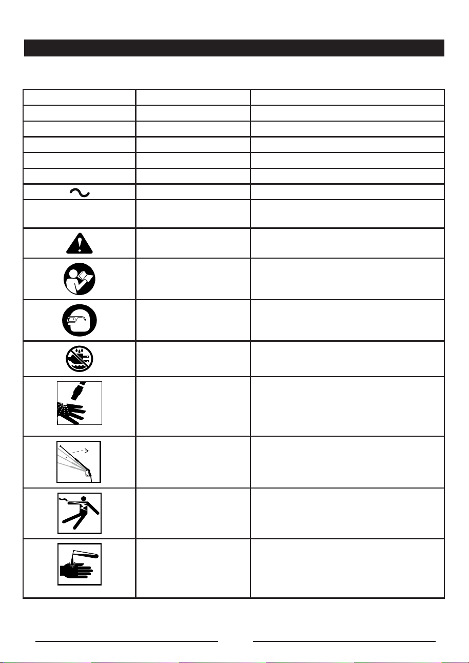
SYMBOLS
Some of the following symbols may be used on this product. Please study them and learn their meaning.
Proper interpretation of these symbols will allow you to operate the product better and safer.
SYMBOL NAME DESIGNATION/EXPLANATION
V Volts Voltage
A Amperes Current
Hz Hertz Frequency (cycles per second)
W Watt Power
no No Load Speed Rotational speed, at no load
Alternating Current Type of current
.../min Per Minute
Revolutions, strokes, surface speed, orbits
etc., per minute
Safety Alert Indicates a potential personal injury hazard.
Read Operator’s Manual
To reduce tthe risk of injury, user must read
and understand operator’s manual before
using this product.
Eye Protection
Always wear eye protection with side shields
marked to comply with ANSI Z87.1.
Wet Conditions Alert
Do not expose to rain or use in damp
locations.
Risk of Injection
To reduce the risk of injection or injury, never
direct a water system towards people or pets
or place any body part in the stream. Leaking
hoses and fittings are also capable of causing
injection injury. Do not hold hoses or fittings.
Kickback
To reduce the risk of injury from kickback,
hold the spray wand securely with both hands
when the machine is on.
Electric Shock
Failure to use in dry conditions and to
observe safe practices can result in electric
shock.
Chemical Burns
To reduce the risk of injury or damage, DO
NOT USE ACIDS, ALKALINES, BLEACHES,
SOLVENTS, FLAMMABLE MATERIAL, OR
INDUSTRIAL GRADE SOLUTIONS in this
product.
EN - 8
SYMBOLS
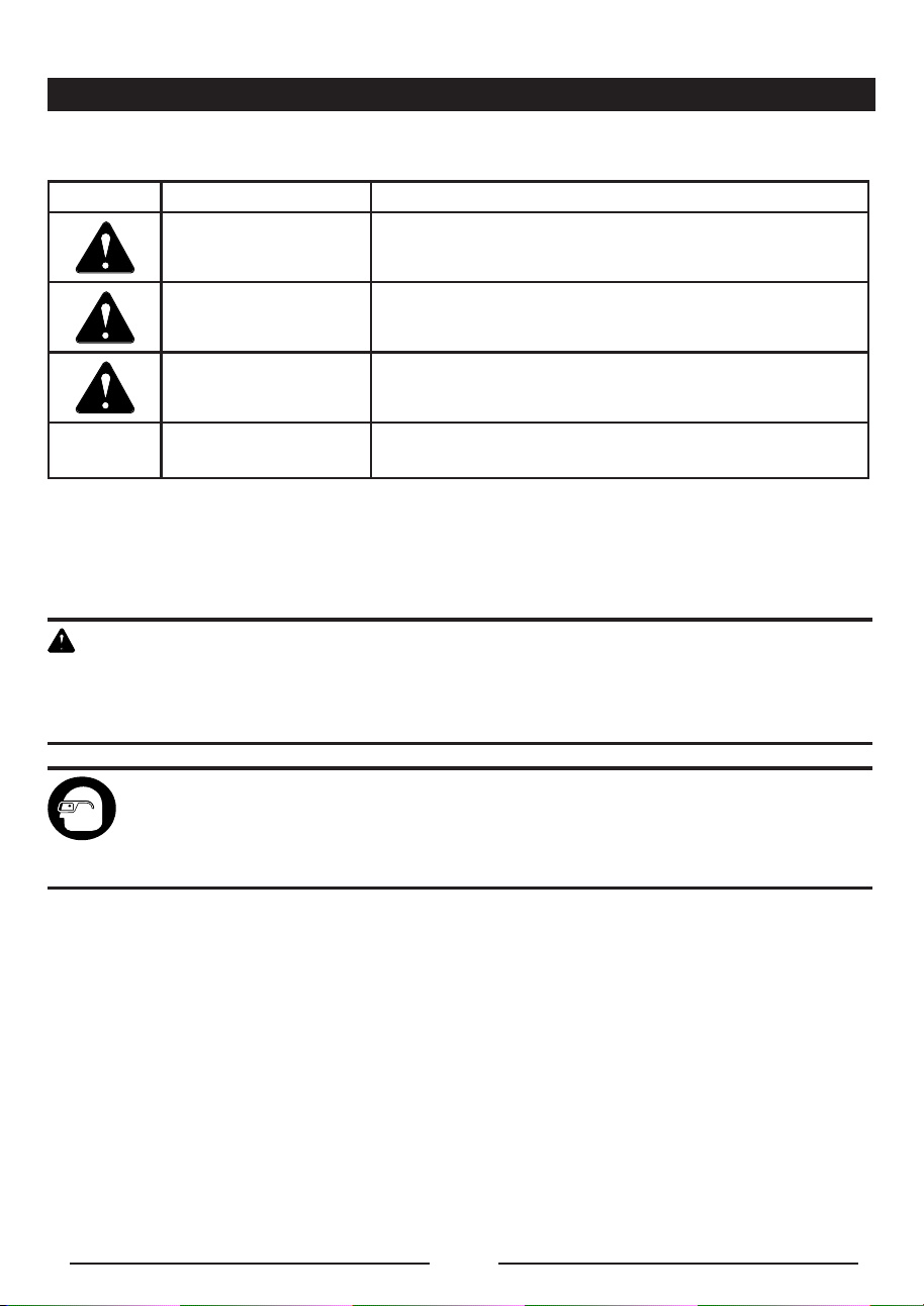
The following signal words and meanings are intended to explain the levels of risk associated
with this product.
SYMBOL SIGNAL MEANING
DANGER
Indicates an imminently hazardous situation, which, if not
avoided, will result in death or serious injury.
WARNING
Indicates a potentially hazardous situation, which, if not
avoided, could result in death or serious injury.
CAUTION
Indicates a potentially hazardous situation, which, if not
avoided, may result in minor or moderate injury.
CAUTION
(Without Safety Alert Symbol) Indicates a situation that may
result in property damage.
SERVICE
Servicing requires extreme care and knowledge and should be performed only by a qualied
service technician. For service, return the product to your nearest AUTHORIZED
SERVICE CENTER for repair. When servicing, use only identical replacement parts.
W A R N I N G
To avoid serious personal injury, do not attempt to use this product until you read thoroughly and
understand completely the operator’s manual. If you do not understand the warnings and instructions in
the operator’s manual, do not use this product. Call GREENWORKS customer service for assistance.
The operation of any power tool can result in foreign objects being thrown into your eyes,
which can result in severe eye damage. Before beginning power tool operation, always wear
safety goggles or safety glasses with side shields and, when needed, a full face shield. We
recommend Wide Vision Safety Mask for use over eyeglasses or standard safety glasses
with side shields. Always use eye protection which is marked to comply with ANSI Z87.1.
EN - 9
ELECTRICAL
ELECTRICAL CONNECTION
This product has a precision-built brushless motor. It should be connected to a power supply that is 120
volts, 60 Hz, AC only (normal household current). Do not operate this product on direct current (DC). A
substantial voltage drop will cause a loss of power and the motor will overheat.
If the product does not operate when plugged into an outlet, double check the power supply.
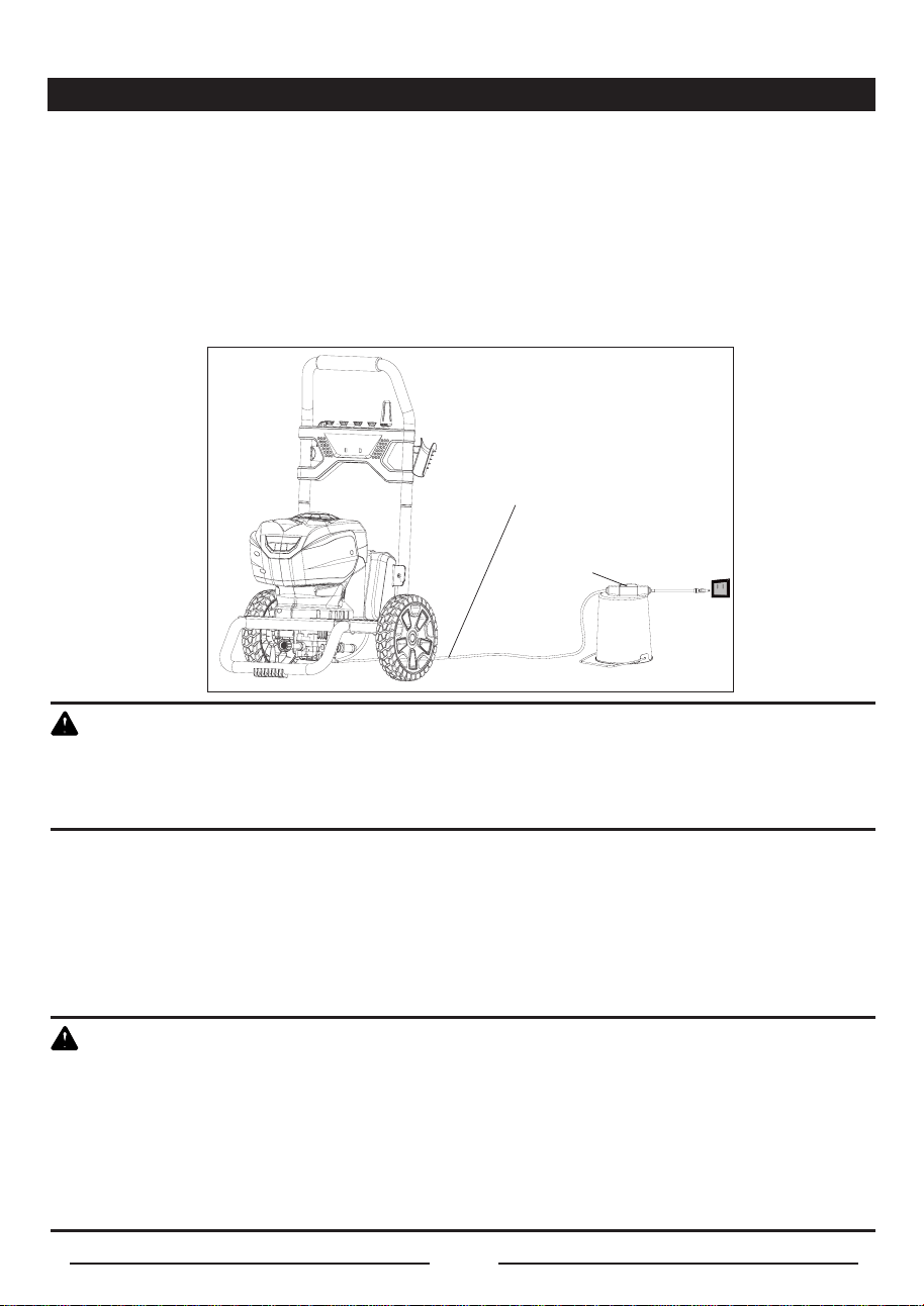
DRIP LOOP
(See Figure 1.)
To prevent water from flowing along the power cable, and possibly reaching the electrical outlet and
plug, we recommend using a simple drip loop as shown below.
W A R N I N G
Keep the extension cord clear of the working area. Position the cord so that it will not get caught on
lumber, tools, or other obstructions while you are working with a power tool. Failure to do so can result
in serious personal injury.
GROUND FAULT CIRCUIT INTERRUPTER
This unit is equipped with a Ground Fault Circuit Interrupter (GFCI), which guards against the hazards
of ground fault currents. An example of ground fault current is the current that would ow through a
person who is using an appliance with faulty insulation and, at the same time, is in contact with an
electrical ground such as a plumbing xture, wet oor, or earth.
GFCI plugs do not protect against short circuits, overloads, or shocks.
W A R N I N G
The GFCI plug can be tested with the TEST and RESET buttons.
● Plug into receptacle.
● Press the TEST button. You will hear a “click” sound and the red LED light will go out.
● Press the RESET button. The LED light will illuminate to indicate power has been restored.
Perform this test monthly to ensure proper operation of the GFCI.
To reduce the risk of electric shock the supervisory circuit must be operated before an appliance is
plugged into any receptacle on the device.
Fig. 1
Power Cord
Drip Loop
EN - 10
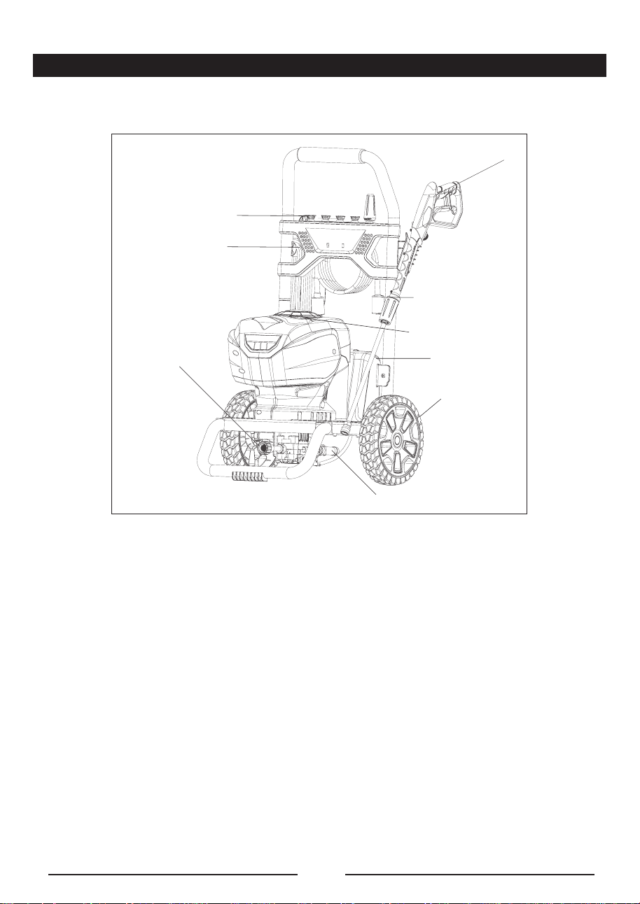
KNOW YOUR PRESSURE WASHER
The safe use of this product requires an understanding of the information on the tool and in this
operator’s manual as well as a knowledge of the project you are attempting. Before use of this product,
familiarize yourself with all operating features and safety rules. (See Figure 2.)
DETERGENT TANK
Remove the cap from the detergent tank to add detergent to the pressure washer.
GFCI PLUG
The pressure washer is equipped with a GFCI plug to guard against the hazards of ground fault
currents. This plug does not protect against short circuits, overloads, or shocks.
HIGH PRESSURE HOSE STORAGE
A convenient hose hook stores the high pressure hose when the pressure washer is not in use.
AUTO ON/OFF SWITCH:
This pressure washer is equipped with an Auto Start/Stop feature. To operate: Rotate power switch
to the On (I) position. Pump will pressurize and shut down immediately. Once the trigger of the gun is
depressed the unit will turn on. Unit will shut off and be in standby mode when trigger is released.
POWER CORD STORAGE
The power cord can be wrapped and stored around the hooks.
TRIGGER AND WAND ASSEMBLY
The Trigger and Wand allows you to operate the pressure washer by depressing the trigger to activate
the pump to spray water using the desired spray tip.
WATER INTAKE
Attach the garden hose to the water intake.
WATER OUTLET
Attach the High Pressure Hose to the water outlet.
ON/OFF Switch
Power Cord Storage
Trigger and Wand
Assembly
High Pressure Hose
Detergent Tank
Wheel
Fig. 2
Tip Storage
Water Intake
Water Outlet
EN - 11
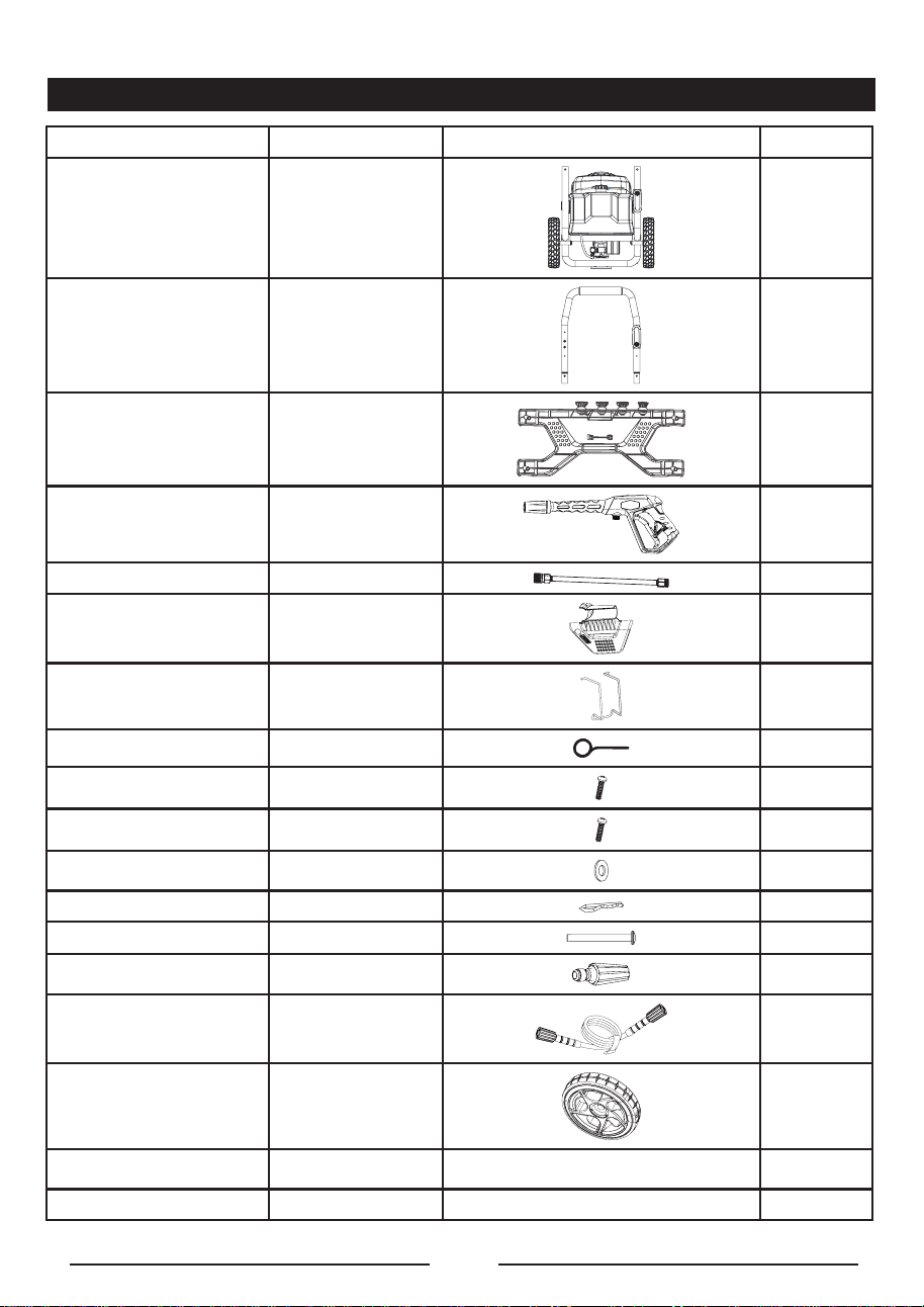
PACKING LIST
PART NAME ERP NO. FIGURE PART NO.
• Pressure Washer
1
• Upper Handle Assembly
(including the spray tips)
311201936
1
• Front panel assembly
(spray tip included)
341001936
1
• S p r a y e r g u n ( t r i g g e r ) 31140636-1
1
• Wand assy 31145363 1
• Gun Holder 341101936
1
• Hose Hook 333011936
1
• Spray Tip Cleaning Tool 33201671
1
• Screw 322011628 4
• Screw 322011635
2
• Washer 32908301A
4
• Pin 32229301A 2
• Axle
332201936 2
• Turbo Nozzle
31208363 1
• High Pressure Hose
311311635 1
• Wheels 3110301936 2
• Operator’s Manual 388011936 1
• Quick Start Guide 388021936 1

EN - 12
ASSEMBLY
UNPACKING
This product requires assembly.
■ Carefully remove the product and any accessories from the box. Make sure that all items listed in
the packing list are included.
W A R N I N G
Do not use this product if any parts on the Packing List are already assembled to your product when
you unpack it. Parts on this list are not assembled to the product by the manufacturer and require
customer installation. Use of a product that may have been improperly assembled could result in
serious personal injury.
■ Inspect the product carefully to make sure no breakage or damage occurred during shipping.
■ Do not discard the packing material until you have carefully inspected and satisfactorily operated
the product.
■ If any parts are damaged or missing, please call 1-855-345-3934 for assistance.
W A R N I N G
If any parts are damaged or missing do not operate this product until the parts are replaced. Use of this
product with damaged or missing parts could result in serious personal injury.
W A R N I N G
Do not attempt to modify this product or create accessories not recommended for use with this
product. Any such alteration or modification is misuse and could result in a hazardous condition leading
to possible serious personal injury.
W A R N I N G
Do not connect to power supply until assembly is complete. Failure to comply could result in accidental
starting and possible serious personal injury.
EN - 13
ASSEMBLY
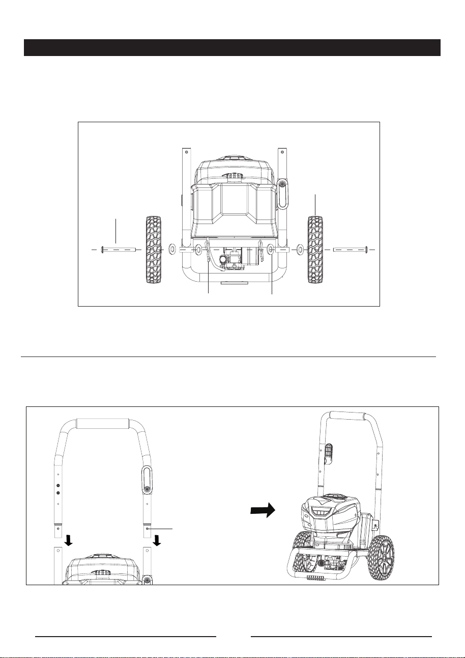
ASSEMBLING THE WHEEL (See Figure 3.)
■ Insert the axle through the wheel and through the frame.
■ Slide the washer over the axle pass the pin hole.
■ Insert the pin through the hole to firmly fasten the wheel.
ASSEMBLING THE HANDLE (See Figure 4.)
■ Push and hold the push-pin button on the side of the upper handle assembly (1) as you slide the
handle onto the frame (2).
NOTE: Before use, pull the handle up until the lock button snaps through the locking slots to secure the
handle place.
Fig. 3
Axle
Wheels
Pin
Axle
Washer
Fig. 4
(1)
(2)
pin
EN - 14
ASSEMBLY
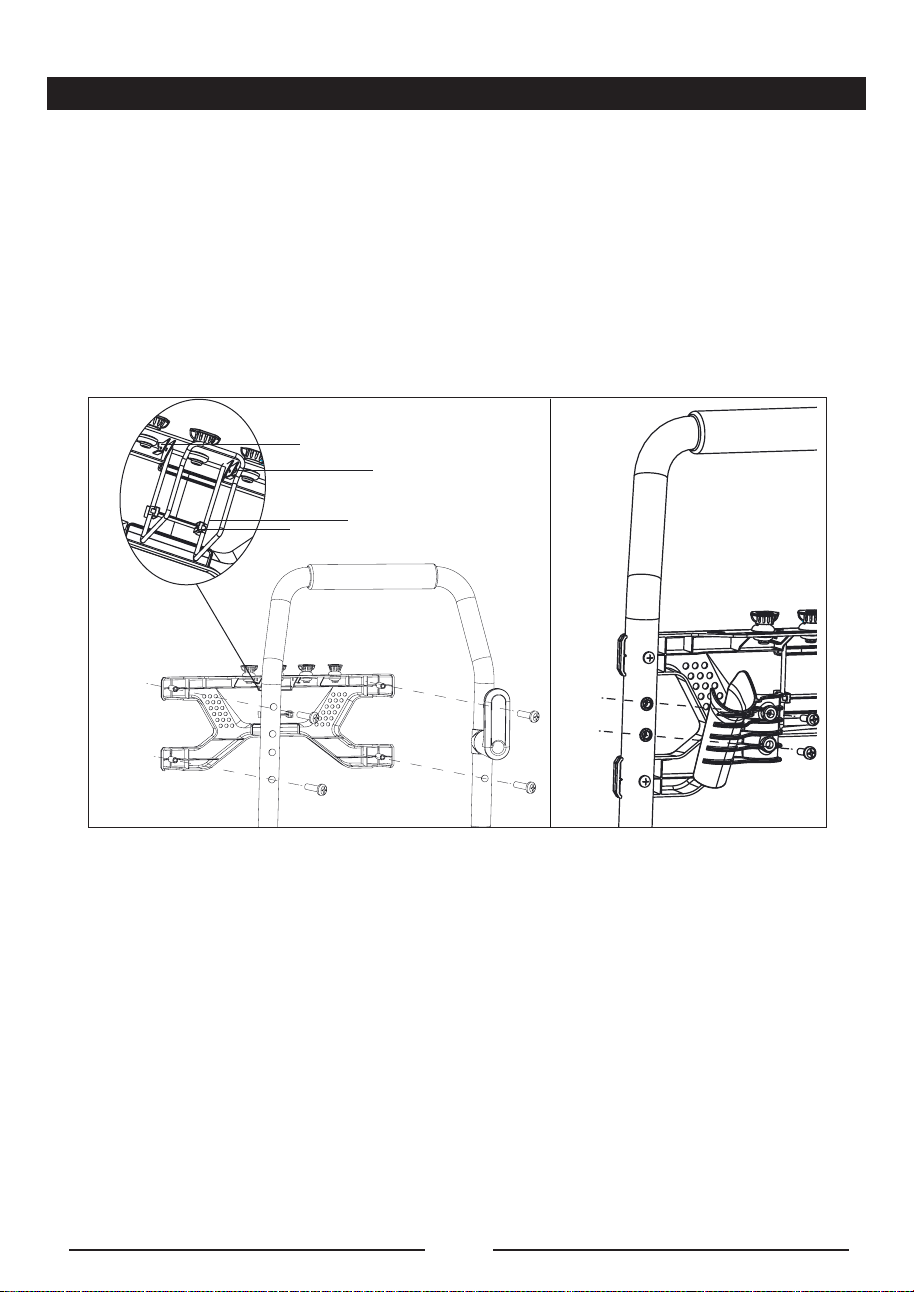
ASSEMBLING THE FRONT PANEL AND GUN HOLDER (See Figure 5.)
■ Line up the screw sleeves with the holes in the upper handle and push through.
■ Insert the screw and turn clockwise with a phillips head screw driver (not included) until the screw is
tight.
ASSEMBLING THE HOSE HOOK (See Figure 5-1.)
■ Line up the hose hook upper end with the holes on the back of the front panel
■ Insert the hose hook end into the hole and push through.
■ Press the hose hook lower end into the clip on the back of the front panel.
Fig. 5-1 Fig. 5-2
hole
upper end
lower end
clip
EN - 15
ASSEMBLY
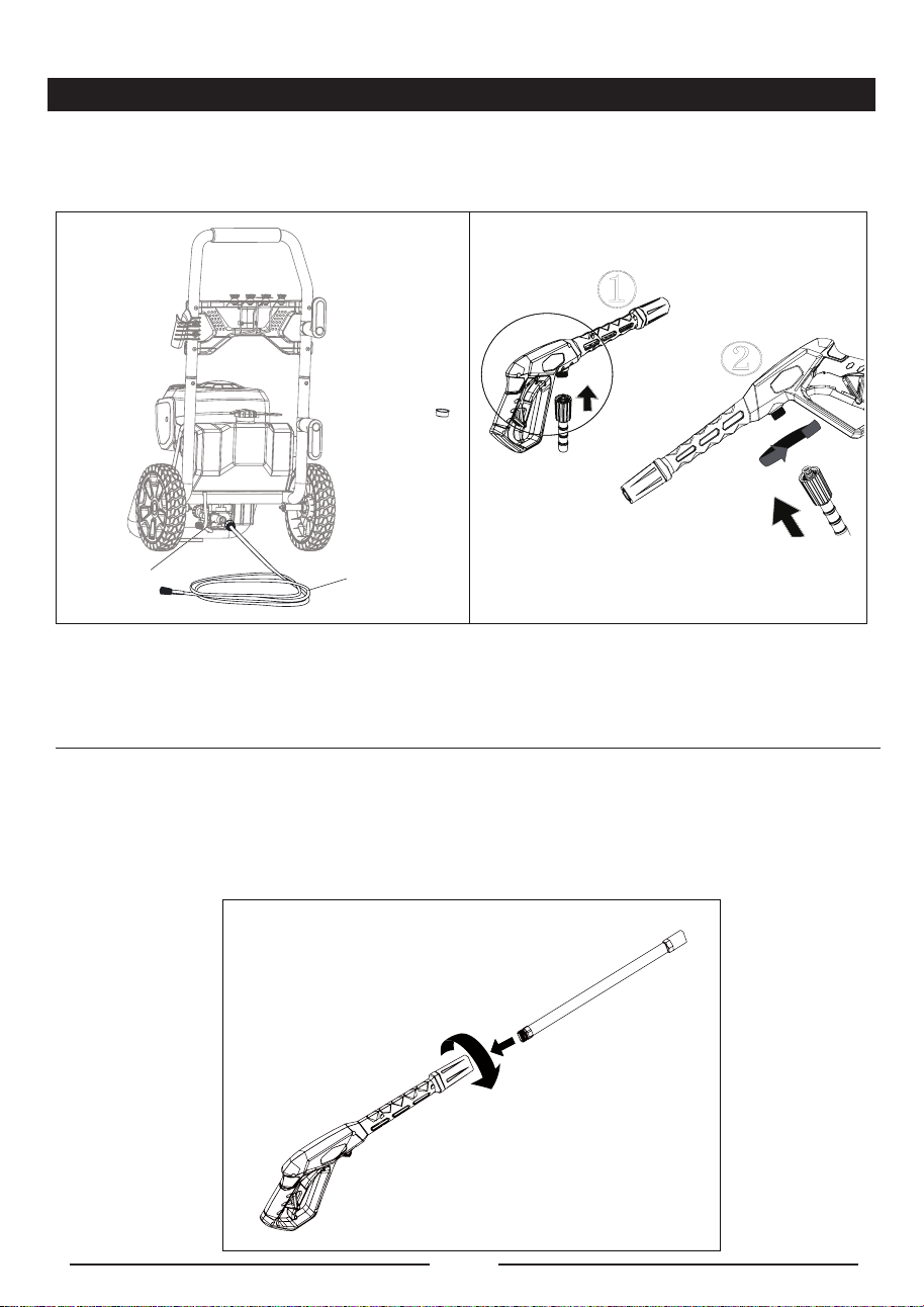
CONNECTING HIGH PRESSURE HOSE TO TRIGGER HANDLE (See Figure 6-2.)
1. Align the pressure hose with the trigger handle and push up and into position.
2. With hose pushed into position on the trigger handle, secure in place by turning the hose lock clockwise
until fully tightened.
NOTE: For easier installation of the hose to the unit or trigger it is suggested to add pressure washer or
dish detergent to the rubber seal at each end of the hose. This will allow for easier installation and a snug
fit.
ASSEMBLING THE SPRAY WAND (See Figure 7.)
■ Push the end of the spray wand into the trigger handle and rotate clockwise to secure.
■ Pull on the spray wand to be certain it is properly secured.
Fig. 7
Outlet
Connector
High Pressure
Hose
①
②
Fig. 6-1 Fig. 6-2
ASSEMBLING THE HIGH PRESSURE HOSE
■ Connect one end of the hose to the water outlet connector, while the other end to the trigger gun.
(See Figure 6.)
EN - 16
ASSEMBLY
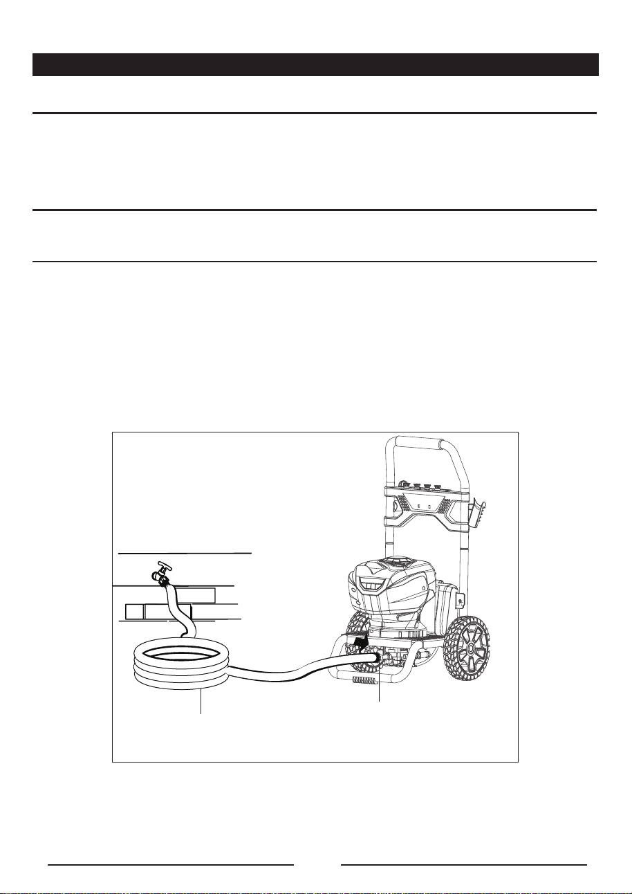
Fig. 8
A
A-Garden Hose
B-Water Inlet Connector
B
CONNECTING THE GARDEN HOSE (See Figure 8.)
C A U T I O N :
Always observe all local regulations when connecting hoses to the water main. Some areas have
restrictions against connecting directly to public drinking water supply to prevent the feedback of
chemicals into the drinking water supply. Direct connection through a receiver tank or backflow
preventer is usually permitted.
■ Uncoil the garden hose.
NOTE:There must be a minimum of 10 feet of unrestricted garden hose between the water intake and
the garden hose faucet or shut off valve (such as a “Y” shut off connector).
■ Run water through the hose for 30 seconds to clean any debris from the hose.
■ Inspect the screen in the water intake.
■ If the screen is damaged, do not use the machine until the screen has been replaced.
■ If the screen is dirty, clean it before connecting the garden hose to the machine.
■ With the hose faucet turned completely off, attach the end of the garden hose to the water intake.
Tighten by hand only.

EN - 17
OPERATION
W A R N I N G
Do not allow familiarity with the product to make you careless. Remember that a careless fraction of a
second is sufficient to inflict serious injury.
W A R N I N G
Always wear eye protection with side shields marked to comply with ANSI Z87.1. Failure to do so could
result in objects being thrown into your eyes resulting in possible serious injury.
W A R N I N G
Do not use any attachments or accessories not recommended by the manufacturer of this product. The
use of attachments or accessories not recommended can result in serious personal injury.
W A R N I N G
Never direct a water stream toward people or pets, or any electrical device. Failure to heed this warning
could result in serious injury.
APPLICATIONS
You may use this product for the purposes listed below:
■ Cleaning boats, cars, trucks, motorcycles, outdoor furniture, grills, house siding, driveways, patios
and decks.
DETERGENT ADDING AND USE (See Figure 9-1.)
Use only detergents designed for pressure washers; household detergents, acids, alkalines,
bleaches, solvents, flammable material, or industrial grade solution can damage the pump. Many
detergents may require mixing prior to use. Prepare cleaning solution as instructed on the solution
bottle.
SOAP APPLICATION
Soap is applied under low pressure high volume for optimum performance.
Soap can not be applied under high pressure with this machine
Soap / Detergent can only be applied with this machine when the "black (75 degree) soap tip" is
installed.
To add detergent:
■ Place pressure washer upright on a flat surface
EN - 18
OPERATION
■ Remove cap from detergent tank
■ Pour detergent into tank
■ Reinstall cap
C A U T I O N :
Use only approved pressure washer cleaners. Do not use bleach, chlorine,or any cleaners containing
acids.
To use:
■ Connect low pressure black soap spray tip to the wand connector. (See Figure 9-2.)
■ Squeeze the trigger and the detergent will automatically be mixed with the water and dispensed from
the spray tip.
NOTE: Use a funnel, if needed, to prevent accidental spilling of the detergent outside the tank. If
any detergent is spilled during the filling process, make sure the unit is cleaned and dried before
proceeding.
Detergent
Tank
Fig. 9-1
Use Black Soap Tip Only
Fig. 9-2
EN - 19
OPERATION
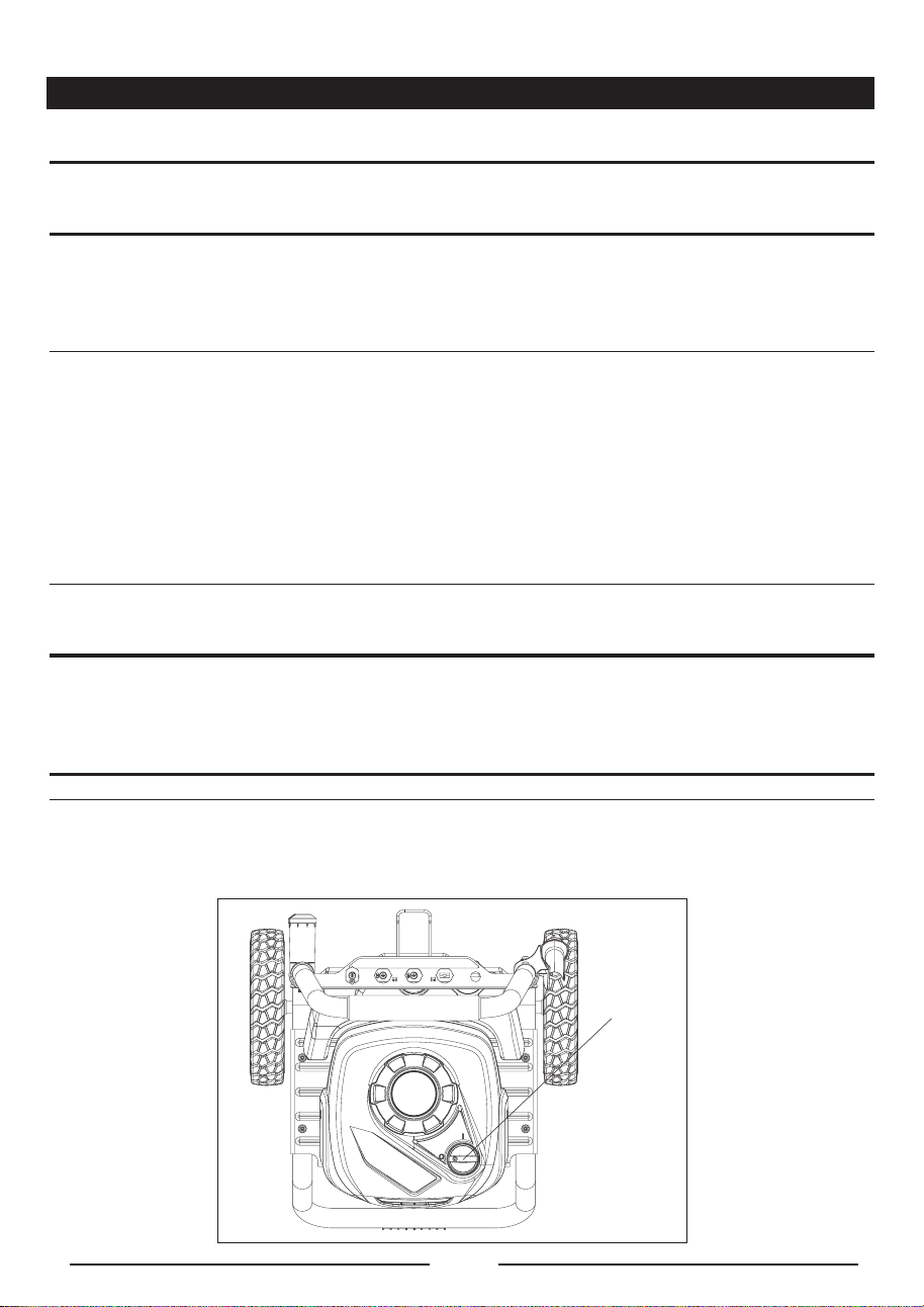
STARTING AND STOPPING THE PRESSURE WASHER (See Figure 10.)
C A U T I O N :
Do not run the pump without the water supply connected and turned on.
■ Connect the garden hose.
■ Turn the garden hose on then squeeze the trigger and run water hose with motor in OFF position
until a steady stream of water appears. This helps drain air from tank and lines.
NOTE: If the pressure washer pulsates and the water stream is intermittent turn the pressure washer off
and continue to bleed air out of the system. Ensure to check that the garden hose is fully turned on and
not kinked.
■ After ensuring the On/Off switch is in the OFF ( O ) position, connect the pressure washer to the
power supply.
■ Press the reset button on the pressure washer’s plug to make sure the unit is ready for operation.
■ Rotate to ON ( I ) position on the switch to start the motor.
■ To stop the motor, release the trigger and rotate to OFF( O ) position on the switch.
NOTE: The pressure washer may be on and the system may have pressure even when the pump and/
or motor cannot be heard running. Always use caution around the pressure washer.
C A U T I O N :
Hold the trigger handle securely with both hands. Expect the trigger handle to move when the trigger
is pulled due to reaction forces. Failure to do so could cause loss of control and injury to yourself and
others.
NOTE: AUTO ON/OFF SWITCH: This pressure washer is equipped with an Auto Start/Stop feature. To
operate: Turn the power switch to the On (I) position. Pump will pressurize and shut down immediately.
Once the trigger of the gun is depressed the unit will turn on. Unit will shut off and be in standby mode
when trigger is released.
Fig. 10
On(I) /Off(0)
Switch
EN - 20
OPERATION
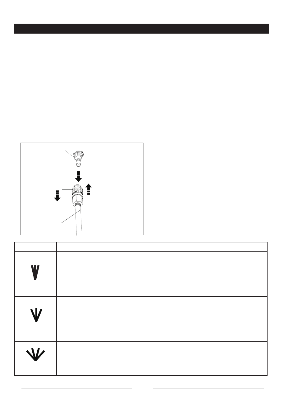
USING THE SPRAY TIPS (See Figure 11.)
Each of the spray tips has a different spray pattern. Before starting any cleaning job, determine the best
spray tip for the job. The following chart offers some general guidelines to help you choose the best
spray tip for your application.
NOTE: Always try spray tip in an inconspicuous area rst.
■ Turn off the pressure washer and shut off the water supply. Pull trigger to release water pressure.
■ Engage the lock-out on the trigger handle by pushing the trigger lock button to the right.
■ Pull out the desired spray tip from the tip storage on the handle.
■ Pull back the quick-connect collar on the spray wand.
■ Push the spray tip into place in the spray wand.
■ Push the collar forward so that the spray tip is secured properly. Check to see that the spray tip is
secure.
SPRAY TIP APPLICATION
Yellow - Narrow fan tip (15° )
■ The yellow pressure washer tip provides high versatility with its 15 degree angle
tip. Referred to as the washing tip, because it provides adequate pressure to
remove dirt from surfaces, but is designed to not damage many surfaces. This
pressure washer tip is designed for “sweeping” foliage or debris given its wide
angle. This tip is versatile due to its wide area of cleaning and strong pressure
application.
25
O
Green - Narrow fan tip (25° )
■ The green pressure washer tip provides high versatility with its 25 degree angle
tip. Referred to as the washing tip, because it provides adequate pressure to
remove dirt from surfaces, but is designed to not damage many surfaces. This
pressure washer tip is designed for “sweeping” foliage or debris given its wide
angle. This tip is versatile due to its wide area of cleaning and strong pressure
application.
40
O
White - Wide fan tip (40° )
■ The white 40 degree tip, referred to as the “fan” tip creates the widest area of
cleaning with relatively low pressure. This pressure washer tip is best used for
light or delicate cleaning applications. It is recommended for light cleaning on
wood decks and other soft or delicate surfaces.
1-Pull back the quick-connect collar
2-Push the spray tip into place
3-Push the collar forward
Fig. 11
1
2
3
Spray Tip
Spray Wand
15
O
EN - 21
OPERATION
Slot
Fig. 12
Trigger
Lock out
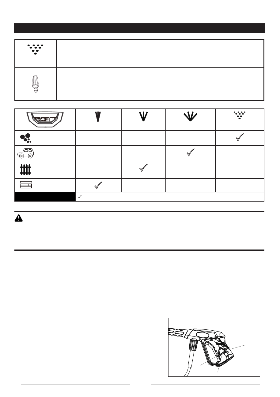
SOAP
Black - Soap spray tip
■ The black soap spray tip, is used for soap application. Soap is applied under low
pressure high volume for optimum performance. Soap cannot be applied under
high pressure with this machine.
Turbo Nozzle Tip
■ The nozzle rotates in a zero to 15 degree spray pattern in a circular motion to
break down tough dirt and grime. The spray pattern can cover area of 4 to 8
inches wide, depending on a distance between the tip and the surface being
cleaned.
15
O
25
O
40
O
SOAP
CAR
WOOD
CONCRETE
Recommended Nozzle
W A R N I N G
NEVER change spray tips without engaging the lock-out on the trigger handle and NEVER point the
wand at your face or at others. The quick-connect feature contains small springs that could eject the
spray tip with some force. Failure to heed this may cause personal injury.
TO DISCONNECT A SPRAY TIP FROM THE SPRAY WAND ONCE THE CLEANING JOB
IS COMPLETE:
■ Turn off the pressure washer and shut off the water supply. Pull trigger to release water pressure.
■ Remove the spray tip by placing hand over spray then pulling back the quick-connect collar. Place
spray tip in the tip storage area on the units folding handle.
USING THE SPRAY WAND TRIGGER (See Figure 12.)
For greater control and safety, keep both hands on the trigger handle at all times.
■ Pull back and hold the trigger to operate the pressure washer.
■ Release the trigger to stop the flow of water through the tip.
TO ENGAGE THE LOCK-OUT:
■ Push up on the lock-out until it clicks into the slot.
TO DISENGAGE THE LOCK-OUT:
■ Push the lock-out down and into its original position.
EN - 22
MAINTENANCE
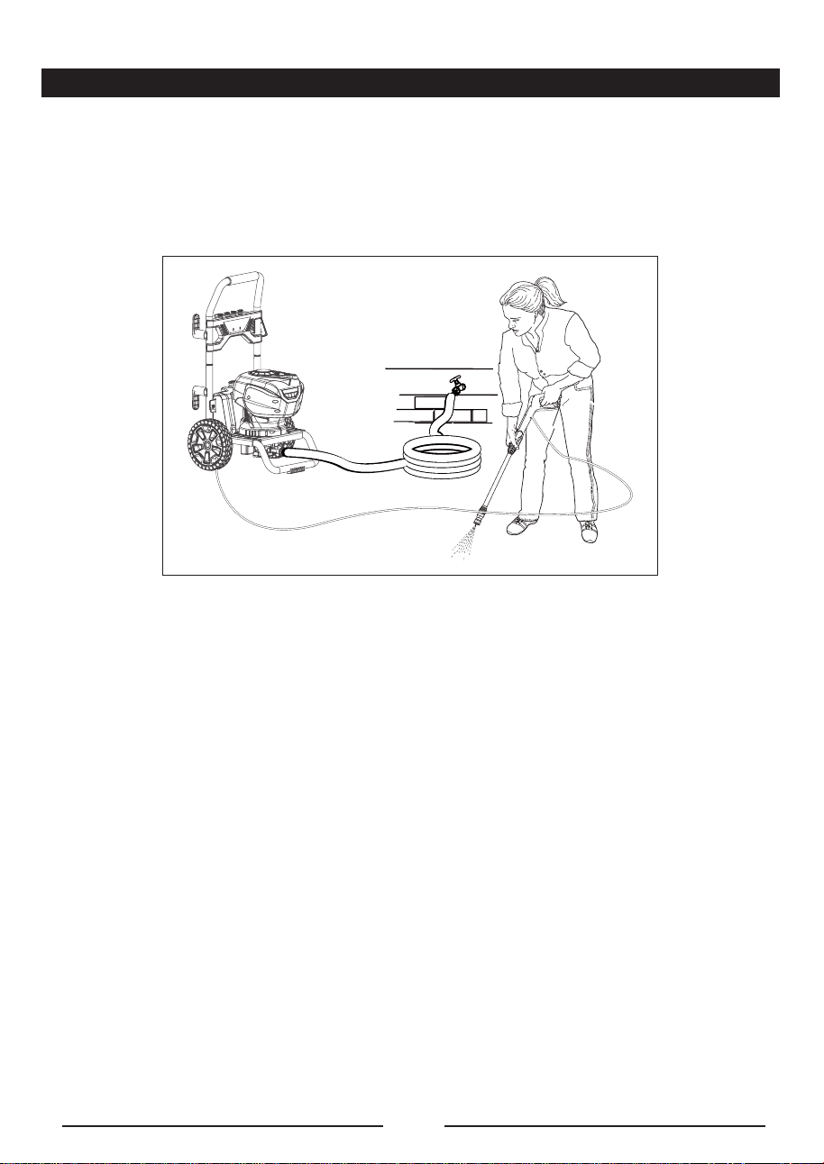
OPERATING THE PRESSURE WASHER (See Figure 13.)
Use only detergents designed for pressure washers. Many detergents may requrie mixing prior to use.
Prepare cleaning solution as instructed on the solution bottle.
To clean:
■ Pour detergent in the detergent tank.
■ Install the black soap tip on the spray wand.
■ Start the pressure washer and spray the detergent on a dry surface using long, even, overlapping
strokes. To prevent streaking, do not allow detergent to dry on the surface.
To rinse:
■ Using the 25° spray tip, spray away from the rinsing surface for approximate 10 seconds to allow
any remaining detergent to be flushed from the line.
■ Start at the top of the area to be rinsed and work down, overlapping the strokes.
For the most effective cleaning, the spray tip should be between 8 in. and 24 in. from the surface to be
cleaned. If the spray is too close it can damage the cleaning surface.
Fig. 13
EN - 23
MAINTENANCE
W A R N I N G
When servicing, use only identical replacement parts. Use of any other parts may create a hazard or
cause product damage.
W A R N I N G
Before inspecting, cleaning or servicing the machine, turn off the unit, unplug from the outlet, pull trigger
to release water pressure and disconnect the high pressure hose. Failure to follow these instructions
can result in serious personal injury or property damage.
GENERAL MAINTENANCE
Avoid using solvents when cleaning plastic parts. Most plastics are susceptible to damage from various
types of commercial solvents and may be damaged by their use. Use clean cloths to remove dirt, dust,
oil, grease, etc.
W A R N I N G
Do not at any time let brake fluids, gasoline, petroleum based products, penetrating oils, etc.,come
in contact with plastic parts. Chemicals can damage, weaken or destroy plastic which may result in
serious personal injury.
Only the parts shown on the parts list are intended to be repaired or replaced by the customer.
All other parts should be replaced at an authorized service center.
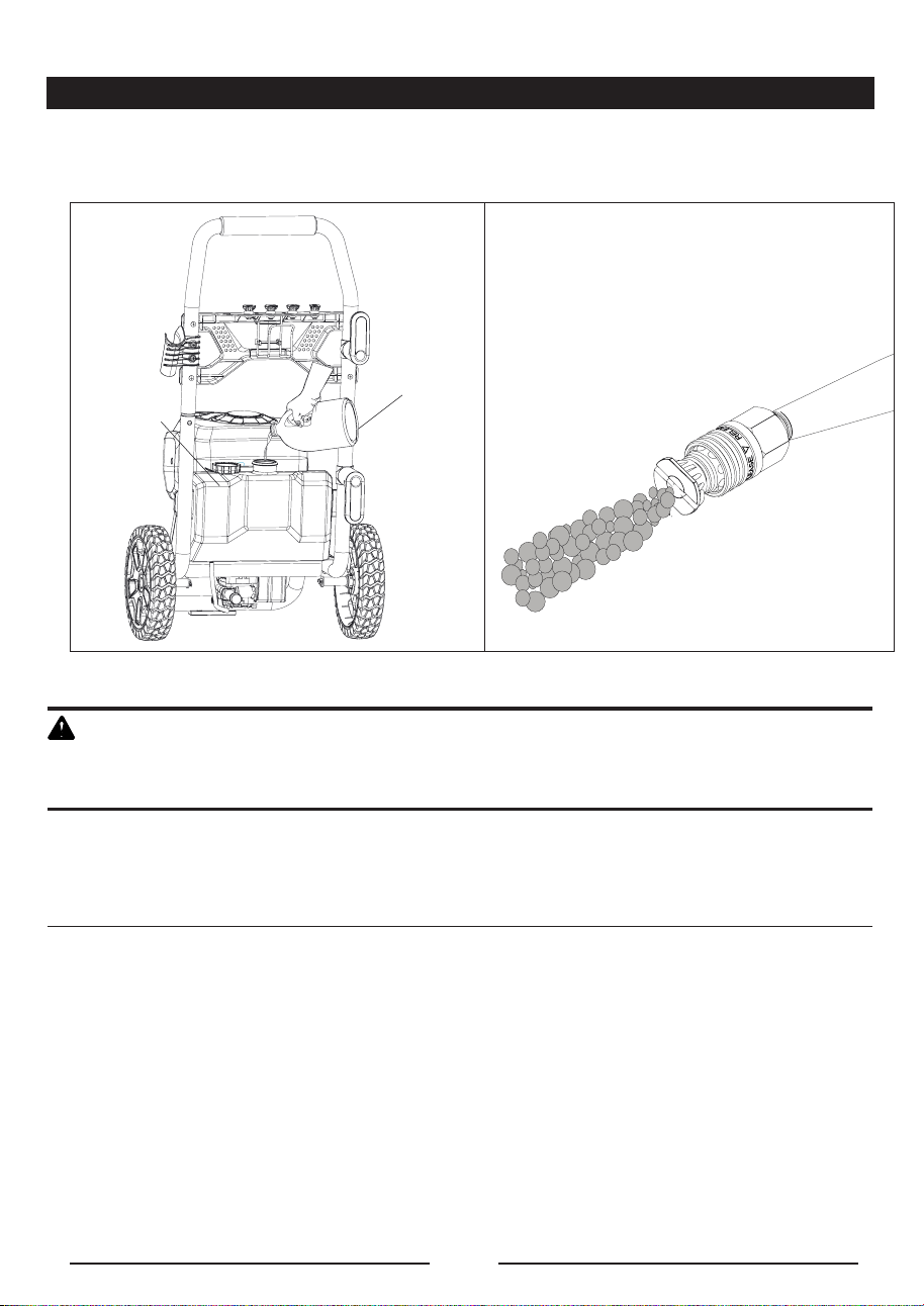
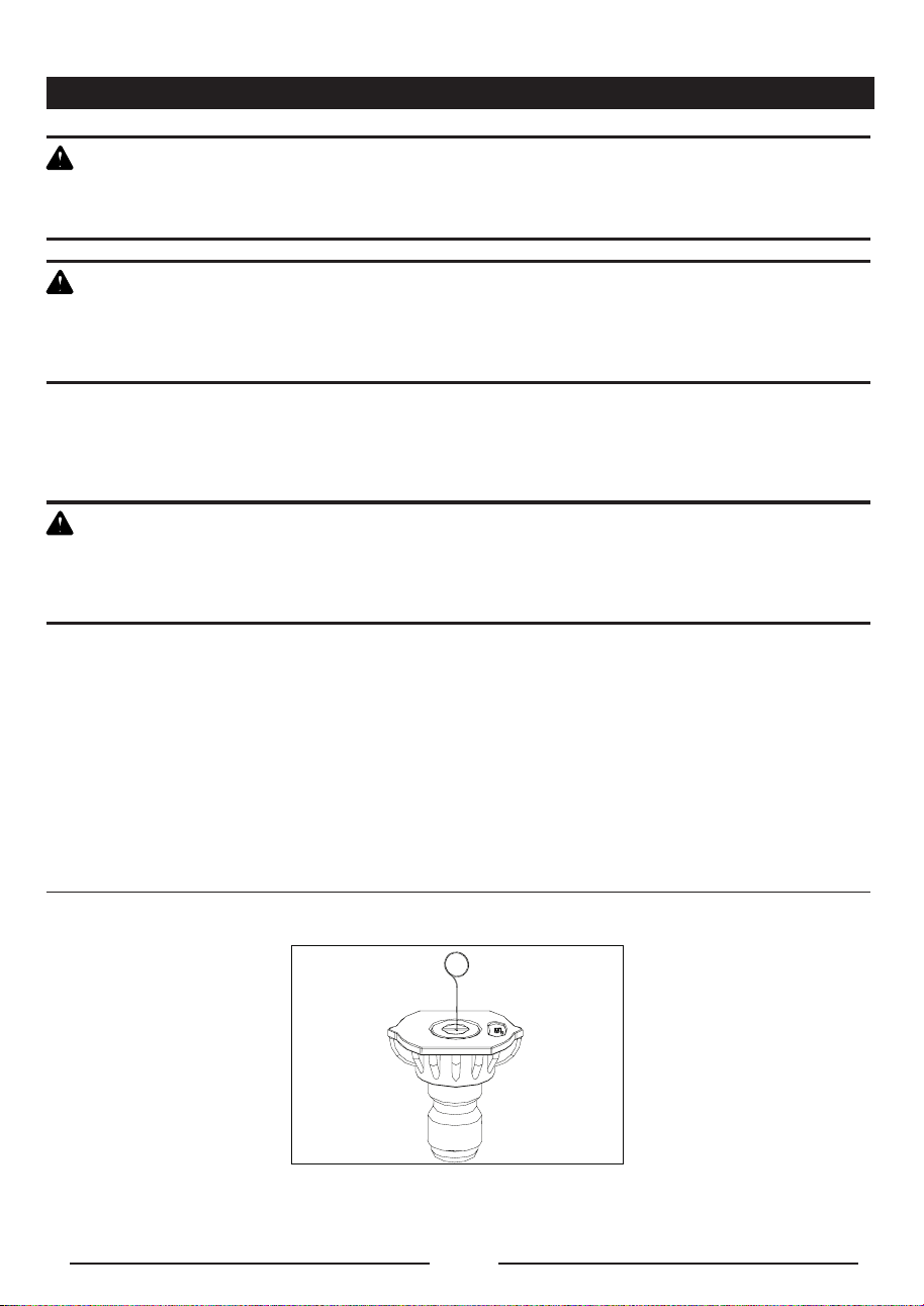
SPRAY TIP MAINTENANCE (See Figure 14.)
Excessive pump pressure (a pulsing sensation felt while squeezing the trigger) may be the result of a
clogged or dirty spray tip.
■ Unplug the pressure washer.
■ Turn off the pressure washer and shut off the water supply. Pull trigger to release water pressure.
■ Remove the spray tip from the spray wand.
NOTE: Never point the spray wand at your face.
Fig. 14

EN - 24
MAINTENANCE
Using the spray tip cleaning tool provided, free any foreign materials clogging or restricting the spray tip
opening. Refer to Fig. 14
■ Using a garden hose, flush debris out of the spray tip by back flushing (running the water through the
spray tip backwards or from the outside to the inside).
■ Reconnect the spray tip to the spray wand.
■ Turn on the water supply.
QUICK WINTERIZING PROCEDURE
If you cannot do the Optimum Winterizing procedure, you can still protect your pressure washer from
winter damage by doing below:
■ Disconnect all water connections.
■ Turn on the machine for a few seconds, until the remaining water in the pump exits. Turn off
immediately.
■ Do not allow high-pressure hose to become kinked.
■ Store the machine and accessories in a room that does not reach freezing temperatures. Do not
store near furnace or other sources of heat as it may dry out the pump seals.
C A U T I O N :
Drain gun assembly of any remaining water. Aim gun downwards and squeeze trigger.
SHUTTING DOWN AND CLEANING UP
■ (If you are not using detergent, go directly to Step 2.) When you have finished using the detergent
injection system, fill detergent bottle with clean water. Siphon water at low-pressure for one minute
so that all detergent is flushed through system.
■ Disconnect the garden hose from the water inlet on the unit.
■ Press trigger to release any remaining water pressure.
■ Turn the switch to "OFF" (0) position.
■ Unplug the power cord from the outlet.
■ Engage gun safety lock.
TAKING A BREAK
■ Engage gun safety lock.
■ Turn unit to “OFF” (O) position.
■ Unplug the power cord from the outlet.
I M P O R T A N T :
The use of a pump protector is recommended when storing to help prevent a against freezing over the
winter months. It also help prevent the seals from drying out while sitting in storage in all climates.

EN - 25
TROUBLESHOOTING
PROBLEM POSSIBLE CAUSE SOLUTION
Motor will not start.
On/Off switch is in the
“OFF” (O) position.
Turn switch to the “ON” ( | ) position.
Power cord is not
plugged in.
Plug in power cord.
Electrical outlet does
not supply adequate
power.
Try a different outlet.
Tripped pressure
washer circuit breaker
Allow to cool, and restart unit.
Power switch is ON
however gun trigger is
not squeezed ON.
With power switch ON push in on the gun
trigger which will engage the AUTO ON switch.
PCB board is defective.
Disconnect the power cord from the outlet and
plug the machine again 5 minutes later.
Unit does not reach
high pressure.
Diameter of garden
hose is too small.
Replace with a 1” (25 mm) or 5/8” (16 mm)
garden hose.
Water supply is
restricted.
Check garden hose for kinks, leaks and
blockage.
Not enough water
supply.
Open water source fully.
Pressure Tip has not
been installed on wand
assembly.
Add desired pressure tip to end of wand. See
page 20 Fig. 11 for details.
Water inlet filter is
clogged.
Remove lter and rinse in warm water.
Output pressure varies
high and low.
Not enough inlet water
supply.
Turn water on fully. Check garden hose for
kinks, leaks or blockage.
Pump is sucking air.
Check that hoses and ttings are airtight, Turn
"OFF" machine, and purge pump by squeezing
trigger gun until a steady ow of water emerge
through the spray tip.
Water inlet filter
clogged.
Remove lter and rinse in warm water.
Supply voltage below
minimum.
Verify that only the pressure washer is running
on this circuit.
Calcied gun, hose or
power spray tip.
Run distilled vinegar through detergent tank.

EN - 26
TROUBLESHOOTING
PROBLEM POSSIBLE CAUSE SOLUTION
Detergent is not coming
out.
Detergent is too thick. Dilute detergent.
Filter on detergent
suction tube is
clogged.
Run warm water through lter to remove build-
up.
Damaged or clogged
detergent suction
tube.
Remove obstruction or replace detergent
suction tube.
Spray tip is
obstructed.
Blow out or remove debris with a fine needle.
Garden hose connection
leaks.
Loose connection. Tighten connection.
Missing/worn rubber
washer.
Insert new washer.
Spray wand, extension, or
spray tip leaks.
Broken o-ring or
plastic insert.
Call the Toll-Free Helpline.
Pump is noisy.
Pump is sucking air.
Check that hoses and ttings are airtight. Turn
off machine and purge pump by squeezing
trigger gun until a steady ow of water emerges
through the spray tip.
Water filter is clogged. Remove water lter and rinse in warm water.
Water leaks from pump.
Loose fittings. Check that all ttings are tight.
Water seals are
damaged or worn.
Call the Toll-Free Helpline.
Oil is dripping.
Oil seals are damaged
or worn.
Call the Toll-Free Helpline.
Soap does not come
out or comes out at low
pressure.
75 degree tip / Soap
Tip (Black color) is not
installed in wand.
Install 75 degree, black, soap tip in wand.
Soap tank may be
plugged with debris or
thick soap.
Empty soap from tank, clean out using vinegar
and water.

EN - 27
TROUBLESHOOTING
PROBLEM POSSIBLE CAUSE SOLUTION
Motor buzzes but fails to
run.
Supply voltage below
minimum.
Verify that only the pressure washer is running
on this circuit.
System has residual
pressure.
Turn unit “OFF”, squeeze trigger on spray
wand to release pressure, then turn unit "ON".
Voltage loss due to
extension cord.
Unplug any extension cords attached and plug
the unit directly into the outlet.
Pressure washer not
used for long periods.
Call the Toll-Free Helpline.
Residual friction
among components.
Unit might hum.
Disconnect water supply and power ON for 2
to 3 seconds, repeat couple times or until the
motor starts.
No water.
Water supply is OFF. Turn ON water supply.
Kink in the garden
hose.
Remove kink in garden hose.
NOTE: AUTO ON/OFF SWITCH: This Pressure washer is equipped with an Auto Start/
Stop feature. To operate: Press power switch On (I). Pump will pressurize and shut
down immediately. Once the trigger of the gun is depressed the unit will turn on. Unit
will shut off and be in standby mode when trigger is released.

EN - 28
WARRANTY
GREENWORKS™ hereby warranties this product, to the original purchaser with proof of purchase, for a
period of one (1) years against defects in materials, parts or workmanship. GREENWORKS™, at its own
discretion will repair or replace any and all parts found to be defective, through normal use, free of charge
to the customer. This warranty is valid only for units which have been used for personal use that have not
been hired or rented for industrial/ commercial use, and that have been maintained in accordance with
the instructions in the owners’ manual supplied with the product from new.
ITEMS NOT COVERED BY WARRANTY:
1. Any part that has become inoperative due to misuse, commercial use, abuse, neglect, accident,
improper maintenance, or alteration; or
2. The unit, if it has not been operated and/or maintained in accordance with the owner'smanual; or
3. Normal wear, except as noted below;
4. Routine maintenance items such as draining the water to avoid freezing/ice damage to
pump and components.
5. Normal deterioration of the exterior nish due to use or exposure.
GREENWORKS HELPLINE (1-855-345-3934):
Warranty service is available by calling our toll-free helpline, at 1-855-345-3934.
Order Replacement parts online @
www.greenworkstools.com.
TRANSPORTATION CHARGES:
Transportation charges for the movement of any power equipment unit or attachment are the responsibility
of the purchaser. It is the purchaser’s responsibility to pay transportation charges for any part submitted
for replacement under this warranty unless such return is requested in writing by GREENWORKS.
EN - 29
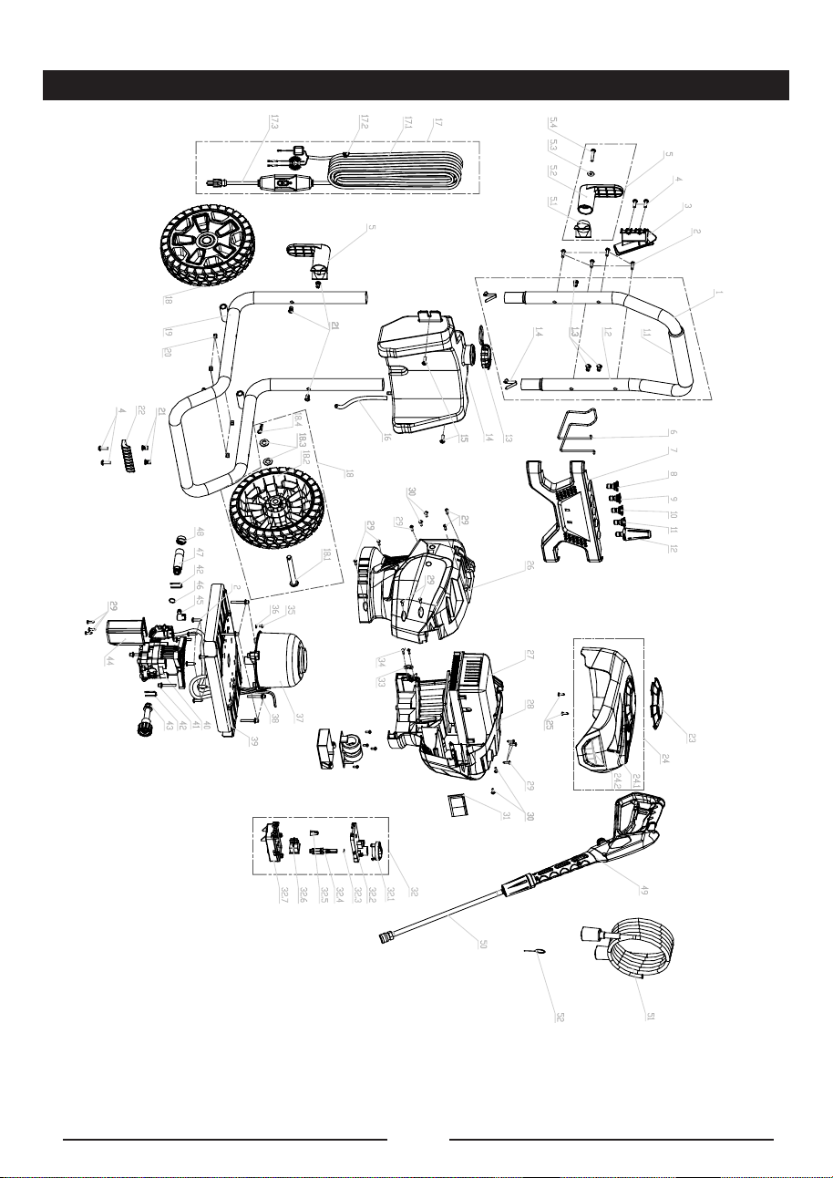
EXPLODED VIEW

EN - 30
PARTS LIST
ITEM NO. PART NO. DESCRIPTION QTY
1 311201936 Upper handle assy 1
1.1 349011936 Foam 1
1.2 331031936 Upper handle 1
1.3 322021822 Screw 3
1.4 33306847 Spring bnutton 2
2 322011628 Screw 10
3 341101936 Gun holder 1
4 322011635 Screw 8
5 311211936 Cord retainer 2
5.1 341071833 Connector 1
5.2 341101635 Cord retainer 1
5.3 32913847 Washer 1
5.4 322021635 Screw 1
6 333011936 Hose holder 1
7 341001936 Front panel assy 1
8 312151923 15°spray tip 1
9 312251923 25°spray tip 1
10 312401923 40°spray tip 1
11 34139319 Soap tip 1
12 31208363 Turbo nozzle 1
13 342011635 Soap tank cap 1
14 341031936 Soap tank 1
15 341141823 Screw 2
16 34900365 Pressure hose 1
17 311231936 Power cord assy 1
17.1 364991936 Power cord assy 1
17.2 34146363 Cord clip 1
17.3 364031936 Anticreeping protector 1
18 311301936 Wheel assy 2
18.1 332201936 Axle 1
18.2 341271936 Wheel assy 1
18.3 32908301A Washer 2
18.4 32229301A Ring 1
19 331041936 Lower bracket 1

EN - 31
PARTS LIST
20 32222301A Nut 4
21 322021822 Screw 5
22 341201936 Bracket support 1
23 341041936 Decorative cover 1
24 311311936 Decorative cover assy 1
24.1 341071936 Decorative cover 1
24.2 341151936 Transparent indicator panel 1
25 32208302A Screw 2
26 341081936 Left housing 1
27 331011836 AC brushless activator 1
28 341091936 Left housing 1
29 322031635 Screw 15
30 322011936 Screw 4
31 311501936 PCB LED indicator 1
32 311221936 Switch box assy 1
32.1 341111936 Switch knob 1
32.2 341121936 Switch box cover 1
32.3 34216301A O-ring 1
32.4 341141936 Switch lever 1
32.5 36511154 Terminal cap 1
32.6 363021628 Power switch 1
32.7 341131936 Switch box 1
33 34120319 Press board 1
34 3320303 Screw 2
35 32204301A Screw 1
36 32912301A Washer 1
37 361011936 AC Motor
38 332081936 Screw 4
39 331051936 Iron plate 1
40 311281936 Pumo assy 1
41 332081936 Screw 4
42 33302365 U pin 2
43 311241936 Water inlet connector 1
1

EN - 32
PARTS LIST
TOLL-FREE HELPLINE: 1-855-345-3934
Rev: 00 (12-11-16)
44 341181936 Switch box cover 1
45 341071923 Hose connector 1
46 34202368 O-ring 1
47 332031936 Water outlt connector 1
48 34125304 Dust cap 1
49 31140363-1 GW gun assy 1
50 31145363 GW gun wand assy 1
51 311311635 High pressure hose 1
52 33201671 Tip cleaner 1