Page 1
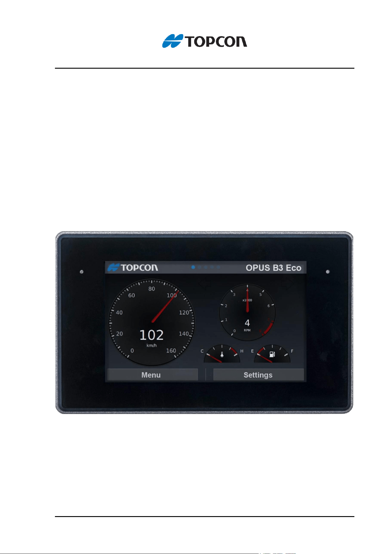
OPUS B3 ECO
Operating Manual
Hardware Description

Page 2
Versions
Example
OPUSB3EN1CANB000
OPUSB3 model
E E=ECO; S= Standard
N N= Neutral
1 1. Generation
CAN CAN=Projektor/C++
CDS=CODESYS
ISO=ISO-UT
B B=Basic, F= Full, A=Automotive Ethernet, T = Basic Touch
000 customer specific identification
All product names cited in this operating manual are trademarks or registered
trademarks of the respective companies.
Operating Manual OPUS B3 ECO
Order number: OPUSBA00B3
Topcon Electronics GmbH
Industriestraße 7, 65366 Geisenheim
+49 6722 / 6722 4026 - 888
Supplements or a special operator manual may be required for customer-
specific devices.
Version 4, November 2024
All rights reserved, including translation.
No part of this operating manual may be reproduced, in any form, (print,
photocopy, microfilm, or a different process), nor may it be processed,
duplicated, or distributed using electronic systems, without written permission
from Topcon Electronics GmbH, Geisenheim.
All content is subject to change without notice. All previous versions are
rendered obsolete with publication of this manual.
All information contained herein is subject to correction, manufacturer is not
liable for any errors in this material.
Errors and technical changes excepted.

Table of contents
Page 3
Table of contents
1 Preliminary Notes ............................................................................................... 5
1.1 Used Instruction Types ........................................................................................................5
2 Safety instructions, guarantee and liability ..................................................... 6
2.1 Common .................................................................................................................................6
2.2 Qualified Personnel ..............................................................................................................6
2.3 Power Supply ........................................................................................................................7
2.4 Interventions in the device ...................................................................................................7
2.5 Safety Instructions for the OPUS B3...................................................................................8
3 Intended Use ..................................................................................................... 11
3.1 Example of Use .................................................................................................................. 12
3.2 Device Description ............................................................................................................. 13
3.2.1 OPUS B3 ECO ................................................................................................................ 13
3.3 Features Overview for OPUS B3 ...................................................................................... 16
3.4 Application Development .................................................................................................. 16
3.5 Development Kit ................................................................................................................. 18
4 Getting Started ................................................................................................. 20
4.1 Check the delivered parts ................................................................................................. 20
4.2 Mounting ............................................................................................................................. 20
4.2.1 Standalone Mounting Instruction for OPUS B3 .......................................................... 22
4.2.2 Dashboard Mounting Instruction for OPUS B3 .......................................................... 23
4.2.3 Connector Cover for OPUS B3 ECO ............................................................................ 24
4.2.4 Dashboard Cut-out ........................................................................................................ 25
4.2.5 Mounting Cover for OPUS B3 ECO .............................................................................. 26
4.2.6 Screen Protection Foil for OPUS B3 ECO ................................................................... 27
5 Electrical installation OPUS B3 ....................................................................... 28
5.1 Unused plugs ..................................................................................................................... 30
5.2 Power Supply ..................................................................................................................... 30

Page 4
5.3 First steps ........................................................................................................................... 30
5.4 Cleaning/ service / maintenance ...................................................................................... 31
6 Technical Documentation ................................................................................ 32
6.1 Dimension Drawings - OPUS B3 Eco ............................................................................... 33
6.2 Specification ....................................................................................................................... 34
6.3 Declaration of Conformity ................................................................................................. 35
6.3.1 Declaration of Conformity for OPUS B3 ECO Basic and Touch ............................... 35
6.3.2 Declaration of Conformity for OPUS B3 ECO Full ..................................................... 36
Safety instructions, guarantee and liability
Page 5
1 Preliminary Notes
This document is valid for the following OPUS B3 ECO version:
• OPUSB3E - “ECO”
This document is directed to the qualified personnel and contains all the important
information to the correct use of the OPUS B3.
Please read this document before the first use and keep it during the operation.
To provide a better overview, this operating manual cannot present all details for
handling the OPUS B3 in all conceivable application cases. Neither can all conceivable
methods of setting up the device, operating the device, and servicing the device be
discussed in this manual. In case more information or support is required please
contact manufacturer technical support department.
1.1 Used Instruction Types
This operating manual contains instructions that must be complied with for your
personal safety and to avoid damage to property.
The instructions are presented as follows listed by degree of hazard:
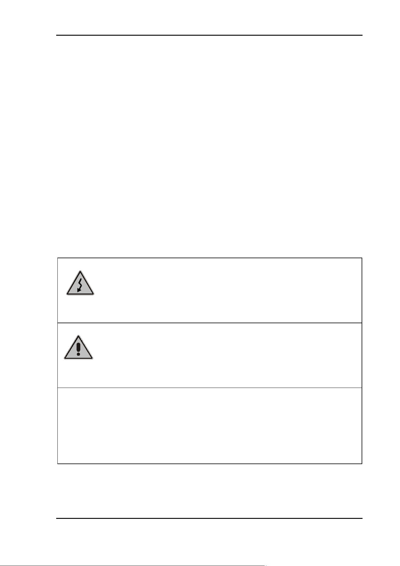
Hazard!
Very Important information
Malfunction or Failure possible if non-compliance
Caution!
Severe bodily injury or property damage can occur if the
respective precautionary measures are not taken
Note
Additional information about the product, the handling of the
product or the respective part of the operating manual to which
particular attention should be paid.

Safety instructions, guarantee and liability
Page 6
2 Safety instructions, guarantee and liability
2.1 Common
Read this operating manual before commissioning the OPUS B3. Keep this operating
manual where it is accessible to all users at any time. Every person who is assigned
to commission or operate the OPUS B3 must have read and understood the operating
manual and the safety instructions in particular!
This operating manual contains instructions that must be complied with for your
personal safety and to avoid damage to property. Failure to follow these safety
instructions could result in fire, electric shock, or other injury or damage to OPUS B3
or other property.
2.2 Qualified Personnel
This operating manual is intended for technically qualified personnel, who have the
appropriate skills in measurement, control, and regulating technology.
Precise knowledge of all safety instructions and warnings contained in this operating
manual, as well as problem-free technical implementation of these instructions and
warnings are the prerequisites for hazard-free installation, commissioning, safe
operation, and maintenance, of the operator panel. Consequently, it is strictly required
that all measures be performed by qualified personnel.
Qualified personnel, in accordance with the safety and warning instructions contained
in this operating manual are personnel, who
• are familiar with CAN bus systems, related protocols and network designs that
fulfill all legal requirements of the intended application, so that they are able to
program the OPUS operator panel accordingly
• have gained knowledge of the programming related concepts by education or
trainings. Using the Projektor Tool a Projektor Tool training by Topcon needs to
be attended. Using CODESYS a CODESYS training needs to be attended,
either held by Topcon or 3S.
• are familiar with the safety concepts of automation technology, either as project
design personnel
• or operating personnel who have been instructed in how to handle the
automation technology, and who are familiar with the section of this manual
which deals with operation.
• or who, as commissioning, and service personnel have been trained to repair
this type of automation technology, or who are authorized to commission,
ground, and label electrical circuits and devices, or systems, in accordance with
technical safety standards.
All persons who are involved in project planning, installation and operating the OPUS
B3 must be familiar with automation technology safety concepts, and they must be
qualified in accordance with the guidelines listed above.
Safety instructions, guarantee and liability
Page 7
Serious bodily injury and property damage can occur in the event of unqualified
interventions in the device, or the system, or failure to heed the warning instructions
specified in this operating manual.
Consequently, only personnel who are appropriately qualified may undertake
interventions on this device, or on the associated system.
2.3 Power Supply
OPUS B3 is designed for 12 V and for 24 Volt battery systems. The operating voltage
range is 8-36 VDC, overvoltage resistance 48V for 5 minutes, inverse-polarity
protection up to -48 VDC for 5 minutes.
2.4 Interventions in the device
The OPUS B3 has been developed, manufactured, and tested in compliance with
applicable standards. When the handling guidelines and safety-related instructions
described here are complied with for project design, mounting, intended use, and
maintenance, normally the product poses no hazards relative to property damage or
to personal health. Nevertheless, the device can cause residual hazards if it is used or
operated improperly by personnel who have not been trained.
In case of malfunctions or lacks please get in contact with the manufacturer. Any
interventions in the device can cause serious interferences of the security for people
and machines. They are not allowed and lead to disclaimer of liability and guarantee
exclusion.
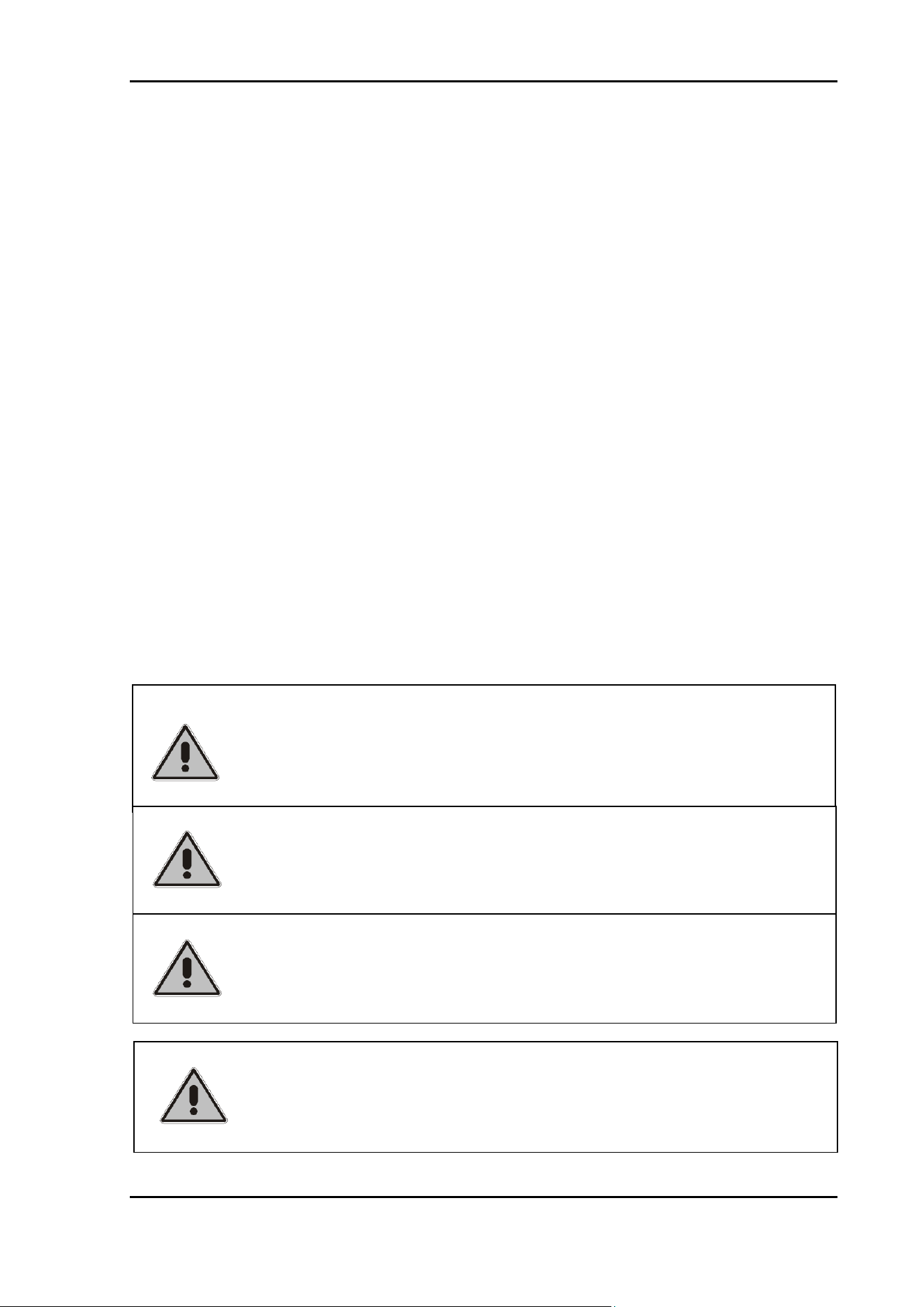
TOPCON is not liable for damage that occurs due to improper
misuse of the delivered components, or through failure to heed
the instructions in the operating manual, including the safety
instructions.
TOPCON is not liable for damage that occurs due to unintended
or intended changes of the TOPCON board support package or
any other parts of the operating system.
TOPCON is not liable for damage that occurs due to
improper programming and/or testing of the created
application that runs on the OPUS operator panels.
TOPCON is not liable for damage or malfunctions occurs using
pirated or illegal software on the OPUS operator panel.
Safety instructions, guarantee and liability
Page 8
Moreover, we expressly declare that all obligations on the part of Topcon are
exclusively derived from the respective purchase contract, in which the guarantee is
conclusively stipulated.
2.5 Safety Instructions for the OPUS B3
Dangerous high voltage
Never attempt to repair or modify OPUS B3 yourself.
Disassembling OPUS B3 may cause damage that is not covered
under the warranty and cause hazardous conditions by the high-
voltage components inside of the unit.
OPUS B3 does not contain any user-serviceable parts. Service
should only be provided by a Topcon Electronics GmbH.
Hazardous situations due to device failure
Do not use the OPUS B3 as the sole means of preventing
hazardous conditions on vehicles, machines and equipment.
Vehicles, machines and equipment must be constructed in such
a manner that defective conditions associated with the OPUS B3
cannot cause a hazardous situation for operating personnel.
Ensure that incorrect inputs via the OPUS B3, its malfunction, or
its failure cannot lead to major property damage, or to a hazard
for operating personnel.
Missing safety devices if used improperly
Precautions for the safety of a system should not be rendered
inoperable through the use of the OPUS B3.
Emergency-Stop devices must remain effective in all operating
modes.
TOPCON is not liable for injuries to third party licenses for the
contents used on OPUS panel by the end customer.
Image retention (burn-in) on LCD displays is technically
unavoidable. The customer must ensure that static images are
avoided for extended periods of time (especially at higher
ambient temperatures). This requires the use of a screensaver or
other technical solution.

Safety instructions, guarantee and liability
Page 9
Unintentional operation
Operating states can be called due to unintentional operation of
the OPUS B3 that are not appropriate for the situation.
OPUS B3 devices should be installed in such a manner that the
possibility of unintentional operation is adequately excluded.
Safety instructions, guarantee and liability
Page 10
If a further usage of the OPUS B3 will cause danger, the device
and if necessary the system needs to be switched off and be
secured against unintented activation. This particularly applies:
• If the device shows visible signs of damage
• If the device is no longer functional
• If parts of the device are disconnected or loose
• if the connection lines show visible damage
Undefined operating states
Undefined operating states can cause personal injury or property
damage.
To prevent supply line and signal line interruptions from causing
undefined or hazardous operating conditions, appropriate
hardware and software safety precautions must be maintained.
Supply lines and signal lines must be installed in such a manner
that noise (such as inductive or capacitive interference) cannot
impair OPUS B3 function.
Using Connectors and Ports:
Never force a connector into a port. Check for mechanical
obstructions on the port. If the connector and port don’t join with
reasonable ease, they probably do not match. Make sure that the
connector matches the port and that you have positioned the
connector correctly in relation to the port.
Technical Documentation
Seite 11 von 31
3 Intended Use
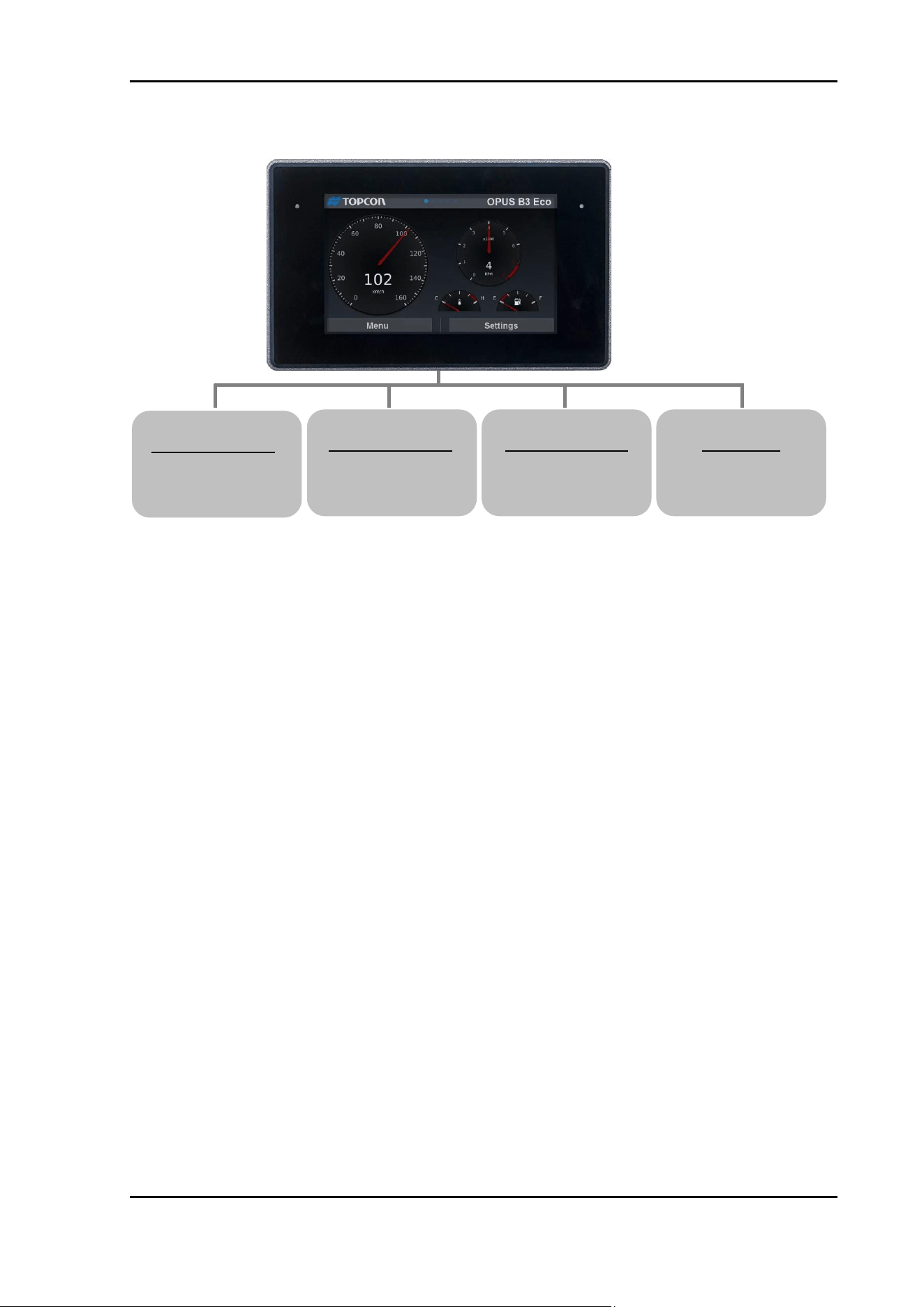
The operator panel OPUS B3 is a programmable graphical display used to operate
and monitor vehicles and working machines.
The communication with other system components, as for example decentralised I/O
module, occurs over the CAN interfaces with the supported protocols: CANopen,
J1939 and CANFreestyle (layer II).
For service purposes additional interfaces like RS232 and USB are available. Together
with Embedded Linux operating system they form a universal platform for the
communication with other CAN devices, networks or PCs.
The operator panel OPUS B3 is not admitted for security-relevant
duties for personal protection purposes.
Vehicles, machines, and equipment surrounding the OPUS B3
must be combined in such a manner that the OPUS B3 will be
warmed up equally from all sides.
Increased warming of the OPUS from the back side may cause
temporary fogging of the front glass or touch screen.
Technical Documentation
Page 12
3.1 Example of Use
Control Unit 1
Controlling of the
actuation
Control Unit 2
Data logging from
sensors/switches
Control Unit 3
Controlling of
movement
Sensor 1
Sensor for
CAN-Bus
Technical Documentation
Page 13
3.2 Device Description
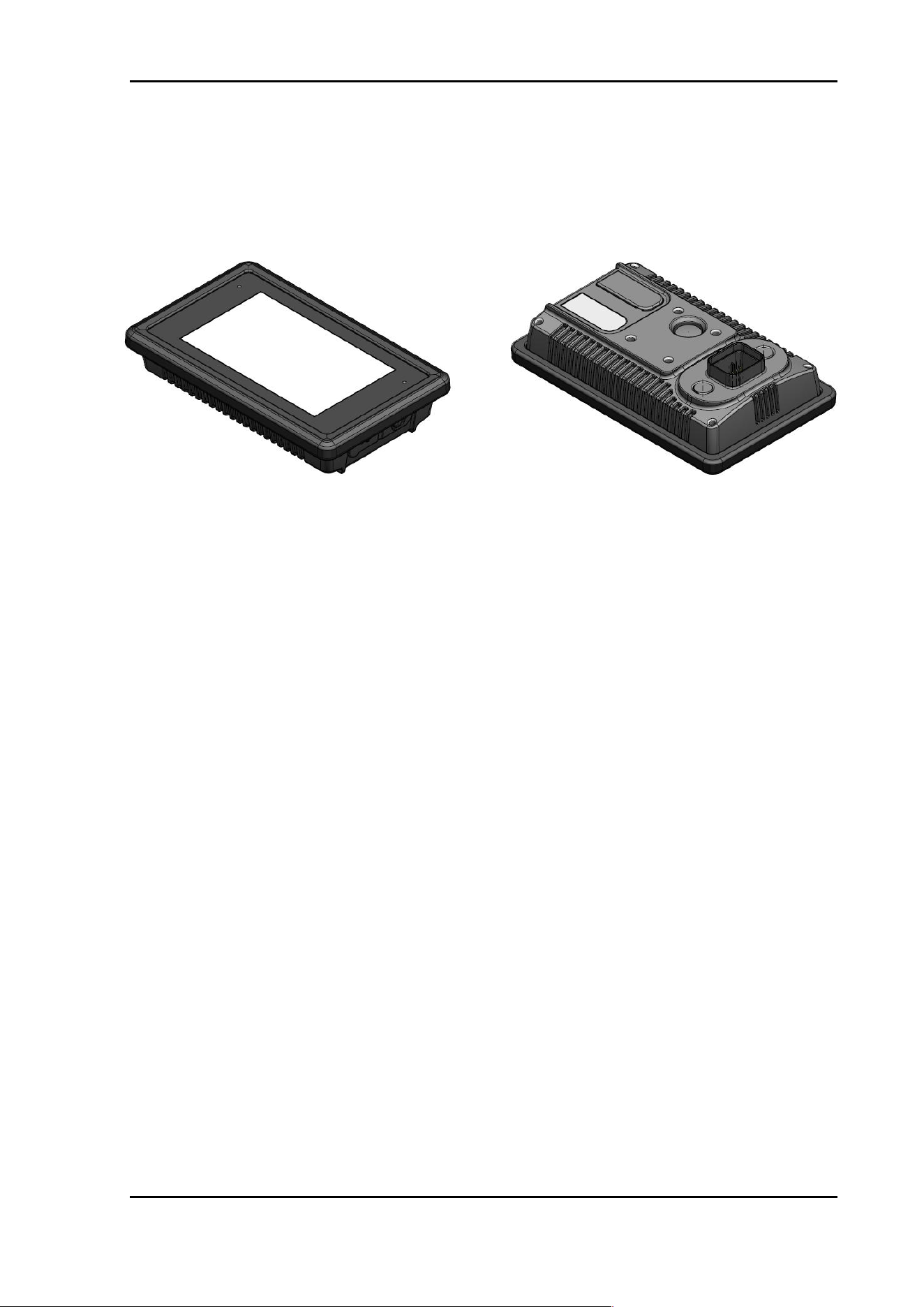
3.2.1 OPUS B3 ECO
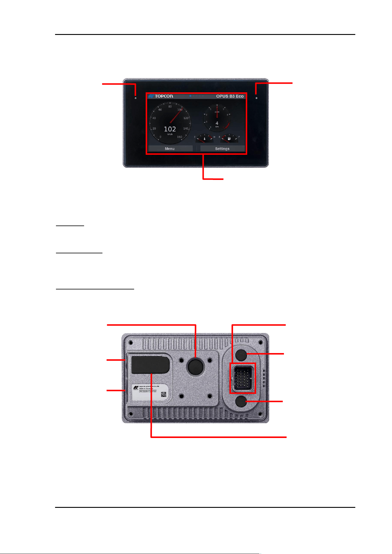
Fig. 3.1: Schematic diagram of the OPUS B3
Display:
5” (800 x 480 px) TFT color graphic LCD display (optional) with capacitive touch.
Light Sensor:
The light sensor can be used for an automatic adaption of display-backlight to the
ambient light intensity.
Multicolor Status LED:
There is one multicolor status LED available.
Fig. 3.4: Schematic diagram of OPUS B3 backside
Multicolor LED
Main connector
Light Sensor
Power button
Service interface
(for service only)
Extension USB interface
(for full and automotive
Ethernet version only)
USB slot
Video interface (for full
and automotive
Ethernet version only)
Ethernet interface (for full
and automotive Ethernet
version only)
Display

Technical Documentation
Page 14
Service interface:
On OPUS B3 there is a service interface available. This interface serves Topcon
internal service use only.
Please do not remove the protection cap of service interface!
OPUS B3 may only be used with factory closed protection cap otherwise Topcon
Electronics GmbH is no liable for any damage or misfunction.
Power button:
The OPUS B3 have a separate power button. This button may be programmable within
the application running on OPUS B3 (see Projektor Tool Online Help, CODESYS
Helpfile). Per default the display will be switched on press and switch off on long press
(> 4 seconds).
Power-on/off behavior:
OPUS B3 can be switch on/off by the power supply directly.
As soon as the device is supplied with the necessary voltage via terminal 30 (battery
plus), terminal 31 (battery GND) and terminal 15 (ignition), it will start to boot. In order
to decrease boot time, the device supports power modes with which you can put the
device in a sleep mode before it powers down.
When ignition voltage is removed, the device will switch to low-power-mode (see
C/C++ Developer Guide). After a time, frame that can be configured (default time is
60 sec) the device will move one more step down to sleep-mode. After another 60
seconds (default time) the unit will fully switch off. As soon as terminal 15 is switched
on again the unit will go back to on-mode in full operation.
Power Mode
current at 12 V DC
current at 27 V
On
≤ 775 mA
≤ 380 mA
Low-power
Depending on
configuration
Depending on
configuration
Sleep
≤ 85 mA
≤ 50 mA
Off
≤ 5 mA
≤ 4 mA
For more information, please refer to the C/C++ Developer Guide.
Extension USB interface (optional):
The OPUS B3 ECO offers extension interface in Full and Automotive Ethernet option
only.
Do not unplug clamp 30 from power supply on running unit.
Power supply interruption on clamp 30 may cause data
corruption and loss.

Technical Documentation
Page 15
On OPUS B3 ECO Basic the option interface is sticked with protection rubber cover.
Please do not remove the protection rubber cover of extension interface!
OPUS B3 may only be used with factory closed protection rubber cover. Otherwise,
Topcon Electronics GmbH& Co KG is no liable for any damage or misfunction.
USB slot:
OPUS B3 offers USB slot on side to be used for software update and data transfer.
Main connector:
The following interfaces are available:
• Power supply and ignition input
• 2 x CAN-Interfaces according to ISO/DIS 11898
• RS232-Interface
• Wake Input (on Full and Automotive Ethernet option only)
• Stereo Audio line out (on Full and Automotive Ethernet option only)

Technical Documentation
Page 16
3.3 Features Overview for OPUS B3
• Encapsulated aluminum housing to be mounted in landscape or portrait mode,
standalone or in dash
• 5” TFT color display for automotive with resolution 800 x 480 pixels
• Capacitive touch screen
• Powerful Freescale I.MX6® Solo 800Mhz CPU
• 32bit processor with embedded Linux operating system (Linux kernel 4.14.0)
• Two CAN interfaces (ISO 11898) using CANopen® and SAE J1939 protocols.
Layer II is supported
• Speaker
• RS232 interface for serial console
• High speed USB on the side
• Wake Input (on Full and Automotive Ethernet option only)
• Stereo Audio line out (on Full and Automotive Ethernet option only)
• Industrial Ethernet / Automotive Ethernet
• Analog Video Input (PAL or NTSC only)
• Power button
The OPUS B3 is particularly characterized by its robust construction, and it has been
developed especially for harsh use conditions in mobile work machines.
The Wake Input is connected to ground (GND) by default. The hardware input is
permanently set to ground and cannot be changed. The signal can be inverted via
software configuration, switching it to floating or 12 V. Please note that the signal must
first be connected to ground in order to switch to 12 V or floating. It is therefore not
possible to avoid the ground circuit directly.
3.4 Application Development
There are three possible ways to program the OPUS B3 and make it an integrated part
of its application.
1. OPUS Projektor:
This powerful development environment provided by Topcon Electronics GmbH
enables the quick and effective creation of an application for the OPUS B3 operator
terminal. Use the Projektor to conveniently design the user interface on the computer,
which can be easily displayed on the device. Additionally, this tool includes features to
work with CANopen
®
, J1939 and CANFreestyle protocols for CAN communication.
For further information please refer to the OPUS Projektor Online Manual.
With ISO devices, the OPUS B3 can be used as an ISO-VT slave in accordance with
the ISO-11783 standard and DLG conformity. The necessary configuration is also
done in the OPUS Projektor.
2. CODESYS 3.x:
CODESYS is a programming tool and system developed by the German company 3S
according to IEC 61131-3 standard. It supports different means of programming such
as FUP or Structured Text. It can be used to program the OPUS B3 and CODESYS
Technical Documentation
Page 17
compatible ECUs. CODESYS includes the functionality to configure the CANopen
®
,
J1939 and CAN Layer 2protocol for communication over CAN bus.
For further information please refer to the Codesys Help File.
3. C-Programming:
OPUS B3 with its embedded Linux operating system can be fully programmed using
C or C++ as programming language.
For further information and function-call list please refer to the C/C++ Developer
Guide.
Please take notice of the following recommendation and prerequisites for the computer
used to the application design and /or programming:
- Using Projektor Tool and CODESYS for the development, it is recommended to
use the PC with Windows 10 or 11 operational system, at least 5 GB free hard
disk capacity and 8 GB RAM.
- Programming with C/C++, Linux operational system is prerequisite.
The operator panel OPUS B3 generation may only be handled due
to the according operation manual.

Technical Documentation
Page 18
3.5 Development Kit
For programming the graphical user interface of the OPUS B3 some different
development kits are provided.
Topcon Toolchain with Projektor Tool
Order number: OPEP00B3CAN
Description
Order Number
Qty
Main connecting cable
OPKAB3CAN15
1
Ethernet cable
1
WE Toolchain download:
- Projektor Tool
- PClient
- Documentation
1
Basic Projektor-Tool training at a
Topcon facility
1
Projektor Tool license
2
12 months technical support
1
CODESYS 3.x
Order number: OPEP00B3CDS
Description
Order Number
Qty
Main connecting cable
OPKAB3CAN15
1
Ethernet cable
1
CODESYS Software download:
- Development Tool
- Application
- Target files
- Documentation
1
Basic CODESYS training at a
Topcon facility
1
12 months technical support
1

Technical Documentation
Page 19
ISO-UT with OPUS Projektor
Order number: OPEP00B3ISO
Description
Order Number
Qty
Main connecting cable
OPKAB3CAN15
1
Ethernet cable
1
ISO-VT software download:
- Projektor Tool
- PClient
- ISO-VT
- Documentation
1
Basic Projektor-Tool training at a
Topcon facility
1
Projektor Tool license
2
12 months technical support
1
Accessories not part of the Developer’s kit:
Description
Order Number
Qty
Video Cable OPUS B3
OPKAA3VID010
1
Ethernet-to-USB adapter
1
Technical Documentation
Page 20
4 Getting Started
4.1 Check the delivered parts
Please check whether all parts described in the scope of delivery have been delivered
correctly. For question or reclamation please contact the support team of Topcon
Electronics GmbH ([email protected]).
4.2 Mounting
The unit is delivered without mounting accessories.
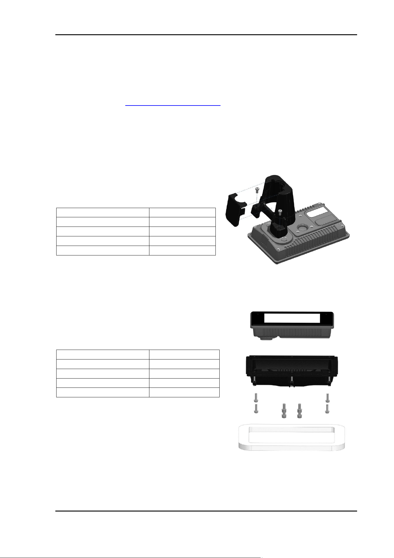
Depending on mounting type the following mounting accessories are available.
Standalone mounting connector cover
(Order number OPUSB3EZBSA000)
In dash mounting cover OPUS B3 ECO
(Order number OPUSB3EZBER000)
Material
PC+ABS
Dimensions
82x52x63 mm
Operating Temperature
-30 …+75 °C
Storage Temperature
-40 …+85 °C
Max mounting torque
1,8 ± 0,2 Nm
Material
PC+ABS
Dimensions
231x152x46 mm
Operating Temperature
-30 …+75 °C
Storage Temperature
-40 …+85 °C
Max mounting torque
2,5 ± 0,2 Nm

Technical Documentation
Page 21
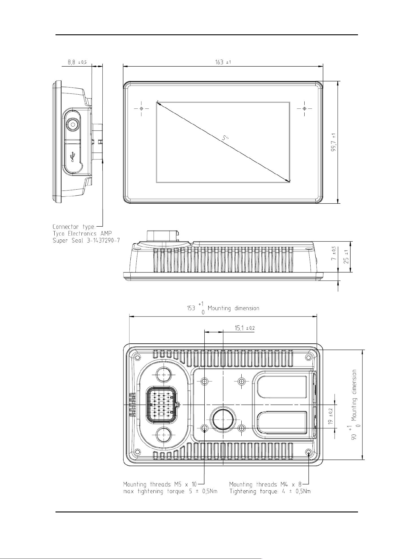
The back side of the unit is ready prepared for both in dash and standalone mounting.
Both portrait and landscape positions are supported for mounting.
For mounting, please follow the instruction provided in the following dimensional
drawing.
Following optional accessories are available for OPUS B3 display.
Removable screen protection foil OPUS B3 ECO
(Order number OPUSB3EZBSF000)
Material
PC+ABS
Dimensions
152,5x89,2 mm
PET Thickness
100 μm
Pencil hardness
2H-3H
Haze
<1,0%
Silicon PSA
25 μm
Operating Temperature
-30 …+75 °C
Storage Temperature
-40 …+85 °C
Technical Documentation
Page 22
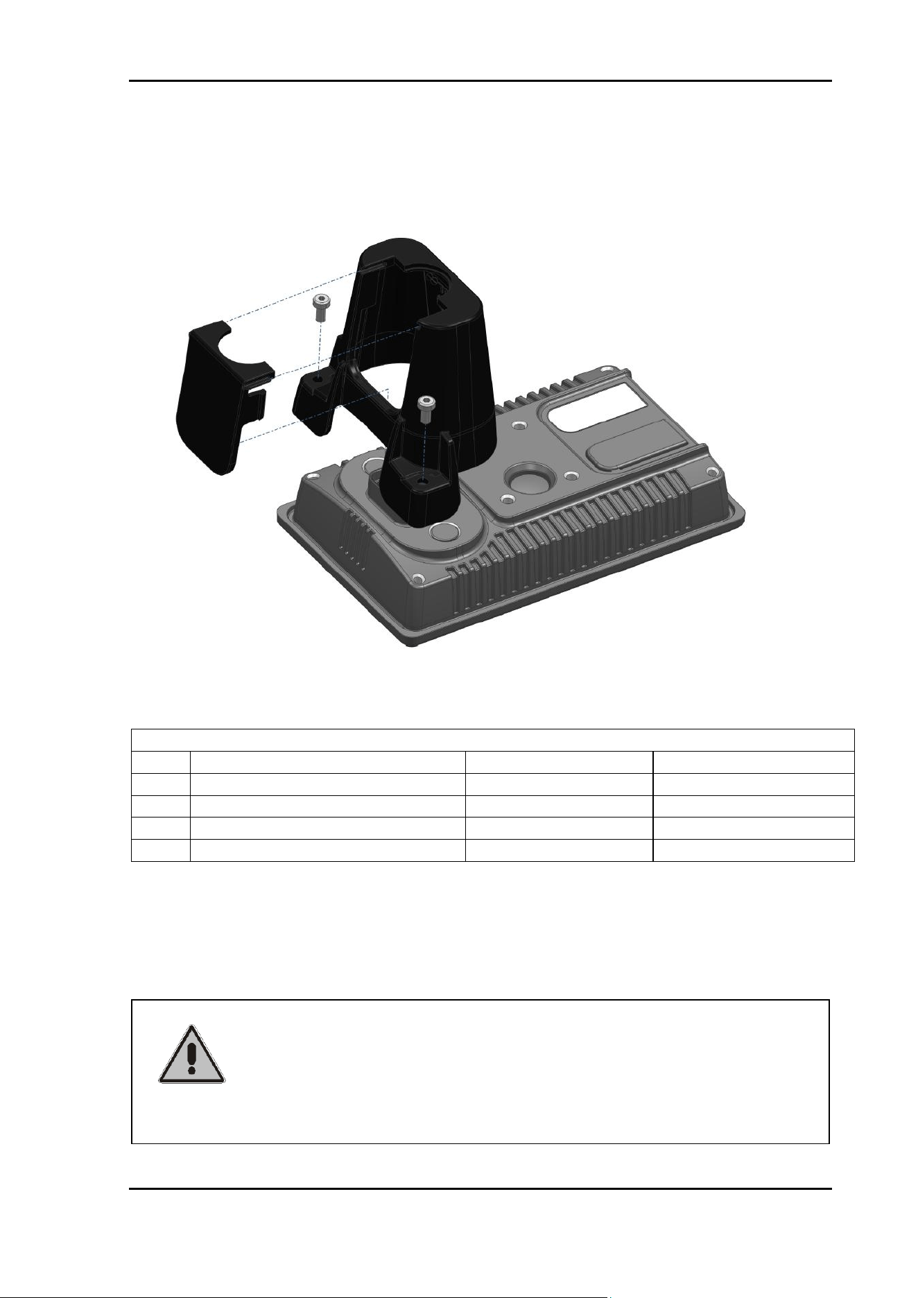
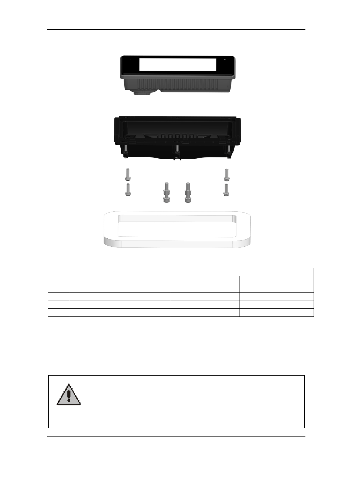
4.2.1 Standalone Mounting Instruction for OPUS B3
1. Thread connector cables through housing
2. Plug in main connector cable
3. Clip side cover plate into housing
4. Screw connector cover to device
Parts List
Pos.
Description
Order number
Supplier
1
OPUS B3 ECO
OPUSB3XX1XXX
Topcon Electronics
2
Dashboard
-
Customer
3
Connector Cover
OPUSB3EZBSA000
Topcon Electronics
4
M4 Screw* (DIN EN ISO 4762)
-
Customer
*Assignment of the screw length depends on dashboard thickness (thickness/length):
1mm – 3mm / M5 x 20
4mm – 6mm / M5 x 24
7mm – 10mm / M5 x 28
Attention!
Using too long screws can damage the unit!
Accepted mounting torque with mounting cover is 1,8 Nm
Please secure the screws with the thread locker medium
strength (e.g. Loctite 243).
Technical Documentation
Page 23
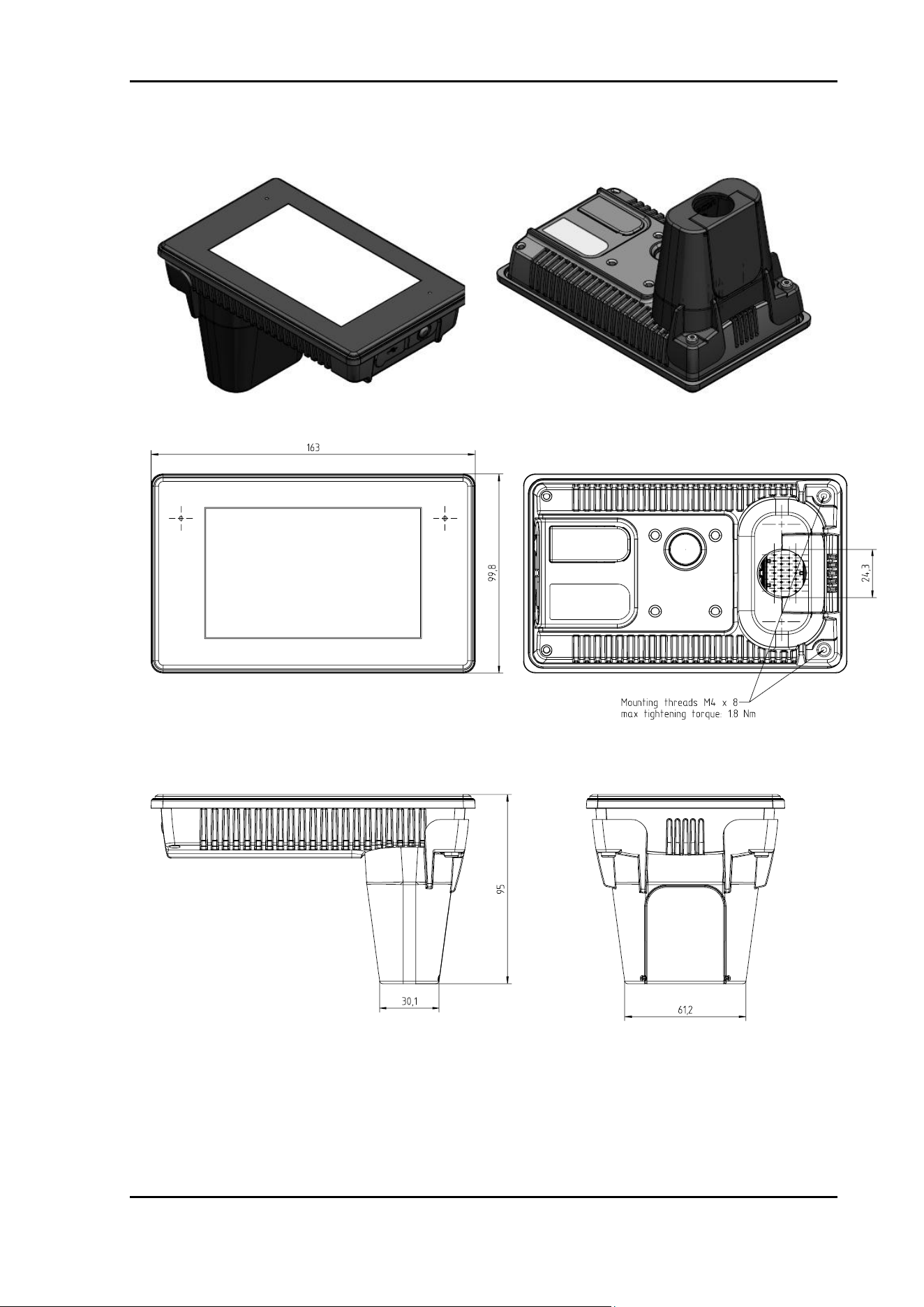
4.2.2 Dashboard Mounting Instruction for OPUS B3
Parts List
Pos.
Description
Order number
Supplier
1
OPUS B3
OPUSB3XX2XXX
Topcon Electronics
2
Dashboard
-
Customer
4
Mounting Cover
OPUSB3EZBER000
Topcon Electronics
5
M4 Screw* (DIN EN ISO 4762)
-
Customer
*Assignment of the screw length depends on dashboard thickness (thickness/length):
1mm – 3mm / M5 x 20
4mm – 6mm / M5 x 24
7mm – 10mm / M5 x 28
Attention!
Using too long screws can damage the unit!
Accepted mounting torque with mounting cover is 1,8 Nm
Please secure the screws with the thread locker medium
strength (e.g. Loctite 243).
Technical Documentation
Page 24
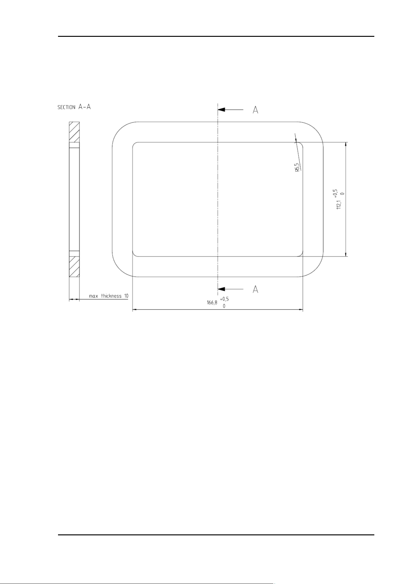
4.2.3 Connector Cover for OPUS B3 ECO
Technical Documentation
Page 25
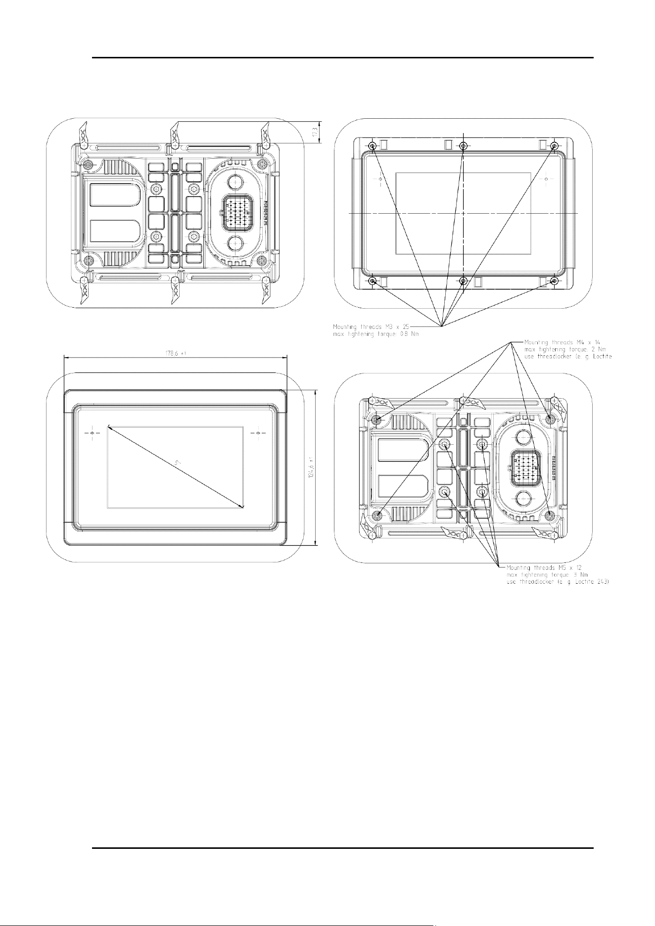
4.2.4 Dashboard Cut-out
Maximum dashboard thickness for mounting OPUS B3 is 10mm
OPUS B3 Eco
Technical Documentation
Page 26
4.2.5 Mounting Cover for OPUS B3 ECO

Technical Documentation
Page 27
4.2.6 Screen Protection Foil for OPUS B3 ECO
Removable screen protection foil is an optional accessory that can be ordered to
protect the display against scratches, water und dust.
Technical Documentation
Page 28
5 Electrical installation OPUS B3
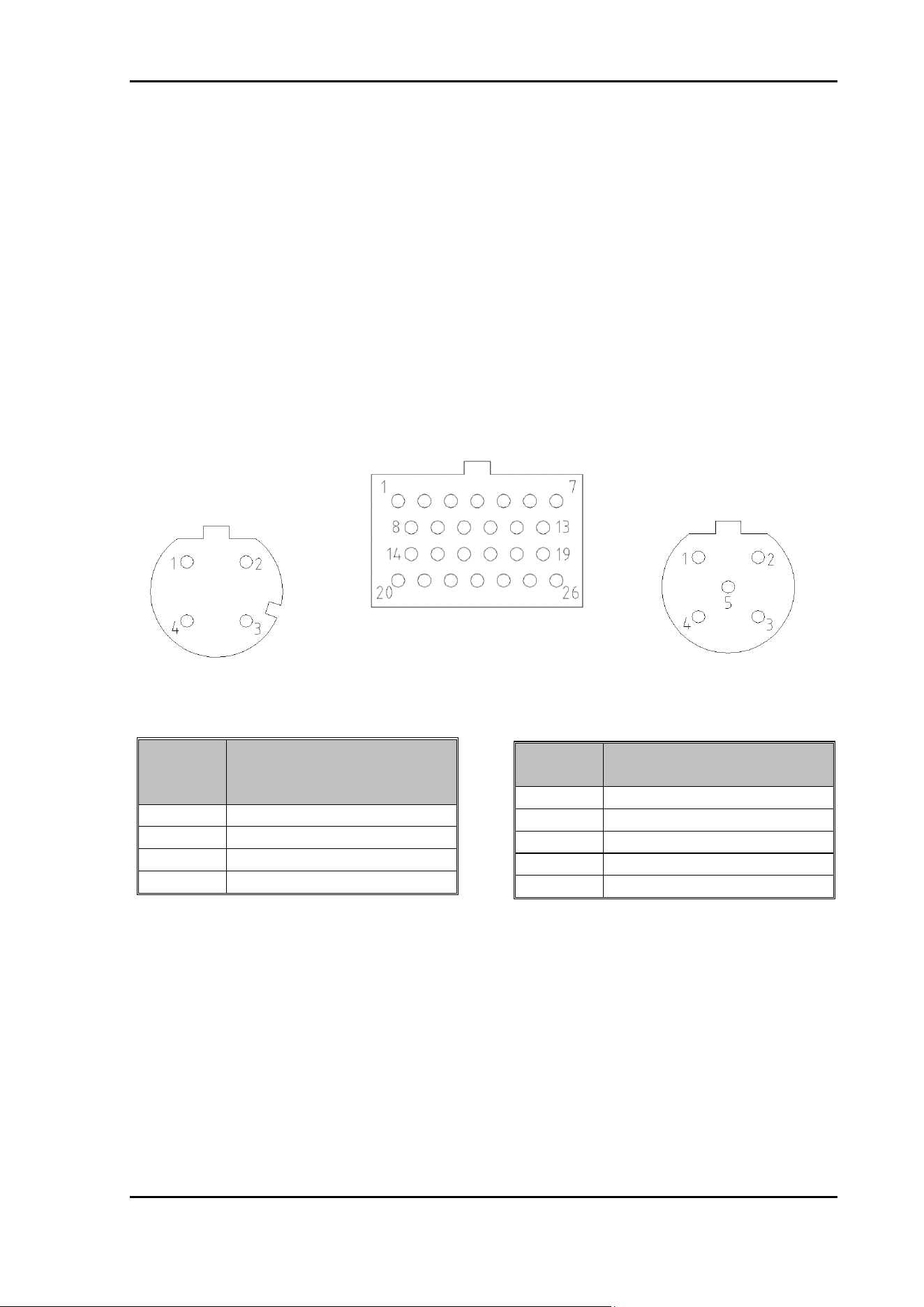
Below you find the pin out diagram of the OPUS B3. The connectors (see fig. 3.3) are
drawn as seen from the back side of the unit.
Please be aware that the existing pins and connectors depend on the hardware option
you ordered.
Please note that the OPUS B3 only represents one part of the entire CAN network.
Set-up and dimensioning of the network must be executed by specialized personnel,
and the information in this regard cannot be a component of this operating manual.
Recommended torque for the M12 connectors is 0.8 ± 0,2 Nm.
Ethernet
Round Connector,
4 pins, M12,
acc. To IEC 61076-2-101
1
TD+
2
RD+
3
TD-
4
RD-
Video
Round Connector, 5
pins, M12
1
VidSig+
2
Mirror
3
Camera+
4
Camera -
5
VidSig GND
Video connector pinout
Ethernet
Connector, M12,
female, 4 pins, d-
coded
Video-
Connector, M12,
female, 5 pins, b-
coded
Main Connector
Ethernet connector pinout

Technical Documentation
Page 29
Main connector pinout (in full option)
pin no.
assignment
description
1
VCC
supply voltage +; terminal 30
2
Ignition Input
ignition input; terminal 15
3
GND
supply voltage - ;terminal 31
4
Wake
Wake Input, “Doorswitch” (optional)
5
Audio Out_L
Audio line out, Stereo (optional)
6
Audio Out_R
Audio line out, Stereo (optional)
7
Audio GND
Audio line out, Ground (optional)
8
CAN1H
CAN bus 1 high signal
9
CAN1L
CAN bus 1 low signal
10
CAN2H
CAN bus 2 high signal
11
CAN2L
CAN bus 2 low signal
12
n.c.
13
n.c.
14
n.c.
15
n.c.
16
RS232: RxD
RS232: RxD
17
RS232: TxD
RS232: TxD
18
RS232: GND
RS232: GND
19
n.c.
20
n.c.
21
n.c.
22
n.c.
23
SERV_EN
service enable; to be connected while power-on for
updating
24
n.c.
25
n.c.
26
n.c.
Please observe the following guidelines for set-up:
• Power supply lines should only be passed in pairs as close together as possible.
• Sensitive signal lines should be shielded to achieve highest possible damping,
and under this shielding they should be still passed twisted.
• Metal plug connections should be used for shielded lines.
• Cable bundles should be distributed in accordance with their purpose (e.g. HF,
LG, and power supply); the groups thus formed should not be routed in parallel
to the extent possible, and they should be routed with clearance.
The OPUS B3 relies on a connection to an ECU that controls the functions and features
of the target vehicle/machine.
Technical Documentation
Page 30
Please keep all the connectors separated. All connection should be done on the
shortest distance to the unit.
5.1 Unused plugs
ACH
TUN
5.2 Power Supply
The unit may be used with the 12 V and for 24 Volt battery systems, operating
voltage range of 8-36 VDC. The overvoltage resistance is about 48V for 2 minutes.
Inverse-polarity protection is up to -48 V DC.
5.3 First steps
Plug in the main connector into the OPUS B3. Then connect the clamps 15 and 30
for the plus voltage, as well as clamps for GND for the ground. Switch on the Power
supply.
On start the boot-logo image will be displayed on the screen. This may be exchanged
with the customer specific image (please refer to C/C++ Developer Guide for more
information).
The boot up takes about 8 seconds and will then call the application according to the
start scripts on the unit (start scripts for Projektor Tool and CODESYS application
already installed by delivery).
The application displays the information of the required application software version.
CODESYS application also contains a simple function test. Each newly downloaded
application will replace the old one automatically.
Penetrating humidity by unused and unprotected plugs may
cause damage of the unit. Please protect unused plugs with the
special blind inserts that have been supplied with the units.
The ECU must be the component in charge of all safety related
functions.
Wrong connection may cause damage of the unit.

Technical Documentation
Page 31
5.4 Cleaning/ service / maintenance
Cleaning agents which have an abrasive or dissolving effect on the coated glass pane,
the foil of the touch screen or the plastic of the encoder or the housing should not be
used to clean OPUS B3 operator panels. Only use soft clothes with a little soap and
water or mild dish washing liquid.
The OPUS B3 does not have any parts that require service by the user. Repairs can
only be performed by Topcon Electronics GmbH.
Technical Documentation
Page 32
6 Technical Documentation
The OPUS B3 is currently available in one housing versions.
OPUS B3 ECO:
Technical Documentation
Page 33
6.1 Dimension Drawings - OPUS B3 Eco

Technical Documentation
Page 34
6.2 Specification
OPUS B3 ECO
Basic
Full
Dashboard Mount
X
X
Dimensions (mm)
H99,7 x W163 x D32
H99,7 x W163 x D32
Display size
800x480 pixels
800x480 pixels
Touchscreen
X
X
Signal LED
1
1
Speaker
X
X
Processor Speed
800 MHz I.MX6
800 MHz, I.MX6
RAM
256 MB DDR3
512 MB DDR3
Mass Storage
2 GB
4 GB
EEPROM
1 kB serial
1 kB serial
CAN bus
2
2
RS232
1
1
USB 2.0 full speed
1
2
Ethernet
X
Video in
1
Real time clock
X
X
Light Sensor
X
X
Audio Out
X
Technical Documentation
Page 35
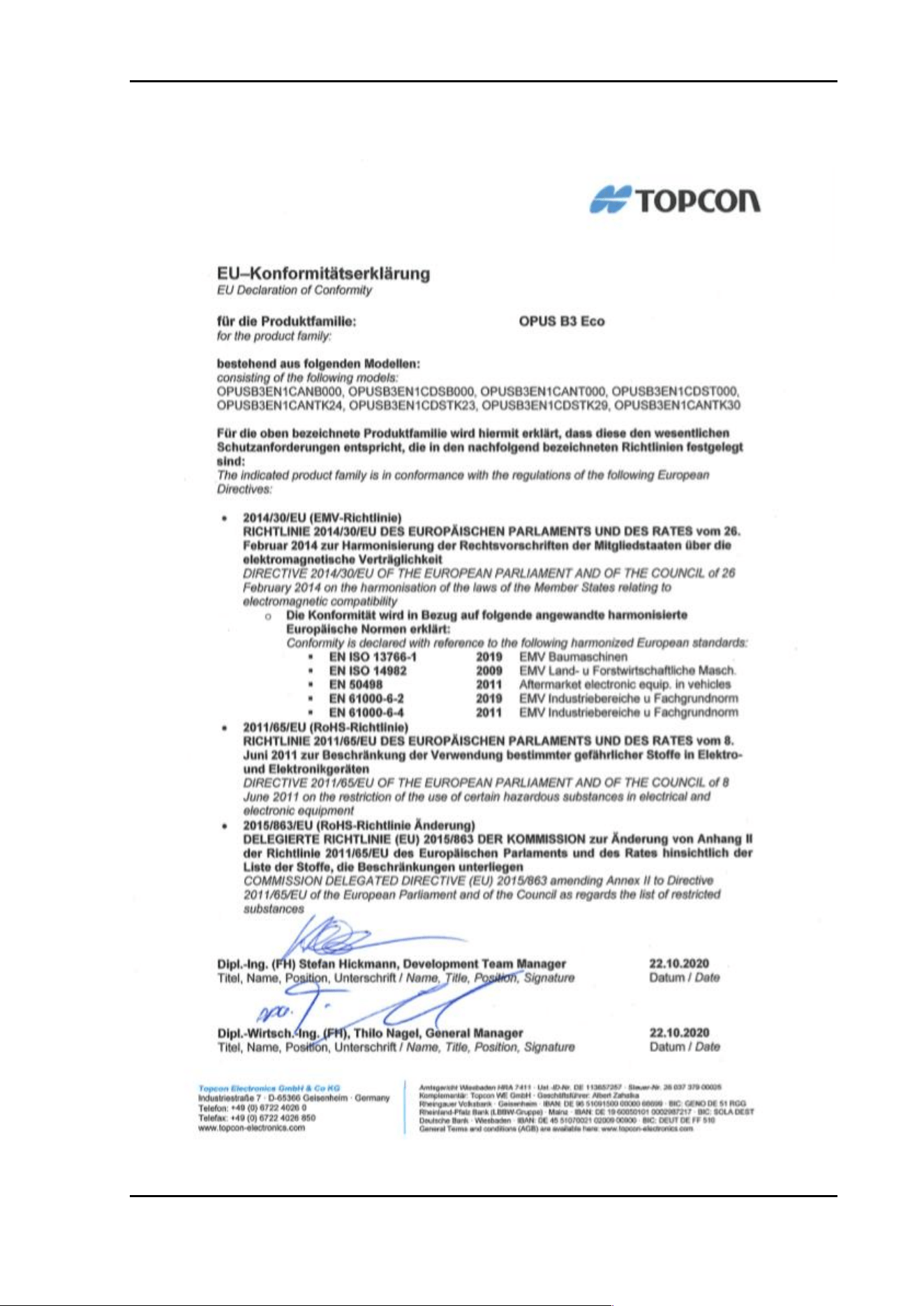
6.3 Declaration of Conformity
6.3.1 Declaration of Conformity for OPUS B3 ECO Basic and Touch
Technical Documentation
Page 36
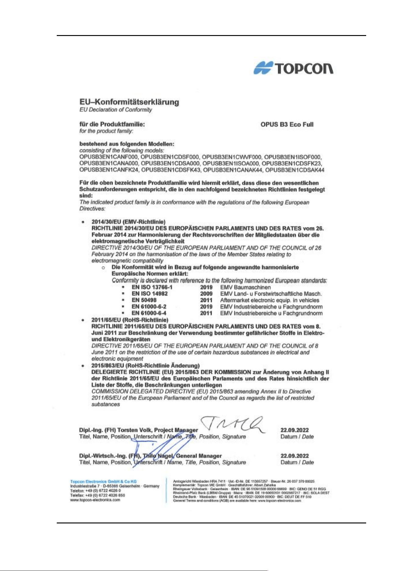
6.3.2 Declaration of Conformity for OPUS B3 ECO Full

Technical Documentation
Page 37
LAST PAGE IS FOR INTERNAL USE ONLY!
NOT TO BE USED WITHIN OFFICIAL RELEASES!
Revision
Revision
Date
Author
Comment
0.1
16.01.2020
KW
New draft
0.2
22.01.2020
AAS
Review
0.3
04.01.2021
NH
New draft
0.4
22.09.2022
KW
Review, correction
0.5
26.09.2022
TV
Review, correction
1.0
26.09.2022
KW
Release
2.0
03.05.2023
KW
Exchange technical drawing in 4.2.5 and release
2.1
16.02.2024
CST
Company name changed, ISO information added,
some cleanup
3.0
23.02.2024
CST
Unification of pages, more ISO information added
3.1
04.11.2025
SHV
More information for Wake Input added
Approval
Dokumenten-Name
OPUS B3 Operating Manual Hardware Description
Status:
Serie
Datum:
26.09.2022
Sharepoint – Revision:
3.0
Datum dieser Revision
26.02.2024
Erstellt:
CST
Geprüft:
CST
Freigegeben:
CST, 26.02.2024