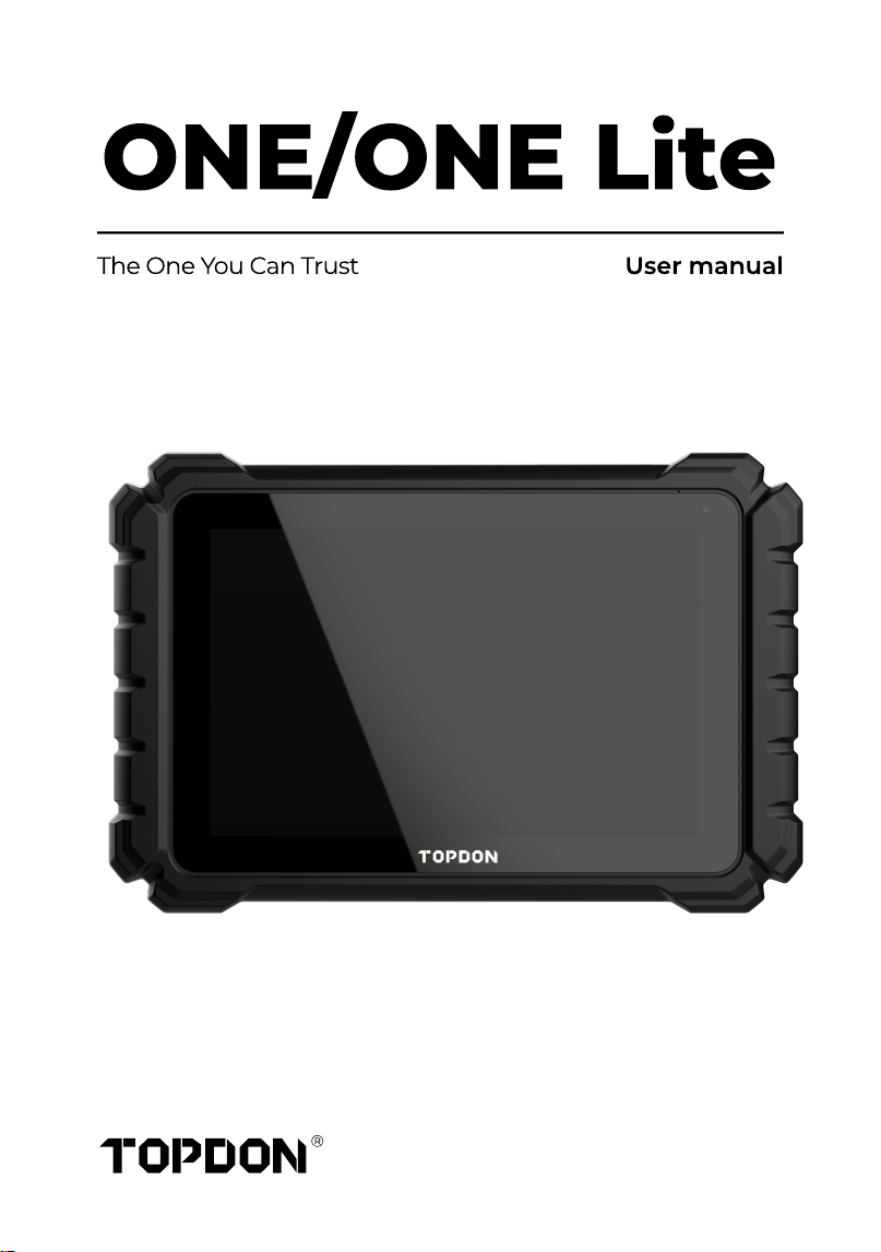
ONE/ONE Lite
The One You Can Trust User manual


SAFETY IS ALWAYS THE FIRST PRIORITY
SECTION 1 WHAT'S IN THE BOX
SECTION 2 PRODUCT OVERVIE
SECTION 3 GETTING STARTE
SECTION 4 USING YOUR TOO
SECTION 5 Technical Specication
SECTION 6 FA
SECTION 7 Warrant
Compliance Information
.......................................................
.......................................................
.......................................................
.......................................................
.......................................................
.......................................................
.......................................................
.......................................................
........................................................
E
1
1
5
5
5
58
Contents

ENGLISH
5
Preface
Welcom
Thank you for purchasing the TOPDON ONE. Please read and understand this
manual carefully before using this product. If any issues arise from the
operation of this product, you are welcome to contact us via
support@topdon.comfor ofcial technical support
About This Manua
The illustrations/pictures/images in this user manual are for reference only. As
products are periodically updated, the actual product you receive may vary
slightly. Please refer to the actual product
All information in this manual is based on the latest information available at the
time of publication and no warranty can be made for its accuracy or
completeness. TOPDON reserves the right to make changes at any time
without notice
The authoritative version of this publication is the English version. In case of any
discrepancies arising from translation errors, the English version shall prevail
Revision History
Versio
1.0
Dat
2025-12
Descriptio
Initial release
6
SAFETY IS ALWAYS THE FIRST PRIORITY!
Read All Instructions Before Use
For your safety, the safety of others, and to avoid any damage to the product
and your vehicle, CAREFULLY READ AND MAKE SURE YOU FULLY
UNDERSTAND ALL THE SAFETY INSTRUCTIONS AND MESSAGES IN THIS
MANUAL BEFORE OPERATING. You must also read the vehicle's service
manual, and observe the stated precautions or instructions before and
during any test or service procedure
Keep yourself, your clothing and other objects away from moving or hot
engine parts and avoid contact with electrical connections
ONLY OPERATE THE VEHICLE IN A WELL-VENTILATED AREA, as the vehicle
produces carbon monoxide, a toxic and poisonous gas, and particulate
matter when the engine is running
ALWAYS WEAR approved SAFETY GOGGLES to prevent damage from sharp
objects and caustic liquids
DO NOT SMOKE OR HAVE ANY FLAMES NEAR THE VEHICLE when testing.
The fuel and battery vapors are highly ammable
DO NOT ATTEMPT TO INTERACT WITH THE PROUDUCT WHILE DRIVING.
Any distraction may cause an accident
TURN THE IGNITION OFF BEFORE CONNECTING OR DISCONNECTING THE
PRODUCT FROM THE VEHICLE's DATA LINK CONNECTOR (DLC) to prevent
causing damage to the product or vehicle's electronic components.
7
SECTION 1 WHAT'S IN THE BOX?
·Table
·ONE VC
·Power Adapte
·OBD-II Extension Cabl
·USB Cable (USB-C to USB-C
·USB Cable (USB-A to USB-C
·Packing Lis
·Quick User Guid
·Carrying Case
8
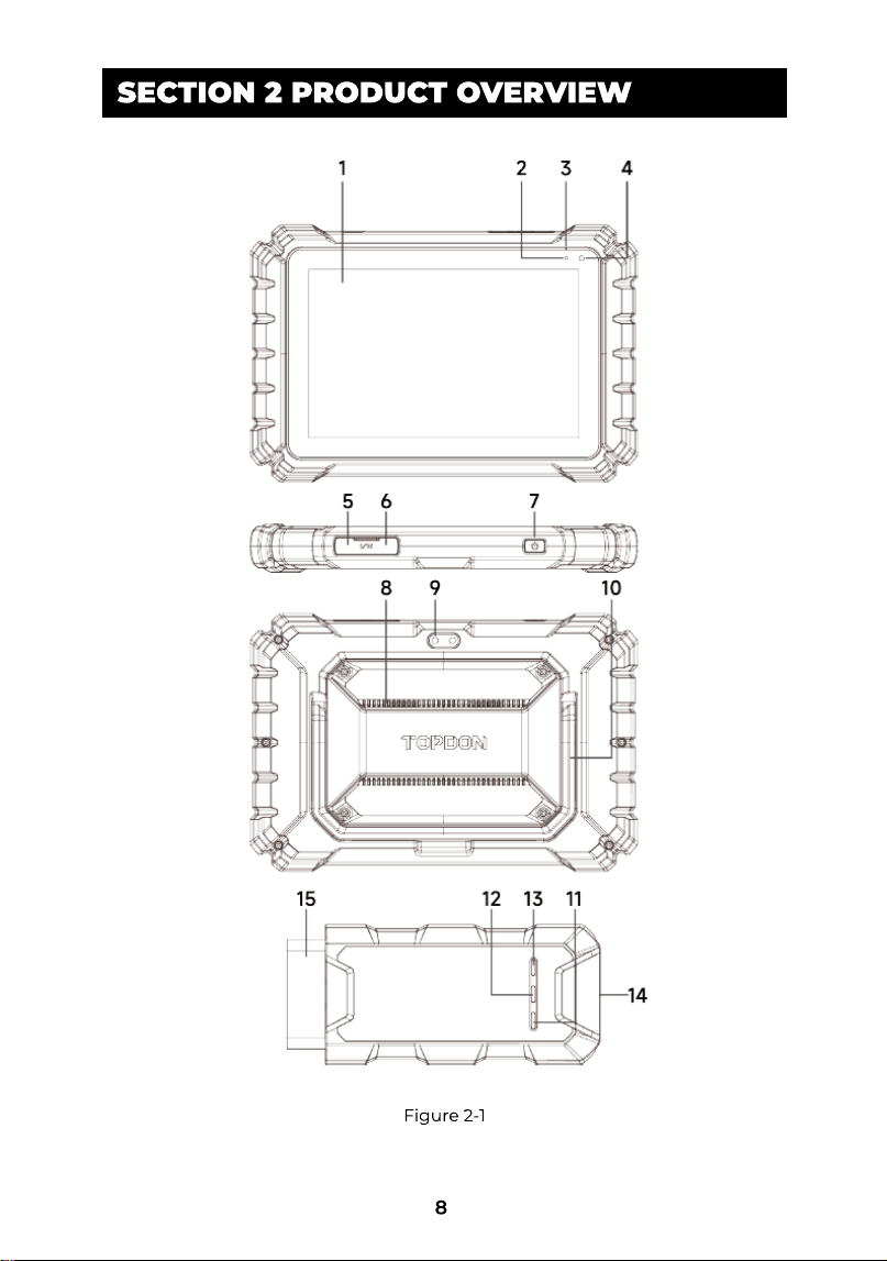
SECTION 2 PRODUCT OVERVIEW
Figure 2-1
9
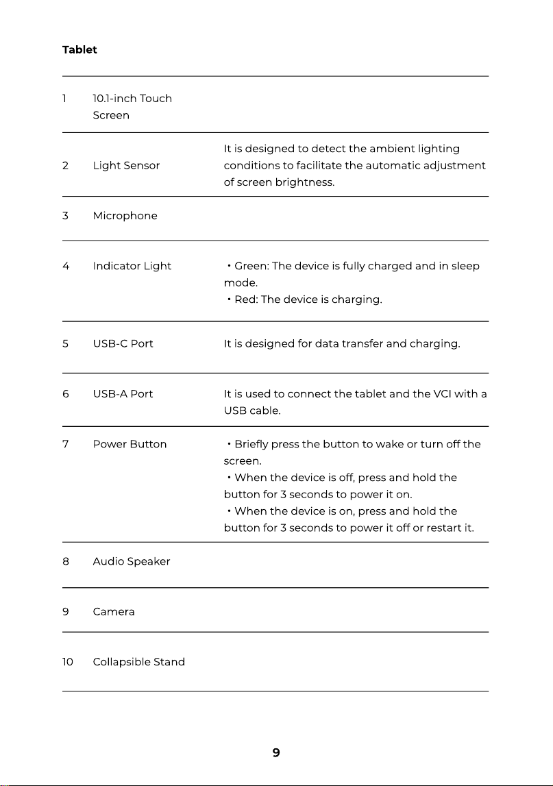
It is designed for data transfer and charging
It is used to connect the tablet and the VCI with a
USB cable
・Briey press the button to wake or turn off the
screen
・When the device is off, press and hold the
button for 3 seconds to power it on
・When the device is on, press and hold the
button for 3 seconds to power it off or restart it
USB-C Por
USB-A Por
Power Butto
Audio Speake
Camer
Collapsible Stan
10
It is designed to detect the ambient lighting
conditions to facilitate the automatic adjustment
of screen brightness
・Green: The device is fully charged and in sleep
mode
・Red: The device is charging.
10.1-inch Touch
Scree
Light Senso
Microphon
Indicator Ligh
Tablet
10
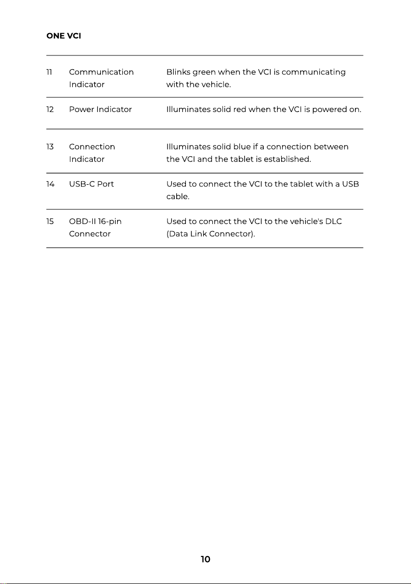
Blinks green when the VCI is communicating
with the vehicle
Illuminates solid red when the VCI is powered on
Illuminates solid blue if a connection between
the VCI and the tablet is established
Used to connect the VCI to the tablet with a USB
cable
Used to connect the VCI to the vehicle's DLC
(Data Link Connector).
Communication
Indicato
Power Indicato
Connection
Indicato
USB-C Por
OBD-II 16-pin
Connector
1
1
1
1
1
ONE VCI
11
SECTION 3 GETTING STARTED
3.1 Basic Setup
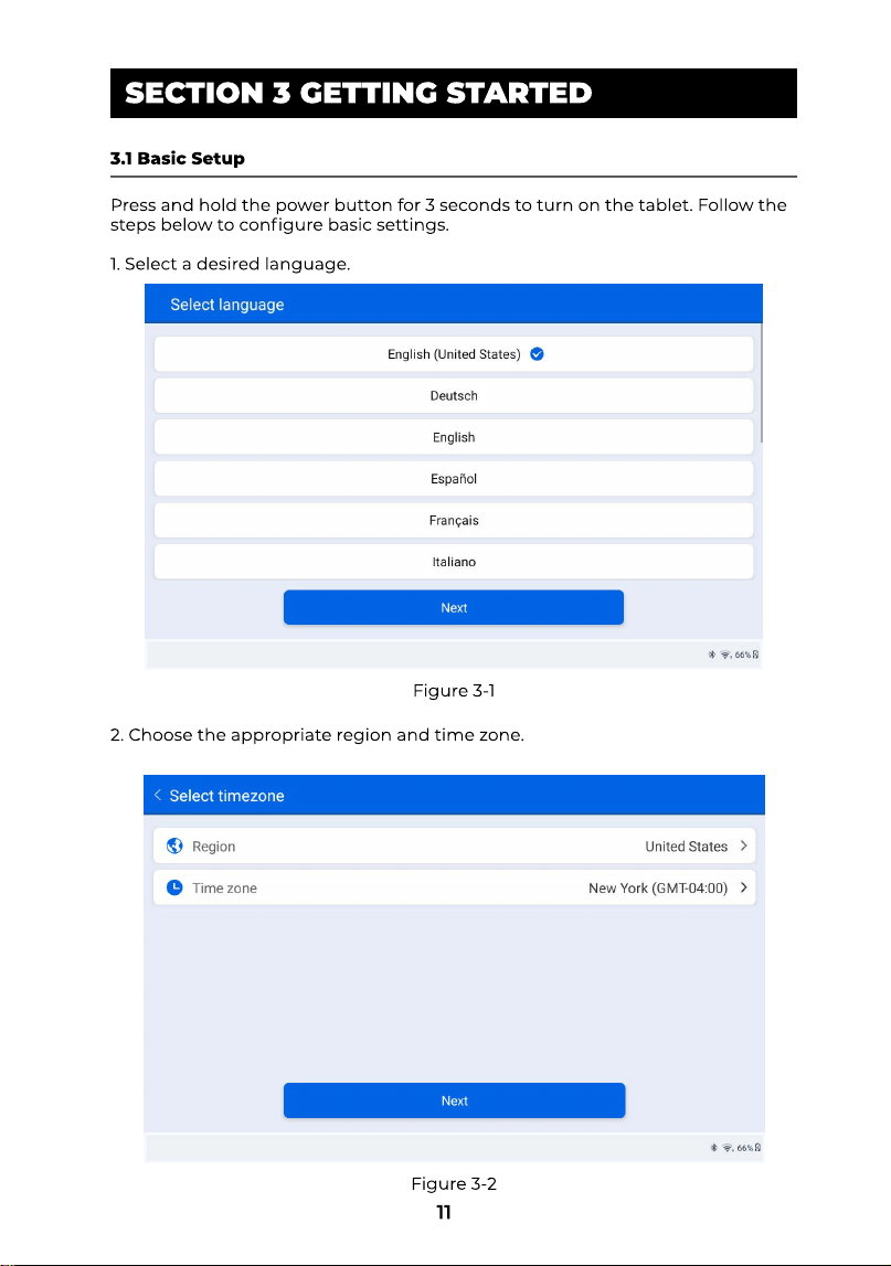
Press and hold the power button for 3 seconds to turn on the tablet. Follow the
steps below to congure basic settings
1.Select a desired language
2.Choose the appropriate region and time zone.
Figure 3-1
Figure 3-2
12
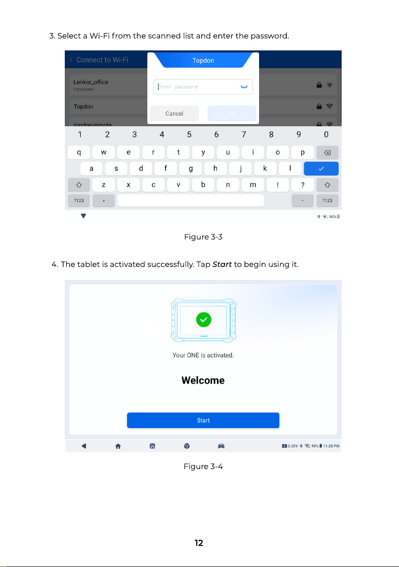
3.Select a Wi-Fi from the scanned list and enter the password
The tablet is activated successfully. Tap Startto begin using it.
Figure 3-3
Figure 3-4
13
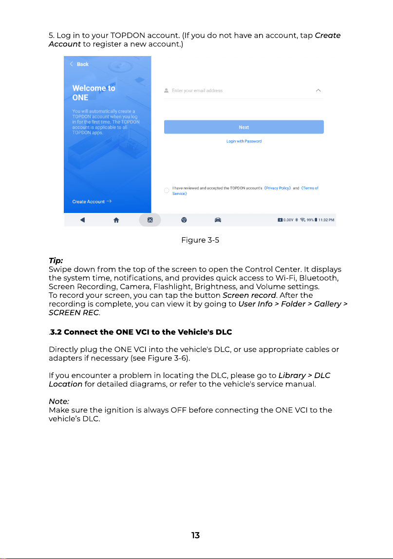
5.Log in to your TOPDON account. (If you do not have an account, tap Create
Accountto register a new account.
Tip
Swipe down from the top of the screen to open the Control Center. It displays
the system time, notications, and provides quick access to Wi-Fi, Bluetooth,
Screen Recording, Camera, Flashlight, Brightness, and Volume settings
To record your screen, you can tap the button Screen record. After the
recording is complete, you can view it by going to User Info > Folder > Gallery >
SCREEN REC.
Figure 3-5
.3.2 Connect the ONE VCI to the Vehicle's DL
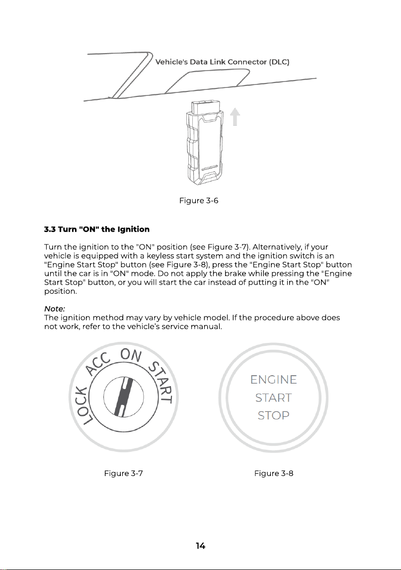
Directly plug the ONE VCI into the vehicle's DLC, or use appropriate cables or
adapters if necessary (see Figure 3-6)
If you encounter a problem in locating the DLC, please go to Library > DLC
Locationfor detailed diagrams, or refer to the vehicle's service manual
Note
Make sure the ignition is always OFF before connecting the ONE VCI to the
vehicle’s DLC.
14
Figure 3-6
3.3 Turn "ON" the Ignitio
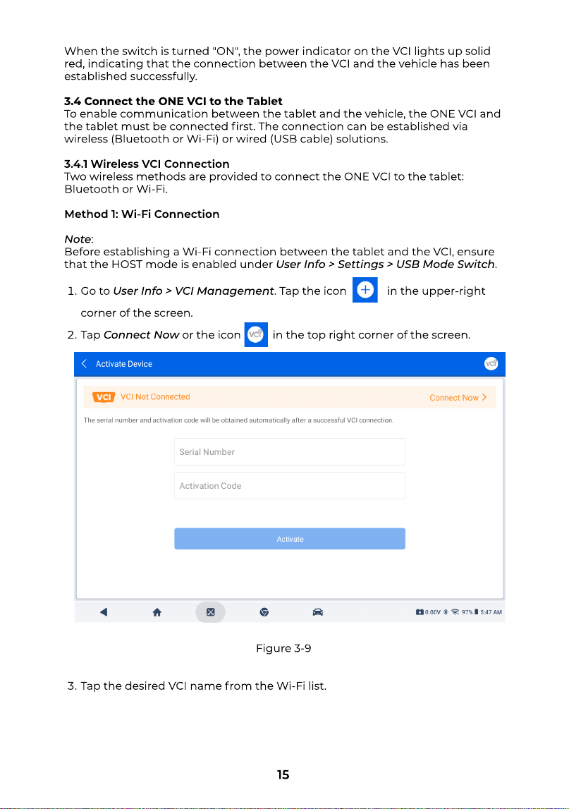
Turn the ignition to the "ON" position (see Figure 3-7). Alternatively, if your
vehicle is equipped with a keyless start system and the ignition switch is an
"Engine Start Stop" button (see Figure 3-8), press the "Engine Start Stop" button
until the car is in "ON" mode. Do not apply the brake while pressing the "Engine
Start Stop" button, or you will start the car instead of putting it in the "ON"
position
Note
The ignition method may vary by vehicle model. If the procedure above does
not work, refer to the vehicle’s service manual.
Figure 3-7 Figure 3-8
15
When the switch is turned "ON", the power indicator on the VCI lights up solid
red, indicating that the connection between the VCI and the vehicle has been
established successfully
3.4 Connect the ONE VCI to the Table
To enable communication between the tablet and the vehicle, the ONE VCI and
the tablet must be connected rst. The connection can be established via
wireless (Bluetooth or Wi-Fi) or wired (USB cable) solutions
3.4.1 Wireless VCI Connectio
Two wireless methods are provided to connect the ONE VCI to the tablet:
Bluetooth or Wi-Fi
Method 1: Wi-Fi Connectio
Note
Before establishing a Wi-Fi connection between the tablet and the VCI, ensure
that the HOST mode is enabled under User Info > Settings > USB Mode Switch
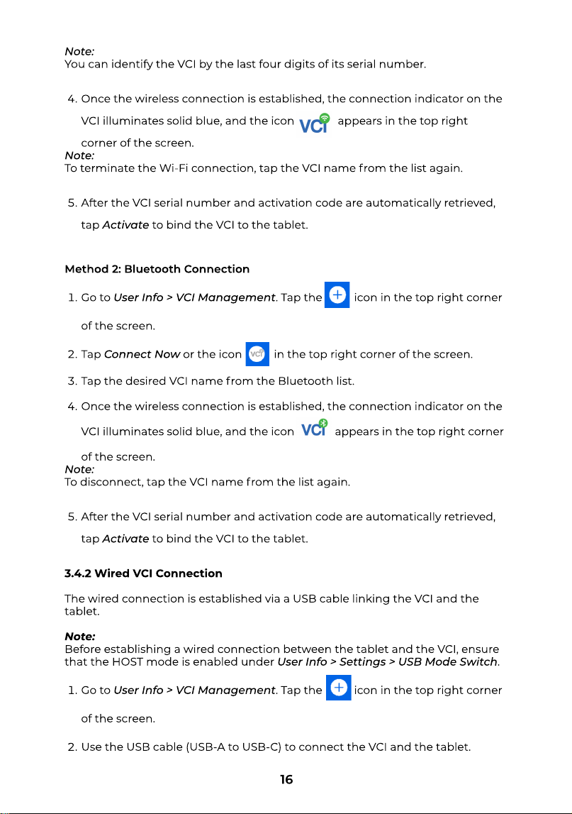
Go to User Info > VCI Management. Tap the icon in the upper-right
corner of the screen
Tap Connect Nowor the icon in the top right corner of the screen
Tap the desired VCI name from the Wi-Fi list.
Figure 3-9
No
t
e
Y
ou can identi
f
y the VC
I
by the last
f
our digits o
f
its serial number
O
nce the wireless connection is established, the connection indicator on the
VC
I
illuminates solid blue, and the icon appears in the top right
corner o
f
the screen
No
t
e
To terminate the Wi-Fi connection, tap the VC
I
name
f
rom the list again
A
f
ter the VC
I
serial number and acti
v
ation code are automatically retrie
v
ed,
tap Ac
t
iva
t
eto bind the VC
I
to the tablet
Meth
o
d
2
: Bluet
oo
th C
o
nnecti
o
Go to User Info > VCI Managemen
t
. Tap the icon in the top right corner
o
f
the screen
Tap Connec
t
Nowor the icon in the top right corner o
f
the screen
Tap the desired VC
I
name
f
rom the Bluetooth list
O
nce the wireless connection is established, the connection indicator on the
VCI illuminates solid blue, and the icon appears in the top right corner
o
f
the screen
No
t
e
To disconnect, tap the VC
I
name
f
rom the list again
A
f
ter the VC
I
serial number and acti
v
ation code are automatically retrie
v
ed,
tap Ac
t
iva
t
eto bind the VC
I
to the tablet
3.4.2 Wired VCI Connectio
The wired connection is established
v
ia a USB cable linking the VCI and the
tablet
Note
Be
f
ore establishing a wired connection between the tablet and the VCI, ensure
that the H
O
ST mode is enabled under User Info > Se
tt
ings > USB Mode Swi
t
ch
Go to User Info > VCI Managemen
t
. Tap the icon in the top right corner
o
f
the screen
Use the USB cable (USB-A to USB-C) to connect the VCI and the tablet
16
17
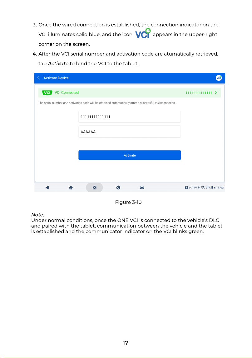
Once the wired connection is established, the connection indicator on the
VCI illuminates solid blue, and the icon appears in the upper-right
corner on the screen
After the VCI serial number and activation code are atumatically retrieved,
tap Activateto bind the VCI to the tablet
Note
Under normal conditions, once the ONE VCI is connected to the vehicle’s DLC
and paired with the tablet, communication between the vehicle and the tablet
is established and the communicator indicator on the VCI blinks green.
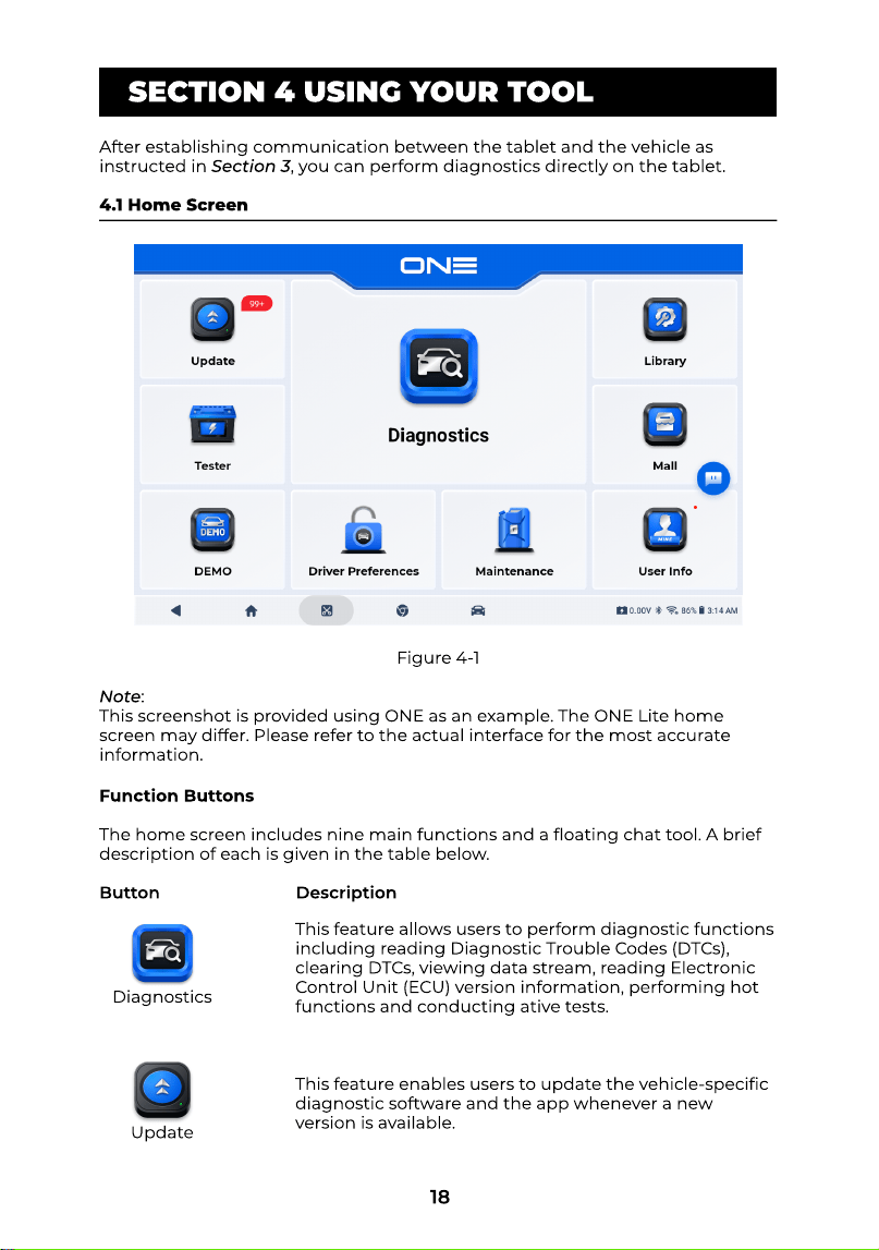
Figure 3-10
18
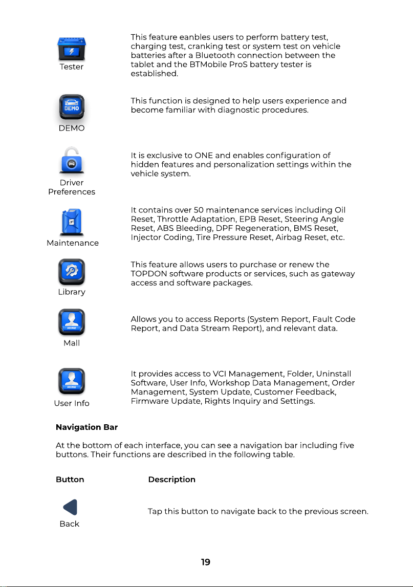
Figure 4-1
SECTION 4 USING YOUR TOOL
After establishing communication between the tablet and the vehicle as
instructed in Section 3, you can perform diagnostics directly on the tablet
4.1 Home Screen
Note:
This screenshot is provided using ONE as an example. The ONE Lite home
screen may differ. Please refer to the actual interface for the most accurate
information.
Function Button
The home screen includes nine main functions and a oating chat tool. A brief
description of each is given in the table below
This feature allows users to perform diagnostic functions
including reading Diagnostic Trouble Codes (DTCs),
clearing DTCs, viewing data stream, reading Electronic
Control Unit (ECU) version information, performing hot
functions and conducting ative tests
This feature enables users to update the vehicle-specic
diagnostic software and the app whenever a new
version is available
Diagnostics
Update
Button Description
19
This feature eanbles users to perform battery test,
charging test, cranking test or system test on vehicle
batteries after a Bluetooth connection between the
tablet and the BTMobile ProS battery tester is
established
This function is designed to help users experience and
become familiar with diagnostic procedures
It is exclusive to ONE and enables conguration of
hidden features and personalization settings within the
vehicle system
It contains over 50 maintenance services including Oil
Reset, Throttle Adaptation, EPB Reset, Steering Angle
Reset, ABS Bleeding, DPF Regeneration, BMS Reset,
Injector Coding, Tire Pressure Reset, Airbag Reset, etc
This feature allows users to purchase or renew the
TOPDON software products or services, such as gateway
access and software packages
Allows you to access Reports (System Report, Fault Code
Report, and Data Stream Report), and relevant data
It provides access to VCI Management, Folder, Uninstall
Software, User Info, Workshop Data Management, Order
Management, System Update, Customer Feedback,
Firmware Update, Rights Inquiry and Settings.
DEMO
Driver
Preferences
Maintenance
Library
Mall
User Info
Tester
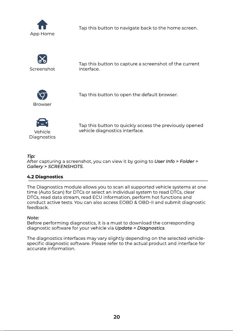
Navigation Ba
At the bottom of each interface, you can see a navigation bar including ve
buttons. Their functions are described in the following table.
Tap this button to navigate back to the previous screen
Back
Button Description
20
Tap this button to navigate back to the home screen
Tap this button to capture a screenshot of the current
interface
Tap this button to open the default browser
Tap this button to quickly access the previously opened
vehicle diagnostics interface
App Home
Screenshot
Browser
Vehicle
Diagnostics
Tip
After capturing a screenshot, you can view it by going to User Info > Folder >
Gallery > SCREENSHOTS
4.2 Diagnostic
The Diagnosticsmodule allows you to scan all supported vehicle systems at one
time (Auto Scan) for DTCs or select an individual system to read DTCs, clear
DTCs, read data stream, read ECU information, perform hot functions and
conduct active tests. You can also access EOBD & OBD-II and submit diagnostic
feedback
Note
Before performing diagnostics, it is a must to download the corresponding
diagnostic software for your vehicle via Update > Diagnostics
The diagnostics interfaces may vary slightly depending on the selected vehicle-
specic diagnostic software. Please refer to the actual product and interface for
accurate information.
21
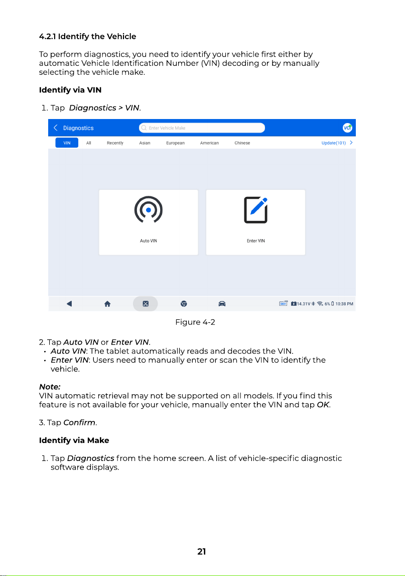
Figure 4-2
4.2.1 Identify the Vehicl
To perform diagnostics, you need to identify your vehicle rst either by
automatic Vehicle Identication Number (VIN) decoding or by manually
selecting the vehicle make
Identify via VI
Tap Diagnostics> VIN.
2.Tap Auto VINor Enter VIN
Auto VIN: The tablet automatically reads and decodes the VIN
Enter VIN: Users need to manually enter or scan the VIN to identify the
vehicle
Note
VIN automatic retrieval may not be supported on all models. If you nd this
feature is not available for your vehicle, manually enter the VIN and tap OK
3.Tap Conrm
Identify via Mak
Tap Diagnosticsfrom the home screen. A list of vehicle-specic diagnostic
software displays.
22
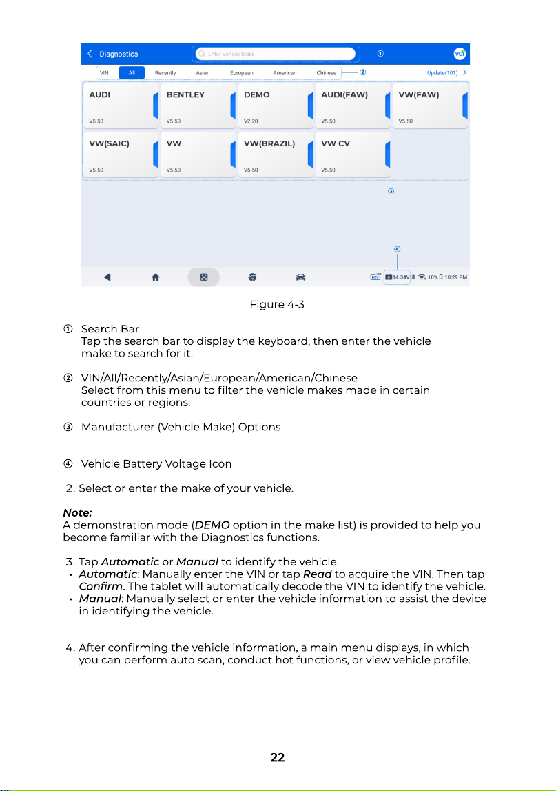
Figure 4-3
④
Search Ba
Tap the search bar to display the keyboard, then enter the vehicle
make to search for it
VIN/All/Recently/Asian/European/American/Chines
Select from this menu to lter the vehicle makes made in certain
countries or regions
Manufacturer (Vehicle Make) Option
Vehicle Battery Voltage Icon
Select or enter the make of your vehicle
Note
A demonstration mode (DEMOoption in the make list) is provided to help you
become familiar with the Diagnostics functions
Tap Automaticor Manualto identify the vehicle
Automatic: Manually enter the VIN or tap Readto acquire the VIN. Then tap
Conrm. The tablet will automatically decode the VIN to identify the vehicle
Manual: Manually select or enter the vehicle information to assist the device
in identifying the vehicle
After conrming the vehicle information, a main menu displays, in which
you can perform auto scan, conduct hot functions, or view vehicle prole.
23
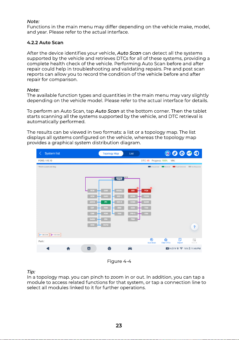
Figure 4-4
Note
Functions in the main menu may differ depending on the vehicle make, model,
and year. Please refer to the actual interface
4.2.2 Auto Sca
After the device identies your vehicle, Auto Scancan detect all the systems
supported by the vehicle and retrieves DTCs for all of these systems, providing a
complete health check of the vehicle. Performing Auto Scan before and after
repair could help in troubleshooting and validating repairs. Pre and post scan
reports can allow you to record the condition of the vehicle before and after
repair for comparison
Note
The available function types and quantities in the main menu may vary slightly
depending on the vehicle model. Please refer to the actual interface for details
To perform an Auto Scan, tap Auto Scanat the bottom corner. Then the tablet
starts scanning all the systems supported by the vehicle, and DTC retrieval is
automatically performed
The results can be viewed in two formats: a list or a topology map. The list
displays all systems congured on the vehicle, whereas the topology map
provides a graphical system distribution diagram.
Tip
In a topology map. you can pinch to zoom in or out. In addition, you can tap a
module to access related functions for that system, or tap a connection line to
select all modules linked to it for further operations
24
Button Descriptio
Clear DTC
Tap the button to clear all the DTCs retrieved
Report
Tap the button to save the current scan results in report format. (To view the
saved reports, go to User Info > Folder > Diagnostic Report > System Report.
Show All / Show Actua
Tap the button to toggle between showing all vehicle systems and showing
only the supported systems
4.2.3 Performing Individual System Diagnostic
Apart from Auto Scan, you can also select an individual system from the
topology or system list to read DTCs, clear DTCs, read data stream, read ECU
information and conduct active tests for that particular system
Note
Depending on the vehicle make, model and year, some functions may not be
available.
ECU Inf
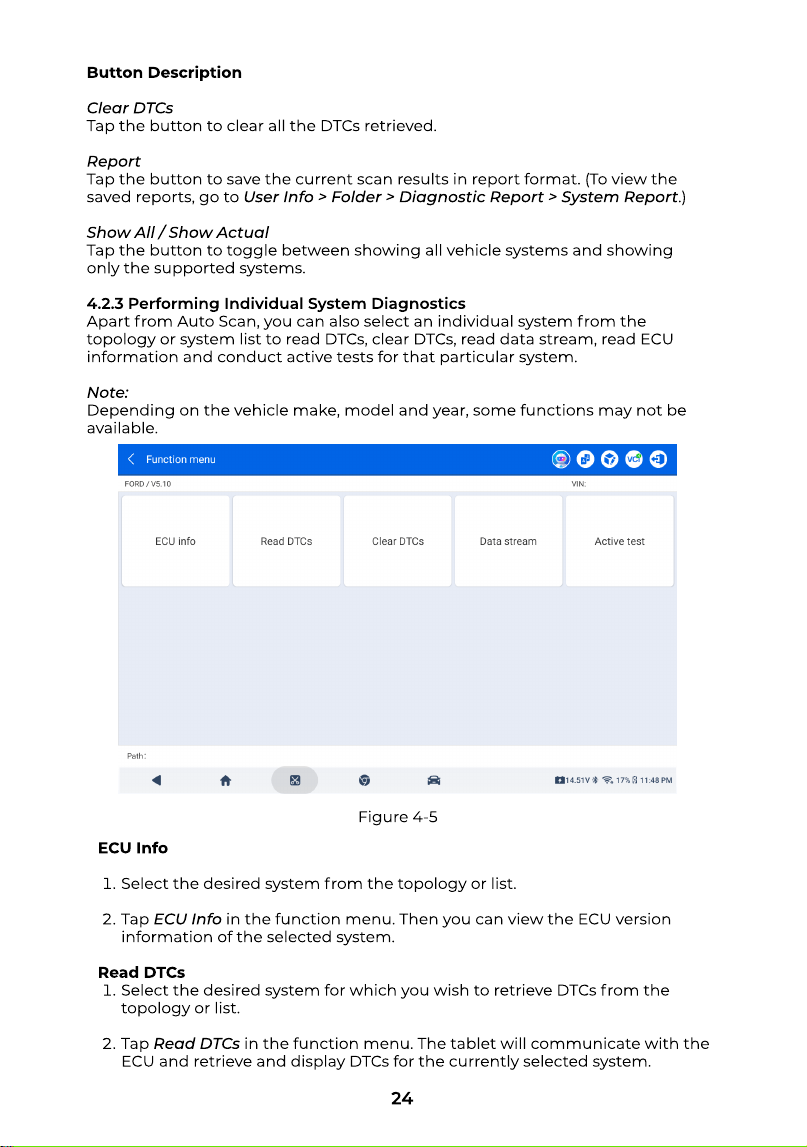
Select the desired system from the topology or list
Tap ECU Infoin the function menu. Then you can view the ECU version
information of the selected system
Read DTC
Select the desired system for which you wish to retrieve DTCs from the
topology or list
Tap Read DTCsin the function menu. The tablet will communicate with the
ECU and retrieve and display DTCs for the currently selected system.
Figure 4-5
25
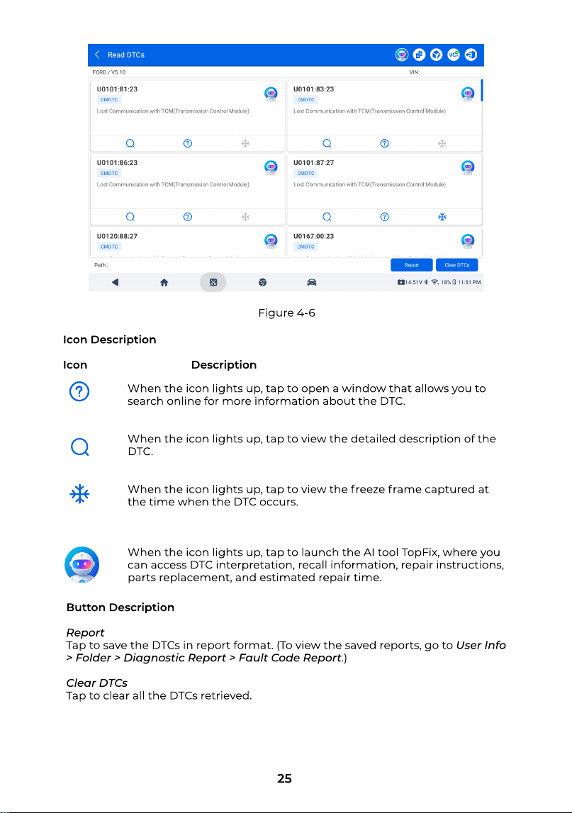
Figure 4-6
Icon Descriptio
Icon Description
When the icon lights up, tap to open a window that allows you to
search online for more information about the DTC
When the icon lights up, tap to view the detailed description of the
DTC
When the icon lights up, tap to view the freeze frame captured at
the time when the DTC occurs
When the icon lights up, tap to launch the AI tool TopFix, where you
can access DTC interpretation, recall information, repair instructions,
parts replacement, and estimated repair time.
Button Descriptio
Repor
Tap to save the DTCs in report format. (To view the saved reports, go to User Info
> Folder > Diagnostic Report > Fault Code Report.
Clear DTC
Tap to clear all the DTCs retrieved
26
Clear DTC
Select the desired system from the topology or list
Tap Clear DTCsin the function menu
Tap OKafter the DTCs are cleared
Note
The procedure of clearing DTCs should be performed after the required
repair has been carried out. Once conrmed, DTCs and freeze data stored in
the ECU will be cleared
DO NOT START UP THE ENGINE WHILE CLEARING DTCS
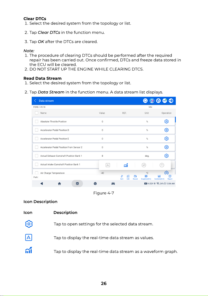
Read Data Strea
Select the desired system from the topology or list
Tap Data Streamin the function menu. A data stream list displays.
Icon Description
Tap to open settings for the selected data stream
Tap to display the real-time data stream as values
Tap to display the real-time data stream as a waveform graph
Icon Description
Figure 4-7
27
Tap to switch between metric and imperial units
Tap to open the online help for the data stream.
Button Descriptio
Sor
Tap to customize the sorting of the data streams
Edi
Tap once to display only the selected data stream. Tap twice to display all
available data streams
Recor
Tap to record and save real-time data stream information. To view the saved
data stream recording, go to User Info > Folder > Replay Data
Grap
Tap to display multiple data streams in separate graphs
Combin
Tap to combine multiple data streams in one graph for easier observation and
comparison
Repor
Tap to save the current data stream values in report format. To view the saved
reports, go to Folder > Diagnostic Report > Data Stream Report
Warning
IF THE VEHICLE MUST BE DRIVEN TO VIEW THE LIVE DATA STREAM, ALWAYS
HAVE A SECOND PERSON HELPING YOU. DO NOT WATCH THE DATA STREAM
WHILE DRIVING
Active Tes
Active Testallows you to manually control certain component operations
directly from the app to verify the operations of components
1.After the vehicle is identied, select the system for which you wish to perform
active test from the topology or list
2.Tap Active testin the function menu. Then you can perform related active
tests as needed
Note
Available active tests vary by vehicle make, year and model.
28
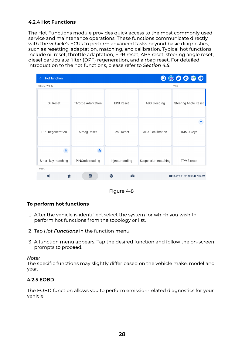
4.2.4 Hot Function
The Hot Functionsmodule provides quick access to the most commonly used
service and maintenance operations. These functions communicate directly
with the vehicle’s ECUs to perform advanced tasks beyond basic diagnostics,
such as resetting, adaptation, matching, and calibration. Typical hot functions
include oil reset, throttle adaptation, EPB reset, ABS reset, steering angle reset,
diesel particulate lter (DPF) regeneration, and airbag reset. For detailed
introduction to the hot functions, please refer to Section 4.5.
To perform hot function
After the vehicle is identied, select the system for which you wish to
perform hot functions from the topology or list
Tap Hot Functionsin the function menu
A function menu appears. Tap the desired function and follow the on-screen
prompts to proceed
Note
The specic functions may slightly differ based on the vehicle make, model and
year
4.2.5 EOB
The EOBD function allows you to perform emission-related diagnostics for your
vehicle.
Figure 4-8
29
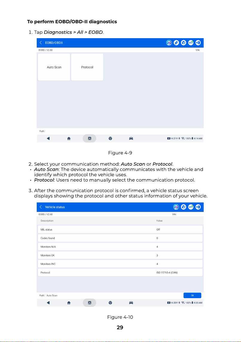
To perform EOBD/OBD-II diagnostic
Tap Diagnostics > All > EOBD.
Select your communication method: Auto Scanor Protocol
Auto Scan: The device automatically communicates with the vehicle and
identify which protocol the vehicle uses
Protocol: Users need to manually select the communication protocol
After the communication protocol is conrmed, a vehicle status screen
displays showing the protocol and other status information of your vehicle
Figure 4-9
Figure 4-10
30
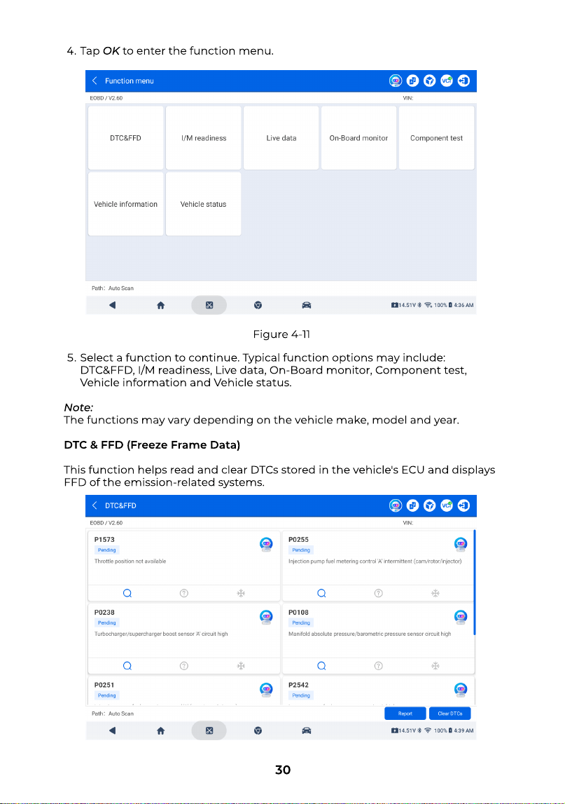
Tap OKto enter the function menu.
Figure 4-11
Select a function to continue. Typical function options may include:
DTC&FFD, I/M readiness, Live data, On-Board monitor, Component test,
Vehicle information and Vehicle status
Note
The functions may vary depending on the vehicle make, model and year
DTC & FFD (Freeze Frame Data
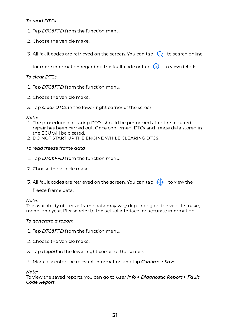
This function helps read and clear DTCs stored in the vehicle's ECU and displays
FFD of the emission-related systems.
31
To read DTC
Tap DTC&FFDfrom the function menu
Choose the vehicle make
All fault codes are retrieved on the screen. You can tap to search online
for more information regarding the fault code or tap to view details
To clear DTC
Tap DTC&FFDfrom the function menu
Choose the vehicle make
Tap Clear DTCsin the lower-right corner of the screen
Note
The procedure of clearing DTCs should be performed after the required
repair has been carried out. Once conrmed, DTCs and freeze data stored in
the ECU will be cleared
DO NOT START UP THE ENGINE WHILE CLEARING DTCS
To read freeze frame dat
Tap DTC&FFDfrom the function menu
Choose the vehicle make
All fault codes are retrieved on the screen. You can tap to view the
freeze frame data
Note
The availability of freeze frame data may vary depending on the vehicle make,
model and year. Please refer to the actual interface for accurate information
To generate a repor
Tap DTC&FFDfrom the function menu
Choose the vehicle make
Tap Reportin the lower-right corner of the screen
Manually enter the relevant information and tap Conrm > Save
Note
To view the saved reports, you can go to User Info > Diagnostic Report > Fault
Code Report.
32
I/M Readines
This function checks whether or not the various emission-related systems on
the vehicle operate properly, and are ready for I/M testing. It can also be used to
check the monitor running status and to conrm if the repair of a car fault has
been performed correctly
Live Dat
This function displays the real-time data stream and parameters from the
vehicle’s ECU
To read the real-time data strea
Tap Live Datafrom the function menu
A list of real-time data streams is displayed. You can view details, record data
stream, combine up to four data streams in one graph for comparison and
generate reports. For detailed operating instructions, please refer to the part
Read Data Streamin Section 4.2.3
On-Board Monito
This function displays the test results for emission-related powertrain
components and systems that are not continuously monitored
Component Tes
This function helps send control commands to the vehicle's ECU as a way to test
and operate the system parts and components
Note
Component tests may not be supported on some vehicles, and available tests
may vary depending on the vehicle make, model, and year. Please refer to the
actual interface for details
Vehicle Informatio
This function contains information (provided by the vehicle manufacturer) from
the vehicle’s ECU
To view vehicle general informatio
Tap Vehicle informationfrom the function menu
Tap Vehicle general information
A menu is displayed. Select the desired option to view details
Vehicle ID number (VIN
Calibration ID (CID
Calibration verication numbers (CVN
ECU name
33
To view vehicle enhance informatio
Tap Vehicle informationfrom the function menu
Tap Vehicle enhance information
Tap In-sue performance tracking for spark ignition engines (IUPR)for details
Vehicle Statu
This function displays the status of the vehicle, including Engine, Transmission,
Codes Found, MIL Status, Monitors and Protocol
4.2.5 Diagnostic Toolbar
After accessing the diagnostics interfaces, a tool bar is displayed in the upper-
right corner of the screen. This section presents a brief introduction to these
tools
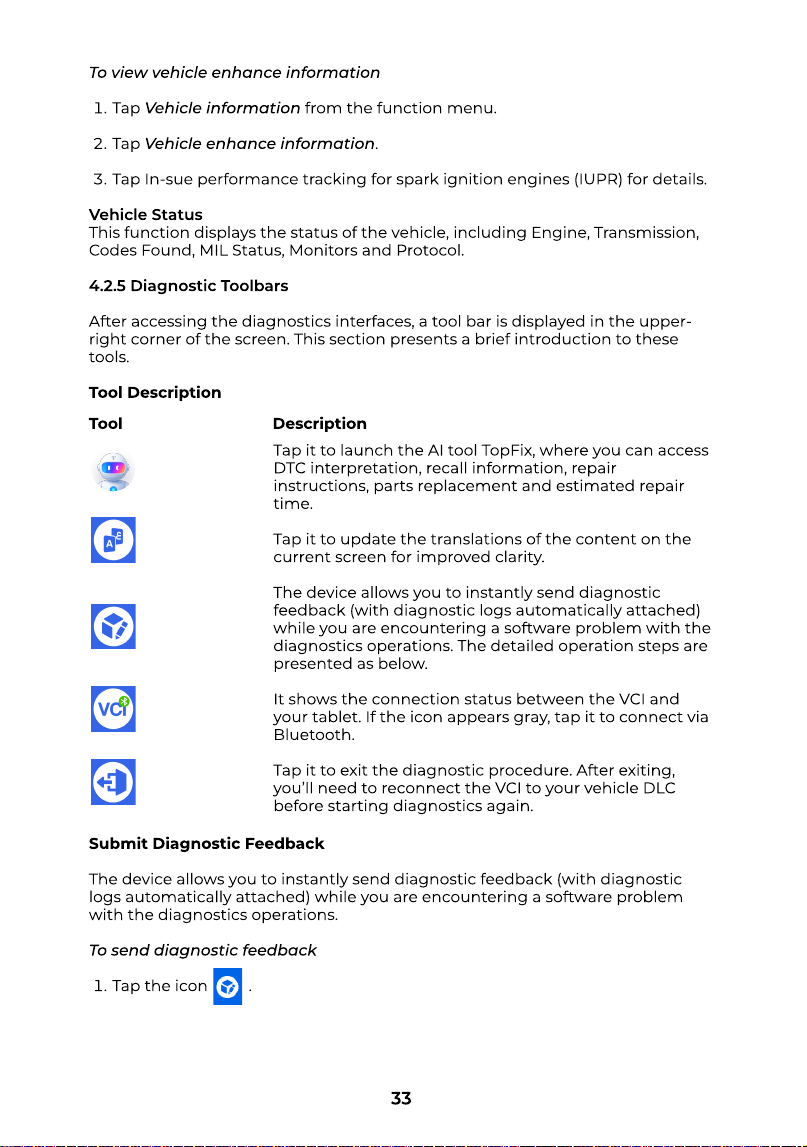
Tool Description
Submit Diagnostic Feedbac
The device allows you to instantly send diagnostic feedback (with diagnostic
logs automatically attached) while you are encountering a software problem
with the diagnostics operations
To send diagnostic feedbac
Tap the icon
Tool Description
Tap it to launch the AI tool TopFix, where you can access
DTC interpretation, recall information, repair
instructions, parts replacement and estimated repair
time
Tap it to update the translations of the content on the
current screen for improved clarity
The device allows you to instantly send diagnostic
feedback (with diagnostic logs automatically attached)
while you are encountering a software problem with the
diagnostics operations. The detailed operation steps are
presented as below
It shows the connection status between the VCI and
your tablet. If the icon appears gray, tap it to connect via
Bluetooth
Tap it to exit the diagnostic procedure. After exiting,
you’ll need to reconnect the VCI to your vehicle DLC
before starting diagnostics again.
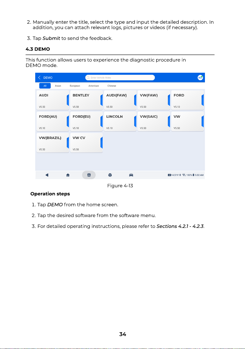
34
Figure 4-13
Manually enter the title, select the type and input the detailed description. In
addition, you can attach relevant logs, pictures or videos (if necessary)
Tap Submitto send the feedback
4.3 DEM
This function allows users to experience the diagnostic procedure in
DEMOmode.
Operation step
Tap DEMOfrom the home screen
Tap the desired software from the software menu
For detailed operating instructions, please refer to Sections 4.2.1 - 4.2.3.
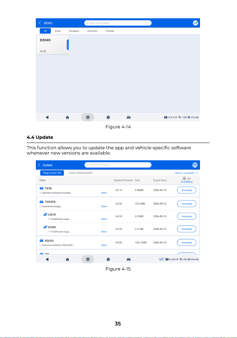
35
Figure 4-14
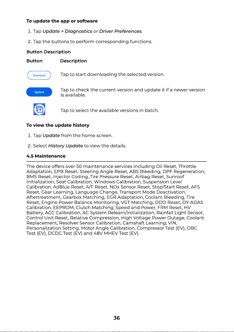
Figure 4-15
4.4 Updat
This function allows you to update the app and vehicle-specic software
whenever new versions are available.
36
To update the app or softwar
Tap Update > Diagnosticsor Driver Preferences
Tap the buttons to perform corresponding functions
Button Description
To view the update histor
Tap Updatefrom the home screen
Select History Updateto view the details
4.5 Maintenanc
The device offers over 50 maintenance services including Oil Reset, Throttle
Adaptation, EPB Reset, Steering Angle Reset, ABS Bleeding, DPF Regeneration,
BMS Reset, Injector Coding, Tire Pressure Reset, Airbag Reset, Sunroof
Initialization, Seat Calibration, Windows Calibration, Suspension Level
Calibration, AdBlue Reset, A/F Reset, NOx Sensor Reset, Stop/Start Reset, AFS
Reset, Gear Learning, Language Change, Transport Mode Deactivation,
Aftertreatment, Gearbox Matching, EGR Adaptation, Coolant Bleeding, Tire
Reset, Engine Power Balance Monitoring, VGT Matching, ODO Reset, DY-ADAS
Calibration, EEPROM, Clutch Matching, Speed and Power, FRM Reset, HV
Battery, ACC Calibration, AC System Relearn/Initialization, Rainfall Light Sensor,
Control Unit Reset, Relative Compression, High Voltage Power Outage, Coolant
Replacement, Resolver Sensor Calibration, Camshaft Learning, VIN,
Personalization Setting, Motor Angle Calibration, Compressor Test (EV), OBC
Test (EV), DCDC Test (EV) and 48V MHEV Test (EV).
Tap to start downloading the selected version
Tap to check the current version and update it if a newer version
is available
Tap to select the available versions in batch.
Button Description
37
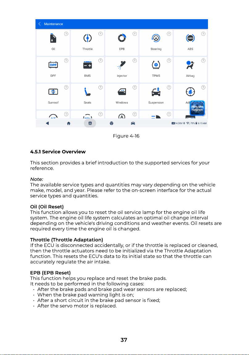
4.5.1 Service Overvie
This section provides a brief introduction to the supported services for your
reference
Note
The available service types and quantities may vary depending on the vehicle
make, model, and year. Please refer to the on-screen interface for the actual
service types and quantities
Oil (Oil Reset
This function allows you to reset the oil service lamp for the engine oil life
system. The engine oil life system calculates an optimal oil change interval
depending on the vehicle's driving conditions and weather events. Oil resets are
required every time the engine oil is changed
Throttle (Throttle Adaptation
If the ECU is disconnected accidentally, or if the throttle is replaced or cleaned,
then the throttle actuators need to be initialized via the Throttle Adaptation
function. This resets the ECU's data to its initial state so that the throttle can
accurately regulate the air intake
EPB (EPB Reset
This function helps you replace and reset the brake pads
It needs to be performed in the following cases
After the brake pads and brake pad wear sensors are replaced
When the brake pad warning light is on
After a short circuit in the brake pad sensor is xed
After the servo motor is replaced.
Figure 4-16
38
Steering (Steering Angle Reset
If the steering angle sensor is replaced, or the steering angle is inaccurate or
not centered, the steering angle reset function needs to be performed to nd
the relative zero position. With this position as a reference, the ECU can then
calculate the exact angle for left and right steering
ABS (ABS Bleeding
When the brake system is opened to replace components such as brake pump,
master cylinder, brake lines or brake uid, air may enter the system and cause a
soft brake pedal. Performing ABS Bleeding helps remove the trapped air and
restore normal brake pedal rmness
DPF (DPF Regeneration
This function is mainly used for the regeneration of diesel particulate lters. To
keep the lters performing well, it removes particles by means of combustion
and oxidation
BMS (BMS Reset
After the car battery is replaced, the battery management system (BMS) needs
to be reset. This process clears fault information (such as low battery voltage)
and allows the control unit to recognize and match the parameters of the newly
installed battery
Injector (Injector Coding
After replacing injectors, various codes need to be written to correspond to the
code of each cylinder injector. This controls the quantity of fuel injection into
each cylinder
TPMS (Tire Pressure Reset)
This function can reset the tire pressure and turn off the tire pressure fault
indicator when the car tire pressure fault indicator light is on
Airbag (Airbag Reset
This function allows you to reset the airbag data to turn off the airbag light, so
that the airbag control module can run normally
It needs to be performed in the following cases
When the airbag deploys
When the diagnostic tool reads "Crash data stored"
When the airbag light is on
When relevant DTCs cannot be cleared
Sunroof (Sunroof Initialization)
This function allows you to congure sunroof-related settings, such as disabling
the sunroof lock, enabling automatic closing when it rains, adjusting the sliding
sunroof memory, and setting the exterior temperature threshold
Seats (Seat Calibration)
This function is used to calibrate or match seats equipped with a memory
function after they are replaced or repaired
Windows (Windows Calibration)
This function performs door window calibration to reset the window position
data and restore the one-touch up/down function of the power windows.
39
Suspension (Suspension Level Calibration)
This function can adjust the vehicle body height sensor for level calibration after
replacing the vehicle height sensor or control module in the air suspension
system, or when the vehicle level is not correct
AdBlue (AdBlue Reset)
After the diesel exhaust treatment uid (car urea) is replaced or lled up, urea
reset operation is required
A/F (A/F Reset)
This function can set or learn Air/Fuel ratio parameters
NOx (NOx Sensor Reset)
This function can reset the catalytic converter learned value stored in the
engine ECU. It needs to be performed when the NOx fault is re-initialized and
the NOx catalytic converter is replaced
Stop/Start (Stop/Start Reset)
This function can enable or disable the automatic start-stop function by
conguring the hidden function in ECU (provided that the vehicle hardware
supports this function)
AFS (AFS Reset
This function enables you to initialize the adaptive headlamp system
Gear (Gear Learning)
This function can perform tooth learning for the car, to turn off the MIL. It needs
to be performed in the following cases
After the engine ECU, crankshaft position sensor, or crankshaft ywheel is
replaced
The DTC “tooth not learned” is present
Language (Language Change)
This function can change the system language of the vehicle central control
panel
Transport (Transport Mode Deactivation)
This function can deactivate the transport mode, so that the vehicle can
function normally. It needs to be performed in the following cases
When certain functions are disabled to reduce power consumption, such as
limiting the vehicle speed, disabling the door wake-up network, and
deactivating the remote control key
Aftertreatment (Aftertreatment
After prolonged use, the particulate lter may cause increased fuel
consumption and reduced engine output, requiring replacement or
regeneration of the GPF
Gearbox (Gearbox Matching
This function helps complete the gearbox self-learning to improve gear shifting
quality. It needs to be performed when the gearbox is disassembled or repaired
(after some of the car battery is powered off), which leads to shift delay or
impact problem.
40
EGR (EGR Adaptation
This function allows the ECU to learn the EGR (Exhaust Gas Recirculation) valve
after the valve has been cleaned or replaced
Water Pump (Coolant Bleeding
This function activates the electronic water pump to circulate coolant before
venting the cooling syste
Tire (Tire Reset)
This function can set the parameters of the size of the modied or replaced tire
Power Balance (Engine Power Balance Monitoring
During the power stroke of each cylinder, the power balance function monitors
crankshaft acceleration to determine the relative power output of each cylinder
VGT (VGT Matching
VGT Matching refers to the learning process after replacement of turbocharger
components or the reset of turbocharger learning values
ODO (ODO Reset
This function can copy, write, or correct the value of kilometers in the chip of
odometer, so that the odometer shows the actual mileage. It needs to be
performed in the following cases
When the mileage is not correct due to the damaged vehicle speed sensor
or the odometer failure
DY-ADAS(DY-ADAS Calibration
Dynamic ADAS Calibration allows the vehicle to automatically perform
calibration and learning of ADAS sensors, such as radar, LiDAR, mono or stereo
cameras, and GNSS modules, after replacement, without requiring special tools
or targets
EEPROM (EEPROM
The EEPROM adapter is mainly used in vehicle anti-theft systems for models
that require chip removal. Users can remove the security chip from control
units such as the immobilizer box or instrument cluster to read the stored code
information
Clutch (Clutch Matching
Clutch Matching calibrates the clutch system after replacing the clutch disc or
related components to ensure smooth gear shifting
Speed & PTO (Speed and Power
Speed & PTO allows setting the vehicle’s top speed or engine output
FRM (FRM Reset
FRM Reset allows clearing short-circuit faults in the lighting system
HV Battery (HV Battery
The HV Battery function is designed for diagnostics and state monitoring of the
high-voltage battery
ACC (ACC Calibration
ACC Calibration is performed to match the adaptive cruise control module after
it has been replaced or repaired.
41
A/C (AC System Relearn/Initialization
If the ECU or actuator of the vehicle air conditioner is replaced, or the memory
of the ECU memory is lost, air conditioner initialization learning is needed
Rain/Light (Rainfall Light Sensor
The rain and light sensors automatically adjust the wiper speed and headlight
brightness based on rainfall and ambient light conditions. This function also
allows parameter adjustments
ECU Reset (Control Unit Reset
After performing coding functions on certain systems, a Control Unit Reset
must be carried out
Relative Compression (Relative Compression
The Relative Compression function detects compression issues by comparing
the starter speed of each cylinder with the overall average
HVPO (High Voltage Power Outage
For safety reasons related to the power and drive systems in EVs/HEVs, a high-
voltage power shutdown must be performed before servicing certain electrical
components
Coolant Replacement (Coolant Replacement
Coolant performance deteriorates during normal use and must be replaced at
regular intervals. In this case, Coolant Replacement needs to be performed
Resolver Sensor (Resolver Sensor Calibration
Resolver Sensor Calibration calibrates a resolver, a position sensor that detects
the rotor angle and supplies essential data for motor control
Camshaft (Camshaft Learning
Camshaft Learning refers to the calibration process of the camshaft position.
This process typically involves precise adjustment to ensure accuracy and
stability during engine operation
VIN (VIN
VIN refers to gateway module data calibration. After replacing the gateway
control unit, the VIN may be inconsistent and requires updating
Customize (Personalization Setting
For vehicles with hidden features, this function allows you to recongure and
enable these features after the initial setup
Motor Angle (Motor Angle Calibration
Motor Angle Calibration adjusts the rotor position sensor to align detected rotor
angles with the actual magnetic eld position
Compressor Test (EV
Compressor Test evaluates the operation and efciency of the compressor in
electric vehicles
OBC Test (EV
OBC Test evaluates the charging performance of the electric vehicle’s on-board
charger (OBC).
42
DCDC Test (EV
DCDC Test evaluates the operation of the DC-DC converter, converting high-
voltage input to low-voltage output
48V MHEV Test (EV
48V MHEV Test evaluates the performance and power output of 48V mild
hybrid system components
4.5.2 Perform Maintenance Service
Tap Maintenancefrom the home screen to display the function menu
Select the desired service
Choose the vehicle-specic diagnostic software
Identify the vehicle using the VIN or make. (For details on identication, see
the Section 4.2.1.) Once the vehicle is identied, the app automatically takes
you to the function display screen
Follow the on-screen instructions to perform the service reset
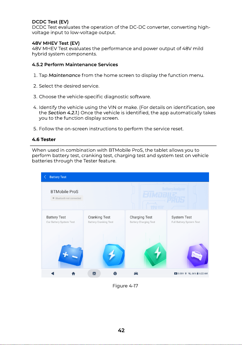
4.6 Teste
When used in combination with BTMobile ProS, the tablet allows you to
perform battery test, cranking test, charging test and system test on vehicle
batteries through the Testerfeature.
Figure 4-17
43
Note
The BTMobile ProS is sold separately
Before performing this function, a Bluetooth connnection between the tablet
and BTMobile ProS is required
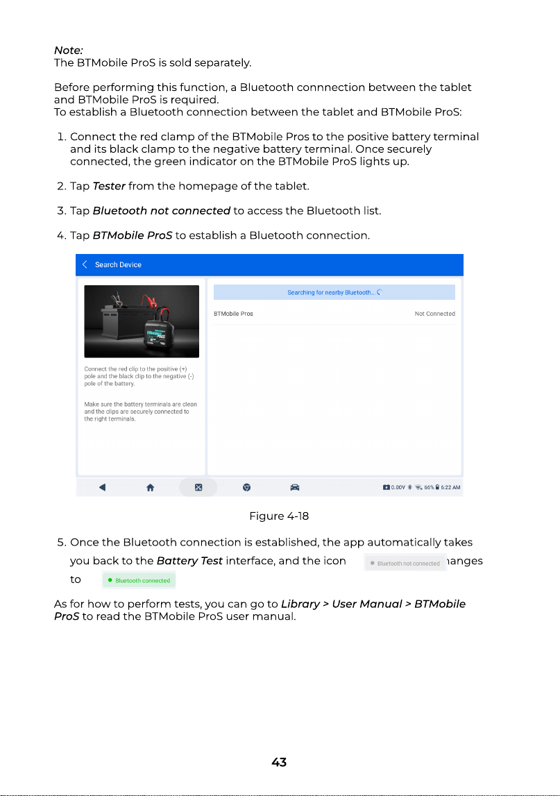
To establish a Bluetooth connection between the tablet and BTMobile ProS
Connect the red clamp of the BTMobile Pros to the positive battery terminal
and its black clamp to the negative battery terminal. Once securely
connected, the green indicator on the BTMobile ProS lights up
Tap Testerfrom the homepage of the tablet
Tap Bluetooth not connectedto access the Bluetooth list
Tap BTMobile ProSto establish a Bluetooth connection.
Once the Bluetooth connection is established, the app automatically takes
you back to the Battery Testinterface, and the icon changes
to
As for how to perform tests, you can go to Library > User Manual > BTMobile
ProSto read the BTMobile ProS user manual.
Figure 4-18
44
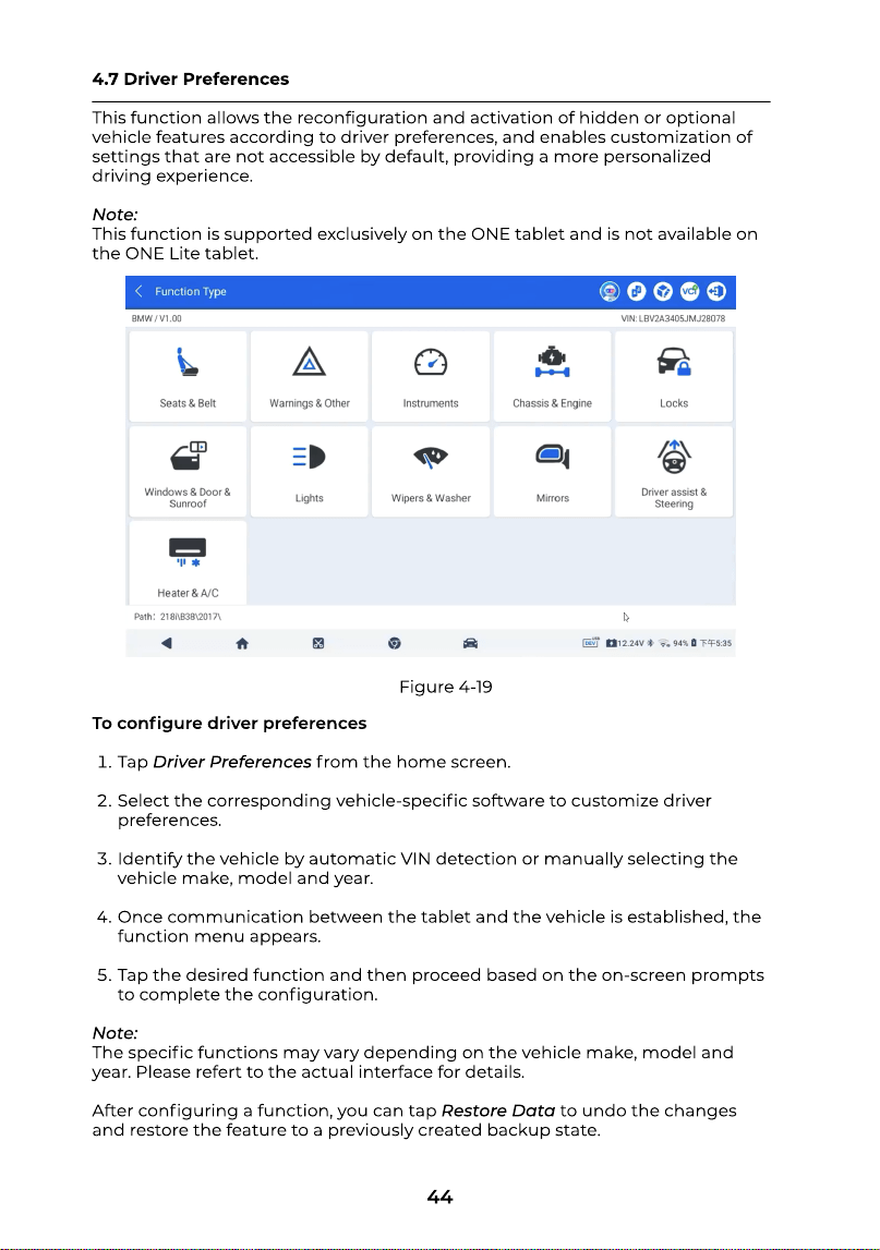
4.7 Driver Preference
This function allows the reconguration and activation of hidden or optional
vehicle features according to driver preferences, and enables customization of
settings that are not accessible by default, providing a more personalized
driving experience
Note
This function is supported exclusively on the ONE tablet and is not available on
the ONE Lite tablet.
To congure driver preference
Tap Driver Preferencesfrom the home screen
Select the corresponding vehicle-specic software to customize driver
preferences
Identify the vehicle by automatic VIN detection or manually selecting the
vehicle make, model and year
Once communication between the tablet and the vehicle is established, the
function menu appears
Tap the desired function and then proceed based on the on-screen prompts
to complete the conguration
Note
The specic functions may vary depending on the vehicle make, model and
year. Please refert to the actual interface for details
After conguring a function, you can tap Restore Datato undo the changes
and restore the feature to a previously created backup state.
Figure 4-19
45
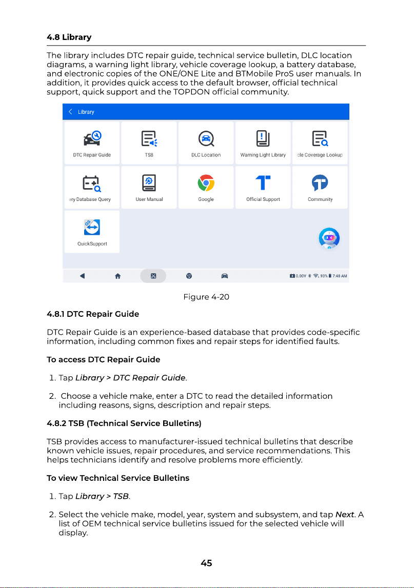
4.8 Librar
The library includes DTC repair guide, technical service bulletin, DLC location
diagrams, a warning light library, vehicle coverage lookup, a battery database,
and electronic copies of the ONE/ONE Lite and BTMobile ProS user manuals. In
addition, it provides quick access to the default browser, ofcial technical
support, quick support and the TOPDON ofcial community.
4.8.1 DTC Repair Guid
DTC Repair Guide is an experience-based database that provides code-specic
information, including common xes and repair steps for identied faults
To access DTC Repair Guid
Tap Library > DTC Repair Guide
Choose a vehicle make, enter a DTC to read the detailed information
including reasons, signs, description and repair steps
4.8.2 TSB (Technical Service Bulletins
TSB provides access to manufacturer-issued technical bulletins that describe
known vehicle issues, repair procedures, and service recommendations. This
helps technicians identify and resolve problems more efciently
To view Technical Service Bulletin
Tap Library > TSB
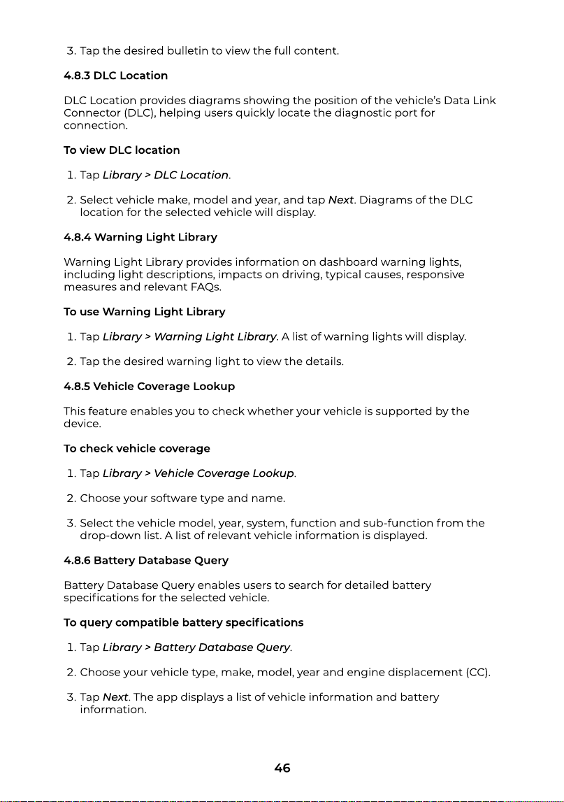
Select the vehicle make, model, year, system and subsystem, and tap Next. A
list of OEM technical service bulletins issued for the selected vehicle will
display.
Figure 4-20
46
Tap the desired bulletin to view the full content
4.8.3 DLC Locatio
DLC Location provides diagrams showing the position of the vehicle’s Data Link
Connector (DLC), helping users quickly locate the diagnostic port for
connection
To view DLC locatio
Tap Library > DLC Location
Select vehicle make, model and year, and tap Next. Diagrams of the DLC
location for the selected vehicle will display
4.8.4 Warning Light Librar
Warning Light Library provides information on dashboard warning lights,
including light descriptions, impacts on driving, typical causes, responsive
measures and relevant FAQs
To use Warning Light Librar
Tap Library > Warning Light Library. A list of warning lights will display
Tap the desired warning light to view the details
4.8.5 Vehicle Coverage Looku
This feature enables you to check whether your vehicle is supported by the
device
To check vehicle coverag
Tap Library > Vehicle Coverage Lookup
Choose your software type and name
Select the vehicle model, year, system, function and sub-function from the
drop-down list. A list of relevant vehicle information is displayed
4.8.6 Battery Database Quer
Battery Database Query enables users to search for detailed battery
specications for the selected vehicle
To query compatible battery specication
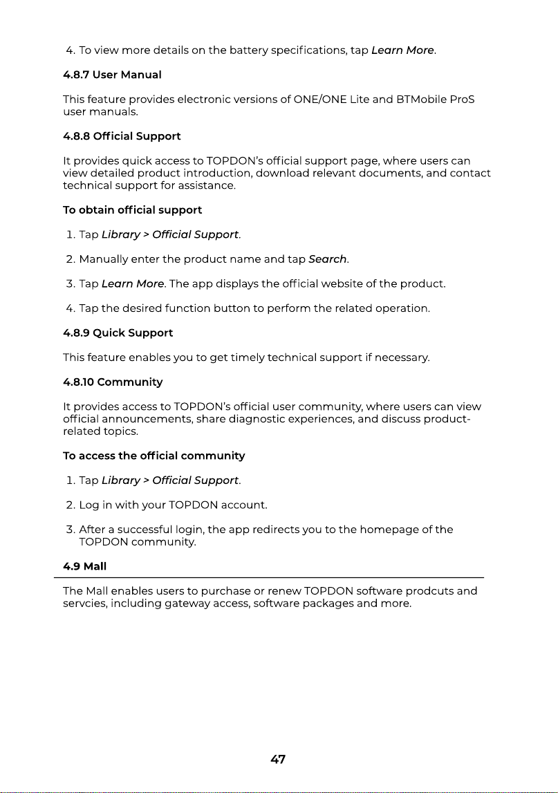
Tap Library > Battery Database Query
Choose your vehicle type, make, model, year and engine displacement (CC)
Tap Next. The app displays a list of vehicle information and battery
information
47
To view more details on the battery specications, tap Learn More
4.8.7 User Manua
This feature provides electronic versions of ONE/ONE Lite and BTMobile ProS
user manuals
4.8.8 Ofcial Suppor
It provides quick access to TOPDON’s ofcial support page, where users can
view detailed product introduction, download relevant documents, and contact
technical support for assistance
To obtain ofcial suppor
Tap Library > Ofcial Support
Manually enter the product name and tap Search
Tap Learn More. The app displays the ofcial website of the product
Tap the desired function button to perform the related operation
4.8.9 Quick Suppor
This feature enables you to get timely technical support if necessary
4.8.10 Communit
It provides access to TOPDON’s ofcial user community, where users can view
ofcial announcements, share diagnostic experiences, and discuss product-
related topics
To access the ofcial communit
Tap Library > Ofcial Support
Log in with your TOPDON account
After a successful login, the app redirects you to the homepage of the
TOPDON community
4.9 Mal
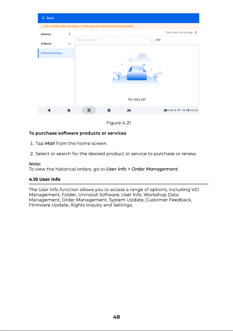
The Mall enables users to purchase or renew TOPDON software prodcuts and
servcies, including gateway access, software packages and more.
48
To purchase software products or service
Tap Mallfrom the home screen
Select or search for the desired product or service to purchase or renew
Note
To view the historical orders, go to User Info > Order Management
4.10 User Inf
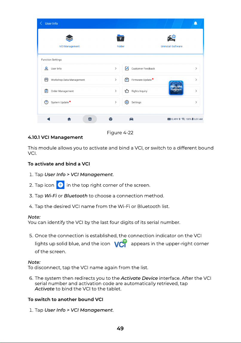
The User Infofunction allows you to access a range of options, including VCI
Management, Folder, Uninstall Software, User Info, Workshop Data
Management, Order Management, System Update, Customer Feedback,
Firmware Update, Rights Inquiry and Settings.
Figure 4-21
49
4.10.1 VCI Managemen
This module allows you to activate and bind a VCI, or switch to a different bound
VCI
To activate and bind a VC
Tap User Info > VCI Management
Tap icon in the top right corner of the screen
Tap Wi-Fior Bluetoothto choose a connection method
Tap the desired VCI name from the Wi-Fi or Bluetooth list
Note
You can identify the VCI by the last four digits of its serial number
Once the connection is established, the connection indicator on the VCI
lights up solid blue, and the icon appears in the upper-right corner
of the screen
Note
To disconnect, tap the VCI name again from the list
The system then redirects you to the Activate Deviceinterface. After the VCI
serial number and activation code are automatically retrieved, tap
Activateto bind the VCI to the tablet
To switch to another bound VC
Tap User Info > VCI Management.
Figure 4-22
50
Tap the desired VCI from the list. The system will automatically complete the
switch
4.10.2 Folde
This feature contains diagnostic reports, replay data, battery test reports,
screenshots, screen recordings, photos and an access to the le manager
To view diagnostic report
Tap User Info > Folder > Diagnostic Report
Filter the diagnostic report via All/System Report/Fault Code Report/Data
Stream Report
Tap the desired report to view details
To view replay dat
Tap User Info > Folder > Replay Data
Tap the desired data stream recordings to view details
Note
To delete the recordings, tap the icon , select the desired replay data and
tap Delete
To view battery test report
Tap User Info > Folder > Battery Test Report
Filter the diagnostic report via All/Battery Test/Charging Test/Cranking Test/
System Test
Tap the desired report to view details
To view saved pictures and video
Tap User Info > Folder > Gallery
Filter the diagnostic report via ALL/TAKE PHOTO/SCREENSHOTS/SCREEN
REC
Tap the desired picture or video to view details
To access le managemen
Tap User Info > Folder > File Manager
Tap the desired option to view details
51
4.10.3 Uninstall Softwar
This function allows you to remove previously installed diagnostic software
To uninstall vehicle-specic diagnostics softwar
Tap User Info > Uninstall Software
Choose the corresponding VCI serial number and function type from the
drop-down list or manually enter the vehicle make to search
Choose the desired software from the list and tap Delete
4.10.4 User Inf
This function allows you to view your ID and email address, update avatar and
nickname, enable or disable two-factor authentication, change password,
delete account and log out
Warning
Account deletion is irreversible and cannot be undone. Once the account is
deleted, all data stored in the account will be cleared
4.10.5 Workshop Data Managemen
This function enables you to save and edit the information of workshops,
technicians and customers
4.10.6 Order Managemen
This function allows you to view order details and delete orders
4.10.7 System Updat
This function enables users to update the software if a new version is available
Note
The system cannot be updated when the battery is low
4.10.8 Customer Feedbac
This feature enables users to submit feedback on our products and services
To submit feedbac
Tap User Info > Customer Feedback
Manually input the title, choose the feedback type and enter the problem
description. In addition, you can attach relevant logs and pictures or videos if
necessary
Tap Submit.
52
4.10.9 Firmware Updat
This function helps you to update the rmware if a new version is available
4.10.10 Rights Inquir
Rights Inquiry provides services for checking SN validity, querying remaining
gateway access, and viewing other user rights
4.10.11 Setting
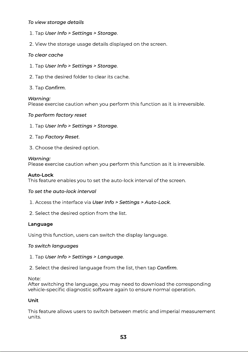
This feature allows you to access system settings, view storage details, set the
auto-lock interval, change languages and units, switch device modes, check
product and service information, and log out.
System Setting
It includes options for conguring Wi-Fi, date and time, battery, and security
settings
To access system setting
Tap User Info > Settings > System Settings
Tap the desired option to congure the corresponding settings
Storag
This feature allows you to view storage details, clear cache and perform factory
reset.
Figure 4-23
53
To view storage detail
Tap User Info > Settings > Storage
View the storage usage details displayed on the screen
To clear cach
Tap User Info > Settings > Storage
Tap the desired folder to clear its cache
Tap Conrm
Warning
Please exercise caution when you perform this function as it is irreversible
To perform factory rese
Tap User Info > Settings > Storage
Tap Factory Reset
Choose the desired option
Warning
Please exercise caution when you perform this function as it is irreversible
Auto-Loc
This feature enables you to set the auto-lock interval of the screen
To set the auto-lock interva
Access the interface via User Info > Settings > Auto-Lock
Select the desired option from the list
Languag
Using this function, users can switch the display language
To switch language
Tap User Info > Settings > Language
Select the desired language from the list, then tap Conrm
Note
After switching the language, you may need to download the corresponding
vehicle-specic diagnostic software again to ensure normal operation
Uni
This feature allows users to switch between metric and imperial measurement
units.
54
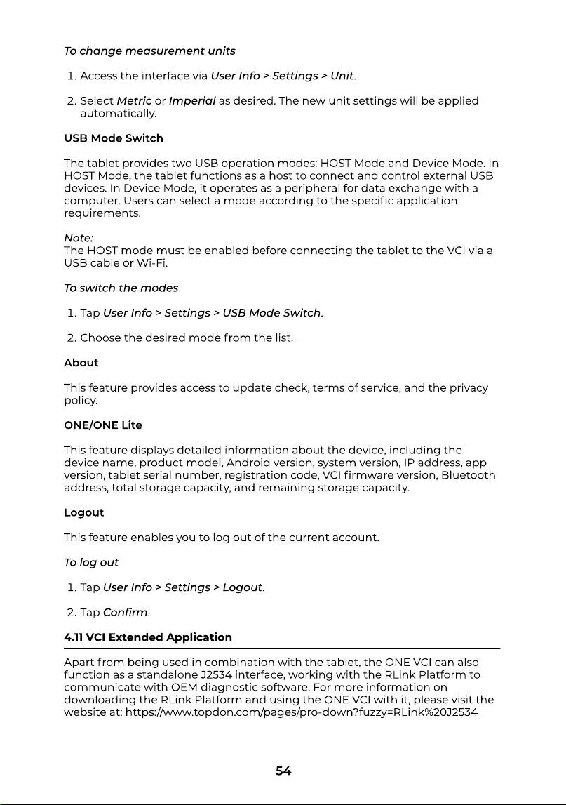
To change measurement unit
Access the interface via User Info > Settings > Unit
Select Metricor Imperialas desired. The new unit settings will be applied
automatically
USB Mode Switc
The tablet provides two USB operation modes: HOST Mode and Device Mode. In
HOST Mode, the tablet functions as a host to connect and control external USB
devices. In Device Mode, it operates as a peripheral for data exchange with a
computer. Users can select a mode according to the specic application
requirements
Note
The HOST mode must be enabled before connecting the tablet to the VCI via a
USB cable or Wi-Fi
To switch the mode
Tap User Info > Settings > USB Mode Switch
Choose the desired mode from the list
Abou
This feature provides access to update check, terms of service, and the privacy
policy
ONE/ONE Lit
This feature displays detailed information about the device, including the
device name, product model, Android version, system version, IP address, app
version, tablet serial number, registration code, VCI rmware version, Bluetooth
address, total storage capacity, and remaining storage capacity
Logou
This feature enables you to log out of the current account
To log ou
Tap User Info > Settings > Logout
Tap Conrm
4.11 VCI Extended Applicatio
Apart from being used in combination with the tablet, the ONE VCI can also
function as a standalone J2534 interface, working with the RLink Platform to
communicate with OEM diagnostic software. For more information on
downloading the RLink Platform and using the ONE VCI with it, please visit the
website at: https://www.topdon.com/pages/pro-down?fuzzy=RLink%20J2534
55
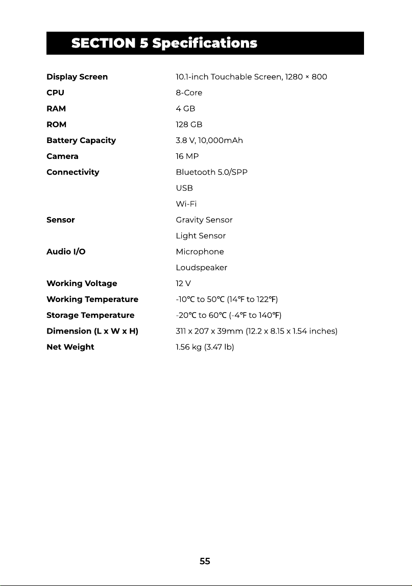
SECTION 5 SPECIFICATIONSSECTION 5 Specications
Display Scree
CP
RA
RO
Battery Capacit
Camer
Connectivit
Senso
Audio I/
Working Voltag
Working Temperatur
Storage Temperatur
Dimension (L x W x H
Net Weight
10.1-inch Touchable Screen, 1280 × 80
8-Cor
4 G
128 G
3.8 V, 10,000mA
16 M
Bluetooth 5.0/SP
US
Wi-F
Gravity Senso
Light Senso
Microphon
Loudspeake
12
-10℃ to 50℃ (14℉ to 122℉
-20℃ to 60℃ (-4℉ to 140℉
311 x 207 x 39mm (12.2 x 8.15 x 1.54 inches
1.56 kg (3.47 lb)
56
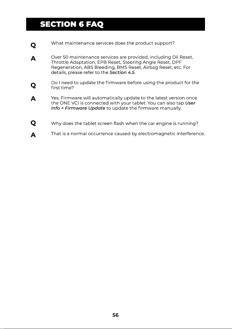
SECTION 5 SPECIFICATIONSSECTION 6 FAQ
A
What maintenance services does the product support
Over 50 maintenance services are provided, including Oil Reset,
Throttle Adaptation, EPB Reset, Steering Angle Reset, DPF
Regeneration, ABS Bleeding, BMS Reset, Airbag Reset, etc. For
details, please refer to the Section 4.5
Do I need to update the rmware before using the product for the
rst time
Yes. Firmware will automatically update to the latest version once
the ONE VCI is connected with yourtablet. You can also tap User
Info > Firmware Updateto update the rmware manually
Why does the tablet screen ash when the car engine is running
That is a normal occurrence caused by electromagnetic interference.
57
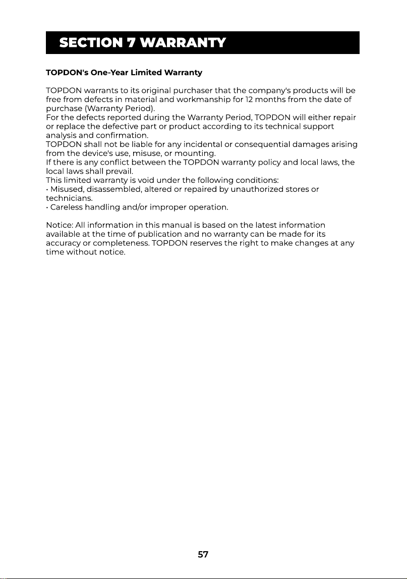
TOPDON's One-Year Limited Warrant
TOPDON warrants to its original purchaser that the company's products will be
free from defects in material and workmanship for 12 months from the date of
purchase (Warranty Period).
For the defects reported during the Warranty Period, TOPDON will either repair
or replace the defective part or product according to its technical support
analysis and conrmation
TOPDON shall not be liable for any incidental or consequential damages arising
from the device's use, misuse, or mounting.
If there is any conict between the TOPDON warranty policy and local laws, the
local laws shall prevail
This limited warranty is void under the following conditions
• Misused, disassembled, altered or repaired by unauthorized stores or
technicians
• Careless handling and/or improper operation
Notice: All information in this manual is based on the latest information
available at the time of publication and no warranty can be made for its
accuracy or completeness. TOPDON reserves the right to make changes at any
time without notice.
SECTION 7 WARRANTY
58
Compliance Information
Regulatory Complianc
Table
FCC ID: 2AVYW-TDON
IC: 32511-TDON
HVIN: ONE/ONE Lit
VC
FCC ID: 2AVYW-TDONEVC
IC: 32511-TDONEVC
HVIN: ONE VC
FCC & ISED Statemen
This device complies with Part 15 of the FCC Rules [and contains license-exempt
transmitter(s)/receiver(s) that comply with Innovation, Science and Economic
Development Canada’s licence-exempt RSS standard(s)]
Operation is subject to the following two conditions
(1) This device may not cause harmful interference, an
(2) This device must accept any interference received, including interference
that may cause undesired operation of the device
L’émetteur/récepteur exempt de licence contenu dans le présent appareil est
conforme aux CNR d’Innovation, Sciences et Développement économique
Canada applicables aux appareils radio exempts de licence
L'exploitation est autorisée aux deux conditions suivantes
(1) l'appareil ne doit pas produire de brouillage, e
(2) l'appareil doit accepter tout brouillage radioélectrique subi, même si le
brouillage est susceptible d'en compromettre le fonctionnement
Changes or modications not expressly approved by the party responsible for
compliance could void your authority to operate the equipment
FCC VO
This equipment has been tested and found to comply with the limits for a Class
B digital device, pursuant to Part 15 of the FCC Rules. These limits are designed
to provide reasonable protection against harmful interference in a residential
installation. This equipment generates, uses and can radiate radio frequency
energy and, if not installed and used in accordance with the instructions, may
cause harmful interference to radio communications. However, there is no
guarantee that interference will not occur in a particular installation. If this
equipment does cause harmful interference to radio or television reception,
which can be determined by turning the equipment off and on, the user is
encouraged to try to correct the interference by one or more of the following
measures
-- Reorient or relocate the receiving antenna
-- Increase the separation between the equipment and receiver
-- Connect the equipment into an outlet on a circuit different from that to
which the receiver is connected
-- Consult the dealer or an experienced radio/TV technician for help
In case this equipment has to subject to FCC/IC SAR (Specic Absorption Rate)
exposure test, this equipment is designed to meet the requirements for
exposure to radio waves established by the FCC and ISED. These requirements
set a SAR limit of 1.6 W/kg averaged over one gram of tissue. The highest SAR
value reported under this standard during product certication for use when
properly worn on the body is within regulatory limits
59
FCC Cautio
The device for operation in the band 5150-5250 MHz is only for indoor use to
reduce the potential for harmful interference to co-channel mobile satellite
systems
IC Cautio
1.The device for operation in the band 5150-5250 MHz is only for indoor use to
reduce the potential for harmful interference to co-channel mobile satellite
systems
2.For devices with detachable antenna(s), the maximum antenna gain
permitted for devices in the band 5725-5850 MHz shall be such that the
equipment still complies with the e.i.r.p. limits specied for point-to-point and
non-point-to-point operation as appropriate
3.les dispositifs fonctionnant dans la bande 5150-5250 MHz sont réservés
uniquement pour une utilisation à l’intérieur an de réduire les risques de
brouillage préjudiciable aux systèmes de satellites mobiles utilisant les mêmes
canaux
4.le gain maximal d’antenne permis (pour les dispositifs utilisant la bande
5725-5850 MHz) doit se conformer à la limite de p.i.r.e. spéciée pour
l’exploitation point à point et non point à point, selon le cas.