F6391110V
READ AND SAVE THESE INSTRUCTIONS
INSTALLATION MANUAL
English
WARNING: To reduce the risk of personal injury,
do not bend the blade brackets (also referred to as
flanges) during assembly or after installation. Do not
insert objects in the path of the blades.
WARNING: To reduce the risk or fire or electric
shock, do not use this fan with any solid-state
speed control device.
WARNING: To avoid possible electric shock,
turn the electricity off at the main fuse box before
wiring. If you feel you do not have enough electrical
wiring knowledge or experience, contact a licensed
electrician.
WARNING: Electrical diagrams are for reference
only. Optional use of any light kit shall be UL-listed
and marked suitable for use with this fan.
WARNING: To reduce the risk or fire, electric shock,
or personal injury, mount to outlet box marked”
Acceptable for fan support of 35 lbs.(15.9 kg) or
less“ and use the screws provided with the outlet
box.
WARNING: Remove the rubber motor stops on
the bottom of the fan before installing the blades
or testing the motor.
Safety Information
To reduce the risk of electric shock, the electricity
has been turned off at the circuit breaker or fuse
box before begin.
All wiring must be in accordance with the National Electrical
Code NASI/NFPA 70-1999 and local electrical codes.
Electrical installation should be performed by a qualified
licensed electriccian.
The outlet box and support structure must be securely
mounted and capable of reliably supporting
35lbs(15.9kg). Use only UL listed outlet boxes marked
“Acceptable for Fan Support of 35lbs(15.9kg) or less.”
The fan must be mounted with a minimum of 7 ft. (2.1m)
clearance from the trailing edge of the blades to the floor.
Do not operate the reversing switch while the fan blades
are in motion. You must turn the fan off and stop the
blades before you reverse the blade direction.
Do not place objects in the path of the blades.
To avoid personal injury or damage to the fan and
other items, please be careful when working around
or cleaning the fan.
Electrical diagrams are for reference only. Light kits that
are not packed with the fan must be UL-listed and marked
suitable for use with the model fan you are installing.
Switches must be UL General Use Switches. Refer to the
instructions packaged with the light kits and switches for
proper assembly.
After making electrical connections, spliced conductors
should be turned upward and pushed carefully up into
the outlet box. The wires should be spread apart with the
grounded conductor and the equipment-grounding
conductor on one side of the outlet box.
All set screws must be checked and retightened where
necessary before installation.
1.
2.
3.
4.
5.
6.
7.
8.
9.
10.
Installation & Operating Instructions for the
Parrotuncle Owner's Installation, Manual
WARNING: SHUT POWER OFF AT FUSE OR CIRCUIT BERAKER
F6391110V
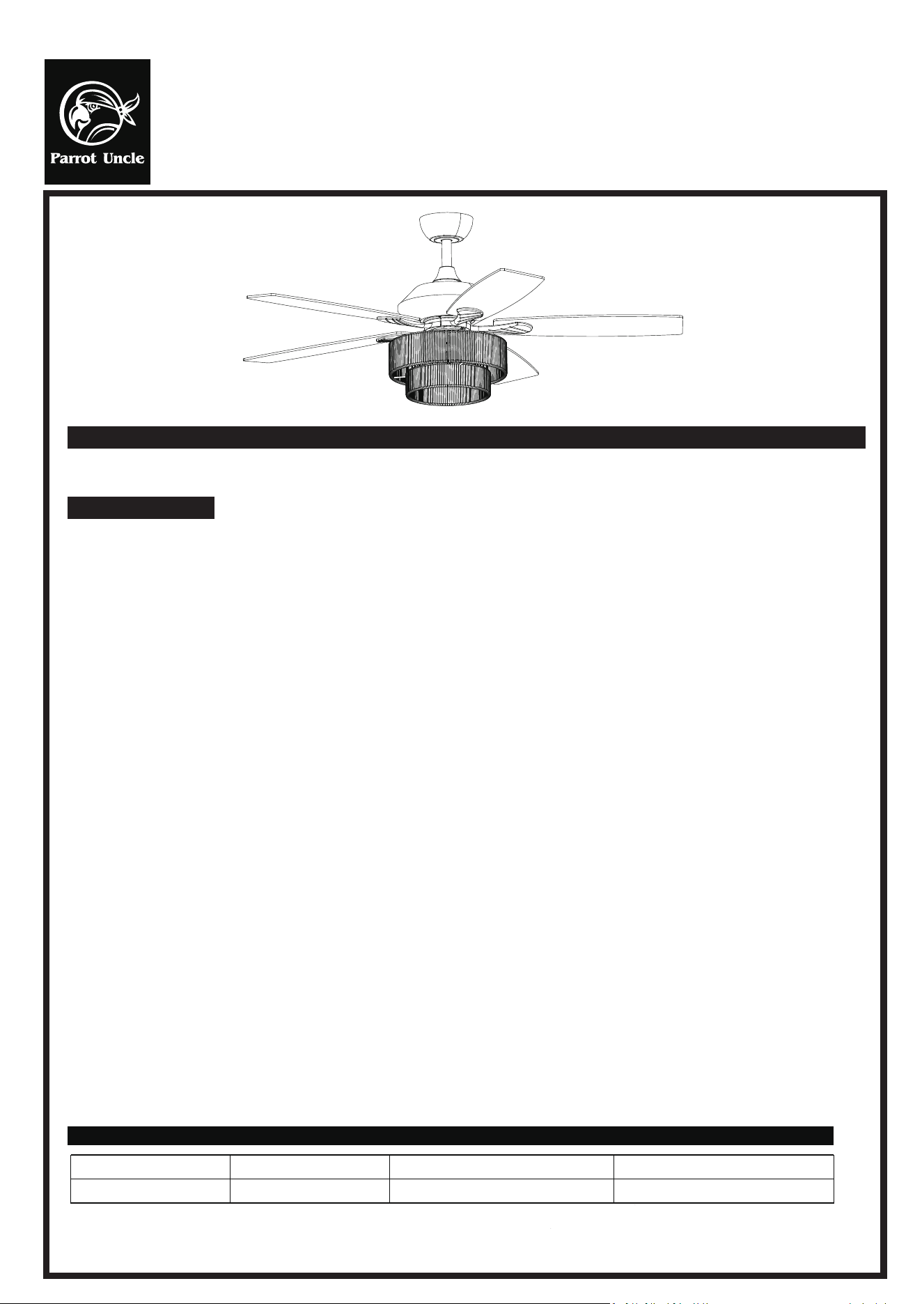
Thank you for purchasing this quality product. To ensure correct function and safety, please read and save all instructions before using the
product.
1. To avoid possible electric shock, turn off the electricity at the main fuse box or circuit panel before you begin the fan installation or before servicing the fan or
installing accessories.
2. Read all instructions and safety information carefully before installing your fan and save these instructions.
3. Make sure all electrical connections comply with local codes or ordinances and the National Electrical Code. If you are unfamiliar with electric wiring, please
use a qualified and licensed electrician.
4. Make sure you have a location selected for your fan that allow clear space for the blades to rotate, and at least seven(7) feet of clearance between the floor and
the fan blade tips. The fan should be mounted at least thirty (30) inches from walls or other up right structures.
5.WARNING: The outlet box and ceiling support joist used must be securely mounted, and capable of supporting at least 100 pounds. To reduce the risk of fire,
electric shock or personal injury, mount to the outlet box marked acceptable for fan supported and use mounting screws provided with the outlet box. The box must
be supported directly by the building structure.
6. WARNING: To reduce the risk of fire, electric shock or personal injuy, mount to outlet box marked "acceptable for fan support" and use mounting screws
provided with the outlet box most outlet boxes commonly used for the support of lighting fixtures are not acceptable for fan support and may need to be replaced.
Consulta qualified electrician if in doubt.
7. Electrical diagrams are for reference only. Light kits that are not packed with the fan must UL listed and marked suitable for use with the model fan you are
installing. Switches must be UL. general use switches. Refer to the instructions packaged with the light kits and switches for proper assembly.
8. After installation is complete, check that all connections are absolutely secure.
9. After making electrical connections, spliced conductors should be turned upward and pushed carefully up into outlet box. The wires should be spread apart with
the grounded conductor and the equipment-grounding conductor on one side of the outlet box.
10. WARNING: To reduce the risk of electrical shock and fire, do not use this fan with any solid-state fan speed control device, or rheostat.
11. Do not separate the reverse switch until the fan has come to a complete stop.
12. Do not insert anything into the fan blades while they are rotating.
13. WARNING: To reduce the risk of personal injury, do not bend the blade brackets (also referred to as "flanges") during assembly or after installation.
Do not insert objects in the path of the blades.
14. To avoid personal injury or damage to the fan and other items, be cautious when working around or cleaning the fan.
15. Do not use water or detergent when cleaning the fan or fan bades. A dry dust cloth or lightly dampened cloth will be suitable for most cleaning.
NOTE: The important safety precautions and instructions appearing in the manual are not meant to cover all possible conditions and situations that may occur.
It must be understand that common sense and caution are necessary factors in the installation and operation and operation of this fan.
NOTE: This productis not intended for use by persons (including children) with reduced physical, sensory or mental capabilities are different or are impaired, or
lack of experience or knowledge, unless such persons are supervised or trained to operate the appliance by a person responsible for their safety.
NOTE: Children should be supervised to ensure that they do not use appliances as a toy.
SAFETY TIP
TECHNICAL INFORMATION
SKU# Rated Voltage
F6391110V
110-120 VAC
28W±5W 2*E12 Bulb MAX.25W (not included)
Rated Power (motor) Light
Installation & Operating Instructions for the
Parrotuncle Owner's Installation, Manual
WARNING: SHUT POWER OFF AT FUSE OR CIRCUIT BERAKER
F6391110V
THANK YOU FOR YOUR PURCHASE
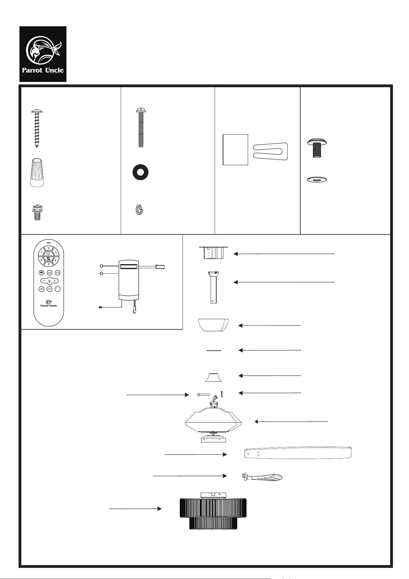
Mounting screws
(2PCS)
Washer (2PCS)
Spring washer
(2PCS)
Wood screws
(4PCS)
Plastic wire nut
(4PCS)
Blade bracket screws
(1PC)
Balanced parts package
(1PC)
Blade screw
(16PCS)
Blade washer
(16PCS)
Remote control (1PC)
PIs check whether above accessories are completed or not? Yes, and install.
Installation & Operating Instructions for the
Parrotuncle Owner's Installation, Manual
WARNING: SHUT POWER OFF AT FUSE OR CIRCUIT BERAKER
F6391110V
Neutral Wire N
Neutral Wire N
Live Wire L
AC IN Black L
AC IN White N
Live Wire for Motor
Antenna
Slide-on mounting bracket
6" Ball/downrod assembly
10" Ball/downrod assembly(standby)
Canopy
Canopy cover
Coupling cover
"R" Locking Pin
Fan-motor assembly
Hanging Pin
Blade (5PCS)
Light kit
Blade bracket (5PCS)
8H
Installation & Operating Instructions for the
Parrotuncle Owner's Installation, Manual
WARNING: SHUT POWER OFF AT FUSE OR CIRCUIT BERAKER
F6391110V
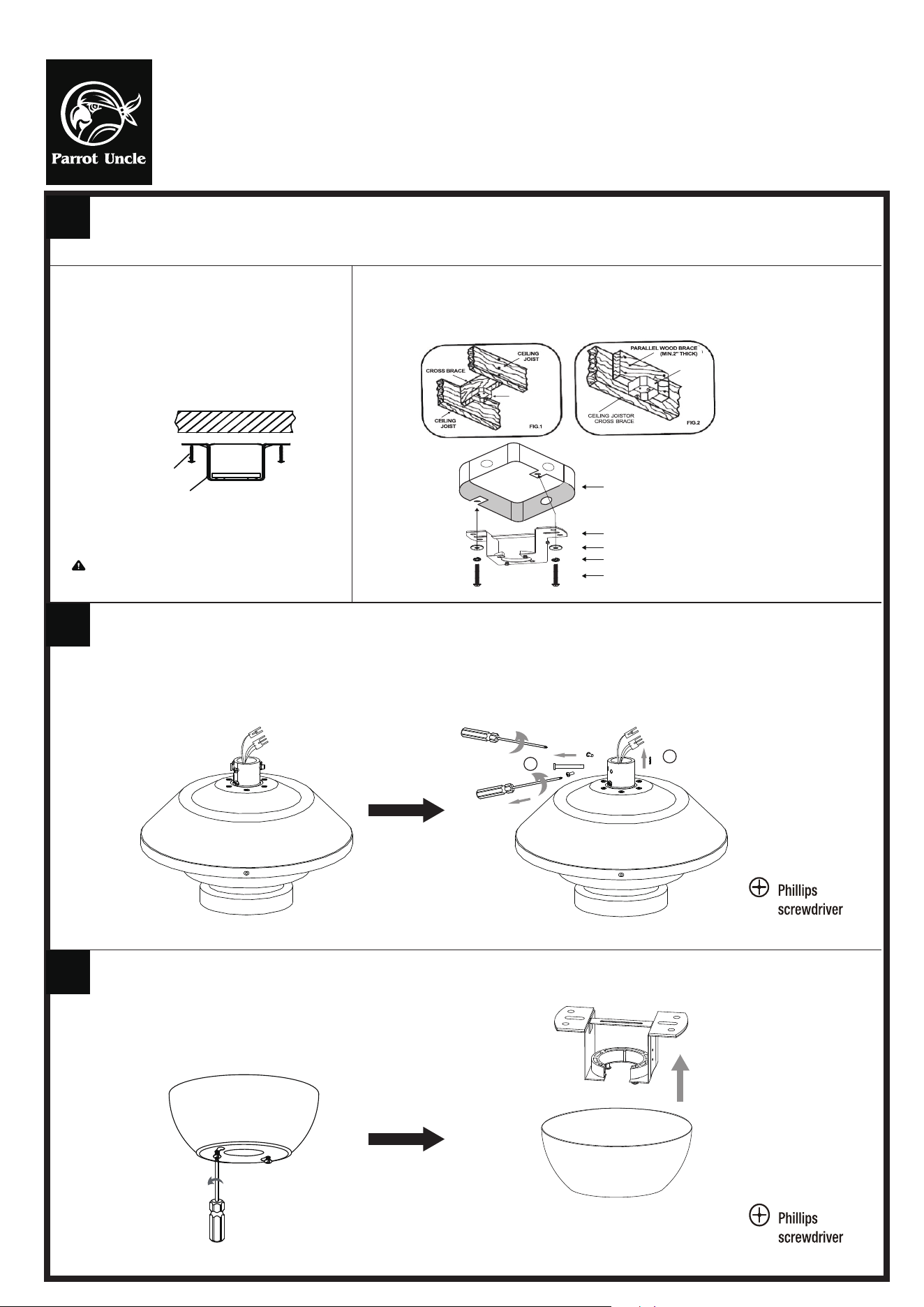
INSTALLING THE MOUNTING BRACKET:
The ceiling fan must be installed in a location so that the blades are 12” (300mm) spacing from the tip of the blade to the nearest objects or walls. When hanging
the Fan REMEMBER to turn off the power. Follow the instruction below to hang your fan properly:
1
2
3
1. For wood ceiing, secure the mounting bracket to the
ceiling is capable of carrying a load of at least 100lbs
(45kgs) with two long mounting screws and washers
provided. Be sure at least 0.12” (30mm) of the screw is
threaded into the support.
2 .For installing to junction box, secure the junction box directly to the building structure. Use appropriate
fasterners and building materials. The junction box and its support must be able to fully support the
moving weight of the fan (at least 100lbs). Use a UL listed metal junction box (Not Included). Do not use
a plastic junction box. Figure1 & 2 examples to mount the junction box (Not Included).
Wood ceiling
Wood screw 4 PCS
Mounting bracket
Note: Check whether it is securely installed.
Junction box (Not Included)
Mounting bracket
Washers
Spring washers
Mounting screws
Use a Phillips screwdriver to loosen the screw in the direction of the arrow shown in the figure, and place the screw for subsequent installation.
1
2
JUNCTION
BOX
JUNCTION
BOX
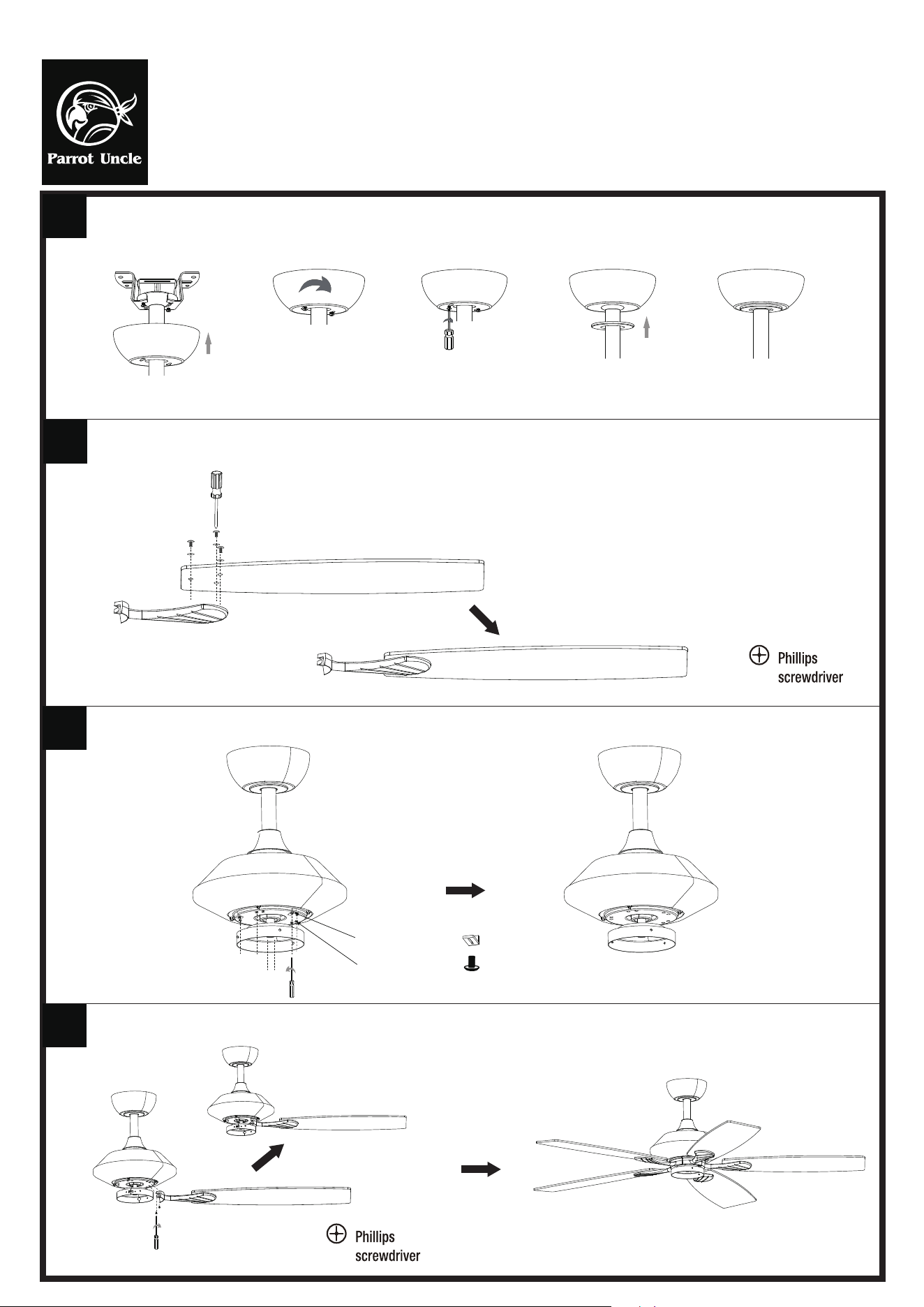
Loose 2 screws of the mounting bracket under the canopy, removed the
mounting bracket from the canopy.
Installation & Operating Instructions for the
Parrotuncle Owner's Installation, Manual
WARNING: SHUT POWER OFF AT FUSE OR CIRCUIT BERAKER
F6391110V
4
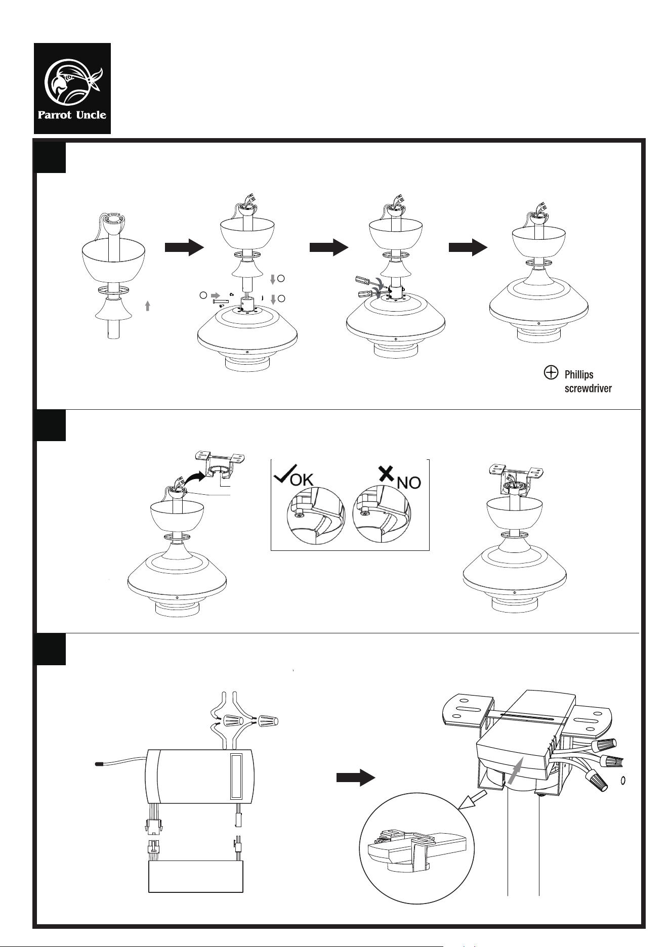
Install the suspension system components of the product as shown in the diagram.
5
6
Carefully lift the fan motor assembly onto the mounting bracket that was attached to the outlet box. Turn the entire assembly until the check tab (stopper of
bracket) drops into the notch of the downrod ball and seats firmly.
Tab
Notch
Connect the wires of the fan main unit with remote controller, connect the remote controller to the power supply using wire nuts.
WHITE
INPUT
RED/BLACK
OUTPUT
ANT
Power source 110~120 Vac 60Hz
Fan main unit
2
3
1
Installation & Operating Instructions for the
Parrotuncle Owner's Installation, Manual
WARNING: SHUT POWER OFF AT FUSE OR CIRCUIT BERAKER
F6391110V
7
Install the canopy to the screws of the mounting bracket, tighten the screws and cover the canopy
cover.
8
Attach the fan blade to the fan blade bracket using the blade screws and washers provided, tighten them firmly. Complete 5 blades assembly.
9
Remove 10 screws from the motor assembly and remove 3 reforcing pieces, place the screws for subsequent.
10
Attach the blade assembly to the fan motor assembly using removed screws and tighten firmly.
3 X Reforcing Pieces
10 X Screws
Finish
Installation & Operating Instructions for the
Parrotuncle Owner's Installation, Manual
WARNING: SHUT POWER OFF AT FUSE OR CIRCUIT BERAKER
F6391110V
11
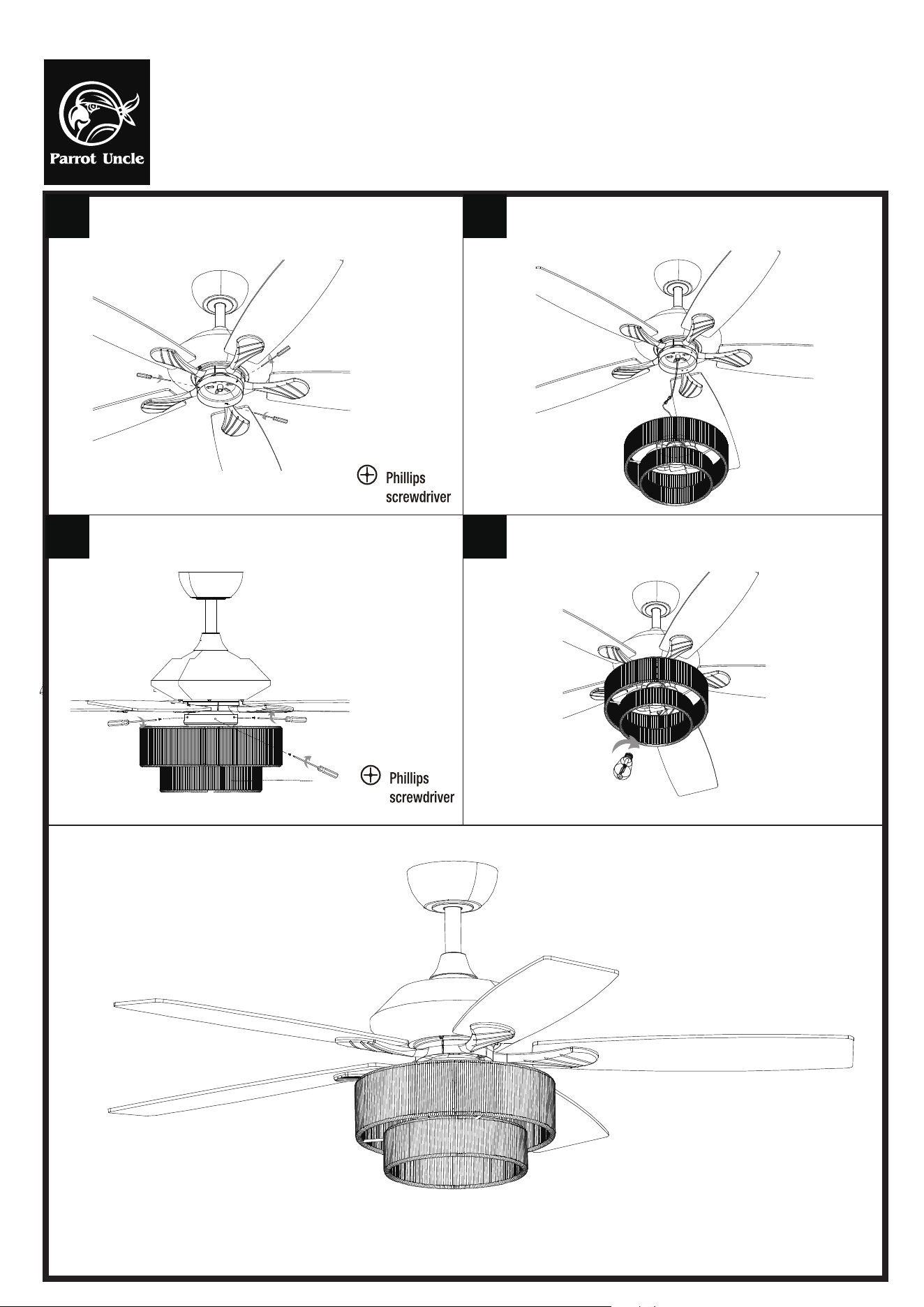
Remove 3 screws from motor assembly.
13
Attach the light kit to the fan motor assembly using
removed 3 screws and tighten firmly.
14
Install 2 E12 bulbs (not included) to the light fixture of the light kit.
12
Connect the wires of the fan motor assembly with light fixture of light kit.
INSTRUCTION OF INSTALLATION AND OPERATION
Remote controller
Installation & Operating Instructions for the
Parrotuncle Owner's Installation, Manual
WARNING: SHUT POWER OFF AT FUSE OR CIRCUIT BERAKER
F6391110V
CAUTION: Ceiling Angle Shall Not Exceed 30 Degrees,
For Mounting Controller.
Neutral wire N
To light live wire L
AC IN Black L
AC IN White N
Live Wire for Motor
Antenna
INPUT
OUTPUT
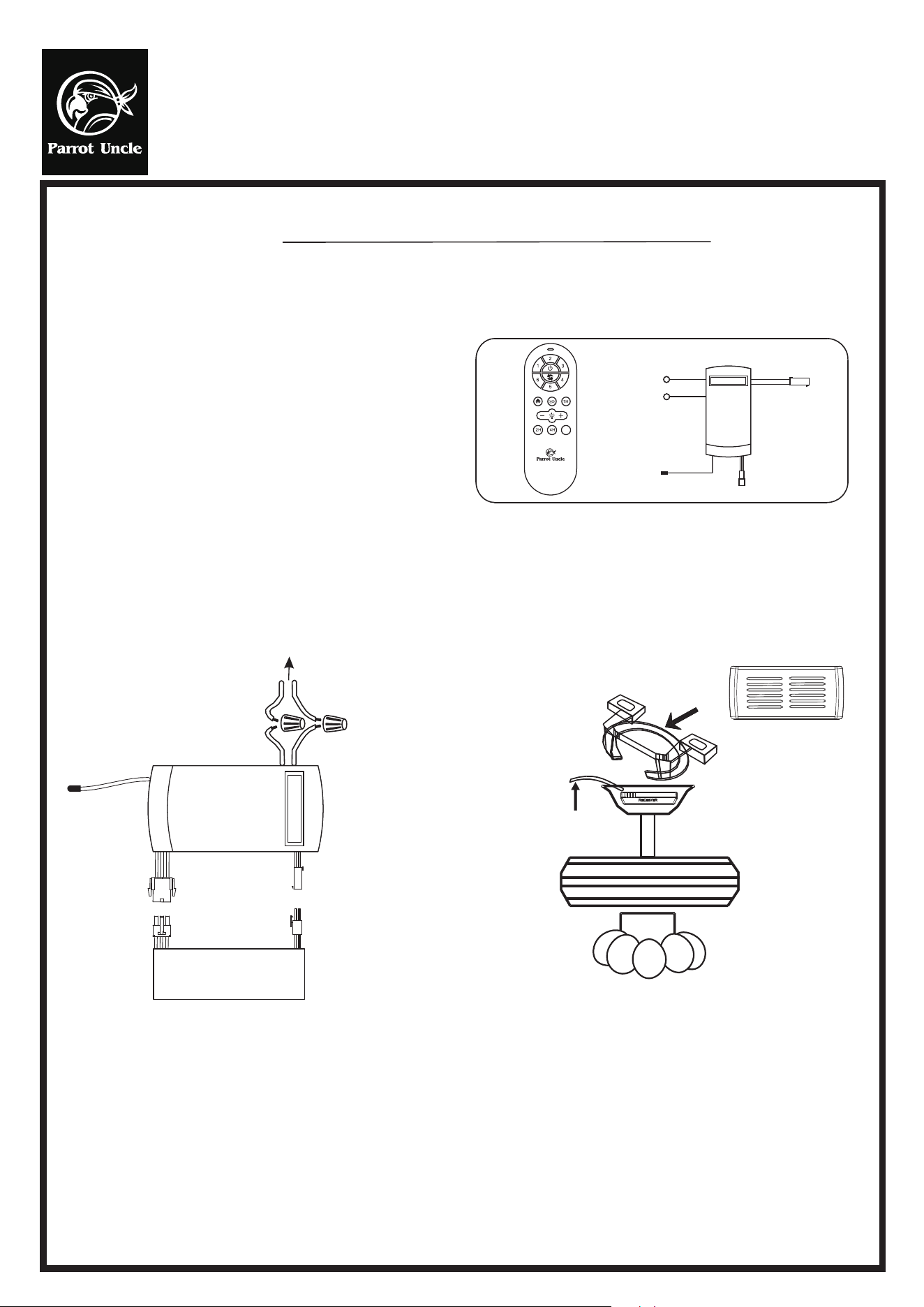
1. INSTALLING RECEIVER IN CEILING FAN
A. Safety precautions:
a. Remove power from the circuit.
b. Remove ceiling fan canopy from the mounting
bracket.
c. Disconnect existing wiring between ceiling fan
and Supply in electrical junction box.
d. Make connections as follows, using the wire nuts
supplied: (FIG.1)
WARNING: HIGH VOLTAGE! Disconnect power by
removing fuse or switching off circuit breaker.
Do not use with solid state fans.
Electrical wire must meet all local and national
electrical code requirements.
Supply for fan must be 110/120 volt, 60Hz. 3.5A
Maximumfan motor amps: 1.0, Maximum light watts:180
incandescent or ballast and LED.
Otherwise power can cause serious injury or death.
B. Installing receiver in fan: (FIG.2)
WHITE
INPUT
RED/BLACK
Use 2 wire connecting
nuts supplied with the fan
FROM POWER SOURCE AC 110~120 VOLT 60Hz 3.5AMPS.
Fan main unit
OUTPUT
ANT
FIG.1 FIG.2
RECEIVER
Antenna put at outside
of canopy box can get
more operation distance.
CANOPY
If other fans or supply wires are different color, have this unit installed by qualified licensed electrician.
a. Push all connected wires up into junction box.
b. Lay the brown antenna wire on top of the receiver, and put the receiver into the mounting bracket.
c. Reinstall the canopy on the mounting bracket.
d. Restore power.
e. Install 2 AAA 1.5 volt battery. (To prevent damage to transmitter, remove the battery if not used for a long time).
f. Store the transmitter away from excessive heat or humidity.
g.This remote control unit is equipped with roll code combinations. In order to prevent possible interference from or to other
remote units such as garage door openers,car alarm or security system. If you find that your fan and light kit go on and off
without using your remote control, simply change the code combination in your transmitter and receiver.
8H
Installation & Operating Instructions for the
Parrotuncle Owner's Installation, Manual
WARNING: SHUT POWER OFF AT FUSE OR CIRCUIT BERAKER
F6391110V
8H
1
3
4
2
6
7
8
5
9
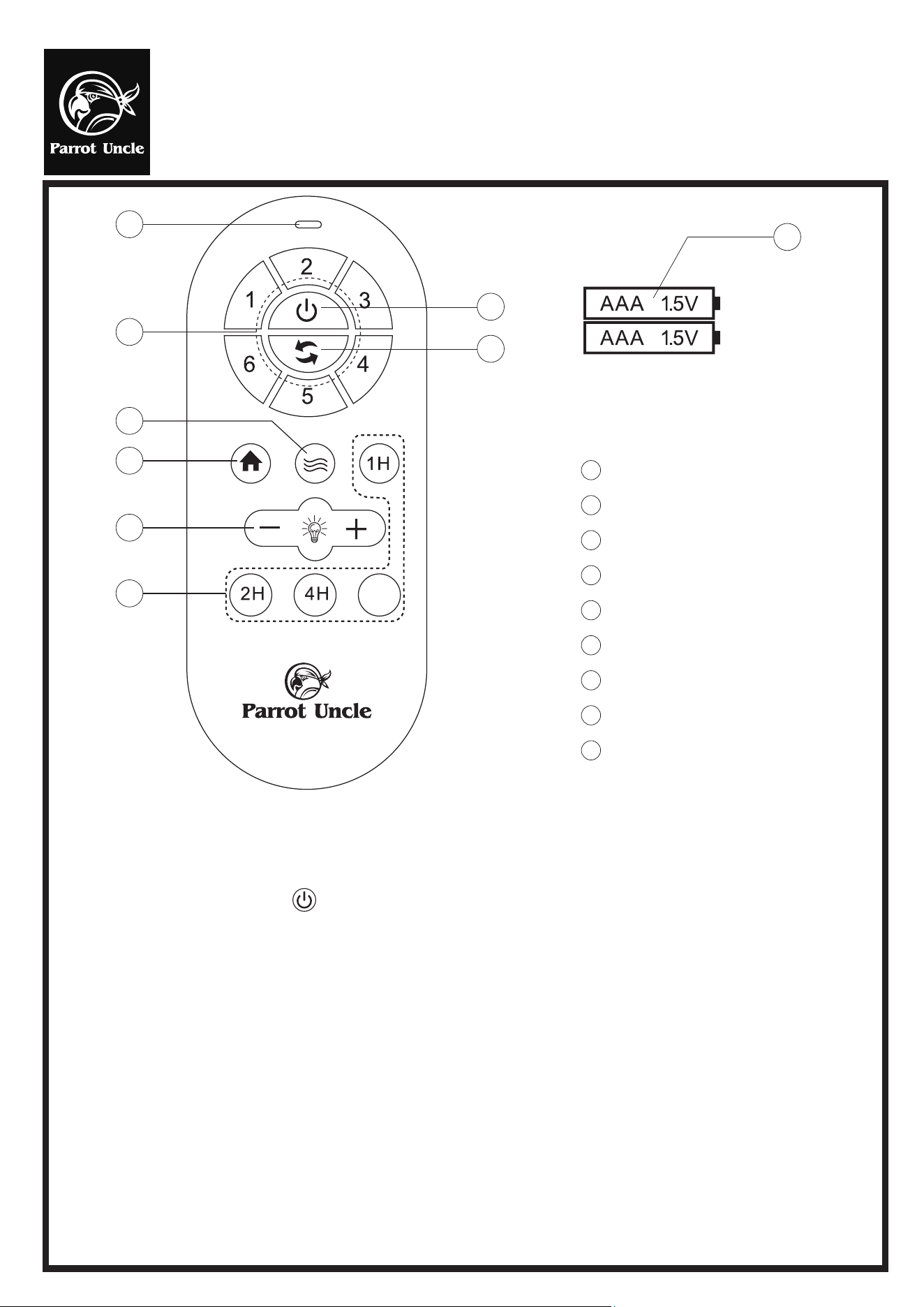
1 Switch Indicator
2 Speed Controller
3 Fan Power Switch
4 Fan Reverse
5 Natural Wind
6
Security
7 Light Switch
8 Timer
9 2 X1.5V AAA Battery
Actual use shall be subject to the real product
Learning method of remote control:
Power on the receiver, press the key at the emitter at once. The learning is succeed, when hear doule beep
ringing from the loud speaker.
NOTICES
1. When the emitter is unable to remotely control the receiver, please check whether the switch batteries are in good contact, whether
they are fixed properly and whether they run out of use.
2. When the emitter is unable to remotely control the receiver, please check whether there is other remote control products around the
space and check whether the keys are pressed down, because same nature of remote control product may cause interference with
each other resulting in poor receiving effect. Taking away such articles will normalize the remote control function. (the infrared
remote controller is not included).
3. Please use this product under applicable voltage. Too low voltage will lead to failure of the remote controller to work (Please refer to
the product label for the voltage range and related parameters).
4. Please take out the batteries if you will no use this product for a long time.
●
●
RF wireless digital transmission technology is adopted to realize the one-to-one control providing a rate of
coincident code less than 1/50000. Same code number is attached to the back of the emitter and the receiver.
It is required to return a pair of the same code number of emitter / receiver to the manufacturer for repair service in
case of any damage.
In a sufficient space, you can use the receiver at any angle, no worry about the direction.
Installation & Operating Instructions for the
Parrotuncle Owner's Installation, Manual
WARNING: SHUT POWER OFF AT FUSE OR CIRCUIT BERAKER
F6391110V
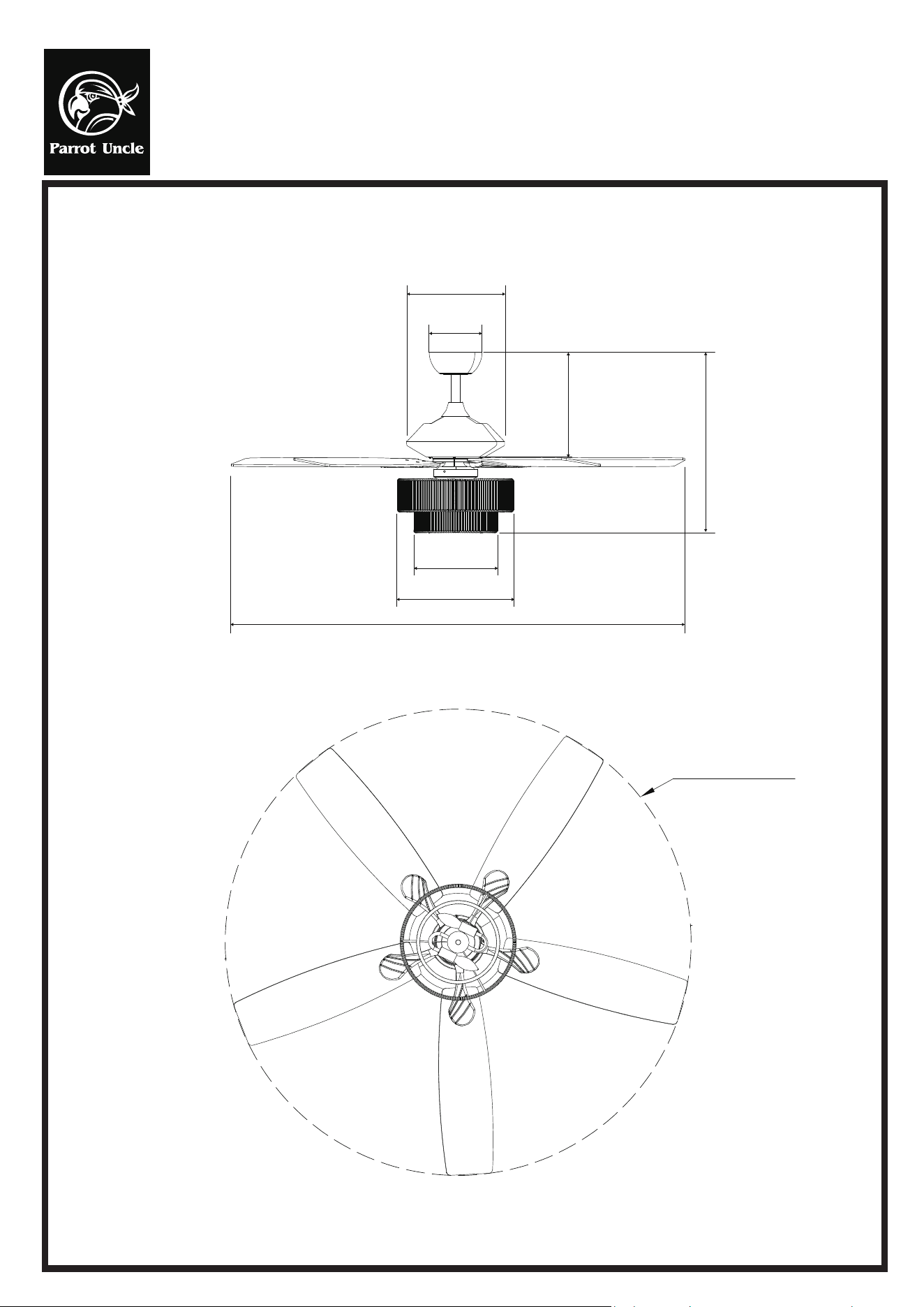
PRODUCT SIZE
52 in. (1320mm)
52 in. (1320mm)
Dia 5.9 in.
(Ø150mm)
Dia 11.9 in. (Ø278mm)
11.7 in. (297mm)
20.2 in. (512mm)
Dia 9.3 in.
(Ø237mm)
Dia 12.9 in. (Ø330mm)
Installation & Operating Instructions for the
Parrotuncle Owner's Installation, Manual
WARNING: SHUT POWER OFF AT FUSE OR CIRCUIT BERAKER
F6391110V
TROUBLESHOOTING GUIDE
Table of Contents
1. Fan / Remote is not working
2. Fan is noisy
3. Fan Wobbles
4. Light is not working
Please refer to the instruction sheet for detailed directions and descriptions of
installation steps and requirements
1. FAN / REMOTE IS NOT WORKING
Ensure the remote is within the 20 feet range of the receiver
To reset the remote control: 1) Turn off power to fan using the wall switch or circuit breaker. 2) Remove ba�eries from remote.
3) Wait 10 seconds. 4) Replace ba�eries and turn power on
Check ba�eries to insure they are good and oriented correctly
Check to make sure the frequency switches (DIP Switches) from the remote to the receiver are set to the same frequency
Check the main and branch circuit fuses or breakers
If using a Variable Speed Wall Switch, ensure it is specifically designed for use with a ceiling fan.
Check the line wire connec�ons to the fan and the switch wire connec�ons in the switch housing per the instruc�ons
If fan s�ll does not work, please contact Customer Service [email protected]
Make sure all motor housing screws are �ghtened
Make sure the screws that a�ach fan blade to motor are �ght
Make sure the wire nut connectors are not ra�ling against each other or the interior wall of the switch housing
Allow 24-hour break in period. Most noises associated with the new fan may disappear during this �me
If using a ceiling light kit, make sure the glassware is secured �ghtly
Make sure there is a short distance/gap from the ceiling to the top of the canopy. The canopy should not touch the ceiling!
Make sure your ceiling box is secure and that the rubber isolator pads are used between the moun�ng bracket and outlet box
2. THE FAN IS NOISY
Verify all blades and blade bracket screws are secure (most fan wobble problems are caused by loose parts). Once fan is properly
installed, run the ceiling fan for 10 minutes to let the fan self-adjust.
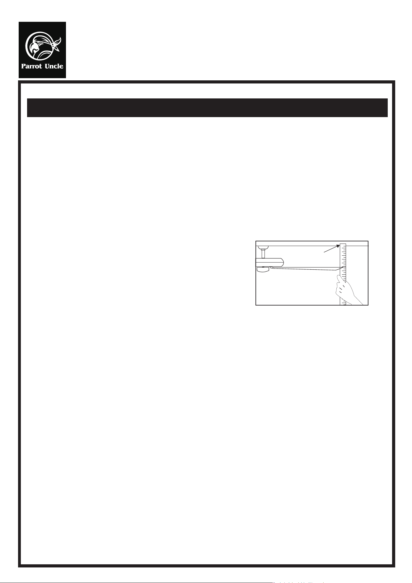
If wobble occurs a�er running the fan for 10 minutes, verify blade level using the following process:
a) select a point on the ceiling above the �p of one of the blades. Then select the fan blade and measure from the center
of the selected blade to point on the ceiling. Rotate the fan un�l the next blade is posi�oned and repeat the
measurement using the same point from the ceiling for every blade. Measurements should be within 1/8 inch.
3. THE FAN WOBBLES
b) If all devia�on are less than 1/8 inch and the fan con�nues to wobble, please contact Customer Service Support@parr
otuncle.com to order a complimentary Blade Balancing Kit
- If all devia�ons are less than 1/8 inch and the fan con�nues to wobble, please contact Customer Service Support@parrotuncle
.com to order a complimentary Blade Balancing Kit
4. LIGHT IS NOT WORKING
Check Bulb to make sure it is installed correctly
Remove non-working bulb and replace with a bulb that is known to be a good working bulb
To reset the remote control: 1) Turn off power to fan using the wall switch or circuit breaker. 2) Remove ba�eries from
remote. 3) Wait 10 seconds. 4) Replace ba�eries and turn power on
Installation & Operating Instructions for the
Parrotuncle Owner's Installation, Manual
WARNING: SHUT POWER OFF AT FUSE OR CIRCUIT BERAKER
F6391110V
The fan blades have been adjusted in the factory to minimize any wobble
AFTER INSTALLATION
WOBBLE
NOTE: CEILING FANS TEND TO MOVE DURING OPERATION DUE TO THE FACT THAT THEY ARE MOUNTED ON A RUBBER
CROMMET. IF THE FAN WAS MOUNTED RIGIDLY TO THE CEILING, IT WOULD CAUSE EXCESS VIBRATION. MOVEMENT OF
A FEW CENTIMENTERS IS QUITE ACCEPTABLE AND DOES NOT SUGGEST ANY PROBLEM
TO REDUCE THE FAN WOBBLE, PLEASE CHECK THAT ALL SCREWS WHICH SECURED THE MOUNTING BRACKET AND
DOWNROD ARE SECURE.
For your convenience, a Balancing Kit is included, please follow this procedure when balancing the fan:
BALANCING A WOBBLING CEILING FAN
1. Check that all blade and blade arm screws are secure.
2. Most fan wobbling problems are caused when blade levels are unequal.
Check this level by selec�ng a point on the ceiling above the �p of one of
the blades. Measure this distance. Rotate the fan un�l the next blade is
posi�oned for measurement. Repeat for each blade. The distance devia�on
should be equal within 1/8"(0.32cm).
3. If the blade wobble is s�ll no�ceable, use the enclosed Blade Balancing Kit.
4. If the blade wobble is s�ll no�ceable, interchanging two adjacent (side by side) blades can redistribute the weight and
possibly result in smoother opera�on.
WARNING: TO REDUCE THE RISK OF PERSONAL INJURY, DO NOT BEND THE BLADE ARM WHILE INSTALLING, BALANCING
THE BLADES, OR CLEANING THE FAN. DO NOT INSERT FOREIGN OBJECTS BETWEEN ROTATING FAN BLADES.
NOISE
When it is quiet (especially at night) you may hear occasional small noises. This is normal. Please allowa 24-hour “breaking-in”
period, most noises associated with a new fan disappear during the �me.
CARE AND CLEANING
1. Periodic cleaning of your ceiling fan is the only maintenance required. Use a so� brush or lint free cloth to avoid scratching
the paint finish. Please make sure to turn off electricity power before you clean your fan
2. Do not use water when cleaning your ceiling fan. It could damage the motor or the blades and create the possibility of an
electrical shock.
3. Motor has permanently lubricated ball bearing. No need to oil
NOTE:
MAKE SURE THE POWER IS OFF AT THE ELECTRICAL PANEL BOX BEFORE YOU ATTEMPT
ANY CLEANING OR REPAIRS.
Tauching
ceiling