www.parrotuncle.com
English
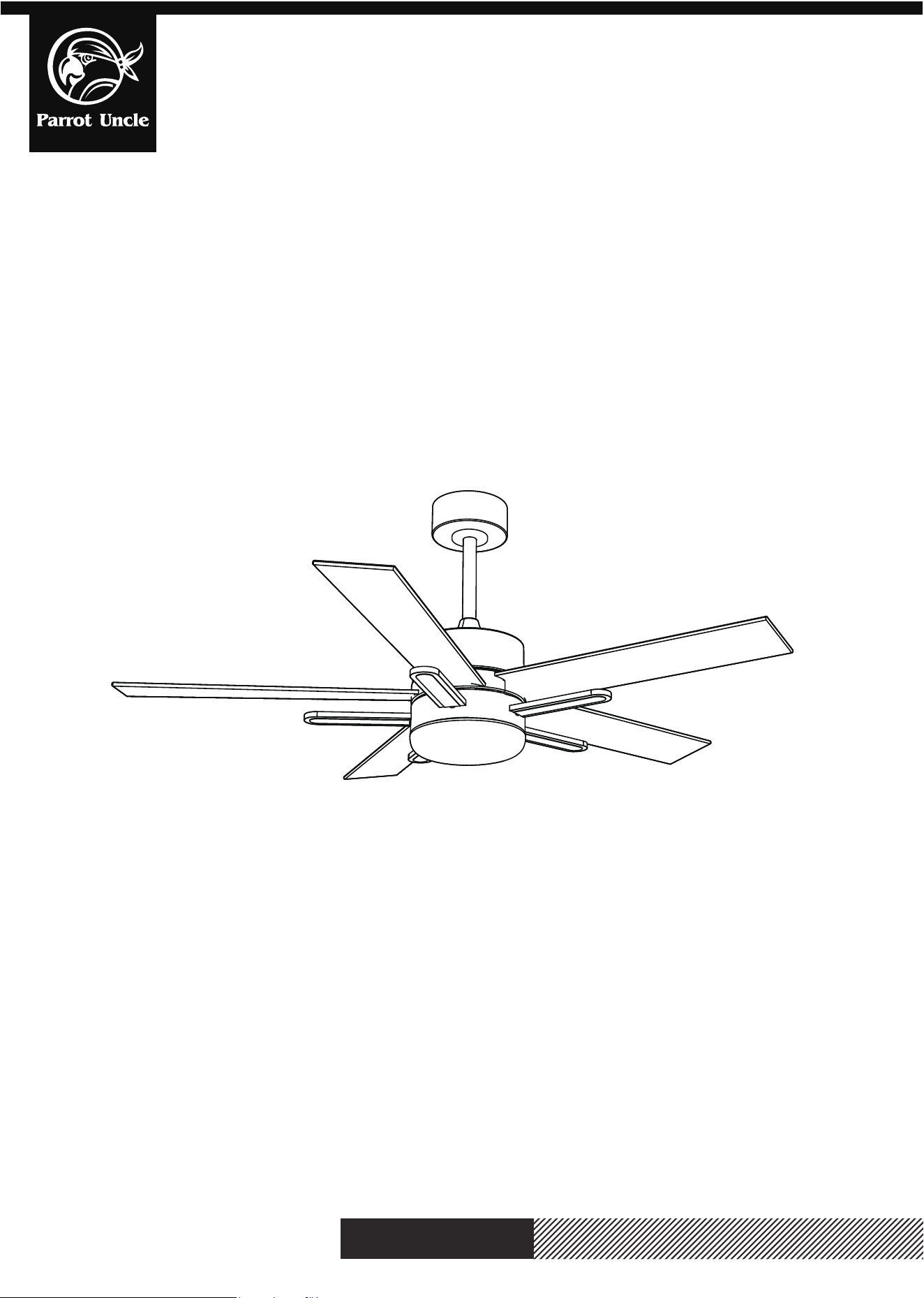
F6013
Sicherheit information
1. To reduce the risk of an electrical blow, electricity on the
2. All wiring must correspond to the NASI/NFPA 70-1999
approved electrician.
3.
assembled safely and 35 pounds (15.9 kilos) must be able
to transport reliably. Use only output boxes listed with
labeling
"Accepted for fans with a weight of £ 35 (15.9 kilos) or less."
4. The fan must be installed with a minimum distance of 2.1 m
(7 feet) from the posterior edge of the blades to the floor.
5. Do not operate the reverse switch if the fan blades are
moving. You have to turn off the fan and stop the blades
6. Do not place objects on the road to blades.
7. To avoid lesions or damage to the fan and other objects, be
careful if you work on the fan or clean it.
8.
rates that are not delivered with the fan must be listed and
marked with the valve model that will be installed for use.
The switches must be general use switches UL. Take into
9.
staircase must be turned up and carefully push to the plug
box. The cables must be distributed in such a way that the
ground connected driver and the device head are next to
the socket.
necessary, followed.
WARNING: To reduce the risk of injury, blade brackets
cannot be folded during
Do not put any object on the path of blades.
WARNING:
Remove rubber motor
at the
of the fan before the blades or try
the motor.
WARNING: To avoid the risk of a fire or an
electrical blow, this fan should not be used with a
semiconductor speed controller.
WARNING: To avoid a possible electric shock,
turn off the current in the main security box
before wiring. If you feel that you do not have
enough knowledge or experience in electrical
wiring, communicate with a license electrician.
WARNING: Electrical diagrams only serve as a
be on the list and marked with this fan for use.
WARNING: To reduce the risk of fires, electrical
discharges or injuries, assemble the device in a
with a weight of £ 35) or less. It is marked and use
the screws supplied with the plug.
TECHNICAL INFORMATION
SKU
Nominal voltage
14W
Main light 24W 3000/4000/5000K,dimmable
Side light 7W 3000/4000/5000K
Nominal output (motor) light
Installation & Operating Instructions for the
Parrot uncle Owner's Installation ,Manual
WARNING: SHUT POWER OFF AT FUSE OR CIRCUIT BREAKER
F6013
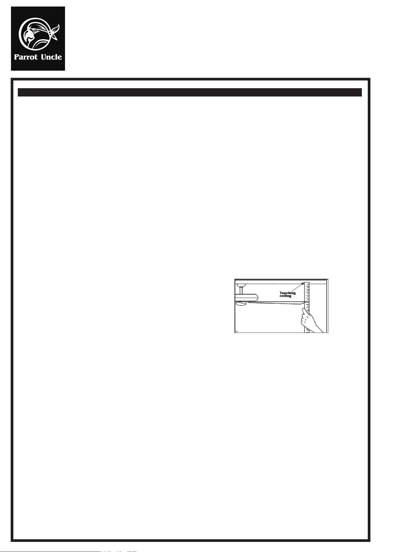
Make sure that there is a space of at least 30 cm between the
fan’s blades and any wall or other obstacle with which they
could collide.It is important to note that the greater the
distance,the more efficient the airflow would be.
0,3m
1
110-120V ACF6013
Installation & Operating Instructions for the
Parrot uncle Owner's Installation ,Manual
WARNING: SHUT POWER OFF AT FUSE OR CIRCUIT BREAKER
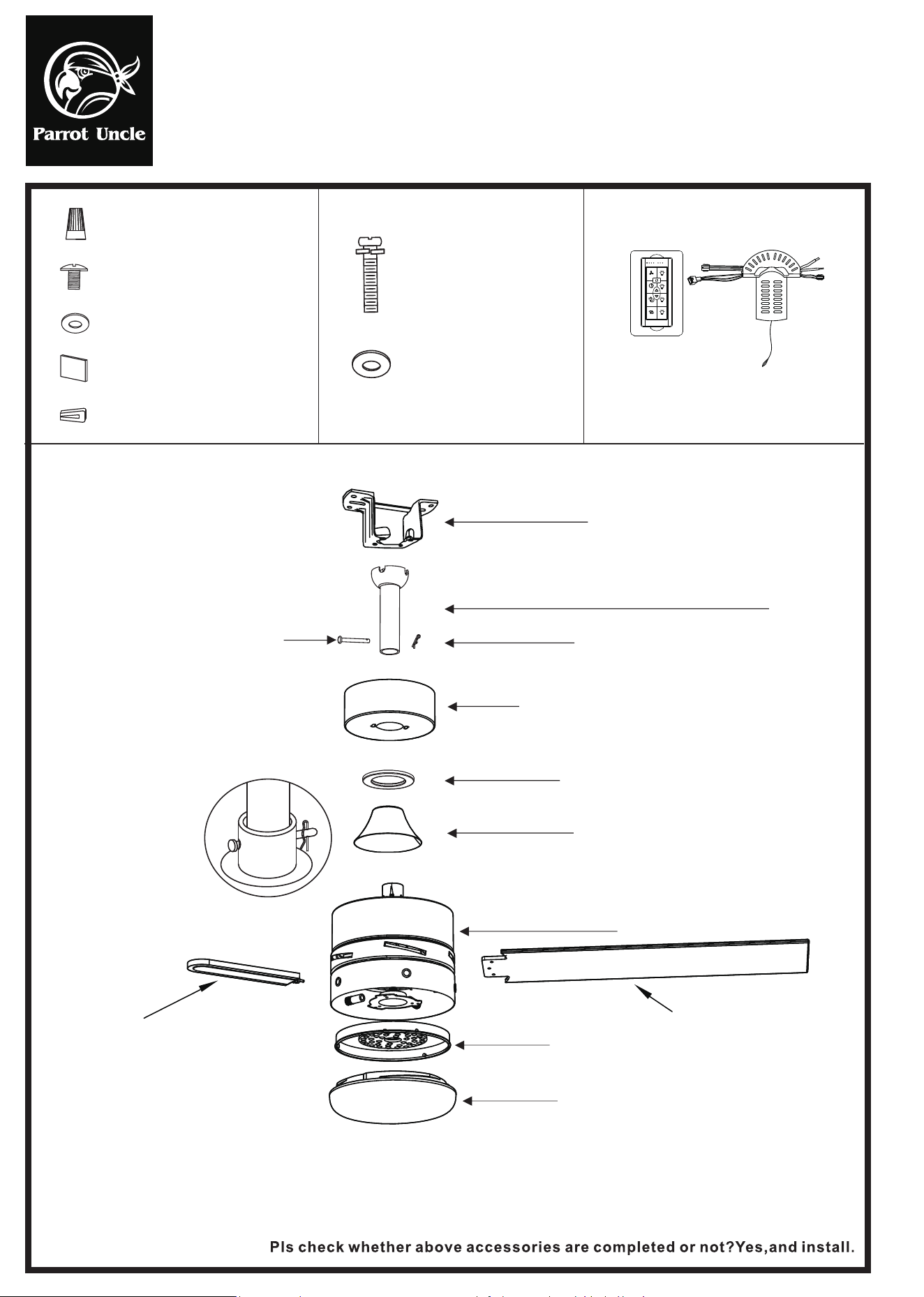
Remote control (1 PC)
F6013
Mounting screw(2PCS)
Washer(2PCS)
Plastic wire nut (3PCS)
Blade screw (1PCS)
Washer (16PCS)
5g
Balancing sticker (2PCS)
Balancing clip (1PC)
ON/OFF
ON/OFF
2H
4” Ball/downrod assembly and 10” downrod
Bolt “R” Lock Pin
Canopy
Canopy cover
Coupling cover
Blade 5PCS
Side light 5PCS
Fan-motor assembly
Light cover
Main light
Moun�ng bracket
1
Installation & Operating Instructions for the
Parrot uncle Owner's Installation ,Manual
WARNING: SHUT POWER OFF AT FUSE OR CIRCUIT BREAKER
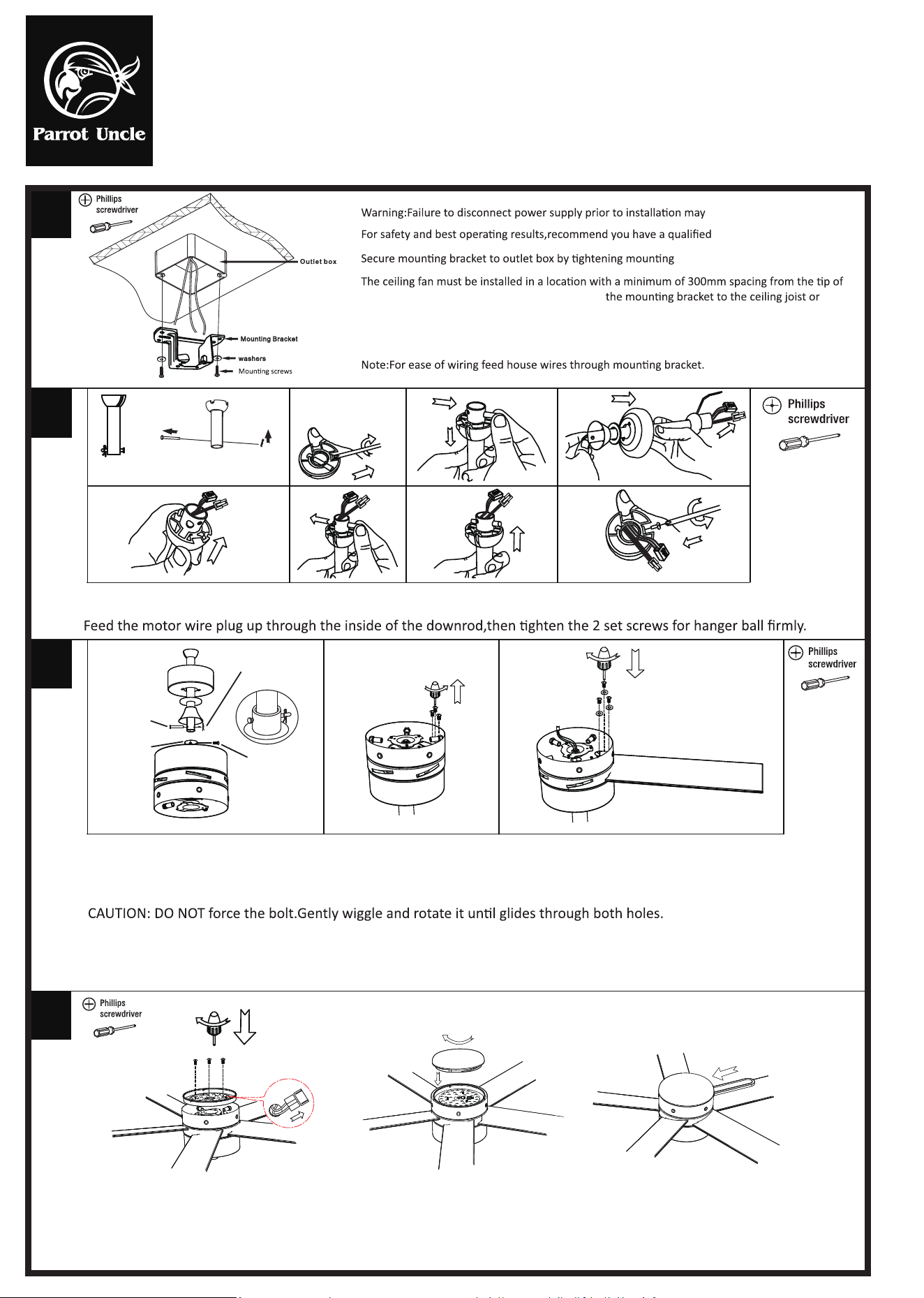
result in serious injury.
electrician install this fan.
screws & washers.
the blade to the nearest objects or walls.Secure
structure that is capable of carrying a load of at least 15.9kgs,with two long screws provided.
Ensure at least 30mm of the screws is threaded into the support.
X2
Remove the bolt,”R” lock pin and 2 set screws from the downrod and then take down the hanger ball.
Insert the downrod into the coupling.
Gently push the bolt through the holes alighed with the base of the coupling and downrod.
Insert “R” lock pin into bolt and secure downrod with 2 set screws.
3
4
2
F6013
x2
X15
Remove 15 pre-installed screws from motor.
coupling
2 set screws
“R” lock pin
Bolt
X15
X5
X15
Install 5 blades to motor by using 15 screws and washers provided.Tighten screws securely.
X3
Insert the motor plug into the LED board slot,and then install the main light to motor with 3 pre-installed screws.
Aligh groove in light cover with ridge in main light.Twist light cover clockwise un�l it is secure.
Insert 5 side lights into holes of main light.Ensure it is secure.
X5
Installation & Operating Instructions for the
Parrot uncle Owner's Installation ,Manual
WARNING: SHUT POWER OFF AT FUSE OR CIRCUIT BREAKER
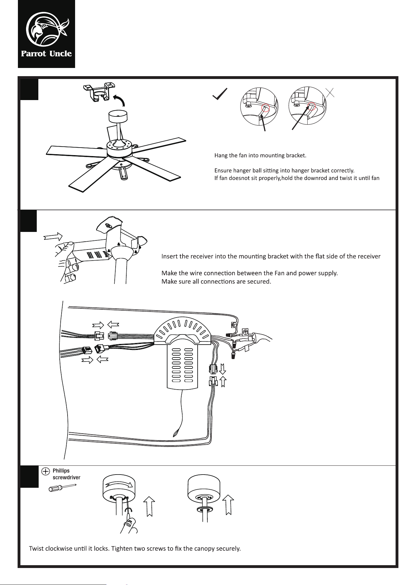
Aligh ball groove on hanger ball with ridge on hanger bracket.
has been secured into hanger bracket.
WARNING: Failure to aligh ball groove with ridge may result in serious injury.
ball groove
Ridge
5
OK
NO
F6013
facing the ceiling.
WARNING: To avoid possible electrical shock, be sure electricity is turned off
at the main fuse box before wiring.
6
6
Slide the canopy up to ceiling and align the keyhole slots on the canopy with the 2 preassembled screws on the hanger bracket.
Clip the canopy cover in to secure it onto the canopy.
7
B
A
FROM POWER SOURCE
AC 110- 120 VOLT 60Hz
3.5AMPS.
supplied with the
Use plastic wire nuts
fan
Ground wire
L
N
black
White
MOTOR
INSERT
INSERT
Installation & Operating Instructions for the
Parrot uncle Owner's Installation ,Manual
WARNING: SHUT POWER OFF AT FUSE OR CIRCUIT BREAKER
Remote controller
GENERAL INFORMATION
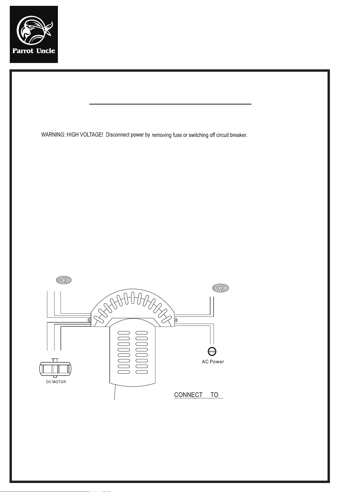
1.INSTALLING RECEIVER IN CEILING FAN
A. Safety precautions:
Do not use with solid state fans.
electrical code requirements.
C. Installing receiver in fan:
a. Remove power from the circuit.
bracket.
Supply in electrical junction box.
supplied:
B. Electrical rating: 110/120V 60Hz
Electrical wire must meet all local and national
Otherwise power can cause serious injury or death.
b. Remove ceiling fan canopy from the mounting
c. Disconnect existing wiring between ceiling fan and
d. Make connections as follows, using the wire nuts
MAX. Motor watts: 30 W
MAX. Light watts: 24W
F6013
MAX.Side Light watts:15W
Main
(FIG.1)
Side light
AC IN N
AC IN L
ANT
for Light 1
for Ligh
t 2
fo
r Light 3
for Mo
tot 1
for Moto 2
fo
r Moto 3
(FIG.1)
Black receiver wire(AC IN L) ....Red or Black supply wire
White receiver wire(AC IN N) ....White supply wire
Red receiver wire(TO MOTOR 1)....Red fan wire
Gray receiver wire(TO MOTOR 2) ....Gray fan wire
Ping receiver wire(TO MOTOR 3)....Ping fan wire
Yellow receiver wire(FOR LIGHT 1) ....Yellow light wire
Red receiver wire(FOR LIGHT 2) ....Red light wire
White receiver wire(FOR LIGHT 3)....Whitelight wire
Blue receiver wire(FOR NIGHT LIGHT L) ....Blue light wire
White receiver wire(FOR NIGHT LIGHT N) ....W
hite light wire
Main light
for Side Light L for Side Light N
Installation & Operating Instructions for the
Parrot uncle Owner's Installation ,Manual
WARNING: SHUT POWER OFF AT FUSE OR CIRCUIT BREAKER
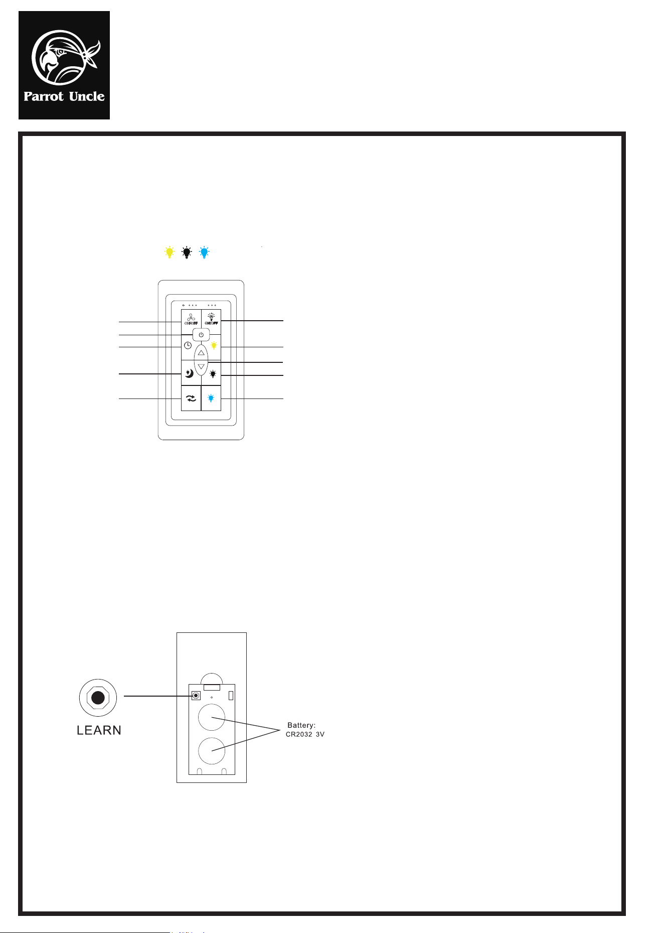
2. OPE RATI NG TRAN SMITTER :
(To prev ent da mag e to tran smitter , remov e the batter y if not us ed for a long time).
B. Stor e the tran smitter away from exces sive he at or humidity.
C. Operat ing the bu ttons on the pa nel of the transmitter .
The Learn Key must be press ed with in 5 seconds ,
after press ing the Power button.
If not, please pre
ss the Power button to rest art.
Keep pressing the button LEARN key in exc ess of 3 se cond it beco mes a LEARN st atus.
The receive r can remember the last codes st atus .
The ceiling fan light flash two times.
E. Setting the codes on the receive r:
D
F6013
Fan ON/OFF
Side Light Mode
All OFF
FAN Timing
2H
Foward/Reverset
Light ON/OFF
Natural light
White Light
Warm Light
FAN Speed1-6
LEAR N
A. Install 2*2032 3 volt battery.
Long press the" " button,brighten/dim the
light continuously.
(FIG.2)
(FIG.2)
(FIG.3)
(FIG.3)
.
Installation & Operating Instructions for the
Parrot uncle Owner's Installation ,Manual
WARNING: SHUT POWER OFF AT FUSE OR CIRCUIT BREAKER
F6013
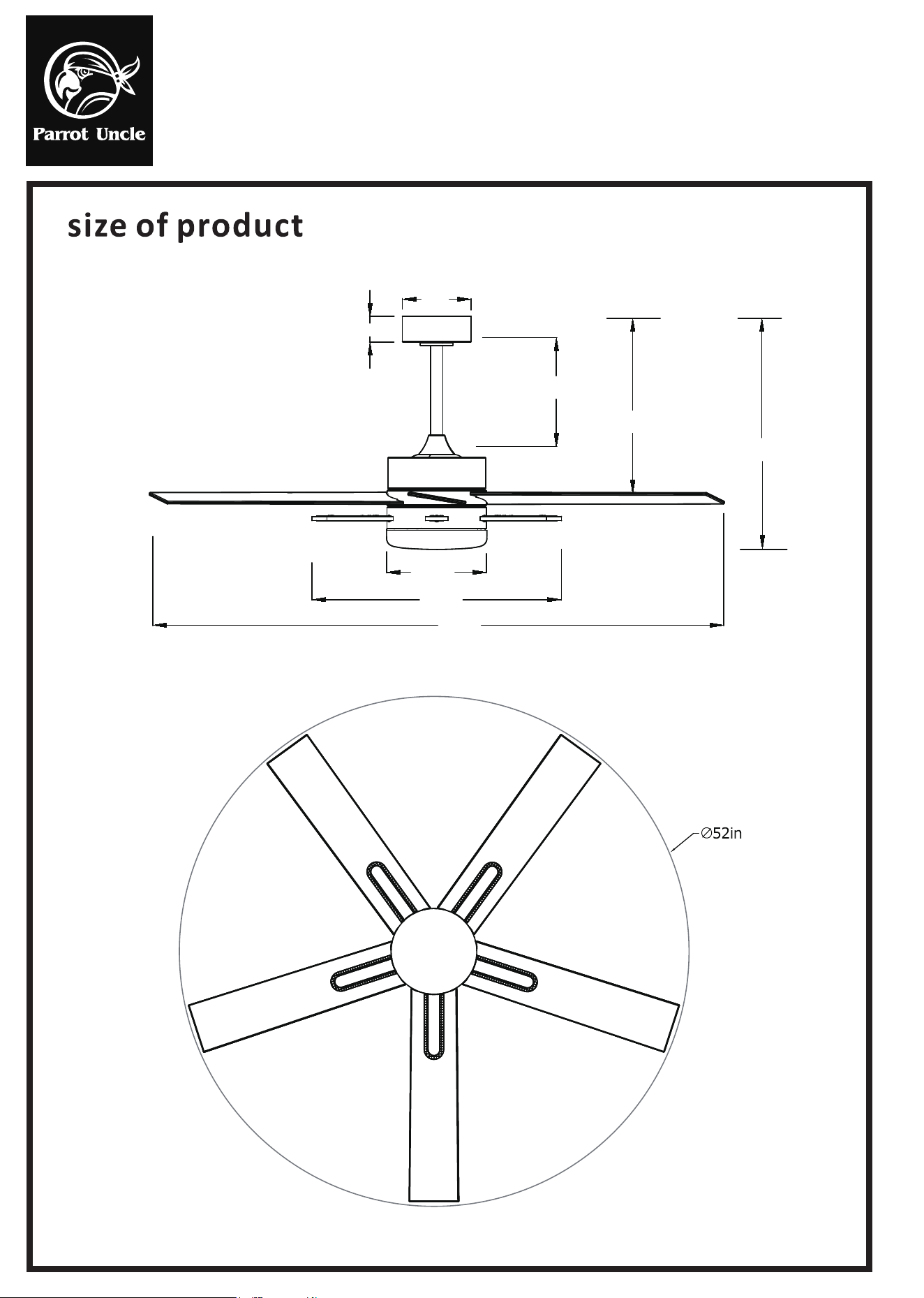
15.5 or 21.5in
6in
2.5in
4 or 10in
52in
11 or 17in
8.5in
22in
AFTER INSTALLATION
The fan blades have been adjusted in the factory to minimize any wobble
NOTE:CEILING FANS TEND TO MOVE DURING OPERATION DUE TO THE FACT THAT THEY
ARE MOUNTED ON A RUBBER CROMMET. IF THE FAN WAS MOUNTED RIGIDLY TO THE
CEILING, IT WOULD CAUSE EXCESS VIBRATION. MOVEMENT OF A FEW CENTIMENTERS
IS QUITE ACCEPTABLE AND DOES NOT SUGGEST ANY PROBLEM
WOBBLE”
TO REDUCE THE FAN WOBBLE: PLEASE CHECK THAT ALL SCREWS WHICH SECURED THE MOUNTING
BRACKET AND DOWNROD ARE SECURE.
BALANCING A WOBBLING CEILING FAN:
1.Check that all blade and blade arm screws are secure.
2.Mos
t fan wobbling problems are caused when blade levels are unequal. Check this level by
selecting a point on the ceiling above the tip of one of the
blades. Measure this distance.Rotate the fan until the next blade is positioned for
measurement. Repeat for each blade. The distance deviation should be equal within
1/8"(0.32cm).
3.If the blade wobble is still noticeable, interchanging two
adjacent (side by side) blades can redistribute the weight
and possibly result in smoother operation. WARNING: TO REDUCE THE RISK OF PERSONAL
INJURY, DO NOT BEND THE BLADE ARM WHILE INSTALLING, BALANCING THE BLADES, OR
CLEANING THE FAN. DO NOT INSERT FOREIGN OBJECTS BETWEEN ROTATING FAN BLADES.
NOISE
When it is quiet(especially at night) you may hear occasional small noises. This is normal. Please allow a 24-
hour “breaking-in” period, most noises associated with a new fan disappear during the time.
CARE AND CLEANING
1.Periodic cleaning of your ceiling fan is the only maintenance required. Use a soft brush or lint free cloth to
avoid scratching the paint finish. Please make sure to turn off electricity power before you clean your fan
2.Do not use water when cleaning your ceiling fan. It could damage the motor or the blades
and create the possibility of an electrical shock.
3.Motor has permanently lubricated ball bearing. No need to oil
NOTE: MAKE SURE THE POWER IS OFF AT THE ELECTRICAL PANEL BOX BEFORE YOU
ATTEMPT ANY CLEANING OR REPAIRS.
Installation & Operating Instructions for the
Parrot uncle Owner's Installation ,Manual
WARNING: SHUT POWER OFF AT FUSE OR CIRCUIT BREAKER
F6013
Pot Uncle